EP2177832A2 - Method and apparatus for introducing diluent flow into a combustor - Google Patents
Method and apparatus for introducing diluent flow into a combustor Download PDFInfo
- Publication number
- EP2177832A2 EP2177832A2 EP09172916A EP09172916A EP2177832A2 EP 2177832 A2 EP2177832 A2 EP 2177832A2 EP 09172916 A EP09172916 A EP 09172916A EP 09172916 A EP09172916 A EP 09172916A EP 2177832 A2 EP2177832 A2 EP 2177832A2
- Authority
- EP
- European Patent Office
- Prior art keywords
- piston ring
- fuel nozzle
- combustor
- diluent
- shroud
- Prior art date
- Legal status (The legal status is an assumption and is not a legal conclusion. Google has not performed a legal analysis and makes no representation as to the accuracy of the status listed.)
- Withdrawn
Links
Images


Classifications
-
- F—MECHANICAL ENGINEERING; LIGHTING; HEATING; WEAPONS; BLASTING
- F23—COMBUSTION APPARATUS; COMBUSTION PROCESSES
- F23R—GENERATING COMBUSTION PRODUCTS OF HIGH PRESSURE OR HIGH VELOCITY, e.g. GAS-TURBINE COMBUSTION CHAMBERS
- F23R3/00—Continuous combustion chambers using liquid or gaseous fuel
- F23R3/02—Continuous combustion chambers using liquid or gaseous fuel characterised by the air-flow or gas-flow configuration
- F23R3/04—Air inlet arrangements
-
- F—MECHANICAL ENGINEERING; LIGHTING; HEATING; WEAPONS; BLASTING
- F23—COMBUSTION APPARATUS; COMBUSTION PROCESSES
- F23L—SUPPLYING AIR OR NON-COMBUSTIBLE LIQUIDS OR GASES TO COMBUSTION APPARATUS IN GENERAL ; VALVES OR DAMPERS SPECIALLY ADAPTED FOR CONTROLLING AIR SUPPLY OR DRAUGHT IN COMBUSTION APPARATUS; INDUCING DRAUGHT IN COMBUSTION APPARATUS; TOPS FOR CHIMNEYS OR VENTILATING SHAFTS; TERMINALS FOR FLUES
- F23L7/00—Supplying non-combustible liquids or gases, other than air, to the fire, e.g. oxygen, steam
- F23L7/002—Supplying water
- F23L7/005—Evaporated water; Steam
-
- F—MECHANICAL ENGINEERING; LIGHTING; HEATING; WEAPONS; BLASTING
- F23—COMBUSTION APPARATUS; COMBUSTION PROCESSES
- F23R—GENERATING COMBUSTION PRODUCTS OF HIGH PRESSURE OR HIGH VELOCITY, e.g. GAS-TURBINE COMBUSTION CHAMBERS
- F23R3/00—Continuous combustion chambers using liquid or gaseous fuel
- F23R3/28—Continuous combustion chambers using liquid or gaseous fuel characterised by the fuel supply
- F23R3/283—Attaching or cooling of fuel injecting means including supports for fuel injectors, stems, or lances
-
- F—MECHANICAL ENGINEERING; LIGHTING; HEATING; WEAPONS; BLASTING
- F23—COMBUSTION APPARATUS; COMBUSTION PROCESSES
- F23R—GENERATING COMBUSTION PRODUCTS OF HIGH PRESSURE OR HIGH VELOCITY, e.g. GAS-TURBINE COMBUSTION CHAMBERS
- F23R3/00—Continuous combustion chambers using liquid or gaseous fuel
- F23R3/42—Continuous combustion chambers using liquid or gaseous fuel characterised by the arrangement or form of the flame tubes or combustion chambers
- F23R3/44—Combustion chambers comprising a single tubular flame tube within a tubular casing
-
- F—MECHANICAL ENGINEERING; LIGHTING; HEATING; WEAPONS; BLASTING
- F23—COMBUSTION APPARATUS; COMBUSTION PROCESSES
- F23R—GENERATING COMBUSTION PRODUCTS OF HIGH PRESSURE OR HIGH VELOCITY, e.g. GAS-TURBINE COMBUSTION CHAMBERS
- F23R3/00—Continuous combustion chambers using liquid or gaseous fuel
- F23R3/42—Continuous combustion chambers using liquid or gaseous fuel characterised by the arrangement or form of the flame tubes or combustion chambers
- F23R3/60—Support structures; Attaching or mounting means
-
- F—MECHANICAL ENGINEERING; LIGHTING; HEATING; WEAPONS; BLASTING
- F23—COMBUSTION APPARATUS; COMBUSTION PROCESSES
- F23L—SUPPLYING AIR OR NON-COMBUSTIBLE LIQUIDS OR GASES TO COMBUSTION APPARATUS IN GENERAL ; VALVES OR DAMPERS SPECIALLY ADAPTED FOR CONTROLLING AIR SUPPLY OR DRAUGHT IN COMBUSTION APPARATUS; INDUCING DRAUGHT IN COMBUSTION APPARATUS; TOPS FOR CHIMNEYS OR VENTILATING SHAFTS; TERMINALS FOR FLUES
- F23L2900/00—Special arrangements for supplying or treating air or oxidant for combustion; Injecting inert gas, water or steam into the combustion chamber
- F23L2900/07002—Injecting inert gas, other than steam or evaporated water, into the combustion chambers
-
- F—MECHANICAL ENGINEERING; LIGHTING; HEATING; WEAPONS; BLASTING
- F23—COMBUSTION APPARATUS; COMBUSTION PROCESSES
- F23L—SUPPLYING AIR OR NON-COMBUSTIBLE LIQUIDS OR GASES TO COMBUSTION APPARATUS IN GENERAL ; VALVES OR DAMPERS SPECIALLY ADAPTED FOR CONTROLLING AIR SUPPLY OR DRAUGHT IN COMBUSTION APPARATUS; INDUCING DRAUGHT IN COMBUSTION APPARATUS; TOPS FOR CHIMNEYS OR VENTILATING SHAFTS; TERMINALS FOR FLUES
- F23L2900/00—Special arrangements for supplying or treating air or oxidant for combustion; Injecting inert gas, water or steam into the combustion chamber
- F23L2900/07003—Controlling the inert gas supply
-
- F—MECHANICAL ENGINEERING; LIGHTING; HEATING; WEAPONS; BLASTING
- F23—COMBUSTION APPARATUS; COMBUSTION PROCESSES
- F23L—SUPPLYING AIR OR NON-COMBUSTIBLE LIQUIDS OR GASES TO COMBUSTION APPARATUS IN GENERAL ; VALVES OR DAMPERS SPECIALLY ADAPTED FOR CONTROLLING AIR SUPPLY OR DRAUGHT IN COMBUSTION APPARATUS; INDUCING DRAUGHT IN COMBUSTION APPARATUS; TOPS FOR CHIMNEYS OR VENTILATING SHAFTS; TERMINALS FOR FLUES
- F23L2900/00—Special arrangements for supplying or treating air or oxidant for combustion; Injecting inert gas, water or steam into the combustion chamber
- F23L2900/07009—Injection of steam into the combustion chamber
-
- F—MECHANICAL ENGINEERING; LIGHTING; HEATING; WEAPONS; BLASTING
- F23—COMBUSTION APPARATUS; COMBUSTION PROCESSES
- F23R—GENERATING COMBUSTION PRODUCTS OF HIGH PRESSURE OR HIGH VELOCITY, e.g. GAS-TURBINE COMBUSTION CHAMBERS
- F23R2900/00—Special features of, or arrangements for continuous combustion chambers; Combustion processes therefor
- F23R2900/00017—Assembling combustion chamber liners or subparts
-
- Y—GENERAL TAGGING OF NEW TECHNOLOGICAL DEVELOPMENTS; GENERAL TAGGING OF CROSS-SECTIONAL TECHNOLOGIES SPANNING OVER SEVERAL SECTIONS OF THE IPC; TECHNICAL SUBJECTS COVERED BY FORMER USPC CROSS-REFERENCE ART COLLECTIONS [XRACs] AND DIGESTS
- Y02—TECHNOLOGIES OR APPLICATIONS FOR MITIGATION OR ADAPTATION AGAINST CLIMATE CHANGE
- Y02E—REDUCTION OF GREENHOUSE GAS [GHG] EMISSIONS, RELATED TO ENERGY GENERATION, TRANSMISSION OR DISTRIBUTION
- Y02E20/00—Combustion technologies with mitigation potential
- Y02E20/34—Indirect CO2mitigation, i.e. by acting on non CO2directly related matters of the process, e.g. pre-heating or heat recovery
Definitions
- the subject invention relates generally to combustors. More particularly, the subject invention relates to delivery of diluent flow into a combustor via a fuel nozzle.
- Combustors typically include one or more fuel nozzles that introduce a fuel or a mixture of fuel and air to a combustion chamber where it is ignited.
- the fuel nozzles extend through holes disposed in a baffle plate of the combustor.
- the diluent is urged from a chamber through a gap between the baffle plate and each fuel nozzle, and then flows along a periphery of the fuel nozzle where a portion of the diluent enters the fuel nozzle via holes in the air collar of the fuel nozzle.
- the gaps between the baffle plate and the fuel nozzles vary due to assembly tolerance stack-ups between the baffle plate and the fuel nozzles.
- the gap variation results in variation in diluent flow around each nozzle and throughout the combustor assembly.
- an axial distance between the gap and the air collar holes in the fuel nozzle allow diluent to reach the combustion reaction zone without passing through the fuel nozzle and mixing directly with the fuel and air. Both of these effects reduce diluent efficiency and therefore a greater volume of diluent is required to achieve an equivalent amount of diluent flow into the fuel nozzle.
- the excess diluent that flows toward the combustion reaction zone without passing through the fuel nozzle leads to operability problems in the combustor such as dynamics and lean blow out.
- a combustor includes a baffle plate having at least one through baffle hole and at least one fuel nozzle extending through the at least one baffle hole. At least one shroud is secured to the baffle plate and includes at least one piston ring disposed at the at least one shroud. The at least one piston ring is configured to meter a flow of diluent between the at least one shroud and the at least one fuel nozzle.
- a method for providing diluent to a combustor includes providing a piston ring gap defined by at least one piston ring disposed at a baffle plate and a fuel nozzle extending through a through hole in the baffle plate. The diluent is flowed through the piston ring gap toward at least one airflow hole in the fuel nozzle.
- the combustor 10 includes a baffle plate 12 having six baffle holes 14, through which six fuel nozzles 16 extend, for example, one fuel nozzle 16 extending through each baffle hole 14, as best shown in FIG. 2 . While six fuel nozzles 16 are shown in FIG. 2 , it is to be appreciated that other quantities of fuel nozzles 16, for example, one or four fuel nozzles 16, may be utilized.
- the baffle plate 12 and a cover ring 18 define a plenum 20 into which a diluent flow 22 is guided via an array of orifices 24 (best shown in FIG. 4 ) in the cover ring 18.
- the diluent flow 22 may comprise steam, or other diluents such as nitrogen.
- a shroud 26 is disposed at the baffle hole 14 between the baffle plate 12 and the fuel nozzle 16.
- the shroud 26 is affixed to the baffle plate 12 by welding or by other means of attachment such as one or more mechanical fasteners, by brazing, or by adhesives.
- the shroud 26 extends circumferentially around the fuel nozzle 16 and is disposed at a radial distance from the fuel nozzle 16 leaving a shroud gap 28 between the shroud 26 and the fuel nozzle 16.
- the shroud 26 comprises an attachment flange 30 at which the shroud 26 is affixed to the baffle plate 12, and an annular flow portion 32 which extends longitudinally along the fuel nozzle 16 defining a flow channel 34 between the flow portion 32 and the fuel nozzle 16.
- the flow portion 32 is substantially parallel to the fuel nozzle 16 such that the flow channel 34 has a substantially constant cross-sectional area along a nozzle axis 36.
- the shroud includes a piston ring slot 38 at an inner surface 40 of the flow portion 32, which extends circumferentially around the fuel nozzle 16.
- One or more piston rings 42 are disposed in the piston ring slot 38 and extend radially inwardly toward the fuel nozzle 16 defining a piston ring gap 44 between the fuel nozzle 16 and an inboard portion 46 of the one or more piston rings 42.
- Two piston rings 42 are shown in the embodiment of FIG. 5 , but it is to be appreciated that other quantities of piston rings 42, for example one or three piston rings 42 may be utilized.
- the piston rings 42 include at least one locating tab 48 extending radially inwardly from the inboard portion 46 toward the fuel nozzle 16.
- Each locating tab 48 is configured to be received in a corresponding locating slot 50 in the fuel nozzle 16.
- the locating tabs 48 align with the locating slots 50 and are installed thereto setting a circumferential orientation of the piston rings 42 around the fuel nozzle 16 and establishing a desired piston ring gap 44, which is interrupted at each locating tab 48 location. Utilizing the piston rings 42 located by the combination of the locating tabs 48 and locating slots 50 establishes a consistent piston ring gap 44 around each fuel nozzle 16.
- the diluent flow 22 is guided from the plenum 20, along the shroud gap 28, and through the piston ring gap 44. Once through the piston ring gap 44, the diluent flow 22 is introduced to an exterior 52 of the baffle plate 12 at a head end 54 of the combustor 10, in close proximity to a plurality of air flow holes 56 in the fuel nozzle 16. At least a portion of the diluent flow 22 enters the plurality of air flow holes 56 and is mixed with air and fuel in the nozzle 16. Guiding the diluent flow 22 along the shroud gap 28 allows injection of the diluent flow 22 nearby the air flow holes 56 to increase efficiency of the diluent flow 22.
- the diluent flow 22 is metered via the piston ring gap 44 and is consistent around the baffle plate 12 due to the use of the locating tabs 48 to establish consistent piston ring gaps 44.
- a volume of diluent flow 22 required is reduced thereby reducing operability issues such as dynamics and lean blow out.
Landscapes
- Engineering & Computer Science (AREA)
- Chemical & Material Sciences (AREA)
- Combustion & Propulsion (AREA)
- Mechanical Engineering (AREA)
- General Engineering & Computer Science (AREA)
- Gas Burners (AREA)
- Spray-Type Burners (AREA)
- Air Supply (AREA)
Abstract
Description
- The subject invention relates generally to combustors. More particularly, the subject invention relates to delivery of diluent flow into a combustor via a fuel nozzle.
- Combustors typically include one or more fuel nozzles that introduce a fuel or a mixture of fuel and air to a combustion chamber where it is ignited. In some combustors, the fuel nozzles extend through holes disposed in a baffle plate of the combustor. In these combustors, it is often advantageous to introduce a volume of diluent, often nitrogen or steam, to the combustor to reduce NOx emissions and/or augment output of the combustor. The diluent is urged from a chamber through a gap between the baffle plate and each fuel nozzle, and then flows along a periphery of the fuel nozzle where a portion of the diluent enters the fuel nozzle via holes in the air collar of the fuel nozzle. The gaps between the baffle plate and the fuel nozzles, however, vary due to assembly tolerance stack-ups between the baffle plate and the fuel nozzles. The gap variation results in variation in diluent flow around each nozzle and throughout the combustor assembly. Further, an axial distance between the gap and the air collar holes in the fuel nozzle allow diluent to reach the combustion reaction zone without passing through the fuel nozzle and mixing directly with the fuel and air. Both of these effects reduce diluent efficiency and therefore a greater volume of diluent is required to achieve an equivalent amount of diluent flow into the fuel nozzle. The excess diluent that flows toward the combustion reaction zone without passing through the fuel nozzle leads to operability problems in the combustor such as dynamics and lean blow out.
- According to one aspect of the invention, a combustor includes a baffle plate having at least one through baffle hole and at least one fuel nozzle extending through the at least one baffle hole. At least one shroud is secured to the baffle plate and includes at least one piston ring disposed at the at least one shroud. The at least one piston ring is configured to meter a flow of diluent between the at least one shroud and the at least one fuel nozzle.
- According to another aspect of the invention, a method for providing diluent to a combustor includes providing a piston ring gap defined by at least one piston ring disposed at a baffle plate and a fuel nozzle extending through a through hole in the baffle plate. The diluent is flowed through the piston ring gap toward at least one airflow hole in the fuel nozzle.
- These and other advantages and features will become more apparent from the following description taken in conjunction with the drawings.
- The subject matter which is regarded as the invention is particularly pointed out and distinctly claimed in the claims at the conclusion of the specification. The foregoing and other features and advantages of the invention are apparent from the following detailed description taken in conjunction with the accompanying drawings in which:
-
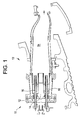
FIG. 1 is a cross-sectional view of an embodiment of a combustor; -
FIG. 2 is an end view of an embodiment of a baffle plate assembly of a combustor; -
FIG. 3 is a partial cross-sectional view of a fuel nozzle of the baffle plate assembly ofFIG. 2 ; -
FIG. 4 is a perspective view of an embodiment of a cover ring that supplies diluent to a plenum defined by the baffle plate assembly ofFIG. 2 ; -
FIG. 5 is a cross-sectional view illustrating an embodiment of a piston ring arrangement of the baffle plate assembly ofFIG. 2 ; and -
FIG. 6 is a perspective view of a locating feature of the piston ring arrangement ofFIG. 5 . - The detailed description explains embodiments of the invention, together with advantages and features, by way of example with reference to the drawings.
- Shown in
FIG. 1 is acombustor 10. Thecombustor 10 includes abaffle plate 12 having sixbaffle holes 14, through which sixfuel nozzles 16 extend, for example, onefuel nozzle 16 extending through eachbaffle hole 14, as best shown inFIG. 2 . While sixfuel nozzles 16 are shown inFIG. 2 , it is to be appreciated that other quantities offuel nozzles 16, for example, one or fourfuel nozzles 16, may be utilized. As shown inFIG. 3 , thebaffle plate 12 and acover ring 18 define aplenum 20 into which adiluent flow 22 is guided via an array of orifices 24 (best shown inFIG. 4 ) in thecover ring 18. In some embodiments, thediluent flow 22 may comprise steam, or other diluents such as nitrogen. - At each
fuel nozzle 16, as shown inFIG. 3 , ashroud 26 is disposed at thebaffle hole 14 between thebaffle plate 12 and thefuel nozzle 16. Theshroud 26 is affixed to thebaffle plate 12 by welding or by other means of attachment such as one or more mechanical fasteners, by brazing, or by adhesives. Theshroud 26 extends circumferentially around thefuel nozzle 16 and is disposed at a radial distance from thefuel nozzle 16 leaving a shroud gap 28 between theshroud 26 and thefuel nozzle 16. In some embodiments, theshroud 26 comprises anattachment flange 30 at which theshroud 26 is affixed to thebaffle plate 12, and anannular flow portion 32 which extends longitudinally along thefuel nozzle 16 defining aflow channel 34 between theflow portion 32 and thefuel nozzle 16. In some embodiments, theflow portion 32 is substantially parallel to thefuel nozzle 16 such that theflow channel 34 has a substantially constant cross-sectional area along anozzle axis 36. As shown inFIG. 5 , the shroud includes apiston ring slot 38 at aninner surface 40 of theflow portion 32, which extends circumferentially around thefuel nozzle 16. One ormore piston rings 42 are disposed in thepiston ring slot 38 and extend radially inwardly toward thefuel nozzle 16 defining apiston ring gap 44 between thefuel nozzle 16 and aninboard portion 46 of the one ormore piston rings 42. Twopiston rings 42 are shown in the embodiment ofFIG. 5 , but it is to be appreciated that other quantities ofpiston rings 42, for example one or threepiston rings 42 may be utilized. - As shown in
FIG. 6 , thepiston rings 42 include at least one locatingtab 48 extending radially inwardly from theinboard portion 46 toward thefuel nozzle 16. Each locatingtab 48 is configured to be received in a corresponding locatingslot 50 in thefuel nozzle 16. When thebaffle plate 12 and the installedpiston rings 42 are assembled to thefuel nozzle 16, the locatingtabs 48 align with the locatingslots 50 and are installed thereto setting a circumferential orientation of thepiston rings 42 around thefuel nozzle 16 and establishing a desiredpiston ring gap 44, which is interrupted at each locatingtab 48 location. Utilizing thepiston rings 42 located by the combination of the locatingtabs 48 and locatingslots 50 establishes a consistentpiston ring gap 44 around eachfuel nozzle 16. - In operation, the
diluent flow 22 is guided from theplenum 20, along the shroud gap 28, and through thepiston ring gap 44. Once through thepiston ring gap 44, thediluent flow 22 is introduced to anexterior 52 of thebaffle plate 12 at ahead end 54 of thecombustor 10, in close proximity to a plurality ofair flow holes 56 in thefuel nozzle 16. At least a portion of thediluent flow 22 enters the plurality ofair flow holes 56 and is mixed with air and fuel in thenozzle 16. Guiding thediluent flow 22 along the shroud gap 28 allows injection of thediluent flow 22 nearby theair flow holes 56 to increase efficiency of thediluent flow 22. Further, thediluent flow 22 is metered via thepiston ring gap 44 and is consistent around thebaffle plate 12 due to the use of the locatingtabs 48 to establish consistentpiston ring gaps 44. Thus, a volume ofdiluent flow 22 required is reduced thereby reducing operability issues such as dynamics and lean blow out. - While the invention has been described in detail in connection with only a limited number of embodiments, it should be readily understood that the invention is not limited to such disclosed embodiments. Rather, the invention can be modified to incorporate any number of variations, alterations, substitutions or equivalent arrangements not heretofore described, but which are commensurate with the spirit and scope of the invention. Additionally, while various embodiments of the invention have been described, it is to be understood that aspects of the invention may include only some of the described embodiments. Accordingly, the invention is not to be seen as limited by the foregoing description, but is only limited by the scope of the appended claims.
Claims (15)
- A combustor (10) comprising:a baffle plate (12) including at least one through baffle hole (14);at least one fuel nozzle (16) extending through the at least one through baffle hole (14);at least one shroud (26) secured to the baffle plate (12) including at least one piston ring (42) disposed at the at least one shroud (26), the at least one piston ring (42) configured to control a flow of diluent between the at least one shroud (26) and the at least one fuel nozzle (16).
- The combustor (10) of Claim 1, wherein the at least one piston ring (42) includes at least one locating feature (48) positionable at a corresponding locating slot (50) in the at least one fuel nozzle (16).
- The combustor (10) of Claim 2, wherein the at least one locating feature (48) sets a piston ring gap (44) between the at least one piston ring (42) and the at least one fuel nozzle (16).
- The combustor of Claim 2, wherein the at least one locating feature is at least one locating tab.
- The combustor of Claim 2, wherein the at least one locating feature is four locating features.
- The combustor of any of the preceding claims, wherein the at least one piston ring is two piston rings.
- The combustor (10) of any of the preceding claims, wherein the at least one shroud (26) and the at least one fuel nozzle (16) define a flow channel (34) therebetween.
- The combustor (10) of Claim 4, wherein the at least one piston ring (42) is disposed at an end of a downstream end of the flow channel (34).
- The combustor of any of the preceding claims, wherein the at least one piston ring is disposed in at least one piston ring slot in the at least one shroud.
- The combustor of any of the preceding claims, wherein the diluent is at least one of steam and/or nitrogen.
- A method for providing diluent to a combustor (10) comprising:providing a piston ring gap (44) defined by at least one piston ring (42) disposed at a baffle plate (12) and a fuel nozzle (16) extending through a through hole in the baffle plate (12); andflowing the diluent through the piston ring gap (44) towards at least one airflow hole in the fuel nozzle (16).
- The method of Claim 11, wherein the diluent (22) is flowed through a flow channel (34) defined by a shroud (26) secured to the baffle plate (12) and the fuel nozzle (16) upstream of the piston ring gap (44).
- The method of Claim 12, wherein the at least one piston ring (42) is disposed in at least one piston ring slot (38) in the shroud (26).
- The method of Claim 11 or 12, wherein at least a portion of the diluent (22) enters the at least one air flow hole in the fuel nozzle (16) downstream of the piston ring gap (44).
- The method of any of Claims 11 to 14, wherein the at least one piston ring (42) includes at least one locating feature (48) positionable at a corresponding locating slot (50) in the fuel nozzle (16).
Applications Claiming Priority (1)
| Application Number | Priority Date | Filing Date | Title |
|---|---|---|---|
| US12/250,875 US9121609B2 (en) | 2008-10-14 | 2008-10-14 | Method and apparatus for introducing diluent flow into a combustor |
Publications (2)
| Publication Number | Publication Date |
|---|---|
| EP2177832A2 true EP2177832A2 (en) | 2010-04-21 |
| EP2177832A3 EP2177832A3 (en) | 2013-08-21 |
Family
ID=41531896
Family Applications (1)
| Application Number | Title | Priority Date | Filing Date |
|---|---|---|---|
| EP09172916.0A Withdrawn EP2177832A3 (en) | 2008-10-14 | 2009-10-13 | Method and apparatus for introducing diluent flow into a combustor |
Country Status (4)
| Country | Link |
|---|---|
| US (1) | US9121609B2 (en) |
| EP (1) | EP2177832A3 (en) |
| JP (1) | JP5507947B2 (en) |
| CN (1) | CN101725976B (en) |
Families Citing this family (8)
| Publication number | Priority date | Publication date | Assignee | Title |
|---|---|---|---|---|
| RU2560099C2 (en) * | 2011-01-31 | 2015-08-20 | Дженерал Электрик Компани | Fuel nozzle (versions) |
| US8448442B2 (en) * | 2011-05-19 | 2013-05-28 | General Electric Company | Flexible combustor fuel nozzle |
| US8966907B2 (en) | 2012-04-16 | 2015-03-03 | General Electric Company | Turbine combustor system having aerodynamic feed cap |
| US9267690B2 (en) * | 2012-05-29 | 2016-02-23 | General Electric Company | Turbomachine combustor nozzle including a monolithic nozzle component and method of forming the same |
| JP6110110B2 (en) | 2012-11-16 | 2017-04-05 | 三菱日立パワーシステムズ株式会社 | Gas turbine and gas turbine operating method |
| DE102013007443A1 (en) * | 2013-04-30 | 2014-10-30 | Rolls-Royce Deutschland Ltd & Co Kg | Burner seal for gas turbine combustor head and heat shield |
| JP6725273B2 (en) * | 2016-03-11 | 2020-07-15 | 三菱日立パワーシステムズ株式会社 | Wing, gas turbine equipped with this |
| US10982593B2 (en) * | 2017-06-16 | 2021-04-20 | General Electric Company | System and method for combusting liquid fuel in a gas turbine combustor with staged combustion |
Family Cites Families (154)
| Publication number | Priority date | Publication date | Assignee | Title |
|---|---|---|---|---|
| US1426815A (en) * | 1921-12-29 | 1922-08-22 | Burgstaller Mathias | Gas burner |
| US1588792A (en) * | 1925-08-29 | 1926-06-15 | Harry H Dodge | Gas burner |
| US1781236A (en) | 1928-04-23 | 1930-11-11 | Lilge Friedrich | Whirl burner |
| US2304397A (en) * | 1939-08-16 | 1942-12-08 | Sinclair Refining Co | Catalytic cracking |
| US2304398A (en) * | 1940-02-08 | 1942-12-08 | Sinclair Refining Co | Catalytic cracking |
| US2413407A (en) * | 1941-12-18 | 1946-12-31 | Bonard Claude | Method of cracking hydrocarbons in the presence of a diluent gas |
| US2812978A (en) | 1955-02-09 | 1957-11-12 | Louis S Billman | Fuel injection system for ramjet aircraft |
| US3087484A (en) * | 1956-06-05 | 1963-04-30 | George D Eddy | Heater and gas burner therefor |
| US3104947A (en) * | 1959-08-25 | 1963-09-24 | Collier Carbon & Chemical Co | Submerged combustion concentration apparatus and process |
| US3195606A (en) * | 1959-12-11 | 1965-07-20 | Minor W Stout | Combustion and heating apparatus |
| US3187799A (en) * | 1961-04-11 | 1965-06-08 | Midland Ross Corp | Self-stabilizing combustion apparatus and method |
| US3580700A (en) * | 1968-11-27 | 1971-05-25 | Thayer C Hinckley | Burner for cigarette lighter |
| US3620013A (en) * | 1969-10-31 | 1971-11-16 | James H Rogers | Noise abatement methods relating to flame and jet production and associated apparatus |
| US3890088A (en) * | 1970-09-17 | 1975-06-17 | Advanced Tech Lab | Apparatus for reducing formation of oxides of nitrogen in combustion processes |
| JPS4931059Y1 (en) | 1970-11-30 | 1974-08-22 | ||
| US3724229A (en) | 1971-02-25 | 1973-04-03 | Pacific Lighting Service Co | Combination liquefied natural gas expansion and desalination apparatus and method |
| US3704762A (en) | 1971-09-16 | 1972-12-05 | Gen Electric | Gas turbine exhaust silencer and support |
| US3747336A (en) | 1972-03-29 | 1973-07-24 | Gen Electric | Steam injection system for a gas turbine |
| US3861858A (en) * | 1972-12-11 | 1975-01-21 | Midland Ross Corp | Throat mix burner |
| US3845620A (en) * | 1973-02-12 | 1974-11-05 | Gen Electric | Cooling film promoter for combustion chambers |
| US3831854A (en) * | 1973-02-23 | 1974-08-27 | Hitachi Ltd | Pressure spray type fuel injection nozzle having air discharge openings |
| DE2356822A1 (en) | 1973-11-14 | 1975-05-15 | Lucas Industries Ltd | Fuel evaporator for gas turbine engines - has two concentric turbulence rings round the nozzle |
| US3869246A (en) | 1973-12-26 | 1975-03-04 | Gen Motors Corp | Variable configuration combustion apparatus |
| JPS5129726A (en) * | 1974-09-06 | 1976-03-13 | Mitsubishi Heavy Ind Ltd | |
| GB1531601A (en) | 1976-02-18 | 1978-11-08 | Foster Wheeler Power Prod | Steam boilers |
| US4322945A (en) | 1980-04-02 | 1982-04-06 | United Technologies Corporation | Fuel nozzle guide heat shield for a gas turbine engine |
| US4365753A (en) | 1980-08-22 | 1982-12-28 | Parker-Hannifin Corporation | Boundary layer prefilmer airblast nozzle |
| GB2085117A (en) | 1980-10-06 | 1982-04-21 | Rolls Royce | Seals |
| SE457041B (en) | 1981-03-05 | 1988-11-21 | Abb Stal Ab | PHASING DEVICE CONTAINS A POWER PLANT WITH PRE-BURNING OF A BRAENLE IN A FLUIDIZED BED. |
| US4569652A (en) * | 1981-12-23 | 1986-02-11 | Toyotomi Kogyo Co., Ltd. | Combustion cylinder construction for oil space heater |
| US4600151A (en) | 1982-11-23 | 1986-07-15 | Ex-Cell-O Corporation | Fuel injector assembly with water or auxiliary fuel capability |
| US4928478A (en) | 1985-07-22 | 1990-05-29 | General Electric Company | Water and steam injection in cogeneration system |
| JPH0754162B2 (en) * | 1986-05-26 | 1995-06-07 | 株式会社日立製作所 | Burner for low NOx combustion |
| JPH01114623A (en) | 1987-10-27 | 1989-05-08 | Toshiba Corp | Gas turbine combustor |
| US5054279A (en) | 1987-11-30 | 1991-10-08 | General Electric Company | Water spray ejector system for steam injected engine |
| US4893468A (en) | 1987-11-30 | 1990-01-16 | General Electric Company | Emissions control for gas turbine engine |
| GB2219070B (en) | 1988-05-27 | 1992-03-25 | Rolls Royce Plc | Fuel injector |
| US5044559A (en) * | 1988-11-02 | 1991-09-03 | United Technologies Corporation | Gas assisted liquid atomizer |
| GB2231651B (en) | 1989-05-18 | 1991-10-16 | Rolls Royce Plc | Injector |
| US5158445A (en) * | 1989-05-22 | 1992-10-27 | Institute Of Gas Technology | Ultra-low pollutant emission combustion method and apparatus |
| US5271216A (en) | 1990-06-19 | 1993-12-21 | Asea Brown Boveri Ltd. | Method for increasing the compressor-related pressure drop of the gas turbine of a power plant |
| US5365865A (en) * | 1991-10-31 | 1994-11-22 | Monro Richard J | Flame stabilizer for solid fuel burner |
| US5284438A (en) | 1992-01-07 | 1994-02-08 | Koch Engineering Company, Inc. | Multiple purpose burner process and apparatus |
| EP0564181B1 (en) | 1992-03-30 | 1996-11-20 | General Electric Company | Combustor dome construction |
| US5634329A (en) | 1992-04-30 | 1997-06-03 | Abb Carbon Ab | Method of maintaining a nominal working temperature of flue gases in a PFBC power plant |
| US5271218A (en) | 1992-05-28 | 1993-12-21 | Gerneral Electric Company | Off-engine mounting system for steam and gaseous fuel manifolds of marine and industrial gas turbine engines |
| IT1263683B (en) | 1992-08-21 | 1996-08-27 | Westinghouse Electric Corp | NOZZLE COMPLEX FOR FUEL FOR A GAS TURBINE |
| IN187412B (en) * | 1992-09-02 | 2002-04-20 | Northern Eng Ind | |
| US5247790A (en) | 1992-09-18 | 1993-09-28 | Westinghouse Electric Corp. | Gas turbine fuel nozzle with replaceable cap |
| CA2088947C (en) | 1993-02-05 | 1996-07-16 | Daniel A. Warkentin | Hydrogen fuelled gas turbine |
| US5285632A (en) | 1993-02-08 | 1994-02-15 | General Electric Company | Low NOx combustor |
| US5329758A (en) | 1993-05-21 | 1994-07-19 | The United States Of America As Represented By The Secretary Of The Navy | Steam-augmented gas turbine |
| US5375409A (en) | 1993-10-08 | 1994-12-27 | Ahlstrom Pyropower, Inc. | Pressurized fluidized bed combined gas turbine and steam turbine power plant with steam injection |
| US5444982A (en) | 1994-01-12 | 1995-08-29 | General Electric Company | Cyclonic prechamber with a centerbody |
| US5457721A (en) | 1994-05-25 | 1995-10-10 | Battelle Memorial Institute | Method and apparatus for improving the performance of a nuclear power electrical generation system |
| US5526386A (en) | 1994-05-25 | 1996-06-11 | Battelle Memorial Institute | Method and apparatus for steam mixing a nuclear fueled electricity generation system |
| DE4427222A1 (en) | 1994-08-01 | 1996-02-08 | Bmw Rolls Royce Gmbh | Heat shield for a gas turbine combustor |
| FR2724217B1 (en) * | 1994-09-07 | 1996-10-25 | Air Liquide | DEVICE FOR SPREADING A FLAME BY COANDA EFFECT AND OVEN COMPRISING THIS DEVICE |
| US5581999A (en) | 1994-12-15 | 1996-12-10 | United Technologies Corporation | Bulkhead liner with raised lip |
| DE4446862C2 (en) | 1994-12-27 | 1998-01-29 | Siemens Ag | Method for cooling the coolant of a gas turbine and device for carrying out the method |
| US5623827A (en) | 1995-01-26 | 1997-04-29 | General Electric Company | Regenerative cooled dome assembly for a gas turbine engine combustor |
| DE19508111A1 (en) | 1995-03-08 | 1996-09-12 | Bmw Rolls Royce Gmbh | Heat shield arrangement for a gas turbine combustor |
| US5680823A (en) * | 1995-03-22 | 1997-10-28 | The Babcock & Wilcox Company | Short flame XCL burner |
| EP0747635B1 (en) | 1995-06-05 | 2003-01-15 | Rolls-Royce Corporation | Dry low oxides of nitrogen lean premix module for industrial gas turbine engines |
| US5813232A (en) | 1995-06-05 | 1998-09-29 | Allison Engine Company, Inc. | Dry low emission combustor for gas turbine engines |
| US5946917A (en) | 1995-06-12 | 1999-09-07 | Siemens Aktiengesellschaft | Catalytic combustion chamber operating on preformed fuel, preferably for a gas turbine |
| ATE170968T1 (en) * | 1995-07-20 | 1998-09-15 | Dvgw Ev | METHOD AND DEVICE FOR SUPPRESSING FLAME/PRESSURE VIBRATIONS DURING A FIRING |
| BE1010251A4 (en) | 1995-10-20 | 1998-04-07 | Oxipar Sprl | Method for partial oxidation catalyst on fuel gas turbine in combined energy systems and device for its implementation. |
| US5784875A (en) | 1995-11-27 | 1998-07-28 | Innovative Control Systems, Inc. | Water injection into a gas turbine using purge air |
| JP2767403B2 (en) | 1995-11-30 | 1998-06-18 | 科学技術庁航空宇宙技術研究所長 | Low NOx burner for gas turbine |
| US6267585B1 (en) | 1995-12-19 | 2001-07-31 | Daimlerchrysler Aerospace Airbus Gmbh | Method and combustor for combusting hydrogen |
| US6047550A (en) | 1996-05-02 | 2000-04-11 | General Electric Co. | Premixing dry low NOx emissions combustor with lean direct injection of gas fuel |
| US5930990A (en) | 1996-05-14 | 1999-08-03 | The Dow Chemical Company | Method and apparatus for achieving power augmentation in gas turbines via wet compression |
| US5867977A (en) | 1996-05-14 | 1999-02-09 | The Dow Chemical Company | Method and apparatus for achieving power augmentation in gas turbines via wet compression |
| US5861600A (en) | 1996-08-21 | 1999-01-19 | Jensen; Donald C. | Fuel plasma vortex combustion system |
| FR2753779B1 (en) | 1996-09-26 | 1998-10-16 | AERODYNAMIC INJECTION SYSTEM FOR A FUEL AIR MIXTURE | |
| US5697306A (en) * | 1997-01-28 | 1997-12-16 | The Babcock & Wilcox Company | Low NOx short flame burner with control of primary air/fuel ratio for NOx reduction |
| JP3344694B2 (en) * | 1997-07-24 | 2002-11-11 | 株式会社日立製作所 | Pulverized coal combustion burner |
| GB2328011A (en) | 1997-08-05 | 1999-02-10 | Europ Gas Turbines Ltd | Combustor for gas or liquid fuelled turbine |
| US6003299A (en) | 1997-11-26 | 1999-12-21 | Solar Turbines | System for modulating air flow through a gas turbine fuel injector |
| US6047539A (en) | 1998-04-30 | 2000-04-11 | General Electric Company | Method of protecting gas turbine combustor components against water erosion and hot corrosion |
| US6748733B2 (en) | 1998-09-15 | 2004-06-15 | Robert F. Tamaro | System for waste heat augmentation in combined cycle plant through combustor gas diversion |
| US6089024A (en) | 1998-11-25 | 2000-07-18 | Elson Corporation | Steam-augmented gas turbine |
| JP4337960B2 (en) | 1998-12-17 | 2009-09-30 | ゼネラル・エレクトリック・カンパニイ | Apparatus and method for supplying auxiliary steam in a combined cycle system |
| JP3457907B2 (en) | 1998-12-24 | 2003-10-20 | 三菱重工業株式会社 | Dual fuel nozzle |
| FR2788108B1 (en) * | 1998-12-30 | 2001-04-27 | Air Liquide | INJECTOR FOR BURNER AND INJECTION SYSTEM THEREOF |
| ITMI991204A1 (en) | 1999-05-31 | 2000-12-01 | Nuovo Pignone Spa | LIQUID FUEL INJECTOR FOR GAS TURBINE BURNERS |
| US6393823B1 (en) | 1999-11-05 | 2002-05-28 | General Electric Company | Methods for fuel nozzle staging for gas turbine engines |
| US6293088B1 (en) | 1999-11-29 | 2001-09-25 | Siemens Westinghouse Power Corporation | Gas turbine with steam cooling and fuel atomization |
| US6286300B1 (en) | 2000-01-27 | 2001-09-11 | Honeywell International Inc. | Combustor with fuel preparation chambers |
| US6983605B1 (en) | 2000-04-07 | 2006-01-10 | General Electric Company | Methods and apparatus for reducing gas turbine engine emissions |
| US6526758B2 (en) | 2000-05-12 | 2003-03-04 | General Electric Company | Method and apparatus for power augmentation for gas turbine power cycles |
| US6298667B1 (en) | 2000-06-22 | 2001-10-09 | General Electric Company | Modular combustor dome |
| US6729874B2 (en) * | 2000-07-27 | 2004-05-04 | John Zink Company, Llc | Venturi cluster, and burners and methods employing such cluster |
| US6370862B1 (en) | 2000-08-11 | 2002-04-16 | Cheng Power Systems, Inc. | Steam injection nozzle design of gas turbine combustion liners for enhancing power output and efficiency |
| WO2002021044A1 (en) * | 2000-09-07 | 2002-03-14 | John Zink Company, L.L.C. | High capacity/low nox radiant wall burner |
| US6360776B1 (en) | 2000-11-01 | 2002-03-26 | Rolls-Royce Corporation | Apparatus for premixing in a gas turbine engine |
| ATE306050T1 (en) * | 2001-01-04 | 2005-10-15 | Haldor Topsoe As | SWIRL BURNER |
| US6530224B1 (en) | 2001-03-28 | 2003-03-11 | General Electric Company | Gas turbine compressor inlet pressurization system and method for power augmentation |
| US6499303B1 (en) | 2001-04-18 | 2002-12-31 | General Electric Company | Method and system for gas turbine power augmentation |
| US6405521B1 (en) | 2001-05-23 | 2002-06-18 | General Electric Company | Gas turbine power augmentation injection system and related method |
| US6497105B1 (en) | 2001-06-04 | 2002-12-24 | Pratt & Whitney Canada Corp. | Low cost combustor burner collar |
| US6565361B2 (en) * | 2001-06-25 | 2003-05-20 | John Zink Company, Llc | Methods and apparatus for burning fuel with low NOx formation |
| JP3970244B2 (en) * | 2001-07-10 | 2007-09-05 | 三菱重工業株式会社 | Premixing nozzle and combustor and gas turbine |
| US20030013053A1 (en) * | 2001-07-11 | 2003-01-16 | Cornel Dutescu | Waste and toxic gas combustion reactor |
| US6755024B1 (en) | 2001-08-23 | 2004-06-29 | Delavan Inc. | Multiplex injector |
| US7357820B2 (en) * | 2001-09-05 | 2008-04-15 | Webasto Ag | System for converting fuel and air into reformate |
| US6609380B2 (en) | 2001-12-28 | 2003-08-26 | General Electric Company | Liquid fuel nozzle apparatus with passive protective purge |
| US6986658B2 (en) * | 2002-03-16 | 2006-01-17 | Exxonmobil Chemical Patents, Inc. | Burner employing steam injection |
| US6779333B2 (en) | 2002-05-21 | 2004-08-24 | Conocophillips Company | Dual fuel power generation system |
| US20050255416A1 (en) * | 2002-07-19 | 2005-11-17 | Frank Haase | Use of a blue flame burner |
| US7143583B2 (en) | 2002-08-22 | 2006-12-05 | Hitachi, Ltd. | Gas turbine combustor, combustion method of the gas turbine combustor, and method of remodeling a gas turbine combustor |
| US6782703B2 (en) | 2002-09-11 | 2004-08-31 | Siemens Westinghouse Power Corporation | Apparatus for starting a combined cycle power plant |
| US7670569B2 (en) * | 2003-06-13 | 2010-03-02 | Mobotec Usa, Inc. | Combustion furnace humidification devices, systems & methods |
| US7104069B2 (en) | 2003-06-25 | 2006-09-12 | Power Systems Mfg., Llc | Apparatus and method for improving combustion stability |
| JP4150968B2 (en) * | 2003-11-10 | 2008-09-17 | 株式会社日立製作所 | Solid fuel burner and combustion method of solid fuel burner |
| US7104070B2 (en) | 2004-03-04 | 2006-09-12 | General Electric Company | Liquid fuel nozzle apparatus with passive water injection purge |
| US7185497B2 (en) | 2004-05-04 | 2007-03-06 | Honeywell International, Inc. | Rich quick mix combustion system |
| US7007477B2 (en) * | 2004-06-03 | 2006-03-07 | General Electric Company | Premixing burner with impingement cooled centerbody and method of cooling centerbody |
| US7390189B2 (en) * | 2004-08-16 | 2008-06-24 | Air Products And Chemicals, Inc. | Burner and method for combusting fuels |
| US7140189B2 (en) | 2004-08-24 | 2006-11-28 | Pratt & Whitney Canada Corp. | Gas turbine floating collar |
| US7000396B1 (en) | 2004-09-02 | 2006-02-21 | General Electric Company | Concentric fixed dilution and variable bypass air injection for a combustor |
| FR2875584B1 (en) | 2004-09-23 | 2009-10-30 | Snecma Moteurs Sa | EFFERVESCENCE INJECTOR FOR AEROMECHANICAL AIR / FUEL INJECTION SYSTEM IN A TURBOMACHINE COMBUSTION CHAMBER |
| US7228682B2 (en) | 2004-12-16 | 2007-06-12 | Yefim Kashler | System for augmented electric power generation with distilled water output |
| JP4309853B2 (en) * | 2005-01-05 | 2009-08-05 | バブコック日立株式会社 | Solid fuel burner and combustion method |
| US7395670B1 (en) | 2005-02-18 | 2008-07-08 | Praxair Technology, Inc. | Gas turbine fuel preparation and introduction method |
| US20060246388A1 (en) * | 2005-04-29 | 2006-11-02 | Hauck Manufacturing Company | Reduced NOx method of combustion |
| JP4728176B2 (en) | 2005-06-24 | 2011-07-20 | 株式会社日立製作所 | Burner, gas turbine combustor and burner cooling method |
| US7536862B2 (en) | 2005-09-01 | 2009-05-26 | General Electric Company | Fuel nozzle for gas turbine engines |
| EP1767855A1 (en) | 2005-09-27 | 2007-03-28 | Siemens Aktiengesellschaft | Combustion Chamber and Gas Turbine Plant |
| DE102005053819A1 (en) * | 2005-11-11 | 2007-05-16 | Khd Humboldt Wedag Gmbh | Rotary kiln burner |
| FR2893390B1 (en) | 2005-11-15 | 2011-04-01 | Snecma | BOTTOM OF COMBUSTION CHAMBER WITH VENTILATION |
| US7677472B2 (en) * | 2005-12-08 | 2010-03-16 | General Electric Company | Drilled and integrated secondary fuel nozzle and manufacturing method |
| JP4645972B2 (en) * | 2005-12-14 | 2011-03-09 | 修 廣田 | Injection flame burner and furnace, and flame generation method |
| US8122721B2 (en) | 2006-01-04 | 2012-02-28 | General Electric Company | Combustion turbine engine and methods of assembly |
| US8075305B2 (en) * | 2006-01-24 | 2011-12-13 | Exxonmobil Chemical Patents Inc. | Dual fuel gas-liquid burner |
| US7909601B2 (en) * | 2006-01-24 | 2011-03-22 | Exxonmobil Chemical Patents Inc. | Dual fuel gas-liquid burner |
| US7901204B2 (en) * | 2006-01-24 | 2011-03-08 | Exxonmobil Chemical Patents Inc. | Dual fuel gas-liquid burner |
| US20070234735A1 (en) | 2006-03-28 | 2007-10-11 | Mosbacher David M | Fuel-flexible combustion sytem and method of operation |
| FR2899314B1 (en) | 2006-03-30 | 2008-05-09 | Snecma Sa | DEVICE FOR INJECTING A MIXTURE OF AIR AND FUEL, COMBUSTION CHAMBER AND TURBOMACHINE HAVING SUCH A DEVICE |
| US8113824B2 (en) * | 2006-06-01 | 2012-02-14 | Babcock & Wilcox Power Generation Group, Inc. | Large diameter mid-zone air separation cone for expanding IRZ |
| FR2903169B1 (en) | 2006-06-29 | 2011-11-11 | Snecma | DEVICE FOR INJECTING A MIXTURE OF AIR AND FUEL, COMBUSTION CHAMBER AND TURBOMACHINE HAVING SUCH A DEVICE |
| US7810333B2 (en) | 2006-10-02 | 2010-10-12 | General Electric Company | Method and apparatus for operating a turbine engine |
| WO2008047825A1 (en) | 2006-10-20 | 2008-04-24 | Ihi Corporation | Gas turbine combustor |
| US7681398B2 (en) | 2006-11-17 | 2010-03-23 | Pratt & Whitney Canada Corp. | Combustor liner and heat shield assembly |
| US20090013968A1 (en) | 2007-07-09 | 2009-01-15 | Keegan Kevin R | Vapor recovery system for a direct injector fuel rail assembly |
| FR2918716B1 (en) | 2007-07-12 | 2014-02-28 | Snecma | OPTIMIZATION OF ANTI-COKE FILM IN AN INJECTION SYSTEM |
| US7861528B2 (en) * | 2007-08-21 | 2011-01-04 | General Electric Company | Fuel nozzle and diffusion tip therefor |
| US8291705B2 (en) * | 2008-08-13 | 2012-10-23 | General Electric Company | Ultra low injection angle fuel holes in a combustor fuel nozzle |
| US20110183274A1 (en) * | 2008-08-26 | 2011-07-28 | Michael Bahn | Producing ageing gas for exhaust gas after-treatment systems |
| US20100089020A1 (en) * | 2008-10-14 | 2010-04-15 | General Electric Company | Metering of diluent flow in combustor |
| US8567199B2 (en) * | 2008-10-14 | 2013-10-29 | General Electric Company | Method and apparatus of introducing diluent flow into a combustor |
| US20100089022A1 (en) * | 2008-10-14 | 2010-04-15 | General Electric Company | Method and apparatus of fuel nozzle diluent introduction |
| US8347631B2 (en) * | 2009-03-03 | 2013-01-08 | General Electric Company | Fuel nozzle liquid cartridge including a fuel insert |
-
2008
- 2008-10-14 US US12/250,875 patent/US9121609B2/en not_active Expired - Fee Related
-
2009
- 2009-10-09 JP JP2009234696A patent/JP5507947B2/en not_active Expired - Fee Related
- 2009-10-13 EP EP09172916.0A patent/EP2177832A3/en not_active Withdrawn
- 2009-10-14 CN CN200910174099.6A patent/CN101725976B/en not_active Expired - Fee Related
Also Published As
| Publication number | Publication date |
|---|---|
| US20100092896A1 (en) | 2010-04-15 |
| CN101725976B (en) | 2014-03-05 |
| JP5507947B2 (en) | 2014-05-28 |
| JP2010096177A (en) | 2010-04-30 |
| CN101725976A (en) | 2010-06-09 |
| US9121609B2 (en) | 2015-09-01 |
| EP2177832A3 (en) | 2013-08-21 |
Similar Documents
| Publication | Publication Date | Title |
|---|---|---|
| US8567199B2 (en) | Method and apparatus of introducing diluent flow into a combustor | |
| US8454350B2 (en) | Diluent shroud for combustor | |
| US9121609B2 (en) | Method and apparatus for introducing diluent flow into a combustor | |
| EP2831505B1 (en) | Turbomachine combustor assembly | |
| EP2525151B1 (en) | Combustor assembly for a turbomachine | |
| CN101082422B (en) | Inlet flow conditioner for gas turbine engine fuel nozzle | |
| CN101476725B (en) | Integrated fuel nozzle IFC | |
| JP2019023550A (en) | Method of use in dual fuel injectors and gas turbine combustors | |
| EP2177831A2 (en) | Method and apparatus of fuel nozzle diluent introduction | |
| US20100089020A1 (en) | Metering of diluent flow in combustor | |
| US8661825B2 (en) | Pegless secondary fuel nozzle including a unitary fuel injection manifold | |
| US10808623B2 (en) | Combustion chamber assembly with burner seal and nozzle as well as guiding flow generating equipment | |
| EP3667168B1 (en) | Injection system with radial in-flow swirl premix gas fuel injectors |
Legal Events
| Date | Code | Title | Description |
|---|---|---|---|
| PUAI | Public reference made under article 153(3) epc to a published international application that has entered the european phase |
Free format text: ORIGINAL CODE: 0009012 |
|
| AK | Designated contracting states |
Kind code of ref document: A2 Designated state(s): AT BE BG CH CY CZ DE DK EE ES FI FR GB GR HR HU IE IS IT LI LT LU LV MC MK MT NL NO PL PT RO SE SI SK SM TR |
|
| AX | Request for extension of the european patent |
Extension state: AL BA RS |
|
| PUAL | Search report despatched |
Free format text: ORIGINAL CODE: 0009013 |
|
| AK | Designated contracting states |
Kind code of ref document: A3 Designated state(s): AT BE BG CH CY CZ DE DK EE ES FI FR GB GR HR HU IE IS IT LI LT LU LV MC MK MT NL NO PL PT RO SE SI SK SM TR |
|
| AX | Request for extension of the european patent |
Extension state: AL BA RS |
|
| RIC1 | Information provided on ipc code assigned before grant |
Ipc: F23R 3/28 20060101ALI20130716BHEP Ipc: F23R 3/04 20060101AFI20130716BHEP |
|
| 17P | Request for examination filed |
Effective date: 20140221 |
|
| RBV | Designated contracting states (corrected) |
Designated state(s): AT BE BG CH CY CZ DE DK EE ES FI FR GB GR HR HU IE IS IT LI LT LU LV MC MK MT NL NO PL PT RO SE SI SK SM TR |
|
| RIC1 | Information provided on ipc code assigned before grant |
Ipc: F23R 3/04 20060101AFI20140326BHEP Ipc: F23R 3/28 20060101ALI20140326BHEP Ipc: F23R 3/60 20060101ALI20140326BHEP Ipc: F23R 3/44 20060101ALI20140326BHEP Ipc: F23L 7/00 20060101ALI20140326BHEP |
|
| GRAP | Despatch of communication of intention to grant a patent |
Free format text: ORIGINAL CODE: EPIDOSNIGR1 |
|
| INTG | Intention to grant announced |
Effective date: 20140513 |
|
| STAA | Information on the status of an ep patent application or granted ep patent |
Free format text: STATUS: THE APPLICATION IS DEEMED TO BE WITHDRAWN |
|
| 18D | Application deemed to be withdrawn |
Effective date: 20140924 |