EP2177713A1 - Appareil et procédés pour améliorer la mise en place d'un bouchon de ciment - Google Patents
Appareil et procédés pour améliorer la mise en place d'un bouchon de ciment Download PDFInfo
- Publication number
- EP2177713A1 EP2177713A1 EP08167065A EP08167065A EP2177713A1 EP 2177713 A1 EP2177713 A1 EP 2177713A1 EP 08167065 A EP08167065 A EP 08167065A EP 08167065 A EP08167065 A EP 08167065A EP 2177713 A1 EP2177713 A1 EP 2177713A1
- Authority
- EP
- European Patent Office
- Prior art keywords
- sensor
- pipe
- well
- cable
- sensor package
- Prior art date
- Legal status (The legal status is an assumption and is not a legal conclusion. Google has not performed a legal analysis and makes no representation as to the accuracy of the status listed.)
- Withdrawn
Links
- 239000004568 cement Substances 0.000 title claims abstract description 55
- 238000000034 method Methods 0.000 title claims abstract description 21
- 239000012530 fluid Substances 0.000 claims description 17
- 239000002002 slurry Substances 0.000 claims description 11
- 238000004873 anchoring Methods 0.000 claims description 7
- 238000005086 pumping Methods 0.000 claims description 3
- 238000005259 measurement Methods 0.000 abstract description 15
- 238000004891 communication Methods 0.000 description 11
- 238000005553 drilling Methods 0.000 description 8
- 238000011109 contamination Methods 0.000 description 7
- 239000006187 pill Substances 0.000 description 6
- 238000009530 blood pressure measurement Methods 0.000 description 5
- 125000006850 spacer group Chemical group 0.000 description 5
- 239000000835 fiber Substances 0.000 description 3
- 239000000463 material Substances 0.000 description 3
- 238000009529 body temperature measurement Methods 0.000 description 2
- 239000007788 liquid Substances 0.000 description 2
- 239000011398 Portland cement Substances 0.000 description 1
- 230000003213 activating effect Effects 0.000 description 1
- IQYKECCCHDLEPX-UHFFFAOYSA-N chloro hypochlorite;magnesium Chemical compound [Mg].ClOCl IQYKECCCHDLEPX-UHFFFAOYSA-N 0.000 description 1
- 239000004020 conductor Substances 0.000 description 1
- 238000006073 displacement reaction Methods 0.000 description 1
- 239000003822 epoxy resin Substances 0.000 description 1
- 238000011156 evaluation Methods 0.000 description 1
- 229920000876 geopolymer Polymers 0.000 description 1
- LNEPOXFFQSENCJ-UHFFFAOYSA-N haloperidol Chemical compound C1CC(O)(C=2C=CC(Cl)=CC=2)CCN1CCCC(=O)C1=CC=C(F)C=C1 LNEPOXFFQSENCJ-UHFFFAOYSA-N 0.000 description 1
- 230000000977 initiatory effect Effects 0.000 description 1
- 238000001139 pH measurement Methods 0.000 description 1
- 229920000647 polyepoxide Polymers 0.000 description 1
- 230000000630 rising effect Effects 0.000 description 1
- 239000000523 sample Substances 0.000 description 1
- 230000035945 sensitivity Effects 0.000 description 1
- 239000007787 solid Substances 0.000 description 1
- 238000012360 testing method Methods 0.000 description 1
- 230000008719 thickening Effects 0.000 description 1
Images


Classifications
-
- E—FIXED CONSTRUCTIONS
- E21—EARTH OR ROCK DRILLING; MINING
- E21B—EARTH OR ROCK DRILLING; OBTAINING OIL, GAS, WATER, SOLUBLE OR MELTABLE MATERIALS OR A SLURRY OF MINERALS FROM WELLS
- E21B33/00—Sealing or packing boreholes or wells
- E21B33/10—Sealing or packing boreholes or wells in the borehole
- E21B33/13—Methods or devices for cementing, for plugging holes, crevices or the like
-
- E—FIXED CONSTRUCTIONS
- E21—EARTH OR ROCK DRILLING; MINING
- E21B—EARTH OR ROCK DRILLING; OBTAINING OIL, GAS, WATER, SOLUBLE OR MELTABLE MATERIALS OR A SLURRY OF MINERALS FROM WELLS
- E21B47/00—Survey of boreholes or wells
- E21B47/06—Measuring temperature or pressure
-
- E—FIXED CONSTRUCTIONS
- E21—EARTH OR ROCK DRILLING; MINING
- E21B—EARTH OR ROCK DRILLING; OBTAINING OIL, GAS, WATER, SOLUBLE OR MELTABLE MATERIALS OR A SLURRY OF MINERALS FROM WELLS
- E21B47/00—Survey of boreholes or wells
- E21B47/08—Measuring diameters or related dimensions at the borehole
Definitions
- This invention relates to a method and apparatus for use during cement plug placement operations of the type encountered in wells in the oil and gas industry.
- the invention relates to methods using instrumented pipes and downhole sensors.
- Cement plugs are placed in wellbores for a variety of reasons; for curing wellbore instability or losses, plugging a wellbore or a portion of it, abandoning a wellbore or a section of it, providing a base for initiating a deviation or kick-off and more.
- Cement plugs are constructed by pumping a relatively small amount of cement slurry down a drill pipe where it later sets solid.
- Figure 1 shows a section of a well in which a cement plug is being set.
- the well 10 has a viscous pill 12 set in the well 10 at the bottom of the desired plug location.
- the end of a drill pipe 14 is then positioned just above the pill 12 and cement 16 is pumped down the drill pipe 14 into the well to form the plug 18 on the pill 12.
- the drill pipe is pulled back so that it does not remain in the plug 18 when it sets.
- the drill pipe 14 can be withdrawn and other operations continued.
- a further problem is the risk of contamination, which leads to the cement not setting in the desired period of time and not achieving the required strength.
- the cement slurry may initially become contaminated whilst being pumped into the drill pipe and later when being jetted in the underlying drilling fluid.
- Some contamination also occurs in the drill pipe or casing annulus as the displacement of the drilling fluid is seldom perfect as the drill pipe is not centralized and some mud is trapped on the low or narrow side.
- This invention seeks to overcome many of the challenges highlighted above by providing real-time measurements of wellbore properties during cement plug placement.
- a first aspect of the invention provides an apparatus for placing a cement plug in a well, comprising:
- the senor can perform a calliper measurement for indicating hole diameter as the pipe is run into the well and or measure the viscosity of fluids in the well in the region of the predetermined location.
- Another embodiment comprises differential pressure sensor, for example a distributed differential pressure sensor for measuring pressure in the annulus outside the pipe in the well to evaluate the density of the fluids therein, or for measuring the difference in pressure between the inside of the pipe and annulus outside the pipe in the well.
- a particularly preferred embodiment of the invention comprises a temperature sensor.
- the apparatus can comprise a sensor package that is detachable from the pipe so as to remain at the predetermined location in the well and houses a sensor cable which can be withdrawn to connect the sensor to the operating system at the surface.
- the sensor cable can be connected to the pipe such that withdrawal of the pipe from the well causes the sensor cable to be withdrawn from the sensor package.
- the sensor cable can also be connected to a cable extending along the pipe to the operating system at the surface.
- the apparatus preferably further comprises a release mechanism by which the sensor package is held in the pipe, the mechanism being operable by means of a body that can be pumped through the pipe to detach the sensor package on contact with the mechanism.
- An anchoring system can be provided for securing the sensor package in position in the well after it is detached from the pipe.
- a second aspect of the invention provides method of placing a cement plug in a well, comprising:
- the step of operating the sensor can comprise making a calliper measurement of the well, at least in the region of the predetermined location, to determine the diameter of the well, measuring the density of fluids in the well in the region of the predetermined location, making a temperature measurement, and/or obtaining a differential pressure measurement in the fluids in the well in region of predetermined location.
- the step of obtaining differential pressure measurements can comprise making a distributed differential pressure measurement in the annulus in the well outside the pipe to determine the density of fluids in the annulus; or measuring the pressure difference between the inside and the outside of the pipe when located in the well.
- the method can further comprise detaching the sensor package from the pipe so that it remains at the predetermined location in the well, and withdrawing the pipe.
- the step of withdrawing the pipe from the well acts to withdraw the sensor cable from the sensor package.
- the sensor cable can be connected to a cable extending along the pipe to the operating system at the surface.
- the sensor package is held in the pipe by a release mechanism, the method comprising pumping a body through the pipe to contact the mechanism to detach the sensor package.
- the sensor package can also comprise an anchoring system, the method comprising securing the sensor package in position in the well after it is detached from the pipe by operating the anchoring system.
- the method according to the second aspect of the invention is preferably performed using an apparatus according to the first aspect of the invention.
- the cement can comprise Portland cement, magnesium oxychloride cement, epoxy resins, geopolymers, etc.
- Figure 2 shows a first embodiment of the invention, in which the lower end of the drill pipe 14 is provided with a downhole measurement package 20 comprising one or more sensors for measuring parameters in the well.
- the sensor package is connected back to the surface by means of a wire or cable 22.
- the wire or cable 22 can be run along the inside or outside of the drill pipe 14, and connects to an operating system 24 at the surface.
- the cable 22 need not be continuous, wireless communication systems can be provided for at least part of the connection to the surface such as at pipe joints (see US7019665 ).
- the sensors in the downhole measurement package can measure various parameters.
- Including a sonic (or other) calliper measurement on the wired pipe 14 can give an accurate indication of the well diameter while running in to place the cement plug. This will allow the spacer and cement volumes to be recalculated to minimise mixing (optimise interfaces while pulling out) without loss of rig timesince a separate wireline calliper run is may not be required.
- a temperature measurement can give an idea of how long to wait on cement. Sensitivity tests on the cement thickening time beforehand will lead to optimised waiting time.
- a downhole viscosity measurement can allow the quality of the viscous plug to be evaluated. If it is insufficient a second viscous pill can be placed prior to placing cement, thus minimising the risk of slumping.
- a distributed differential pressure measurement in the annulus can allow the fluid density in the annulus to be determined and if there is sufficient density difference between the fluids (spacer and cement/spacer and mud) it will be possible to qualitatively determine the degree of contamination of one fluid by another. If the contamination is too high, the decision can be taken to redo the plug immediately instead of waiting for the cement to set.
- a differential pressure measurement between the inside and the outside of drill pipe 14 can indicate if the operation is following plan.
- a placement model of the plug allows calculation of the ideal dp as a function of job time. This can allow real time matching and evaluation of the job. Specifically if the same fluid is lying both inside and outside the drill pipe 14 at the depth of the DP measurement, no differential pressure will be measured; when a fluid interface arrives at the level of one pressure port - either inside or outside the drill-pipe - a pressure difference will be measured that is a function of the fluid densities; the pressure difference will increase as the pipe is pulled out.
- a temperature (or other) probe can be dropped into the cement as the drill pipe 14 is being pulled out. This can be connected via thin conductor or fibre optic to the wired pipe 14.
- the temperature monitor can allow indication of cement setting and pull out at the earliest time. This is particularly applicable to wells where the pipe is not pulled out on a routine basis during the setting.
- a further embodiment of the invention provides a method of optimising cement plug placement by use of a wired placement conduit.
- a sensor package is deployed into the cement plug while in its liquid state prior to setting to take measurements of down hole properties.
- the method comprises assembly and deployment of the wired placement conduit which permits the correct placement of the sensor package and the unrolling of the communication wire and deployment of the slurry placement device which activates the release of the sensor package.
- the wire can be coiled on the conduit/drill pipe, from which it would unroll as the pipe is withdrawn.
- the wired placement conduit is assembled on the surface prior to deployment.
- the sensor package and communication wire rolled as a bobbin are subsequently fastened to the lower end of the wired placement conduit.
- the wired placement conduit is lowered downhole prior to the cement slurry being pumped.
- the slurry placement device is launched from the surface through the wired placement conduit thus activating the release of the sensor package.
- the release of the sensor package generates a pressure pulse.
- the wired placement conduit is retracted to the surface in response to the pressure pulse.
- the wired placement conduit may be partially retracted at a distance sufficient to ensure that the end is clear of the setting material.
- the communication wire is unrolled to the surface in response to the pressure pulse.
- the sensor package is capable of measuring downhole properties in a similar manner to that described above. These include but are not limited to; temperature, viscosity, density, pH, resistivity measurements, differential pressure, elastic modulus and acoustic impedance.
- the sensor package may comprise multiple distributed sensors along the cement plug length. The data obtained from the sensor package can be used to manage the operation. For example, a viscous pill may be used in response to obtaining a low viscosity measurement indicative of slumping.
- the sensor package may be attached to the well at the desired depth by a securing device.
- the securing device may comprise arms which permit contact with the well walls.
- the wired pipe may comprise a drill string.
- the wired pipe may comprise coiled tubing.
- Devices located on the wired placement conduit permit the measurement of the hole diameter. Sonic measurements may be taken to determine hole diameter. Alternatively callipers may be incorporated to measure hole diameter.
- the communication wire may comprise a fibre optic cable and/or an electrical cable.
- This invention provides a method and apparatus for deploying sensors into the liquid cement plug immediately following its placement and until it is almost set. As the material evolves with time, an operator can follow in real time its actual properties. This enables the operator to make informed decisions, based on these measured properties, of when it is possible to resume drilling operations. The amount of unproductive time is minimised.
- Figure 3 shows the wired placement conduit 30 being deployed down the wellbore 32.
- the wired placement conduit Prior to the wired placement conduit being lowered downhole it is assembled at the surface with the sensor package 34 and communication wire 36 rolled as a bobbin fastened to the lower end of the wired pipe 30.
- the wired placement conduit may be either a drill string or coiled tubing.
- the wired placement conduit is lowered into the hole 32 and the cement slurry is pumped.
- the slurry placement device 40 is launched from the surface through the wired placement conduit.
- the slurry placement device may comprise a dart, ball or other similar device.
- the slurry placement device 40 hits a seat which activates the release of the sensor package.
- a pressure pulse may be generated and received at the surface providing a positive indication of the release of the sensor package.
- Figure 4 shows the retraction of the wired placement conduit 30 and unrolling of the communication wire 36; this occurs in response to the reception of the pressure pulse.
- the sensor package 34 is released the wired pipe 30 is progressively pulled out of the hole 32.
- the communication wire 36 unrolls until it reaches the surface.
- the communication wire 36 may be an electrical wire, a fibre optic or a combination of both.
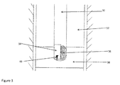
- Figure 5 shows an alternative embodiment of the invention whereby the wired placement conduit 30 may only be pulled up a certain distance to ensure that the end is clear of the setting material 38 while the sensor package 34 remains in contact with it.
- the communication wire 36 connects to the wired placement conduit 30 and the signal is transmitted through the wired placement conduit 30 to the surface. This embodiment eliminates the need to retract the wired placement conduit 30 completely to the surface.
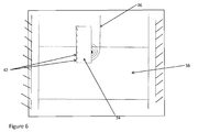
- Figure 6 shows the sensor package 34 released and deployed to the cement plug 38.
- the sensor package 34 is capable of measuring downhole properties. These include but are not limited to; temperature, viscosity, density, pH, differential pressure, elastic modulus and acoustic impedance.
- the sensor package 34 may comprise multiple sensors 42 distributed along the cement plug length.
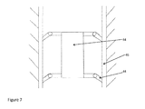
- Figure 7 shows the sensor package 34 being secured to the borehole 32 at the required depth by means of a securing device.
- the deployment of anchoring arms 44 permits contact to be made with the well casing 46 to hold the package 34 in place. This avoids the package sinking out of the plug or rising to its surface, or becoming displaced by contact with other equipment.
Landscapes
- Geology (AREA)
- Mining & Mineral Resources (AREA)
- Life Sciences & Earth Sciences (AREA)
- Engineering & Computer Science (AREA)
- Physics & Mathematics (AREA)
- General Life Sciences & Earth Sciences (AREA)
- Fluid Mechanics (AREA)
- Environmental & Geological Engineering (AREA)
- Geochemistry & Mineralogy (AREA)
- Geophysics (AREA)
- Measuring Arrangements Characterized By The Use Of Fluids (AREA)
- Measurement Of Levels Of Liquids Or Fluent Solid Materials (AREA)
- Investigating Or Analyzing Materials By The Use Of Electric Means (AREA)
- Measuring Fluid Pressure (AREA)
- Investigating Strength Of Materials By Application Of Mechanical Stress (AREA)
Priority Applications (4)
| Application Number | Priority Date | Filing Date | Title |
|---|---|---|---|
| EP08167065A EP2177713A1 (fr) | 2008-10-20 | 2008-10-20 | Appareil et procédés pour améliorer la mise en place d'un bouchon de ciment |
| GB1105750.2A GB2476206B (en) | 2008-10-20 | 2009-09-30 | Methods and apparatus for improved cement plug placement |
| PCT/EP2009/007064 WO2010046021A1 (fr) | 2008-10-20 | 2009-09-30 | Procédés et appareil pour le positionnement d’un bouchon de ciment amélioré |
| US13/124,294 US8826979B2 (en) | 2008-10-20 | 2009-09-30 | Methods and apparatus for improved cement plug placement |
Applications Claiming Priority (1)
| Application Number | Priority Date | Filing Date | Title |
|---|---|---|---|
| EP08167065A EP2177713A1 (fr) | 2008-10-20 | 2008-10-20 | Appareil et procédés pour améliorer la mise en place d'un bouchon de ciment |
Publications (1)
| Publication Number | Publication Date |
|---|---|
| EP2177713A1 true EP2177713A1 (fr) | 2010-04-21 |
Family
ID=40384824
Family Applications (1)
| Application Number | Title | Priority Date | Filing Date |
|---|---|---|---|
| EP08167065A Withdrawn EP2177713A1 (fr) | 2008-10-20 | 2008-10-20 | Appareil et procédés pour améliorer la mise en place d'un bouchon de ciment |
Country Status (4)
| Country | Link |
|---|---|
| US (1) | US8826979B2 (fr) |
| EP (1) | EP2177713A1 (fr) |
| GB (1) | GB2476206B (fr) |
| WO (1) | WO2010046021A1 (fr) |
Cited By (2)
| Publication number | Priority date | Publication date | Assignee | Title |
|---|---|---|---|---|
| WO2015107172A3 (fr) * | 2014-01-16 | 2016-03-10 | Paradigm Technology Services B.V. | Système et procédé de déploiement d'une fibre optique dans un espace allongé |
| US9404338B2 (en) | 2008-10-20 | 2016-08-02 | Schlumberger Technology Corporation | Methods and apparatus for improved cement plug placement |
Families Citing this family (6)
| Publication number | Priority date | Publication date | Assignee | Title |
|---|---|---|---|---|
| EP2177713A1 (fr) | 2008-10-20 | 2010-04-21 | Services Pétroliers Schlumberger | Appareil et procédés pour améliorer la mise en place d'un bouchon de ciment |
| RU2535324C2 (ru) * | 2012-12-24 | 2014-12-10 | Шлюмберже Текнолоджи Б.В. | Способ определения параметров забоя и призабойной зоны скважины |
| US10087746B2 (en) * | 2014-02-28 | 2018-10-02 | Halliburton Energy Services, Inc. | Well treatment design based on three-dimensional wellbore shape |
| WO2018022063A1 (fr) * | 2016-07-28 | 2018-02-01 | Halliburton Energy Services, Inc. | Suivi de bouchon en temps réel au moyen de fibres optiques |
| AU2017444251B2 (en) * | 2017-12-22 | 2024-04-04 | Halliburton Energy Services, Inc. | Fiber deployment system and communication |
| WO2022250664A1 (fr) | 2021-05-26 | 2022-12-01 | Halliburton Energy Services, Inc. | Traçabilité de bouchon de cimentation à l'aide d'une flèche intelligente |
Citations (5)
| Publication number | Priority date | Publication date | Assignee | Title |
|---|---|---|---|---|
| WO2001007754A1 (fr) * | 1999-07-23 | 2001-02-01 | Schlumberger Limited | Procedes et appareil de surveillance a long terme d'un gisement en hydrocarbures |
| WO2002059458A2 (fr) * | 2000-11-03 | 2002-08-01 | Noble Engineering And Development, Ltd. | Systeme et bouchon de cimentation instrumente |
| US20040047534A1 (en) * | 2002-09-09 | 2004-03-11 | Shah Vimal V. | Downhole sensing with fiber in exterior annulus |
| US7019665B2 (en) | 2003-09-02 | 2006-03-28 | Intelliserv, Inc. | Polished downhole transducer having improved signal coupling |
| WO2007061932A1 (fr) * | 2005-11-21 | 2007-05-31 | Shell Internationale Research Maatschappij B.V. | Procede de suivi de proprietes d’un fluide |
Family Cites Families (9)
| Publication number | Priority date | Publication date | Assignee | Title |
|---|---|---|---|---|
| US5741577A (en) | 1994-11-10 | 1998-04-21 | Kao Corporation | Magnetic recording medium having a lubricant layer with a specified structure of a specified perfluoropolyether lubricant |
| US6174451B1 (en) | 1998-03-27 | 2001-01-16 | Applied Materials, Inc. | Oxide etch process using hexafluorobutadiene and related unsaturated hydrofluorocarbons |
| NO982017L (no) * | 1998-05-04 | 1999-11-05 | Subsurface Technology As | Fremgangsmåte til plugging av brönner til bruk i forbindelse med utvinning av et fluid |
| US6601648B2 (en) * | 2001-10-22 | 2003-08-05 | Charles D. Ebinger | Well completion method |
| GB2418218B (en) * | 2002-08-13 | 2006-08-02 | Reeves Wireline Tech Ltd | Apparatuses and methods for deploying logging tools and signalling in boreholes |
| US20050119512A1 (en) | 2003-04-29 | 2005-06-02 | Central Glass Company, Limited | Fluorobutene derivatives and process for producing same |
| US8148450B2 (en) | 2006-06-23 | 2012-04-03 | Exxonmobil Chemical Patents Inc. | Process to produce a hydrocarbon rubber cement utilizing a hydrofluorocarbon diluent |
| EP2177713A1 (fr) | 2008-10-20 | 2010-04-21 | Services Pétroliers Schlumberger | Appareil et procédés pour améliorer la mise en place d'un bouchon de ciment |
| EP2177712A1 (fr) | 2008-10-20 | 2010-04-21 | Services Pétroliers Schlumberger | Appareil et procédés pour améliorer la mise en place d'un bouchon de ciment |
-
2008
- 2008-10-20 EP EP08167065A patent/EP2177713A1/fr not_active Withdrawn
-
2009
- 2009-09-30 US US13/124,294 patent/US8826979B2/en not_active Expired - Fee Related
- 2009-09-30 GB GB1105750.2A patent/GB2476206B/en not_active Expired - Fee Related
- 2009-09-30 WO PCT/EP2009/007064 patent/WO2010046021A1/fr active Application Filing
Patent Citations (5)
| Publication number | Priority date | Publication date | Assignee | Title |
|---|---|---|---|---|
| WO2001007754A1 (fr) * | 1999-07-23 | 2001-02-01 | Schlumberger Limited | Procedes et appareil de surveillance a long terme d'un gisement en hydrocarbures |
| WO2002059458A2 (fr) * | 2000-11-03 | 2002-08-01 | Noble Engineering And Development, Ltd. | Systeme et bouchon de cimentation instrumente |
| US20040047534A1 (en) * | 2002-09-09 | 2004-03-11 | Shah Vimal V. | Downhole sensing with fiber in exterior annulus |
| US7019665B2 (en) | 2003-09-02 | 2006-03-28 | Intelliserv, Inc. | Polished downhole transducer having improved signal coupling |
| WO2007061932A1 (fr) * | 2005-11-21 | 2007-05-31 | Shell Internationale Research Maatschappij B.V. | Procede de suivi de proprietes d’un fluide |
Cited By (3)
| Publication number | Priority date | Publication date | Assignee | Title |
|---|---|---|---|---|
| US9404338B2 (en) | 2008-10-20 | 2016-08-02 | Schlumberger Technology Corporation | Methods and apparatus for improved cement plug placement |
| WO2015107172A3 (fr) * | 2014-01-16 | 2016-03-10 | Paradigm Technology Services B.V. | Système et procédé de déploiement d'une fibre optique dans un espace allongé |
| GB2522211B (en) * | 2014-01-16 | 2020-08-19 | Paradigm Tech Services B V | System and method for deploying an optical fibre within an elongated space |
Also Published As
| Publication number | Publication date |
|---|---|
| GB2476206A (en) | 2011-06-15 |
| US8826979B2 (en) | 2014-09-09 |
| US20120000650A1 (en) | 2012-01-05 |
| WO2010046021A1 (fr) | 2010-04-29 |
| GB2476206B (en) | 2012-10-10 |
| GB201105750D0 (en) | 2011-05-18 |
Similar Documents
| Publication | Publication Date | Title |
|---|---|---|
| US9404338B2 (en) | Methods and apparatus for improved cement plug placement | |
| US8826979B2 (en) | Methods and apparatus for improved cement plug placement | |
| EP2192263A1 (fr) | Procédé de contrôle de bouchons de ciment | |
| US8462013B2 (en) | Apparatus, system, and method for communicating while logging with wired drill pipe | |
| JP5379858B2 (ja) | 一体形コア採取システム | |
| US8397809B2 (en) | Technique and apparatus to perform a leak off test in a well | |
| EP3872295A1 (fr) | Opérations de souterrain, système, communications et appareil associé | |
| EP2241717A2 (fr) | Système et procédé de communication entre un train de forage et un instrument d'enregistrement | |
| US20110277984A1 (en) | Data Gathering Device and Method of Removing Contaminations from a Borehole Wall of a Well Before In Situ Gathering of Formation Data from the Borehole Wall | |
| EA016253B1 (ru) | Способ и устройство для измерения параметров в скважине с пробкой | |
| US9410419B2 (en) | Device for measuring and transmitting downhole tension | |
| US20150027736A1 (en) | Downhole wireline tension measurement | |
| US20040246141A1 (en) | Methods and apparatus for through tubing deployment, monitoring and operation of wireless systems | |
| US20040231859A1 (en) | Method, system & apparatus for orienting casing and liners | |
| US9945225B2 (en) | System for measuring downhole parameters and a method of using same | |
| US9249658B2 (en) | Downhole data communication and logging system | |
| EP2466063B1 (fr) | Equipement et méthodes pour déterminer le temps de prise du ciment dans un puit souterrain | |
| US20140083177A1 (en) | System For Logging While Running Casing | |
| WO2021154367A1 (fr) | Tête de ciment et gaine de fibre pour déploiement de fibre de bouchon supérieur | |
| EP2180137A1 (fr) | Appareil et procédé pour l'isolation zonale curative via une enveloppe |
Legal Events
| Date | Code | Title | Description |
|---|---|---|---|
| PUAI | Public reference made under article 153(3) epc to a published international application that has entered the european phase |
Free format text: ORIGINAL CODE: 0009012 |
|
| AK | Designated contracting states |
Kind code of ref document: A1 Designated state(s): AT BE BG CH CY CZ DE DK EE ES FI FR GB GR HR HU IE IS IT LI LT LU LV MC MT NL NO PL PT RO SE SI SK TR |
|
| AX | Request for extension of the european patent |
Extension state: AL BA MK RS |
|
| 17P | Request for examination filed |
Effective date: 20101014 |
|
| AKX | Designation fees paid |
Designated state(s): AT BE BG CH CY CZ DE DK EE ES FI FR GB GR HR HU IE IS IT LI LT LU LV MC MT NL NO PL PT RO SE SI SK TR |
|
| GRAP | Despatch of communication of intention to grant a patent |
Free format text: ORIGINAL CODE: EPIDOSNIGR1 |
|
| STAA | Information on the status of an ep patent application or granted ep patent |
Free format text: STATUS: THE APPLICATION IS DEEMED TO BE WITHDRAWN |
|
| 18D | Application deemed to be withdrawn |
Effective date: 20111001 |