EP2177430A1 - Outboard motor control apparatus - Google Patents
Outboard motor control apparatus Download PDFInfo
- Publication number
- EP2177430A1 EP2177430A1 EP09173204A EP09173204A EP2177430A1 EP 2177430 A1 EP2177430 A1 EP 2177430A1 EP 09173204 A EP09173204 A EP 09173204A EP 09173204 A EP09173204 A EP 09173204A EP 2177430 A1 EP2177430 A1 EP 2177430A1
- Authority
- EP
- European Patent Office
- Prior art keywords
- engine
- speed
- lockup clutch
- time period
- throttle opening
- Prior art date
- Legal status (The legal status is an assumption and is not a legal conclusion. Google has not performed a legal analysis and makes no representation as to the accuracy of the status listed.)
- Granted
Links
Images




Classifications
-
- B—PERFORMING OPERATIONS; TRANSPORTING
- B63—SHIPS OR OTHER WATERBORNE VESSELS; RELATED EQUIPMENT
- B63H—MARINE PROPULSION OR STEERING
- B63H23/00—Transmitting power from propulsion power plant to propulsive elements
- B63H23/30—Transmitting power from propulsion power plant to propulsive elements characterised by use of clutches
-
- B—PERFORMING OPERATIONS; TRANSPORTING
- B63—SHIPS OR OTHER WATERBORNE VESSELS; RELATED EQUIPMENT
- B63H—MARINE PROPULSION OR STEERING
- B63H20/00—Outboard propulsion units, e.g. outboard motors or Z-drives; Arrangements thereof on vessels
- B63H20/14—Transmission between propulsion power unit and propulsion element
-
- B—PERFORMING OPERATIONS; TRANSPORTING
- B63—SHIPS OR OTHER WATERBORNE VESSELS; RELATED EQUIPMENT
- B63H—MARINE PROPULSION OR STEERING
- B63H21/00—Use of propulsion power plant or units on vessels
- B63H21/21—Control means for engine or transmission, specially adapted for use on marine vessels
-
- B—PERFORMING OPERATIONS; TRANSPORTING
- B63—SHIPS OR OTHER WATERBORNE VESSELS; RELATED EQUIPMENT
- B63H—MARINE PROPULSION OR STEERING
- B63H23/00—Transmitting power from propulsion power plant to propulsive elements
- B63H23/02—Transmitting power from propulsion power plant to propulsive elements with mechanical gearing
- B63H23/04—Transmitting power from propulsion power plant to propulsive elements with mechanical gearing the main transmitting element, e.g. shaft, being substantially vertical
-
- F—MECHANICAL ENGINEERING; LIGHTING; HEATING; WEAPONS; BLASTING
- F16—ENGINEERING ELEMENTS AND UNITS; GENERAL MEASURES FOR PRODUCING AND MAINTAINING EFFECTIVE FUNCTIONING OF MACHINES OR INSTALLATIONS; THERMAL INSULATION IN GENERAL
- F16H—GEARING
- F16H61/00—Control functions within control units of change-speed- or reversing-gearings for conveying rotary motion ; Control of exclusively fluid gearing, friction gearing, gearings with endless flexible members or other particular types of gearing
- F16H61/14—Control of torque converter lock-up clutches
- F16H61/143—Control of torque converter lock-up clutches using electric control means
-
- F—MECHANICAL ENGINEERING; LIGHTING; HEATING; WEAPONS; BLASTING
- F16—ENGINEERING ELEMENTS AND UNITS; GENERAL MEASURES FOR PRODUCING AND MAINTAINING EFFECTIVE FUNCTIONING OF MACHINES OR INSTALLATIONS; THERMAL INSULATION IN GENERAL
- F16H—GEARING
- F16H59/00—Control inputs to control units of change-speed- or reversing-gearings for conveying rotary motion
- F16H59/14—Inputs being a function of torque or torque demand
- F16H59/141—Inputs being a function of torque or torque demand of rate of change of torque or torque demand
-
- F—MECHANICAL ENGINEERING; LIGHTING; HEATING; WEAPONS; BLASTING
- F16—ENGINEERING ELEMENTS AND UNITS; GENERAL MEASURES FOR PRODUCING AND MAINTAINING EFFECTIVE FUNCTIONING OF MACHINES OR INSTALLATIONS; THERMAL INSULATION IN GENERAL
- F16H—GEARING
- F16H59/00—Control inputs to control units of change-speed- or reversing-gearings for conveying rotary motion
- F16H59/36—Inputs being a function of speed
Definitions
- This invention relates to an outboard motor control apparatus, particularly to an apparatus for controlling an outboard motor having a torque converter.
- An object of this invention is therefore to overcome the foregoing drawback by providing an apparatus for controlling an outboard motor having a torque converter, which apparatus can improve acceleration performance immediately after speed of an engine is accelerated.
- this invention provides an apparatus for controlling an outboard motor mounted on a stem of a boat and having an internal combustion engine to power a propeller, a drive shaft that connects the engine and the propeller, and a torque converter that is interposed between the engine and the drive shaft and is equipped with a lockup clutch, comprising a throttle opening detector that detects throttle opening of a throttle valve of the engine, a throttle opening change amount calculator that calculates a change amount of the calculated throttle opening, and a clutch ON unit that makes the lockup clutch ON when the calculated change amount is equal to or greater than a predetermined value, and keeps the lockup clutch ON during a predetermined time period.
- FIG. 1 is an overall schematic view of an outboard motor control apparatus including a boat (hull) according to an embodiment of the invention.
- FIG. 2 is a sectional side view partially showing the outboard motor shown in FIG. 1 and
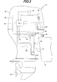
- FIG. 3 is an enlarged side view of the outboard motor.
- a symbol 10 indicates an outboard motor. As illlustrated, the outboard motor 10 is clamped (fastened) to the stem or transom of a boat (hull) 12.
- the outboard motor 10 is fastened to the boat 12 through a swivel case 14, tilting shaft 16 and stem brackets 18.
- the outboard motor 10 is equipped with a mount frame 20 and shaft 22.
- the shaft 22 is housed in the swivel case 14 to be rotatable about the vertical axis such that the outboard motor 10 can be rotated about the vertical axis relative to the boat 12.
- the mount frame 20 is fixed at its upper end and lower end to a frame (not shown) constituting a main body of the outboard motor 10.
- An electric steering motor (actuator) 24 for operating the shaft 22 and a power tilt-trim unit 26 for regulating a tilt angle and trim angle of the outboard motor 10 are installed near the swivel case 14.
- the output shaft of the steering motor 24 is connected to the upper end of the mount frame 20 via a speed reduction gear mechanism 28.
- a rotational output of the steering motor 24 is transmitted to the mount frame 20 via the speed reduction gear mechanism 28, whereby the outboard motor 10 is steered about the shaft 22 as a steering axis to the right and left directions (steered about the vertical axis).
- the power tilt-trim unit 26 integrally comprises a hydraulic cylinder 26a for adjusting the tilt angle and a hydraulic cylinder 26b for adjusting the trim angle.
- a hydraulic cylinder 26a for adjusting the tilt angle
- a hydraulic cylinder 26b for adjusting the trim angle.
- An internal combustion engine (hereinafter referred to as the "engine") 30 is disposed in the upper portion of the outboard motor 10.
- the engine 30 comprises a spark-ignition, water-cooling gasoline engine with a displacement of 2,200 cc.
- the engine 30 is located above the water surface and covered by an engine cover 32.
- An intake pipe 34 of the engine 30 is connected to a throttle body 36.
- the throttle body 36 has a throttle valve 38 installed therein and an electric throttle motor (actuator) 40 for opening and closing the throttle valve 38 is integrally disposed thereto.
- actuator electric throttle motor
- the output shaft of the throttle motor 40 is connected to the throttle valve 38 via a speed reduction gear mechanism (not shown) disposed near the throttle body 36.
- the throttle motor 40 is operated to open and close the throttle valve 38, thereby regulating the flow rate of the air sucked in the engine 30 to control the engine speed NE.
- the outboard motor 10 further comprises a drive shaft (vertical shaft) 42 installed parallel with the vertical axis to be rotatably supported, a torque converter 44 interposed between the engine 30 and drive shaft 42, a hydraulic pump 46 that is attached to the drive shaft 42 and pumps operating oil to a lubricated portion of the engine 30, the torque converter 44 and the like, and a reservoir 50 for reserving the operating oil.
- a drive shaft vertical shaft
- a torque converter 44 interposed between the engine 30 and drive shaft 42
- a hydraulic pump 46 that is attached to the drive shaft 42 and pumps operating oil to a lubricated portion of the engine 30, the torque converter 44 and the like
- a reservoir 50 for reserving the operating oil.
- the upper end of the drive shaft 42 is connected to a crankshaft 52 of the engine 30 through the torque converter 44 and the lower end thereof is connected via a shift mechanism 54 with a propeller shaft 56 supported to be rotatable about the horizontal axis.
- a propeller shaft 56 supported to be rotatable about the horizontal axis.
- One end of the propeller shaft 56 is attached with a propeller 60.
- the drive shaft 42 connects the engine 30 with the propeller 60.
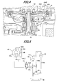
- FIG. 4 is an enlarged sectional view showing a region around the torque converter 44 shown in FIG. 2 .
- the torque converter 44 includes a pump impeller 44a connected to the crankshaft 52 through a drive plate 62, a turbine runner 44b that is installed to face the pump impeller 44a to receive/discharge the operating oil and connected to the drive shaft 42, a stator 44c installed between the pump impeller 44a and turbine runner 44b, a lockup clutch 44d and other components.
- FIG. 5 is a hydraulic circuit diagram schematically showing the torque converter 44, hydraulic pump 46, etc.
- the hydraulic pump 46 driven by the engine 30 pumps up the operating oil in the reservoir 50 and forwards it to a first oil passage 64a.
- the pressurized operating oil forwarded to the first oil passage 64a is supplied to the lubricated portion of the engine 30 or the like and then returns to the reservoir 50 through a second oil passage 64b.
- the first oil passage 64a is provided with a third oil passage 64c connecting the first oil passage 64a with an intake hole of the hydraulic pump 46.
- the third oil passage 64c is interposed with a relief valve 66 that opens when the pressure of the operating oil supplied to the engine 30 is at or above a defined value and closes when it is below the defined value.
- a fourth oil passage 64d for circulating the operating oil supplied to the torque converter 44 is connected to the first oil passage 64a at a point between a discharge hole of the hydraulic pump 46 and a branch point of the first and third oil passages 64a, 64c.
- a fifth oil passage 64e for circulating the operating oil returning from the torque converter 44 to the hydraulic pump 46 is connected to the third oil passage 64c at a location downstream of the relief valve 66.
- the fourth and fifth oil passages 64d, 64e are installed with a lockup control valve 70 for controlling the operation of the lockup clutch 44d.
- the lockup control valve 70 is a solenoid valve.
- the output of the valve 70 is connected to a piston chamber 44d1 of the lockup clutch 44d of the torque converter 44, and also connected to a chamber (rear chamber) 44d2 disposed in the rear of the piston chamber 44d1.
- the lockup control valve 70 switches the oil passage upon being magnetized/demagnetized, thereby controlling the ON/OFF state (engagement/release) of the lockup clutch 44d.
- the lockup control valve 70 when the lockup control valve 70 is magnetized, the operating oil is supplied to the piston chamber 44d1 and discharged from the rear chamber 44d2 so as to make the lockup clutch 44d ON (engaged), and when the valve 70 is demagnetized (the status in FIG. 5 ; initial condition), the operating oil is supplied to the rear chamber 44d2 and discharged from the piston chamber 44d1 so as to make the lockup clutch 44d OFF (released). Since the details of the aforementioned torque converter 44 is disclosed in '498, further explanation is omitted here.
- the shift mechanism 54 comprises a forward bevel gear 54a and reverse bevel gear 54b which are connected to the drive shaft 42 to be rotated, a clutch 54c which can engage the propeller shaft 56 with either one of the forward bevel gear 54a and reverse bevel gear 54b, and other components.
- the interior of the engine cover 32 is disposed with an electric shift motor (actuator) 72 that drives the shift mechanism 54.
- the output shaft of the shift motor 72 can be connected via a speed reduction gear mechanism (not shown) with the upper end of a shift rod 54d of the shift mechanism 54. Therefore, when the shift motor 72 is operated, its output appropriately displaces the shift rod 54d and a shift slider 54e to move the clutch 54c to one shift position from among a forward position, reverse position and neutral position.
- the outboard motor 10 is equipped with a power source (not shown) such as a battery or the like attached to the engine 30 to supply operating power to the motors 24, 40, 72, etc.
- a power source such as a battery or the like attached to the engine 30 to supply operating power to the motors 24, 40, 72, etc.
- a throttle opening sensor (throttle opening detector) 80 is installed near the throttle valve 38 and produces an output or signal indicative of opening of the throttle valve 38, i.e., throttle opening TH.
- a shift position sensor 82 installed near the shift rod 54d produces an output or signal corresponding to a shift position (neutral, forward or reverse) and a neutral switch 84 also installed near the shift rod 54d produces an ON signal when the shift position is neutral and an OFF signal when it is forward or reverse.
- a crank angle sensor (engine speed detector) 86 is installed near the crankshaft 52 of the engine 30 and produces a pulse signal at every predetermined crank angle.
- a drive shaft rotation speed sensor 90 is installed near the drive shaft 42 and produces an output or signal indicative of rotation speed of the drive shaft 42.
- the outputs of the foregoing sensors and switch are sent to an Electronic Control Unit (ECU) 94 disposed in the outboard motor 10.
- the ECU 94 has a microcomputer including a CPU, ROM, RAM and other devices and installed in the engine cover 32 of the outboard motor 10.
- a steering wheel 102 is installed near a cockpit (the operator's seat) 100 of the boat 12 to be manipulated or rotated by the operator.
- a steering angle sensor 104 installed near a shaft (not shown) of the steering wheel 102 produces an output or signal corresponding to the steering angle of the steering wheel 102.
- a remote control box 106 provided near the cockpit 100 is equipped with a shift/throttle lever 110 installed to be manipulated by the operator. Upon manipulation, the lever 110 can be swung in the front-back direction from the initial position and is used by the operator to input a shift position change command and engine speed regulation command.
- a lever position sensor 112 is installed in the remote control box 106 and produces an output or signal corresponding to a position of the lever 110. The outputs of the sensors 104, 112 are also sent to the ECU 94.
- the ECU 94 controls the operations of the motors and ON/OFF state of the lockup clutch 44d of the torque converter 44.
- FIG. 6 is a flowchart showing the control of ON/OFF state of the lockup clutch 44d.
- the illustrated program is executed by the ECU 94 at a predetermined interval, e.g., 100 milliseconds.
- the program begins in S10, in which it is determined whether the shift position is neutral. This determination is made by checking as to whether the neutral switch 84 outputs the ON signal. When the result in S10 is negative, the program proceeds to S12, in which the throttle opening TH is detected or calculated from the output of the throttle opening sensor 80 and to S 14, in which a change amount (variation) DTH of the detected throttle opening TH per a unit time (e.g., 500 milliseconds) is calculated.
- a change amount (variation) DTH of the detected throttle opening TH per a unit time e.g., 500 milliseconds
- the program proceeds to S16, in which it is determined whether the engine 30 is in a decelerating condition.
- the determination in S16 whether the engine 30 (precisely, the boat 12) is decelerating is made by checking as to whether the change amount DTH of the throttle opening TH is less than 0 degree. In other words, when the change amount DTH is a negative value, the engine 30 is determined to be decelerating and when the change amount DTH is 0 or a positive value, it is determined to be at a constant speed or accelerating.
- the program proceeds to S18, in which it is determined whether a bit of an amplification determination flag of the torque converter 44 (torque converter amplification determination flag) is 0.
- the bit of this flag is set to 1 when a condition where the output torque of the engine 30 is amplified through the torque converter 44 and transmitted to the drive shaft 42 (i.e., where the operation of the outboard motor 10 is in a range (torque amplification range) that the torque is to be amplified by the torque converter 44 to accelerate the boat 12) is established, and reset to 0 when the output torque of the engine 30 is not amplified (i.e., the operation of the outboard motor 10 is out of the torque amplification range).
- the result in S18 in the first program loop is generally affirmative and the program proceeds to S20, in which it is determined whether the engine 30 is in an accelerating condition including abrupt acceleration.
- the calculated change amount DTH of the throttle opening TH is compared with a predetermined value (threshold value) DTHref and, when the change amount DTH is equal to or greater than the predetermined value DTHref, the engine 30 is determined to be in the accelerating condition.
- the predetermined value DTHref is set to a value (e.g., 0.5 degree) enabling to determine whether the engine 30 is accelerating.
- a timer value tm is calculated by retrieving mapped values of a table (whose characteristics are shown in FIG. 7 ) using the detected engine speed NE, the calculated timer value tm is set to a timer T (down timer) and down-counting (time measurement) is started.
- the timer T is used to measure the time to hold the lockup clutch 44d to the ON state (i.e., the time until the lockup clutch 44d is made OFF) when the engine 30 is determined to be in the accelerating condition including abrupt acceleration
- the timer value tm is a value indicating a time period (predetermined time period) during which the lockup clutch 44d should be held ON.
- the timer value tm (predetermined time period) is changed depending on the engine speed NE. Specifically, when the engine speed NE is relatively low (0 to 1000 rpm), the timer value tm is set to 1.0 second and is decreased with increasing engine speed NE. Precisely, when the engine speed NE is 1000 to 2000 rpm, the timer value tm is set to 0.8 second, when the speed NE is 2000 to 3000 rpm, set to 0.6 second, and when the speed NE is equal to or greater than 3000 rpm, set to 0 second.
- time period (timer value tm) during which the lockup clutch 44d is held ON is changed or set to be relatively long at the low engine speed NE and relatively short at the high engine speed NE.
- the characteristics shown in FIG. 7 are experimentally obtained and stored in the ROM of the ECU 94 beforehand.
- the program proceeds to S26, in which the torque converter 44 is controlled in a lockup-ON mode.
- the lockup-ON mode magnetizes the lockup control valve 70 to make the lockup clutch 44d ON.
- the program proceeds to S28, in which it is determined whether a value of the timer T became 0. So far as the result in S28 is negative, the determination of S28 is repeated (i.e., the lockup-ON mode is continued) and when the result is affirmative, the program proceeds to S30, in which the torque converter 44 is controlled in a lockup-OFF mode.
- the lockup-OFF mode demagnetizes the lockup control valve 70 to make the lockup clutch 44d OFF.
- the lockup clutch 44d is held ON during the predetermined time period (timer value tm) immediately after acceleration of the engine 30 and made OFF after elapse of the predetermined time period (i.e., when the value of the timer T became 0). Owing to this configuration, the output torque of the engine 30 is amplified by the torque converter 44 and transmitted to the drive shaft 42, thereby further improving acceleration performance.
- the program proceeds to S32, in which a bit of the torque converter amplification determination flag is set to 1 and the present program loop is terminated. Since the bit of this flag is set to 1, the result in S18 in the next and subsequent loops is negative and the program proceeds to S34.
- an input rotation speed NIN and output rotation speed NOUT of the torque converter 44 are detected or calculated. Since the input rotation speed NIN is identical with the engine speed NE because the input side of the torque converter 44 is connected to the crankshaft 52 of the engine 30, it is detected by counting the output pulses of the crank angle sensor 86. The output rotation speed NOUT is detected from the output of the drive shaft rotation speed sensor 90.
- the program proceeds to S36, in which a speed ratio e of the torque converter 44 is calculated based on the input rotation speed NIN and output rotation speed NOUT.
- the speed ratio e is a value obtained by dividing the output rotation speed NOUT by the input rotation speed NIN as shown in the following equation.
- the program proceeds to S38, in which it is determined whether the torque amplification range is ended, precisely, whether the torque amplification range (acceleration range) is saturated and the acceleration is completed. Specifically, the calculated speed ratio e is compared with a torque converter reference value (threshold value) eref to determine whether the speed ratio e is equal to or greater than the reference value eref, and when the result is affirmative, it is determined that the torque amplification range is ended.
- the reference value eref is set to a value (e.g., 0.8) enabling to determine whether the torque amplification range is ended.
- a change amount DNIN of the input rotation speed NIN i.e., a change amount (variation) of the engine speed NE
- the change amount DNIN is obtained by subtracting the input rotation speed NIN detected in the present program loop from that detected in the previous program loop.
- the program proceeds to S42, in which it is determined whether the speed of the boat 12 remains stable at the maximum speed or thereabout after completing acceleration. This determination is made by comparing an absolute value of the calculated change amount DNIN with a prescribed value (threshold value) DNINref to determine whether the absolute value is equal to or less than the prescribed value DNINref, and when the result is affirmative, determining that the speed of the boat 12 is stable at the maximum value or thereabout.
- the prescribed value DNINref is set to a value (e.g., 500 rpm) enabling to determine whether the speed of the boat 12 remains stable at the maximum value or thereabout after completing acceleration, specifically, the change amount DNIN is relatively small.
- this embodiment is configured to have an apparatus for (and a method of) controlling an outboard motor (10) mounted on a stem of a boat (12) and having an internal combustion engine (30) to power a propeller (60), a drive shaft (42) that connects the engine and the propeller, and a torque converter (44) that is interposed between the engine and the drive shaft and is equipped with a lockup clutch (44d), comprising a throttle opening detector (throttle opening sensor 80, ECU 94, S12) that detects throttle opening (TH) of a throttle valve (38) of the engine, a throttle opening change amount calculator (ECU 94, S14) that calculates a change amount (DTH) of the calculated throttle opening, and a clutch ON unit (ECU 94, S20 to S28) that makes the lockup clutch ON when the calculated change amount is equal to or greater than a predetermined value (DTHref), and keeps the lockup clutch ON during a predetermined time period (tm).
- a throttle opening detector throttle opening sensor 80, ECU 94,
- the apparatus further includes an engine speed detector (crank angle sensor 86, ECU 94, S22) that detects speed (NE) of the engine, and a predetermined time period changer (ECU 94, S24) that changes the predetermined time period depending on the speed of the engine.
- the predetermined time period changer changes the predetermined time period to decrease as the speed of the engine increases (S24). With this, it becomes possible to determine the time period during which the lockup clutch 44d is kept ON in accordance with the engine speed NE more appropriately.
- the predetermined value is a value enabling to determine whether the engine is accelerating (S20). With this, it becomes possible to make and hold the lockup clutch 44d ON during a predetermined time period immediately after acceleration of the engine 30.
Landscapes
- Engineering & Computer Science (AREA)
- Mechanical Engineering (AREA)
- Chemical & Material Sciences (AREA)
- Combustion & Propulsion (AREA)
- Ocean & Marine Engineering (AREA)
- General Engineering & Computer Science (AREA)
- Control Of Fluid Gearings (AREA)
- Control Of Vehicle Engines Or Engines For Specific Uses (AREA)
- Electrical Control Of Air Or Fuel Supplied To Internal-Combustion Engine (AREA)
Abstract
Description
- This invention relates to an outboard motor control apparatus, particularly to an apparatus for controlling an outboard motor having a torque converter.
- In recent years, there is proposed an outboard motor having a torque converter interposed between an internal combustion engine and drive shaft to amplify output torque of the engine and then transmit it to the drive shaft for enhancing acceleration performance, etc., as taught, for example, by Japanese Laid-Open Patent Application No.
2007-315498 - However, in the outboard motor having the torque converter as in the reference, it disadvantageously takes time until starting to increase in the boat speed after the engine speed is accelerated. Specifically, due to slippage of the torque converter, transmittance of an engine output to the drive shaft immediately after the engine speed is accelerated is slightly delayed starting compared to the case of using an outboard motor having an engine directly connected to a drive shaft, so that it takes time until the boat speed starts increasing and there is room for improvement in acceleration performance.
- An object of this invention is therefore to overcome the foregoing drawback by providing an apparatus for controlling an outboard motor having a torque converter, which apparatus can improve acceleration performance immediately after speed of an engine is accelerated.
- In order to achieve the object, this invention provides an apparatus for controlling an outboard motor mounted on a stem of a boat and having an internal combustion engine to power a propeller, a drive shaft that connects the engine and the propeller, and a torque converter that is interposed between the engine and the drive shaft and is equipped with a lockup clutch, comprising a throttle opening detector that detects throttle opening of a throttle valve of the engine, a throttle opening change amount calculator that calculates a change amount of the calculated throttle opening, and a clutch ON unit that makes the lockup clutch ON when the calculated change amount is equal to or greater than a predetermined value, and keeps the lockup clutch ON during a predetermined time period.
- The above and other objects and advantages of the invention will be more apparent from the following description and drawings in which:
-
FIG. 1 is an overall schematic view of an outboard motor control apparatus including a boat (hull) according to an embodiment of the invention; -
FIG. 2 is a sectional side view partially showing the outboard motor shown inFIG. 1 ; -
FIG. 3 is an enlarged side view of the outboard motor shown inFIG. 1 ; -
FIG. 4 is an enlarged sectional view showing a region around a torque converter shown inFIG. 2 ; -
FIG. 5 is a hydraulic circuit diagram schematically showing the torque converter, a hydraulic pump and other components shown inFIG. 2 ; -
FIG. 6 is a flowchart showing the control of ON/OFF state of a lockup clutch of the torque converter shown inFIG. 1 , etc.; and -
FIG. 7 is a graph showing table characteristics of timer values with respect to engine speed, which are used in the process ofFIG. 6 flowchart. - A preferred embodiment of an outboard motor control apparatus according to the invention will now be explained with reference to the attached drawings.
-
FIG. 1 is an overall schematic view of an outboard motor control apparatus including a boat (hull) according to an embodiment of the invention.FIG. 2 is a sectional side view partially showing the outboard motor shown inFIG. 1 andFIG. 3 is an enlarged side view of the outboard motor. - In
FIGs. 1 to 3 , asymbol 10 indicates an outboard motor. As illlustrated, theoutboard motor 10 is clamped (fastened) to the stem or transom of a boat (hull) 12. - As shown in
FIG. 2 , theoutboard motor 10 is fastened to theboat 12 through aswivel case 14, tiltingshaft 16 andstem brackets 18. Theoutboard motor 10 is equipped with amount frame 20 andshaft 22. Theshaft 22 is housed in theswivel case 14 to be rotatable about the vertical axis such that theoutboard motor 10 can be rotated about the vertical axis relative to theboat 12. Themount frame 20 is fixed at its upper end and lower end to a frame (not shown) constituting a main body of theoutboard motor 10. - An electric steering motor (actuator) 24 for operating the
shaft 22 and a power tilt-trim unit 26 for regulating a tilt angle and trim angle of theoutboard motor 10 are installed near theswivel case 14. The output shaft of thesteering motor 24 is connected to the upper end of themount frame 20 via a speedreduction gear mechanism 28. Specifically, a rotational output of thesteering motor 24 is transmitted to themount frame 20 via the speedreduction gear mechanism 28, whereby theoutboard motor 10 is steered about theshaft 22 as a steering axis to the right and left directions (steered about the vertical axis). - The power tilt-
trim unit 26 integrally comprises ahydraulic cylinder 26a for adjusting the tilt angle and ahydraulic cylinder 26b for adjusting the trim angle. When thehydraulic cylinders swivel case 14 is rotated about thetilting shaft 16 as a rotational axis, thereby tiling up/down and trimming up/down theoutboard motor 10. - An internal combustion engine (hereinafter referred to as the "engine") 30 is disposed in the upper portion of the
outboard motor 10. Theengine 30 comprises a spark-ignition, water-cooling gasoline engine with a displacement of 2,200 cc. Theengine 30 is located above the water surface and covered by anengine cover 32. - An
intake pipe 34 of theengine 30 is connected to athrottle body 36. Thethrottle body 36 has athrottle valve 38 installed therein and an electric throttle motor (actuator) 40 for opening and closing thethrottle valve 38 is integrally disposed thereto. - The output shaft of the
throttle motor 40 is connected to thethrottle valve 38 via a speed reduction gear mechanism (not shown) disposed near thethrottle body 36. Thethrottle motor 40 is operated to open and close thethrottle valve 38, thereby regulating the flow rate of the air sucked in theengine 30 to control the engine speed NE. - The
outboard motor 10 further comprises a drive shaft (vertical shaft) 42 installed parallel with the vertical axis to be rotatably supported, atorque converter 44 interposed between theengine 30 anddrive shaft 42, ahydraulic pump 46 that is attached to thedrive shaft 42 and pumps operating oil to a lubricated portion of theengine 30, thetorque converter 44 and the like, and areservoir 50 for reserving the operating oil. - The upper end of the
drive shaft 42 is connected to acrankshaft 52 of theengine 30 through thetorque converter 44 and the lower end thereof is connected via ashift mechanism 54 with apropeller shaft 56 supported to be rotatable about the horizontal axis. One end of thepropeller shaft 56 is attached with apropeller 60. Thus thedrive shaft 42 connects theengine 30 with thepropeller 60. -
FIG. 4 is an enlarged sectional view showing a region around thetorque converter 44 shown inFIG. 2 . - As shown in
FIG. 4 , thetorque converter 44 includes apump impeller 44a connected to thecrankshaft 52 through adrive plate 62, aturbine runner 44b that is installed to face thepump impeller 44a to receive/discharge the operating oil and connected to thedrive shaft 42, astator 44c installed between thepump impeller 44a andturbine runner 44b, alockup clutch 44d and other components. -
FIG. 5 is a hydraulic circuit diagram schematically showing thetorque converter 44,hydraulic pump 46, etc. - The
hydraulic pump 46 driven by theengine 30 pumps up the operating oil in thereservoir 50 and forwards it to afirst oil passage 64a. The pressurized operating oil forwarded to thefirst oil passage 64a is supplied to the lubricated portion of theengine 30 or the like and then returns to thereservoir 50 through asecond oil passage 64b. - The
first oil passage 64a is provided with athird oil passage 64c connecting thefirst oil passage 64a with an intake hole of thehydraulic pump 46. Thethird oil passage 64c is interposed with arelief valve 66 that opens when the pressure of the operating oil supplied to theengine 30 is at or above a defined value and closes when it is below the defined value. - A
fourth oil passage 64d for circulating the operating oil supplied to thetorque converter 44 is connected to thefirst oil passage 64a at a point between a discharge hole of thehydraulic pump 46 and a branch point of the first andthird oil passages fifth oil passage 64e for circulating the operating oil returning from thetorque converter 44 to thehydraulic pump 46 is connected to thethird oil passage 64c at a location downstream of therelief valve 66. The fourth andfifth oil passages lockup control valve 70 for controlling the operation of thelockup clutch 44d. - The
lockup control valve 70 is a solenoid valve. The output of thevalve 70 is connected to a piston chamber 44d1 of thelockup clutch 44d of thetorque converter 44, and also connected to a chamber (rear chamber) 44d2 disposed in the rear of the piston chamber 44d1. Thelockup control valve 70 switches the oil passage upon being magnetized/demagnetized, thereby controlling the ON/OFF state (engagement/release) of thelockup clutch 44d. - Specifically, when the
lockup control valve 70 is magnetized, the operating oil is supplied to the piston chamber 44d1 and discharged from the rear chamber 44d2 so as to make thelockup clutch 44d ON (engaged), and when thevalve 70 is demagnetized (the status inFIG. 5 ; initial condition), the operating oil is supplied to the rear chamber 44d2 and discharged from the piston chamber 44d1 so as to make thelockup clutch 44d OFF (released). Since the details of theaforementioned torque converter 44 is disclosed in '498, further explanation is omitted here. - The explanation of
FIG. 2 will be resumed. Theshift mechanism 54 comprises aforward bevel gear 54a andreverse bevel gear 54b which are connected to thedrive shaft 42 to be rotated, aclutch 54c which can engage thepropeller shaft 56 with either one of theforward bevel gear 54a andreverse bevel gear 54b, and other components. - The interior of the
engine cover 32 is disposed with an electric shift motor (actuator) 72 that drives theshift mechanism 54. The output shaft of theshift motor 72 can be connected via a speed reduction gear mechanism (not shown) with the upper end of ashift rod 54d of theshift mechanism 54. Therefore, when theshift motor 72 is operated, its output appropriately displaces theshift rod 54d and ashift slider 54e to move theclutch 54c to one shift position from among a forward position, reverse position and neutral position. - When the shift position is forward or reverse, the rotational output of the
drive shaft 42 is transmitted via theshift mechanism 54 to thepropeller shaft 56 to rotate thepropeller 60 in one of the directions making theboat 12 move forward or rearward. Theoutboard motor 10 is equipped with a power source (not shown) such as a battery or the like attached to theengine 30 to supply operating power to themotors - As shown in
FIG. 3 , a throttle opening sensor (throttle opening detector) 80 is installed near thethrottle valve 38 and produces an output or signal indicative of opening of thethrottle valve 38, i.e., throttle opening TH. Ashift position sensor 82 installed near theshift rod 54d produces an output or signal corresponding to a shift position (neutral, forward or reverse) and aneutral switch 84 also installed near theshift rod 54d produces an ON signal when the shift position is neutral and an OFF signal when it is forward or reverse. - A crank angle sensor (engine speed detector) 86 is installed near the
crankshaft 52 of theengine 30 and produces a pulse signal at every predetermined crank angle. A drive shaftrotation speed sensor 90 is installed near thedrive shaft 42 and produces an output or signal indicative of rotation speed of thedrive shaft 42. - The outputs of the foregoing sensors and switch are sent to an Electronic Control Unit (ECU) 94 disposed in the
outboard motor 10. TheECU 94 has a microcomputer including a CPU, ROM, RAM and other devices and installed in theengine cover 32 of theoutboard motor 10. - As shown in
FIG. 1 , asteering wheel 102 is installed near a cockpit (the operator's seat) 100 of theboat 12 to be manipulated or rotated by the operator. Asteering angle sensor 104 installed near a shaft (not shown) of thesteering wheel 102 produces an output or signal corresponding to the steering angle of thesteering wheel 102. - A
remote control box 106 provided near thecockpit 100 is equipped with a shift/throttle lever 110 installed to be manipulated by the operator. Upon manipulation, thelever 110 can be swung in the front-back direction from the initial position and is used by the operator to input a shift position change command and engine speed regulation command. Alever position sensor 112 is installed in theremote control box 106 and produces an output or signal corresponding to a position of thelever 110. The outputs of thesensors ECU 94. - Based on the inputted outputs, the
ECU 94 controls the operations of the motors and ON/OFF state of the lockup clutch 44d of thetorque converter 44. -
FIG. 6 is a flowchart showing the control of ON/OFF state of the lockup clutch 44d. The illustrated program is executed by theECU 94 at a predetermined interval, e.g., 100 milliseconds. - The program begins in S10, in which it is determined whether the shift position is neutral. This determination is made by checking as to whether the
neutral switch 84 outputs the ON signal. When the result in S10 is negative, the program proceeds to S12, in which the throttle opening TH is detected or calculated from the output of thethrottle opening sensor 80 and toS 14, in which a change amount (variation) DTH of the detected throttle opening TH per a unit time (e.g., 500 milliseconds) is calculated. - The program proceeds to S16, in which it is determined whether the
engine 30 is in a decelerating condition. The determination in S16 whether the engine 30 (precisely, the boat 12) is decelerating is made by checking as to whether the change amount DTH of the throttle opening TH is less than 0 degree. In other words, when the change amount DTH is a negative value, theengine 30 is determined to be decelerating and when the change amount DTH is 0 or a positive value, it is determined to be at a constant speed or accelerating. - When the result in S16 is negative, the program proceeds to S18, in which it is determined whether a bit of an amplification determination flag of the torque converter 44 (torque converter amplification determination flag) is 0. As explained below, the bit of this flag is set to 1 when a condition where the output torque of the
engine 30 is amplified through thetorque converter 44 and transmitted to the drive shaft 42 (i.e., where the operation of theoutboard motor 10 is in a range (torque amplification range) that the torque is to be amplified by thetorque converter 44 to accelerate the boat 12) is established, and reset to 0 when the output torque of theengine 30 is not amplified (i.e., the operation of theoutboard motor 10 is out of the torque amplification range). - Since the initial value of the bit of the torque converter amplification determination flag is 0, the result in S18 in the first program loop is generally affirmative and the program proceeds to S20, in which it is determined whether the
engine 30 is in an accelerating condition including abrupt acceleration. Specifically, the calculated change amount DTH of the throttle opening TH is compared with a predetermined value (threshold value) DTHref and, when the change amount DTH is equal to or greater than the predetermined value DTHref, theengine 30 is determined to be in the accelerating condition. The predetermined value DTHref is set to a value (e.g., 0.5 degree) enabling to determine whether theengine 30 is accelerating. - When the result in S20 is negative, i.e., the
engine 30 is neither decelerating nor accelerating but theboat 12 cruises at a constant speed, the remaining steps are skipped and when the result is affirmative, the program proceeds to S22, in which the output pulse of thecrank angle sensor 86 is counted to detect or calculate the engine speed NE. - The program proceeds to S24, in which a timer value tm is calculated by retrieving mapped values of a table (whose characteristics are shown in
FIG. 7 ) using the detected engine speed NE, the calculated timer value tm is set to a timer T (down timer) and down-counting (time measurement) is started. As described below, the timer T is used to measure the time to hold the lockup clutch 44d to the ON state (i.e., the time until the lockup clutch 44d is made OFF) when theengine 30 is determined to be in the accelerating condition including abrupt acceleration, and the timer value tm is a value indicating a time period (predetermined time period) during which the lockup clutch 44d should be held ON. - As shown in
FIG. 7 , the timer value tm (predetermined time period) is changed depending on the engine speed NE. Specifically, when the engine speed NE is relatively low (0 to 1000 rpm), the timer value tm is set to 1.0 second and is decreased with increasing engine speed NE. Precisely, when the engine speed NE is 1000 to 2000 rpm, the timer value tm is set to 0.8 second, when the speed NE is 2000 to 3000 rpm, set to 0.6 second, and when the speed NE is equal to or greater than 3000 rpm, set to 0 second. - In other words, the time period (timer value tm) during which the lockup clutch 44d is held ON is changed or set to be relatively long at the low engine speed NE and relatively short at the high engine speed NE. The characteristics shown in
FIG. 7 are experimentally obtained and stored in the ROM of theECU 94 beforehand. - The program proceeds to S26, in which the
torque converter 44 is controlled in a lockup-ON mode. The lockup-ON mode magnetizes thelockup control valve 70 to make the lockup clutch 44d ON. As a result, since thecrankshaft 52 of theengine 30 and thedrive shaft 42 are directly connected, slippage or the like of thetorque converter 44 can be prevented and the speed of theboat 12 promptly starts increasing, thereby improving acceleration performance immediately after theengine 30 is accelerated. - Next, the program proceeds to S28, in which it is determined whether a value of the timer T became 0. So far as the result in S28 is negative, the determination of S28 is repeated (i.e., the lockup-ON mode is continued) and when the result is affirmative, the program proceeds to S30, in which the
torque converter 44 is controlled in a lockup-OFF mode. The lockup-OFF mode demagnetizes thelockup control valve 70 to make the lockup clutch 44d OFF. - Thus, the lockup clutch 44d is held ON during the predetermined time period (timer value tm) immediately after acceleration of the
engine 30 and made OFF after elapse of the predetermined time period (i.e., when the value of the timer T became 0). Owing to this configuration, the output torque of theengine 30 is amplified by thetorque converter 44 and transmitted to thedrive shaft 42, thereby further improving acceleration performance. - The program proceeds to S32, in which a bit of the torque converter amplification determination flag is set to 1 and the present program loop is terminated. Since the bit of this flag is set to 1, the result in S18 in the next and subsequent loops is negative and the program proceeds to S34.
- In S34, an input rotation speed NIN and output rotation speed NOUT of the
torque converter 44 are detected or calculated. Since the input rotation speed NIN is identical with the engine speed NE because the input side of thetorque converter 44 is connected to thecrankshaft 52 of theengine 30, it is detected by counting the output pulses of thecrank angle sensor 86. The output rotation speed NOUT is detected from the output of the drive shaftrotation speed sensor 90. - The program proceeds to S36, in which a speed ratio e of the
torque converter 44 is calculated based on the input rotation speed NIN and output rotation speed NOUT. The speed ratio e is a value obtained by dividing the output rotation speed NOUT by the input rotation speed NIN as shown in the following equation.
- The program proceeds to S38, in which it is determined whether the torque amplification range is ended, precisely, whether the torque amplification range (acceleration range) is saturated and the acceleration is completed. Specifically, the calculated speed ratio e is compared with a torque converter reference value (threshold value) eref to determine whether the speed ratio e is equal to or greater than the reference value eref, and when the result is affirmative, it is determined that the torque amplification range is ended. The reference value eref is set to a value (e.g., 0.8) enabling to determine whether the torque amplification range is ended.
- When the result in S38 is affirmative, the program proceeds to S40, in which a change amount DNIN of the input rotation speed NIN (i.e., a change amount (variation) of the engine speed NE) is calculated. The change amount DNIN is obtained by subtracting the input rotation speed NIN detected in the present program loop from that detected in the previous program loop.
- The program proceeds to S42, in which it is determined whether the speed of the
boat 12 remains stable at the maximum speed or thereabout after completing acceleration. This determination is made by comparing an absolute value of the calculated change amount DNIN with a prescribed value (threshold value) DNINref to determine whether the absolute value is equal to or less than the prescribed value DNINref, and when the result is affirmative, determining that the speed of theboat 12 is stable at the maximum value or thereabout. The prescribed value DNINref is set to a value (e.g., 500 rpm) enabling to determine whether the speed of theboat 12 remains stable at the maximum value or thereabout after completing acceleration, specifically, the change amount DNIN is relatively small. - When the result in S42 is affirmative, the program proceeds to S44, in which the
torque converter 44 is controlled in the lockup-ON mode, i.e., the lockup clutch 44d is made ON. As a result, since thecrankshaft 52 of theengine 30 and thedrive shaft 42 is directly connected, slippage or the like of thetorque converter 44 can be prevented and the speed of theboat 12 reaches the maximum speed (in a range of the engine performance), thereby improving acceleration performance. - After the process of S44, the program proceeds to S46, in which the bit of the torque converter amplification determination flag is reset to 0.
- When the result in S38 or S42 is negative, since it means that the torque amplification range is not ended or saturated, or the speed of the
boat 12 does not become stable at the maximum speed or thereabout, the process of S44, S46, etc., is skipped and the program is terminated. - When the result in
S 10 is affirmative, i.e., the shift position is neutral, the program proceeds to S48, in witch thetorque converter 44 is controlled in the lockup-ON mode, i.e., the lockup clutch 44d is made ON, and to S50, in which the bit of the torque converter amplification determination flag is reset to 0. - When the result in S16 is affirmative, i.e., the
engine 30 is in the decelerating condition, the program proceeds to S52, in which thetorque converter 44 is controlled in the lockup-OFF mode, i.e., the lockup clutch 44d is made OFF, and to S54, in which the bit of the torque converter amplification determination flag is reset to 0 and the program is terminated. - As stated above, this embodiment is configured to have an apparatus for (and a method of) controlling an outboard motor (10) mounted on a stem of a boat (12) and having an internal combustion engine (30) to power a propeller (60), a drive shaft (42) that connects the engine and the propeller, and a torque converter (44) that is interposed between the engine and the drive shaft and is equipped with a lockup clutch (44d), comprising a throttle opening detector (throttle opening
sensor 80,ECU 94, S12) that detects throttle opening (TH) of a throttle valve (38) of the engine, a throttle opening change amount calculator (ECU 94, S14) that calculates a change amount (DTH) of the calculated throttle opening, and a clutch ON unit (ECU 94, S20 to S28) that makes the lockup clutch ON when the calculated change amount is equal to or greater than a predetermined value (DTHref), and keeps the lockup clutch ON during a predetermined time period (tm). - With this, it becomes possible to make and hold the lockup clutch 44d ON during a predetermined time period immediately after acceleration of the
engine 30, so that the output of theengine 30 is directly transmitted to thedrive shaft 42 to enhance grip of thepropeller 60. Accordingly, the speed of the boat 12 (boat speed) promptly starts increasing, thereby improving acceleration performance immediately after speed of theengine 30 is accelerated. - The apparatus further includes an engine speed detector (crank
angle sensor 86,ECU 94, S22) that detects speed (NE) of the engine, and a predetermined time period changer (ECU 94, S24) that changes the predetermined time period depending on the speed of the engine. With this, it becomes possible to appropriately determine the time period during which the lockup clutch 44d is kept ON in accordance with the engine speed NE, thereby further improving acceleration performance immediately after speed of theengine 30 is accelerated. - In the apparatus, the predetermined time period changer changes the predetermined time period to decrease as the speed of the engine increases (S24). With this, it becomes possible to determine the time period during which the lockup clutch 44d is kept ON in accordance with the engine speed NE more appropriately.
- In the apparatus, the predetermined value is a value enabling to determine whether the engine is accelerating (S20). With this, it becomes possible to make and hold the lockup clutch 44d ON during a predetermined time period immediately after acceleration of the
engine 30. - It should be noted that, although the predetermined value DTHref, prescribed value DNINref, displacement of the
engine 30 and other values are indicated with specific values in the foregoing, they are only examples and not limited thereto.
Claims (8)
- An apparatus for controlling an outboard motor (10) mounted on a stem of a boat (12) and having an internal combustion engine (30) to power a propeller (60), a drive shaft (42) that connects the engine and the propeller, and a torque converter (44) that is interposed between the engine and the drive shaft and is equipped with a lockup clutch (44d),
characterized by:a throttle opening detector (80, 94, S 12) that detects throttle opening (TH) of a throttle valve (38) of the engine;a throttle opening change amount calculator (94, S14) that calculates a change amount (DTH) of the calculated throttle opening; anda clutch ON unit (94, S20 to S28) that makes the lockup clutch ON when the calculated change amount is equal to or greater than a predetermined value (DTHref), and keeps the lockup clutch ON during a predetermined time period (tm). - The apparatus according to claim 1, further including:an engine speed detector (86, 94, S22) that detects speed (NE) of the engine; anda predetermined time period changer (ECU 94, S24) that changes the predetermined time period depending on the speed of the engine.
- The apparatus according to claim 2, wherein the predetermined time period changer changes the predetermined time period to decrease as the speed of the engine increases (S24).
- The apparatus according to any of claims 1 to 3, wherein the predetermined value is a value enabling to determine whether the engine is accelerating (S20).
- A method of controlling an outboard motor (10) mounted on a stem of a boat (12) and having an internal combustion engine (30) to power a propeller (60), a drive shaft (42) that connects the engine and the propeller, and a torque converter (44) that is interposed between the engine and the drive shaft and is equipped with a lockup clutch (44d),
characterized by steps of:detecting throttle opening (TH) of a throttle valve (38) of the engine (S12);calculating a change amount (DTH) of the calculated throttle opening (S 14); andmaking the lockup clutch ON when the calculated change amount is equal to or greater than a predetermined value (DTHref), and keeping the lockup clutch ON during a predetermined time period (tm) (S20 to S28). - The method according to claim 5, further including steps of:detecting speed (NE) of the engine (S22); andchanging the predetermined time period depending on the speed of the engine (S24).
- The method according to claim 6, wherein the step of changing changes the predetermined time period to decrease as the speed of the engine increases (S24).
- The method according to claim 5 to 7, wherein the predetermined value is a value enabling to determine whether the engine is accelerating (S20).
Applications Claiming Priority (1)
| Application Number | Priority Date | Filing Date | Title |
|---|---|---|---|
| JP2008270213A JP4977109B2 (en) | 2008-10-20 | 2008-10-20 | Outboard motor control device |
Publications (2)
| Publication Number | Publication Date |
|---|---|
| EP2177430A1 true EP2177430A1 (en) | 2010-04-21 |
| EP2177430B1 EP2177430B1 (en) | 2011-10-12 |
Family
ID=41528636
Family Applications (1)
| Application Number | Title | Priority Date | Filing Date |
|---|---|---|---|
| EP09173204A Not-in-force EP2177430B1 (en) | 2008-10-20 | 2009-10-15 | Outboard motor control apparatus |
Country Status (5)
| Country | Link |
|---|---|
| US (1) | US8366500B2 (en) |
| EP (1) | EP2177430B1 (en) |
| JP (1) | JP4977109B2 (en) |
| AT (1) | ATE528206T1 (en) |
| CA (1) | CA2683233C (en) |
Families Citing this family (1)
| Publication number | Priority date | Publication date | Assignee | Title |
|---|---|---|---|---|
| JP7095646B2 (en) * | 2019-04-03 | 2022-07-05 | トヨタ自動車株式会社 | Vehicle control unit |
Citations (4)
| Publication number | Priority date | Publication date | Assignee | Title |
|---|---|---|---|---|
| US4558769A (en) * | 1982-12-23 | 1985-12-17 | Brunswick Corp. | Marine drive having speed controlled lock-up torque converter |
| US4887984A (en) * | 1987-09-15 | 1989-12-19 | Brunswick Corporation | Marine transmission with fluid coupler |
| EP1860347A2 (en) * | 2006-05-25 | 2007-11-28 | Yutaka Giken Co., Ltd. | Outboard engine system |
| JP2007315498A (en) | 2006-05-25 | 2007-12-06 | Yutaka Giken Co Ltd | Outboard motor |
Family Cites Families (22)
| Publication number | Priority date | Publication date | Assignee | Title |
|---|---|---|---|---|
| JPH03172667A (en) | 1989-11-30 | 1991-07-26 | Fuji Heavy Ind Ltd | Control device for continuously variable transmission |
| WO1991016235A2 (en) * | 1990-04-14 | 1991-10-31 | Zahnradfabrik Friedrichshafen Ag | Control system for operating a ship's motive installation |
| US5199326A (en) * | 1990-11-28 | 1993-04-06 | Toyota Jidosha Kabushiki Kaisha | Idle up of engine of automobile according to elevation of transmission oil temperature |
| JP3318945B2 (en) * | 1992-03-02 | 2002-08-26 | 株式会社日立製作所 | Vehicle control device, vehicle control system and vehicle control method |
| JPH08200493A (en) * | 1995-01-23 | 1996-08-06 | Nippon Soken Inc | Automatic transmission |
| JP4208108B2 (en) * | 1999-10-14 | 2009-01-14 | ヤマハマリン株式会社 | Fuel injection type 4-cycle engine |
| JP2001263062A (en) * | 2000-03-16 | 2001-09-26 | Sanshin Ind Co Ltd | Cooling structure of outboard motor |
| US6884133B2 (en) * | 2000-06-12 | 2005-04-26 | Yamaha Marine Kabushiki Kaisha | Catalyzer arrangement for outboard motor |
| JP4035334B2 (en) * | 2001-02-15 | 2008-01-23 | ヤマハ発動機株式会社 | Engine output control device for water jet propulsion boat |
| JP4002991B2 (en) * | 2001-05-17 | 2007-11-07 | トヨタ自動車株式会社 | Control device for continuously variable transmission for hybrid vehicle |
| US6481390B1 (en) * | 2001-06-19 | 2002-11-19 | Borg Warner, Inc. | Water pump with electronically controlled viscous coupling drive |
| US6695743B2 (en) * | 2001-09-13 | 2004-02-24 | Toyota Jidosha Kabushiki Kaisha | Vehicular lockup clutch-equipped transmission control apparatus and control method thereof |
| US6644933B2 (en) * | 2002-01-02 | 2003-11-11 | Borgwarner, Inc. | Water pump with electronically controlled viscous coupling drive |
| JP2004068704A (en) * | 2002-08-06 | 2004-03-04 | Suzuki Motor Corp | Outboard motor |
| JP4159918B2 (en) * | 2003-04-16 | 2008-10-01 | 本田技研工業株式会社 | Fuel cut control device for compression ignition type internal combustion engine |
| US6899575B1 (en) * | 2003-11-19 | 2005-05-31 | Brunswick Corporation | Jet drive marine propulsion system with a water pump |
| JP2005308071A (en) * | 2004-04-20 | 2005-11-04 | Aisin Seiki Co Ltd | Control device for lock-up clutch |
| US7214164B2 (en) * | 2004-12-22 | 2007-05-08 | Suzuki Motor Corporation | Shift operation control system |
| JPWO2007007707A1 (en) * | 2005-07-14 | 2009-01-29 | ヤマハマリン株式会社 | Outboard motor |
| JP4757098B2 (en) * | 2006-05-25 | 2011-08-24 | 本田技研工業株式会社 | Outboard motor |
| JP4757096B2 (en) * | 2006-05-25 | 2011-08-24 | 本田技研工業株式会社 | Outboard motor |
| JP2007314084A (en) * | 2006-05-26 | 2007-12-06 | Yamaha Marine Co Ltd | Operation control device of hydroplane |
-
2008
- 2008-10-20 JP JP2008270213A patent/JP4977109B2/en not_active Expired - Fee Related
-
2009
- 2009-10-15 EP EP09173204A patent/EP2177430B1/en not_active Not-in-force
- 2009-10-15 AT AT09173204T patent/ATE528206T1/en not_active IP Right Cessation
- 2009-10-16 US US12/580,650 patent/US8366500B2/en not_active Expired - Fee Related
- 2009-10-16 CA CA2683233A patent/CA2683233C/en not_active Expired - Fee Related
Patent Citations (4)
| Publication number | Priority date | Publication date | Assignee | Title |
|---|---|---|---|---|
| US4558769A (en) * | 1982-12-23 | 1985-12-17 | Brunswick Corp. | Marine drive having speed controlled lock-up torque converter |
| US4887984A (en) * | 1987-09-15 | 1989-12-19 | Brunswick Corporation | Marine transmission with fluid coupler |
| EP1860347A2 (en) * | 2006-05-25 | 2007-11-28 | Yutaka Giken Co., Ltd. | Outboard engine system |
| JP2007315498A (en) | 2006-05-25 | 2007-12-06 | Yutaka Giken Co Ltd | Outboard motor |
Also Published As
| Publication number | Publication date |
|---|---|
| ATE528206T1 (en) | 2011-10-15 |
| JP2010095230A (en) | 2010-04-30 |
| EP2177430B1 (en) | 2011-10-12 |
| US20100099309A1 (en) | 2010-04-22 |
| JP4977109B2 (en) | 2012-07-18 |
| US8366500B2 (en) | 2013-02-05 |
| CA2683233A1 (en) | 2010-04-20 |
| CA2683233C (en) | 2012-05-22 |
Similar Documents
| Publication | Publication Date | Title |
|---|---|---|
| EP2241500B1 (en) | Outboard motor trim control apparatus | |
| CA2683229C (en) | Outboard motor control apparatus | |
| EP2177430B1 (en) | Outboard motor control apparatus | |
| US8303360B2 (en) | Outboard motor control apparatus | |
| EP2187014B1 (en) | Outboard motor control apparatus | |
| US8118626B2 (en) | Outboard motor control apparatus | |
| CA2683172C (en) | Outboard motor control apparatus | |
| JP5162520B2 (en) | Outboard motor control device | |
| JP4977108B2 (en) | Outboard motor control device | |
| JP5107860B2 (en) | Outboard motor control device | |
| JP5232066B2 (en) | Outboard motor control device | |
| JP2010096343A (en) | Control device of outboard motor | |
| JP5193119B2 (en) | Outboard motor control device | |
| JP2010247753A (en) | Outboard motor control device | |
| JP2011038471A (en) | Control device of outboard motor |
Legal Events
| Date | Code | Title | Description |
|---|---|---|---|
| PUAI | Public reference made under article 153(3) epc to a published international application that has entered the european phase |
Free format text: ORIGINAL CODE: 0009012 |
|
| 17P | Request for examination filed |
Effective date: 20091109 |
|
| AK | Designated contracting states |
Kind code of ref document: A1 Designated state(s): AT BE BG CH CY CZ DE DK EE ES FI FR GB GR HR HU IE IS IT LI LT LU LV MC MK MT NL NO PL PT RO SE SI SK SM TR |
|
| AX | Request for extension of the european patent |
Extension state: AL BA RS |
|
| GRAP | Despatch of communication of intention to grant a patent |
Free format text: ORIGINAL CODE: EPIDOSNIGR1 |
|
| RIC1 | Information provided on ipc code assigned before grant |
Ipc: B63H 23/30 20060101AFI20110412BHEP Ipc: F16H 45/02 20060101ALI20110412BHEP Ipc: F16H 61/14 20060101ALI20110412BHEP Ipc: B63H 23/04 20060101ALI20110412BHEP |
|
| GRAS | Grant fee paid |
Free format text: ORIGINAL CODE: EPIDOSNIGR3 |
|
| GRAA | (expected) grant |
Free format text: ORIGINAL CODE: 0009210 |
|
| AK | Designated contracting states |
Kind code of ref document: B1 Designated state(s): AT BE BG CH CY CZ DE DK EE ES FI FR GB GR HR HU IE IS IT LI LT LU LV MC MK MT NL NO PL PT RO SE SI SK SM TR |
|
| REG | Reference to a national code |
Ref country code: GB Ref legal event code: FG4D |
|
| REG | Reference to a national code |
Ref country code: CH Ref legal event code: EP |
|
| REG | Reference to a national code |
Ref country code: IE Ref legal event code: FG4D |
|
| REG | Reference to a national code |
Ref country code: DE Ref legal event code: R096 Ref document number: 602009003020 Country of ref document: DE Effective date: 20120105 |
|
| REG | Reference to a national code |
Ref country code: NL Ref legal event code: VDEP Effective date: 20111012 |
|
| LTIE | Lt: invalidation of european patent or patent extension |
Effective date: 20111012 |
|
| REG | Reference to a national code |
Ref country code: AT Ref legal event code: MK05 Ref document number: 528206 Country of ref document: AT Kind code of ref document: T Effective date: 20111012 |
|
| PG25 | Lapsed in a contracting state [announced via postgrant information from national office to epo] |
Ref country code: NO Free format text: LAPSE BECAUSE OF FAILURE TO SUBMIT A TRANSLATION OF THE DESCRIPTION OR TO PAY THE FEE WITHIN THE PRESCRIBED TIME-LIMIT Effective date: 20120112 Ref country code: LT Free format text: LAPSE BECAUSE OF FAILURE TO SUBMIT A TRANSLATION OF THE DESCRIPTION OR TO PAY THE FEE WITHIN THE PRESCRIBED TIME-LIMIT Effective date: 20111012 Ref country code: IS Free format text: LAPSE BECAUSE OF FAILURE TO SUBMIT A TRANSLATION OF THE DESCRIPTION OR TO PAY THE FEE WITHIN THE PRESCRIBED TIME-LIMIT Effective date: 20120212 Ref country code: BE Free format text: LAPSE BECAUSE OF FAILURE TO SUBMIT A TRANSLATION OF THE DESCRIPTION OR TO PAY THE FEE WITHIN THE PRESCRIBED TIME-LIMIT Effective date: 20111012 |
|
| PG25 | Lapsed in a contracting state [announced via postgrant information from national office to epo] |
Ref country code: PT Free format text: LAPSE BECAUSE OF FAILURE TO SUBMIT A TRANSLATION OF THE DESCRIPTION OR TO PAY THE FEE WITHIN THE PRESCRIBED TIME-LIMIT Effective date: 20120213 Ref country code: LV Free format text: LAPSE BECAUSE OF FAILURE TO SUBMIT A TRANSLATION OF THE DESCRIPTION OR TO PAY THE FEE WITHIN THE PRESCRIBED TIME-LIMIT Effective date: 20111012 Ref country code: SE Free format text: LAPSE BECAUSE OF FAILURE TO SUBMIT A TRANSLATION OF THE DESCRIPTION OR TO PAY THE FEE WITHIN THE PRESCRIBED TIME-LIMIT Effective date: 20111012 Ref country code: MC Free format text: LAPSE BECAUSE OF NON-PAYMENT OF DUE FEES Effective date: 20111031 Ref country code: NL Free format text: LAPSE BECAUSE OF FAILURE TO SUBMIT A TRANSLATION OF THE DESCRIPTION OR TO PAY THE FEE WITHIN THE PRESCRIBED TIME-LIMIT Effective date: 20111012 Ref country code: GR Free format text: LAPSE BECAUSE OF FAILURE TO SUBMIT A TRANSLATION OF THE DESCRIPTION OR TO PAY THE FEE WITHIN THE PRESCRIBED TIME-LIMIT Effective date: 20120113 Ref country code: HR Free format text: LAPSE BECAUSE OF FAILURE TO SUBMIT A TRANSLATION OF THE DESCRIPTION OR TO PAY THE FEE WITHIN THE PRESCRIBED TIME-LIMIT Effective date: 20111012 Ref country code: SI Free format text: LAPSE BECAUSE OF FAILURE TO SUBMIT A TRANSLATION OF THE DESCRIPTION OR TO PAY THE FEE WITHIN THE PRESCRIBED TIME-LIMIT Effective date: 20111012 |
|
| PG25 | Lapsed in a contracting state [announced via postgrant information from national office to epo] |
Ref country code: CY Free format text: LAPSE BECAUSE OF FAILURE TO SUBMIT A TRANSLATION OF THE DESCRIPTION OR TO PAY THE FEE WITHIN THE PRESCRIBED TIME-LIMIT Effective date: 20111012 |
|
| PG25 | Lapsed in a contracting state [announced via postgrant information from national office to epo] |
Ref country code: SK Free format text: LAPSE BECAUSE OF FAILURE TO SUBMIT A TRANSLATION OF THE DESCRIPTION OR TO PAY THE FEE WITHIN THE PRESCRIBED TIME-LIMIT Effective date: 20111012 Ref country code: CZ Free format text: LAPSE BECAUSE OF FAILURE TO SUBMIT A TRANSLATION OF THE DESCRIPTION OR TO PAY THE FEE WITHIN THE PRESCRIBED TIME-LIMIT Effective date: 20111012 Ref country code: BG Free format text: LAPSE BECAUSE OF FAILURE TO SUBMIT A TRANSLATION OF THE DESCRIPTION OR TO PAY THE FEE WITHIN THE PRESCRIBED TIME-LIMIT Effective date: 20120112 Ref country code: EE Free format text: LAPSE BECAUSE OF FAILURE TO SUBMIT A TRANSLATION OF THE DESCRIPTION OR TO PAY THE FEE WITHIN THE PRESCRIBED TIME-LIMIT Effective date: 20111012 Ref country code: DK Free format text: LAPSE BECAUSE OF FAILURE TO SUBMIT A TRANSLATION OF THE DESCRIPTION OR TO PAY THE FEE WITHIN THE PRESCRIBED TIME-LIMIT Effective date: 20111012 |
|
| REG | Reference to a national code |
Ref country code: IE Ref legal event code: MM4A |
|
| PLBE | No opposition filed within time limit |
Free format text: ORIGINAL CODE: 0009261 |
|
| STAA | Information on the status of an ep patent application or granted ep patent |
Free format text: STATUS: NO OPPOSITION FILED WITHIN TIME LIMIT |
|
| PG25 | Lapsed in a contracting state [announced via postgrant information from national office to epo] |
Ref country code: RO Free format text: LAPSE BECAUSE OF FAILURE TO SUBMIT A TRANSLATION OF THE DESCRIPTION OR TO PAY THE FEE WITHIN THE PRESCRIBED TIME-LIMIT Effective date: 20111012 Ref country code: PL Free format text: LAPSE BECAUSE OF FAILURE TO SUBMIT A TRANSLATION OF THE DESCRIPTION OR TO PAY THE FEE WITHIN THE PRESCRIBED TIME-LIMIT Effective date: 20111012 |
|
| 26N | No opposition filed |
Effective date: 20120713 |
|
| PG25 | Lapsed in a contracting state [announced via postgrant information from national office to epo] |
Ref country code: IE Free format text: LAPSE BECAUSE OF NON-PAYMENT OF DUE FEES Effective date: 20111015 |
|
| REG | Reference to a national code |
Ref country code: DE Ref legal event code: R097 Ref document number: 602009003020 Country of ref document: DE Effective date: 20120713 |
|
| PG25 | Lapsed in a contracting state [announced via postgrant information from national office to epo] |
Ref country code: AT Free format text: LAPSE BECAUSE OF FAILURE TO SUBMIT A TRANSLATION OF THE DESCRIPTION OR TO PAY THE FEE WITHIN THE PRESCRIBED TIME-LIMIT Effective date: 20111012 |
|
| PG25 | Lapsed in a contracting state [announced via postgrant information from national office to epo] |
Ref country code: MK Free format text: LAPSE BECAUSE OF FAILURE TO SUBMIT A TRANSLATION OF THE DESCRIPTION OR TO PAY THE FEE WITHIN THE PRESCRIBED TIME-LIMIT Effective date: 20111012 Ref country code: MT Free format text: LAPSE BECAUSE OF FAILURE TO SUBMIT A TRANSLATION OF THE DESCRIPTION OR TO PAY THE FEE WITHIN THE PRESCRIBED TIME-LIMIT Effective date: 20111012 |
|
| PG25 | Lapsed in a contracting state [announced via postgrant information from national office to epo] |
Ref country code: SM Free format text: LAPSE BECAUSE OF FAILURE TO SUBMIT A TRANSLATION OF THE DESCRIPTION OR TO PAY THE FEE WITHIN THE PRESCRIBED TIME-LIMIT Effective date: 20111012 Ref country code: ES Free format text: LAPSE BECAUSE OF FAILURE TO SUBMIT A TRANSLATION OF THE DESCRIPTION OR TO PAY THE FEE WITHIN THE PRESCRIBED TIME-LIMIT Effective date: 20120123 |
|
| PG25 | Lapsed in a contracting state [announced via postgrant information from national office to epo] |
Ref country code: LU Free format text: LAPSE BECAUSE OF NON-PAYMENT OF DUE FEES Effective date: 20111015 |
|
| PG25 | Lapsed in a contracting state [announced via postgrant information from national office to epo] |
Ref country code: FI Free format text: LAPSE BECAUSE OF FAILURE TO SUBMIT A TRANSLATION OF THE DESCRIPTION OR TO PAY THE FEE WITHIN THE PRESCRIBED TIME-LIMIT Effective date: 20111012 |
|
| PG25 | Lapsed in a contracting state [announced via postgrant information from national office to epo] |
Ref country code: TR Free format text: LAPSE BECAUSE OF FAILURE TO SUBMIT A TRANSLATION OF THE DESCRIPTION OR TO PAY THE FEE WITHIN THE PRESCRIBED TIME-LIMIT Effective date: 20111012 |
|
| PG25 | Lapsed in a contracting state [announced via postgrant information from national office to epo] |
Ref country code: HU Free format text: LAPSE BECAUSE OF FAILURE TO SUBMIT A TRANSLATION OF THE DESCRIPTION OR TO PAY THE FEE WITHIN THE PRESCRIBED TIME-LIMIT Effective date: 20111012 |
|
| REG | Reference to a national code |
Ref country code: CH Ref legal event code: PL |
|
| PG25 | Lapsed in a contracting state [announced via postgrant information from national office to epo] |
Ref country code: CH Free format text: LAPSE BECAUSE OF NON-PAYMENT OF DUE FEES Effective date: 20131031 Ref country code: LI Free format text: LAPSE BECAUSE OF NON-PAYMENT OF DUE FEES Effective date: 20131031 |
|
| REG | Reference to a national code |
Ref country code: FR Ref legal event code: PLFP Year of fee payment: 8 |
|
| REG | Reference to a national code |
Ref country code: FR Ref legal event code: PLFP Year of fee payment: 9 |
|
| REG | Reference to a national code |
Ref country code: FR Ref legal event code: PLFP Year of fee payment: 10 |
|
| REG | Reference to a national code |
Ref country code: DE Ref legal event code: R084 Ref document number: 602009003020 Country of ref document: DE |
|
| REG | Reference to a national code |
Ref country code: GB Ref legal event code: 746 Effective date: 20191218 |
|
| REG | Reference to a national code |
Ref country code: DE Ref legal event code: R082 Ref document number: 602009003020 Country of ref document: DE Representative=s name: HL KEMPNER PATENTANWAELTE, SOLICITORS (ENGLAND, DE Ref country code: DE Ref legal event code: R082 Ref document number: 602009003020 Country of ref document: DE Representative=s name: HL KEMPNER PATENTANWALT, RECHTSANWALT, SOLICIT, DE Ref country code: DE Ref legal event code: R082 Ref document number: 602009003020 Country of ref document: DE Representative=s name: HL KEMPNER PARTG MBB, DE |
|
| PGFP | Annual fee paid to national office [announced via postgrant information from national office to epo] |
Ref country code: IT Payment date: 20210910 Year of fee payment: 13 |
|
| PGFP | Annual fee paid to national office [announced via postgrant information from national office to epo] |
Ref country code: GB Payment date: 20210907 Year of fee payment: 13 |
|
| GBPC | Gb: european patent ceased through non-payment of renewal fee |
Effective date: 20221015 |
|
| PG25 | Lapsed in a contracting state [announced via postgrant information from national office to epo] |
Ref country code: IT Free format text: LAPSE BECAUSE OF NON-PAYMENT OF DUE FEES Effective date: 20221015 Ref country code: GB Free format text: LAPSE BECAUSE OF NON-PAYMENT OF DUE FEES Effective date: 20221015 |
|
| PGFP | Annual fee paid to national office [announced via postgrant information from national office to epo] |
Ref country code: FR Payment date: 20230911 Year of fee payment: 15 |
|
| PGFP | Annual fee paid to national office [announced via postgrant information from national office to epo] |
Ref country code: DE Payment date: 20230830 Year of fee payment: 15 |
|
| REG | Reference to a national code |
Ref country code: DE Ref legal event code: R119 Ref document number: 602009003020 Country of ref document: DE |
|
| PG25 | Lapsed in a contracting state [announced via postgrant information from national office to epo] |
Ref country code: DE Free format text: LAPSE BECAUSE OF NON-PAYMENT OF DUE FEES Effective date: 20250501 |
|
| PG25 | Lapsed in a contracting state [announced via postgrant information from national office to epo] |
Ref country code: FR Free format text: LAPSE BECAUSE OF NON-PAYMENT OF DUE FEES Effective date: 20241031 |