EP2177380A2 - Wheel based sensor assembly - Google Patents
Wheel based sensor assembly Download PDFInfo
- Publication number
- EP2177380A2 EP2177380A2 EP09171572A EP09171572A EP2177380A2 EP 2177380 A2 EP2177380 A2 EP 2177380A2 EP 09171572 A EP09171572 A EP 09171572A EP 09171572 A EP09171572 A EP 09171572A EP 2177380 A2 EP2177380 A2 EP 2177380A2
- Authority
- EP
- European Patent Office
- Prior art keywords
- assembly
- wheel
- bracket
- sensor
- tire
- Prior art date
- Legal status (The legal status is an assumption and is not a legal conclusion. Google has not performed a legal analysis and makes no representation as to the accuracy of the status listed.)
- Withdrawn
Links
- 238000009429 electrical wiring Methods 0.000 claims description 5
- 230000037361 pathway Effects 0.000 claims description 2
- 238000003384 imaging method Methods 0.000 claims 1
- 238000005259 measurement Methods 0.000 description 7
- 230000008878 coupling Effects 0.000 description 5
- 238000010168 coupling process Methods 0.000 description 5
- 238000005859 coupling reaction Methods 0.000 description 5
- 238000012360 testing method Methods 0.000 description 5
- 230000005540 biological transmission Effects 0.000 description 4
- 238000011156 evaluation Methods 0.000 description 4
- 238000004364 calculation method Methods 0.000 description 2
- 238000010276 construction Methods 0.000 description 2
- 230000000694 effects Effects 0.000 description 2
- 238000010998 test method Methods 0.000 description 2
- 229910000831 Steel Inorganic materials 0.000 description 1
- 238000006243 chemical reaction Methods 0.000 description 1
- 239000013065 commercial product Substances 0.000 description 1
- 238000004891 communication Methods 0.000 description 1
- 238000013480 data collection Methods 0.000 description 1
- 238000013500 data storage Methods 0.000 description 1
- 230000001419 dependent effect Effects 0.000 description 1
- 230000002452 interceptive effect Effects 0.000 description 1
- 239000000463 material Substances 0.000 description 1
- 239000010959 steel Substances 0.000 description 1
- 238000012956 testing procedure Methods 0.000 description 1
Images


Classifications
-
- G—PHYSICS
- G01—MEASURING; TESTING
- G01M—TESTING STATIC OR DYNAMIC BALANCE OF MACHINES OR STRUCTURES; TESTING OF STRUCTURES OR APPARATUS, NOT OTHERWISE PROVIDED FOR
- G01M17/00—Testing of vehicles
- G01M17/007—Wheeled or endless-tracked vehicles
- G01M17/02—Tyres
Definitions
- the invention relates generally to a sensor assembly for measuring tire operational parameters and, more specifically, to a sensor assembly for generating tire-specific measurements data during vehicle use at high speed.
- the specific tire parameters to be measured and evaluated may include tire slip and camber angles or tire deflection.
- tire slip and camber angles or tire deflection the ability of the industry to test, measure, and evaluate tires for such tire parameters while the tire is at high speeds has not been available. Consequently, the tire testing procedures and methods utilized within the industry have been created without benefit of real time measurement of such tires under actual operating conditions.
- the invention relates to a wheel and sensor assembly according to claim 1.
- the invention embodies a wheel-based sensor assembly.
- the assembly includes a rotational wheel assembly, the wheel assembly including a wheel rim and a tire mounted thereto.
- One or more sensor device(s) are provided for operatively measuring one or more wheel assembly parameter(s) while the wheel assembly rotates during vehicle use.
- a bracket assembly mounts to the vehicle and operatively positions the sensor device(s).
- the bracket assembly includes a first bracket arm segment extending at least partially along an outer sidewall of the tire in a radial direction and a sensor device adjustably repositionable along the arm segment.
- the bracket assembly may further include a second bracket segment extending at least partially along a tread region of the tire in an axial direction, preferably to a side of the tire opposite a normatively forward vehicular direction of travel.
- a secondary sensor device may be mounted to the second bracket arm segment adjacent the tread region of the tire.
- first and second bracket arm segments are relatively disposed at a ninety degree angle and include a channel along a tire-facing bracket side to operatively receive and route electrical wiring along the bracket assembly.
- the bracket assembly may be constructed in a U-shaped configuration connecting the second bracket member segment to an inner side of the wheel assembly by a third bracket arm segment.
- the sensor units may include a slip angle sensor mounted to the first bracket arm segment and a camber angle sensor mounted to the second bracket arm segment.
- Axial and “axially” means lines or directions that are parallel to the axis of rotation of the tire.
- Camber angle means the angular tilt of the front wheels of a vehicle. Outwards at the top from perpendicular is positive camber; inwards at the top is negative camber.
- “Circumferential” means lines or directions extending along the perimeter of the surface of the annular tread perpendicular to the axial direction.
- Inboard side means the side of the tire nearest the vehicle when the tire is mounted on a wheel and the wheel is mounted on the vehicle.
- “Lateral” means an axial direction.
- “Lateral edges” means a line tangent to the axially outermost tread contact patch or footprint as measured under normal load and tire inflation, the lines being parallel to the equatorial centerplane.
- Outboard side means the side of the tire farthest away from the vehicle when the tire is mounted on a wheel and the wheel is mounted on the vehicle.
- Ring and radially means directions radially toward or away from the axis of rotation of the tire.
- Slip angle means the angle of deviation between the plane of rotation and the direction of travel of a tire.
- the subject wheel and sensor assembly 10 is shown to include a wheel assembly 12 in which a tire 16 is mounted to a rim 14 in conventional fashion.
- the assembly 10 is a component of a vehicle (not shown) such as a passenger car or truck.
- the invention has particular utility in conjunction with measuring tire set-up and performance on a race car.
- the tire 16 mounted to rim 14 is, accordingly, intended to be of a general depiction without regard to vehicle type or use.
- the tire 16 is of conventional construction having a sidewall 18 extending to a tread region 20.
- the assembly 10 further includes a bracket assembly 22 mounted as shown to the wheel assembly 12.
- the bracket assembly 22 generally is of U-shape defined by a first bracket arm segment 24, a second bracket arm segment 26 forming the bight of the assembly 22, and a third bracket arm segment 28.
- Each of the segments 24, 28 has a connector coupling at a remote end, the coupling of segment 24 being in the form of a sized C-clamp 30.
- the segments forming bracket assembly 22 are formed from suitably sturdy material such as steel.
- the first segment 24 has an elongate narrow body 32 through which a longitudinal, medially located, slot 33 extends. Extending into an upper edge of the body 32 is a channel 34.
- the channel 34 extends the length of the body 32 and is sized to admit electrical wiring (not shown) used for power transmission to sensor units mounted to the bracket assembly 22 as well as data transmission from the sensor units as will be explained.
- the end segment 36 of the first segment 24 opposite the C-clamp 20 end angles inwardly to a remote flange 38 through which an assembly aperture 40 extends.
- the second segment 26 of the bracket assembly 22 attaches to the flange 38.
- the second segment 26 is of elongate construction, generally L-shaped in transverse sectional configuration.
- the bracket segment 26 is formed by a horizontal elongate side 42 intersecting at a right angle along a longitudinal edge with a vertical side 44.
- the sides 42, 44 extend between opposite triangular end flanges 46 through which assembly apertures 48 pass.
- Suitable assembly hardware is provided to affix the segment 26 to the first and third segments 24, 28 such as coupling screws and nuts 49 A, B respectively.
- Spaced apart apertures 50 extend through the side 44 and serve as mounting locations for sensor device(s) attaching to the side 44 as will be explained.
- Assembly hardware such as pins 51 are provided for the attachment of sensor units to the side 44.
- a mounting plate 52 is included within the bracket assembly 22 and attaches to the body 32 of the arm segment 24.
- the plate 52 includes a vertical coupling tongue projection 53 having spaced apart elongate mounting slots 54 extending therethrough.
- a rectangular plate body 56 has appropriately located mounting through apertures 58 sized for attachment hardware such as pins 60.
- a sensor device 62 mounts to the plate body 56 by means of extension of the pins 60 through the apertures 58.
- the sensor device 62 is preferably but not necessarily of the type used to measure slip angle of a tire such as a commercial product sold by Corrsys-Datron Co.
- the slip angle sensor device 62 mounts to the mounting plate 52.
- the plate 52 attaches by set screws 55 extending through plate slots 54 and through the slot 33 along the arm body 32. So attached, the plate 52 and slip angle sensor device 62 affixed thereto depend from the arm body 32 and are repositionable along the arm slot 33 into an optimal location relative to the ground surface for tire slip angle measurement.
- a camber angle sensor device is assembled to include a pair of spaced apart laser units 66, 68 that attach through the spaced apart apertures 50 in the second arm segment 26.
- the sensor device 66, 68 measures camber angle of the tire 16 and are of a commercially available type sold by Corrsys-Datron Co.
- the laser units 66, 68 are provided with assembly holes 70 to facilitate attachment to the second arm segment 26.
- the attachment of the slip angle sensor 62 and camber angle sensors 66, 68 to respective arm segments is preferably effected after the arm segments 24, 26, 28 are mutually assembled preferably into the U-shaped configuration shown in FIGS. 1-3 .
- the U-shaped bracket assembly 22 is positioned in straddling relationship with the tire 16.
- the ends of the segments 24, 28 attach to components of the wheel assembly 12 on opposite respective sides of the tire 16.
- the arm segments 24, 28 extend in a radial direction along opposite sidewalls 18 of the tire 16 and the arm segment 26 extends in an axial direction opposite the tread region 20 of the tire16.
- the spacing of the arm segments 24, 28 from respective sidewalls 18 is preferably closely adjacent, in the range of from 1 mm to 15 mm, preferably 2 to 10 mm, or less to position the slip angle sensor 62 as close as possible to the tire sidewall.
- the close relationship of the sensor 62 with the tire sidewall 18 serves to enhance the accuracy of the slip angle measurement as well as reduce the extent to which the sensor 62 protrudes from the tire. Minimizing the protrusion of the sensor 62 acts to minimize the potential for damaging contact between the sensor 62 and surrounding objects.
- the sensor 62 includes a downwardly directed laser element that measures the angle of the tire 16 relative to the ground surface during vehicle operation and thereby provides data for the calculation of the slip angle of the tire.
- the location of the second arm segment 26 and the camber angle sensor 66, 68 is as shown to be closely adjacent the tread region 20 of the tire 16, at a distance of from 1 mm to 15 mm, preferably 2 to 8 mm, or less. Such proximity enhances the accuracy of the camber angle measurement.
- the mounting of the arm segment 26 is preferable to the side of the wheel assembly 12 opposite the direction of forward vehicle travel 78 in order to protect the arm segment 26 and sensor 66, 68 from damaging contact with surrounding objects.
- the through passages 60 through the arm segment 26 provide air flow pathways from the rotating tire through the arm segment 26, whereby reducing drag, reducing stresses on the segment 26 and sensor 66, 68, and reducing vibration in the bracket assembly.
- the sensor units 66, 68 include downwardly directed laser elements that measure to the ground surface and the angular cant of the tire during vehicle operation, whereby providing data for the calculation of the camber angle of the tire.
- the coupling C-clamp 30 of the assembly 22 may be affixed to the stator 74 of a load cell 72 within the wheel assembly 12 as shown.
- a load cell such as shown at 72 is commercially available.
- the opposite arm segment 28 of the bracket assembly 22 may attach to the brake assembly 76 on the opposite side of the wheel. So located and attached, the sensors 62 and 66,68 are located close to the tire 16 to generate accurate camber and slip angle data as well as to minimize the degree to which bracket and sensors protrude.
- Vehicles may be, in the course of normal operation, particularly in race cars, driven close to outside obstructions and other vehicles.
- the close proximity and location of the bracket and sensors of the invention to the tire minimizes the risk of contact with such outside influences.
- bracket assembly 22 While the attach points of the bracket assembly to the wheel assembly 12 are preferably as shown, other means and locations of attachment of the bracket may be employed if desired.
- slip angle and camber angle sensor units 62 and 66, 68 are described above, other types of sensors may be deployed through utilization of the bracket assembly 22 and deployment scheme.
- a tire deflection detector or camera may be mounted to the bracket arm segments 24, 26, 28 and utilized to detect and measure the existence, location, and geometry of tire anomalies during vehicle use.
- a thermal detector may also be mounted to the bracket assembly 22 to detect the thermal properties of a tire during vehicle use. Power to and data communication from such devices may be wired along the channel 34 of the arm segment 24.
- the bracket assembly and deployment scheme described above allows for the measurement of the tire 16 while in actual use on a road surface. Such real time evaluation under actual working conditions results in a more thorough and accurate evaluation than laboratory testing.
- the bracket and sensors measure the tire under actual working conditions to provide not only information on tire performance but also tire response and reaction to a specific track or roadway. For a racecar, for example, specifically correlating tire response and conditional parameters to a particular racetrack is extremely important to the racecar setup.
- bracket assembly 22 and sensor units mounting the bracket assembly 22 and sensor units to a steer wheel assembly 12 allows for tire evaluation through turns since the bracket assembly 22 and sensor units will turn with the tire.
- Such capability effects a more thorough and accurate evaluation of the tire and roadway surface than could otherwise be made by the mounting of slip angle and camber angle sensors on the body of the vehicle adjacent to a tire.
- the subject bracket and sensor assembly turns with the wheel to which it is mounted and measure the slip angle directly as opposed vehicle based sensors that measure the slip angle base on the entire car chassis. Improved accuracy therefore is achieved by the invention assembly.
- the channel 34 formed within the arm segment 24 extends the length of the body 32 and is sized to admit electrical wiring (not shown) used for power transmission to sensor units 62 and 66, 68 as well as data transmission from the sensor units to a data storage or collection device.
- the electrical wiring is thus protected from interfering with the operation of the wheel assembly and from potential damage from contact with foreign objects.
Landscapes
- Physics & Mathematics (AREA)
- General Physics & Mathematics (AREA)
- Tires In General (AREA)
- Measurement Of Length, Angles, Or The Like Using Electric Or Magnetic Means (AREA)
Abstract
A wheel and sensor assembly (10) includes a preferably U-shaped bracket assembly (22) mounting to and moving with a wheel assembly (12). One or more sensor device(s) (62, 66, 68) such as camber angle and slip angle sensors mount to the bracket assembly (22) for operatively measuring one or more wheel assembly parameter(s) during vehicle use. The bracket assembly (22) mounts to the wheel assembly (12) and turns therewith. The bracket assembly positions the sensor device(s) in operative optimal proximity to the road surface during vehicle use under actual operating conditions.
Description
- The invention relates generally to a sensor assembly for measuring tire operational parameters and, more specifically, to a sensor assembly for generating tire-specific measurements data during vehicle use at high speed.
- In the operation of passenger cars and racecars, it is desirable to measure and test tires, wherever practical, in real time and under actual road conditions. For passenger cars, the venues of interest may be carefully selected road conditions while, for racecars, it is the operating conditions on a particular racetrack. The purpose for observing , testing, and measuring tire operating parameters in real time and under actual road conditions is to provide real world feedback on tire performance and to allow for the creation of more accurate tire durability test procedures and methods.
- The specific tire parameters to be measured and evaluated may include tire slip and camber angles or tire deflection. Heretofore, the ability of the industry to test, measure, and evaluate tires for such tire parameters while the tire is at high speeds has not been available. Consequently, the tire testing procedures and methods utilized within the industry have been created without benefit of real time measurement of such tires under actual operating conditions.
- The invention relates to a wheel and sensor assembly according to
claim 1. - Dependent claims refer to preferred embodiments of the invention.
- The invention embodies a wheel-based sensor assembly. The assembly includes a rotational wheel assembly, the wheel assembly including a wheel rim and a tire mounted thereto. One or more sensor device(s) are provided for operatively measuring one or more wheel assembly parameter(s) while the wheel assembly rotates during vehicle use. A bracket assembly mounts to the vehicle and operatively positions the sensor device(s).
- In a preferred aspect, the bracket assembly includes a first bracket arm segment extending at least partially along an outer sidewall of the tire in a radial direction and a sensor device adjustably repositionable along the arm segment. The bracket assembly may further include a second bracket segment extending at least partially along a tread region of the tire in an axial direction, preferably to a side of the tire opposite a normatively forward vehicular direction of travel. A secondary sensor device may be mounted to the second bracket arm segment adjacent the tread region of the tire.
- In another preferred aspect, the first and second bracket arm segments are relatively disposed at a ninety degree angle and include a channel along a tire-facing bracket side to operatively receive and route electrical wiring along the bracket assembly. The bracket assembly may be constructed in a U-shaped configuration connecting the second bracket member segment to an inner side of the wheel assembly by a third bracket arm segment. The sensor units may include a slip angle sensor mounted to the first bracket arm segment and a camber angle sensor mounted to the second bracket arm segment.
- "Axial" and "axially" means lines or directions that are parallel to the axis of rotation of the tire.
- "Camber angle" means the angular tilt of the front wheels of a vehicle. Outwards at the top from perpendicular is positive camber; inwards at the top is negative camber.
- "Circumferential" means lines or directions extending along the perimeter of the surface of the annular tread perpendicular to the axial direction.
- "Inboard side" means the side of the tire nearest the vehicle when the tire is mounted on a wheel and the wheel is mounted on the vehicle.
- "Lateral" means an axial direction.
- "Lateral edges" means a line tangent to the axially outermost tread contact patch or footprint as measured under normal load and tire inflation, the lines being parallel to the equatorial centerplane.
- "Outboard side" means the side of the tire farthest away from the vehicle when the tire is mounted on a wheel and the wheel is mounted on the vehicle.
- "Radial" and "radially" means directions radially toward or away from the axis of rotation of the tire.
- "Slip angle" means the angle of deviation between the plane of rotation and the direction of travel of a tire.
- The invention will be described by way of example and with reference to the accompanying drawings in which:
-
FIG. 1 is a front perspective view of a wheel and sensor assembly configured pursuant to the invention. -
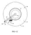
FIG. 2 is a side elevation view thereof. -
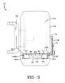
FIG. 3 is a front elevation view thereof; and -
FIG. 4 is an exploded perspective view of the bracket assembly. - Referring to
FIGS. 1-4 , the subject wheel andsensor assembly 10 is shown to include awheel assembly 12 in which atire 16 is mounted to arim 14 in conventional fashion. Theassembly 10 is a component of a vehicle (not shown) such as a passenger car or truck. However, as will be explained, the invention has particular utility in conjunction with measuring tire set-up and performance on a race car. Thetire 16 mounted torim 14 is, accordingly, intended to be of a general depiction without regard to vehicle type or use. Thetire 16 is of conventional construction having asidewall 18 extending to atread region 20. - The
assembly 10 further includes abracket assembly 22 mounted as shown to thewheel assembly 12. Thebracket assembly 22 generally is of U-shape defined by a firstbracket arm segment 24, a secondbracket arm segment 26 forming the bight of theassembly 22, and a thirdbracket arm segment 28. Each of thesegments segment 24 being in the form of a sized C-clamp 30. The segments formingbracket assembly 22 are formed from suitably sturdy material such as steel. Thefirst segment 24 has an elongatenarrow body 32 through which a longitudinal, medially located,slot 33 extends. Extending into an upper edge of thebody 32 is achannel 34. Thechannel 34 extends the length of thebody 32 and is sized to admit electrical wiring (not shown) used for power transmission to sensor units mounted to thebracket assembly 22 as well as data transmission from the sensor units as will be explained. - The
end segment 36 of thefirst segment 24 opposite the C-clamp 20 end angles inwardly to aremote flange 38 through which anassembly aperture 40 extends. Thesecond segment 26 of thebracket assembly 22 attaches to theflange 38. Thesecond segment 26 is of elongate construction, generally L-shaped in transverse sectional configuration. Thebracket segment 26 is formed by a horizontalelongate side 42 intersecting at a right angle along a longitudinal edge with avertical side 44. Thesides triangular end flanges 46 through which assembly apertures 48 pass. Suitable assembly hardware is provided to affix thesegment 26 to the first andthird segments nuts 49 A, B respectively. Spaced apartapertures 50 extend through theside 44 and serve as mounting locations for sensor device(s) attaching to theside 44 as will be explained. Assembly hardware such aspins 51 are provided for the attachment of sensor units to theside 44. - A
mounting plate 52 is included within thebracket assembly 22 and attaches to thebody 32 of thearm segment 24. Theplate 52 includes a verticalcoupling tongue projection 53 having spaced apartelongate mounting slots 54 extending therethrough. Arectangular plate body 56 has appropriately located mounting throughapertures 58 sized for attachment hardware such aspins 60. Asensor device 62 mounts to theplate body 56 by means of extension of thepins 60 through theapertures 58. Thesensor device 62 is preferably but not necessarily of the type used to measure slip angle of a tire such as a commercial product sold by Corrsys-Datron Co. The slipangle sensor device 62 mounts to the mountingplate 52. Theplate 52 attaches by set screws 55 extending throughplate slots 54 and through theslot 33 along thearm body 32. So attached, theplate 52 and slipangle sensor device 62 affixed thereto depend from thearm body 32 and are repositionable along thearm slot 33 into an optimal location relative to the ground surface for tire slip angle measurement. - A camber angle sensor device is assembled to include a pair of spaced apart
laser units second arm segment 26. Thesensor device tire 16 and are of a commercially available type sold by Corrsys-Datron Co. Thelaser units second arm segment 26. The attachment of theslip angle sensor 62 andcamber angle sensors arm segments FIGS. 1-3 . To attach the completedbracket assembly 22 with thesensor units wheel assembly 12, theU-shaped bracket assembly 22 is positioned in straddling relationship with thetire 16. The ends of thesegments wheel assembly 12 on opposite respective sides of thetire 16. In the assembled position, thearm segments opposite sidewalls 18 of thetire 16 and thearm segment 26 extends in an axial direction opposite thetread region 20 of the tire16. The spacing of thearm segments respective sidewalls 18 is preferably closely adjacent, in the range of from 1 mm to 15 mm, preferably 2 to 10 mm, or less to position theslip angle sensor 62 as close as possible to the tire sidewall. The close relationship of thesensor 62 with thetire sidewall 18 serves to enhance the accuracy of the slip angle measurement as well as reduce the extent to which thesensor 62 protrudes from the tire. Minimizing the protrusion of thesensor 62 acts to minimize the potential for damaging contact between thesensor 62 and surrounding objects. Thesensor 62 includes a downwardly directed laser element that measures the angle of thetire 16 relative to the ground surface during vehicle operation and thereby provides data for the calculation of the slip angle of the tire. - The location of the
second arm segment 26 and thecamber angle sensor tread region 20 of thetire 16, at a distance of from 1 mm to 15 mm, preferably 2 to 8 mm, or less. Such proximity enhances the accuracy of the camber angle measurement. The mounting of thearm segment 26 is preferable to the side of thewheel assembly 12 opposite the direction offorward vehicle travel 78 in order to protect thearm segment 26 andsensor passages 60 through thearm segment 26 provide air flow pathways from the rotating tire through thearm segment 26, whereby reducing drag, reducing stresses on thesegment 26 andsensor sensor units - While the
subject bracket assembly 22 and sensor units mounted thereto can effect measurement from tires used in myriad vehicle applications, the assembly is particularly useful and effective in determining the wheel and tire set up in a race car in preparation for a race. The coupling C-clamp 30 of theassembly 22 may be affixed to thestator 74 of aload cell 72 within thewheel assembly 12 as shown. A load cell such as shown at 72 is commercially available.Theopposite arm segment 28 of thebracket assembly 22 may attach to thebrake assembly 76 on the opposite side of the wheel. So located and attached, thesensors tire 16 to generate accurate camber and slip angle data as well as to minimize the degree to which bracket and sensors protrude. Vehicles may be, in the course of normal operation, particularly in race cars, driven close to outside obstructions and other vehicles. The close proximity and location of the bracket and sensors of the invention to the tire minimizes the risk of contact with such outside influences. Location of the second arm segment and sensor behind the tire, on the opposite side of normatively forward direction oftravel 78, likewise protects the bracket and sensor assembly. - While the attach points of the bracket assembly to the
wheel assembly 12 are preferably as shown, other means and locations of attachment of the bracket may be employed if desired. In addition, while slip angle and camberangle sensor units bracket assembly 22 and deployment scheme. For example, without intent to delimit the invention, a tire deflection detector or camera may be mounted to thebracket arm segments bracket assembly 22 to detect the thermal properties of a tire during vehicle use. Power to and data communication from such devices may be wired along thechannel 34 of thearm segment 24. The bracket assembly and deployment scheme described above allows for the measurement of thetire 16 while in actual use on a road surface. Such real time evaluation under actual working conditions results in a more thorough and accurate evaluation than laboratory testing. The bracket and sensors measure the tire under actual working conditions to provide not only information on tire performance but also tire response and reaction to a specific track or roadway. For a racecar, for example, specifically correlating tire response and conditional parameters to a particular racetrack is extremely important to the racecar setup. - In addition, mounting the
bracket assembly 22 and sensor units to asteer wheel assembly 12 allows for tire evaluation through turns since thebracket assembly 22 and sensor units will turn with the tire. Such capability effects a more thorough and accurate evaluation of the tire and roadway surface than could otherwise be made by the mounting of slip angle and camber angle sensors on the body of the vehicle adjacent to a tire. The subject bracket and sensor assembly turns with the wheel to which it is mounted and measure the slip angle directly as opposed vehicle based sensors that measure the slip angle base on the entire car chassis. Improved accuracy therefore is achieved by the invention assembly. - The
channel 34 formed within thearm segment 24 extends the length of thebody 32 and is sized to admit electrical wiring (not shown) used for power transmission tosensor units
Claims (15)
- A wheel and sensor assembly for a vehicle comprising:a rotational wheel assembly (12) operatively mounting to a vehicle andincluding a wheel rim (14) and a tire (16) mounted thereto ;at least one sensor device (66, 68, 62) for operatively measuring a wheel assembly parameter at least partially while the wheel assembly rotates in operational use on the vehicle;a bracket assembly (22) operatively carried by the wheel assembly (12), the at least one sensor device (62, 66, 68) mounting to the bracket assembly (22) in an operative location.
- The wheel and sensor assembly of claim 1, wherein the at least one sensor device (66, 68) is selected from a group of sensor devices including: camber sensors; slip angle sensors; tire deflection sensors; imaging units; cameras; thermal sensors.
- The wheel and sensor assembly of claim 1 or 2, wherein a plurality of sensor devices (62, 66, 68) mount to respective mounting locations on the bracket assembly (22).
- The wheel and sensor assembly of at least one of the previous claims, wherein the bracket assembly (22) includes a first bracket arm segment (24) extending at least partially opposite an outer sidewall (18) of the tire (16) in a radial direction, preferably at a spatial distance of from 2 mm to 15 mm, alternatively 3 to 10 mm, or less, from the outer sidewall (18) of the tire (16).
- The wheel and sensor assembly of at least one of the previous claims, wherein the bracket assembly (22) includes a second bracket arm segment (26) extending at least partially opposite a tread region (20) of the tire (16) in an axial direction, the wheel and sensor assembly (10) preferably including at least one secondary sensor device mounted to the second bracket arm segment (26) adjacent the tread region (20) of the tire (16).
- The wheel and sensor assembly of claim 5, wherein the second bracket arm segment (26) is operatively located on a tire side opposite a normatively forward vehicular direction of travel.
- The wheel and sensor assembly of claim 5 or 6, wherein the second bracket arm segment (26) includes at least one through passageway (60) establishing an airflow pathway through the second bracket arm segment (26).
- The wheel and sensor assembly of at least one of the previous claims, wherein the first and second bracket arm segments (24, 26) are mutually disposed at substantially a ninety degree angle.
- The wheel and sensor assembly of at least one of the previous claims, wherein the bracket assembly (22) includes a channel positioned to route electrical wiring along the bracket assembly and/or wherein a remote end of the first bracket arm segment (24) operatively connects to a stator from a load cell.
- The wheel and sensor assembly of at least one of the previous claims, wherein the bracket assembly (22) includes a third bracket segment (28) extending at least partially along an inner side of the wheel assembly (12) and connecting the second bracket segment (26) to an inward side of the wheel assembly (12).
- The wheel and sensor assembly of at least one of the previous claims, wherein the third bracket segment (28) operatively connects to a brake assembly.
- The wheel and sensor assembly of at least one of the previous claims, wherein the mounting fixture and the at least one sensor device (66, 68) operatively turn with the wheel assembly (12) to maintain the at least one sensor device in the operative position in the wheel assembly (12).
- The wheel and sensor assembly of at least one of the previous claims, wherein the at least one sensor device (66, 68, 62) is adjustably repositionable along the bracket assembly (12).
- The wheel and sensor assembly of at least one of the previous claims, wherein the first bracket arm segment (24) operatively maintains the at least one sensor device (66, 68, 62) in a spatial distance from a road surface and/or wherein the second bracket arm segment (26) maintains a secondary sensor device in an operative position.
- The wheel and sensor assembly of at least one of the previous claims, wherein the at least one sensor device operatively measures slip angle and the secondary sensor device operatively measures camber angle as the vehicle traverses a roadway.
Applications Claiming Priority (1)
| Application Number | Priority Date | Filing Date | Title |
|---|---|---|---|
| US12/251,850 US7775096B2 (en) | 2008-10-15 | 2008-10-15 | Wheel based sensor assembly |
Publications (1)
| Publication Number | Publication Date |
|---|---|
| EP2177380A2 true EP2177380A2 (en) | 2010-04-21 |
Family
ID=41460111
Family Applications (1)
| Application Number | Title | Priority Date | Filing Date |
|---|---|---|---|
| EP09171572A Withdrawn EP2177380A2 (en) | 2008-10-15 | 2009-09-29 | Wheel based sensor assembly |
Country Status (2)
| Country | Link |
|---|---|
| US (1) | US7775096B2 (en) |
| EP (1) | EP2177380A2 (en) |
Cited By (1)
| Publication number | Priority date | Publication date | Assignee | Title |
|---|---|---|---|---|
| WO2011131999A1 (en) * | 2010-04-23 | 2011-10-27 | Eamon Smyth | A device for detecting bulges in tyres |
Families Citing this family (6)
| Publication number | Priority date | Publication date | Assignee | Title |
|---|---|---|---|---|
| US8082777B2 (en) * | 2009-12-23 | 2011-12-27 | The Goodyear Tire & Rubber Company | Bearing assembly for wheel based sensor |
| CZ2011826A3 (en) * | 2011-12-15 | 2013-06-26 | Centrum dopravního výzkumu v.v.i. | Adjusting jig |
| US9132814B2 (en) * | 2012-09-18 | 2015-09-15 | Gm Global Technology Operationd Llc | Systems and methods for vibration mitigation in a vehicle |
| IT201900017498A1 (en) * | 2019-09-30 | 2021-03-30 | Trelleborg Wheel Sys Italia Spa | System for measuring the slippage of a tire with respect to a rim on which said tire is mounted, and relative method. |
| GB2602260A (en) * | 2020-12-16 | 2022-06-29 | Airbus Operations Ltd | Wheel assembly sensor apparatus |
| GB2602012A (en) | 2020-12-15 | 2022-06-22 | Airbus Operations Ltd | Tyre monitor |
Family Cites Families (1)
| Publication number | Priority date | Publication date | Assignee | Title |
|---|---|---|---|---|
| US4723444A (en) * | 1986-09-17 | 1988-02-09 | Jaroslav Hajek | Apparatus for determining side-slip characteristics of a moving vehicle |
-
2008
- 2008-10-15 US US12/251,850 patent/US7775096B2/en not_active Expired - Fee Related
-
2009
- 2009-09-29 EP EP09171572A patent/EP2177380A2/en not_active Withdrawn
Cited By (1)
| Publication number | Priority date | Publication date | Assignee | Title |
|---|---|---|---|---|
| WO2011131999A1 (en) * | 2010-04-23 | 2011-10-27 | Eamon Smyth | A device for detecting bulges in tyres |
Also Published As
| Publication number | Publication date |
|---|---|
| US20100089139A1 (en) | 2010-04-15 |
| US7775096B2 (en) | 2010-08-17 |
Similar Documents
| Publication | Publication Date | Title |
|---|---|---|
| US8082777B2 (en) | Bearing assembly for wheel based sensor | |
| US7775096B2 (en) | Wheel based sensor assembly | |
| US8661885B1 (en) | Tire sidewall load estimation system and method | |
| JP6650269B2 (en) | How to evaluate vehicle wheel condition | |
| CN112590795B (en) | Road surface condition estimating device and road surface condition estimating method using same | |
| US8869618B2 (en) | Method and apparatus for estimating contact patch shape of tire | |
| US20090080703A1 (en) | Optical systems and methods for determining tire characteristics | |
| US20150217607A1 (en) | Tire innerliner-based parameter estimation system and method | |
| KR100875405B1 (en) | A method and apparatus for detecting a decompression of a tire, and a computer-readable recording medium having recorded thereon a program for determining a decompression of a tire. | |
| US7579943B2 (en) | Apparatus, method and program for alarming decrease in tire air-pressure | |
| US20090106990A1 (en) | Dynamic axle alignment system onboard a vehicle | |
| JP7133458B2 (en) | Sound source identification method | |
| WO2024013495A1 (en) | A vehicle emissions sampling device for sampling emissions from a wheel and/or brake of a vehicle | |
| JP7106764B2 (en) | Tire deflection detection system | |
| JP6721134B2 (en) | Tire assembly and tire deformation state determination system | |
| CN113795415B (en) | Method and system for identifying unevenness of road surface | |
| KR20100067436A (en) | Apparatus of a test for run-flat tire | |
| US20030167832A1 (en) | Method and apparatus for measuring tire slippage | |
| JP2009115790A (en) | Method and apparatus for measuring angle of wheel and shaft | |
| CN117073583A (en) | Measuring device for measuring maximum width of turning channel | |
| KR20230097535A (en) | Device and Method for Estimating Alignment of Wheel of Vehicle | |
| CN116296474B (en) | Vehicle swing amplitude measuring device and method | |
| KR100300725B1 (en) | Attachment jig for wheel motion sensor | |
| US20240192022A1 (en) | System for real-time determination of calibration of an inertial measurement unit | |
| CN215373889U (en) | Suspension Standing Height Measuring Instrument Based on Chassis Hard Point |
Legal Events
| Date | Code | Title | Description |
|---|---|---|---|
| PUAI | Public reference made under article 153(3) epc to a published international application that has entered the european phase |
Free format text: ORIGINAL CODE: 0009012 |
|
| AK | Designated contracting states |
Kind code of ref document: A2 Designated state(s): AT BE BG CH CY CZ DE DK EE ES FI FR GB GR HR HU IE IS IT LI LT LU LV MC MK MT NL NO PL PT RO SE SI SK SM TR |
|
| AX | Request for extension of the european patent |
Extension state: AL BA RS |
|
| STAA | Information on the status of an ep patent application or granted ep patent |
Free format text: STATUS: THE APPLICATION HAS BEEN WITHDRAWN |
|
| 18W | Application withdrawn |
Effective date: 20120508 |