EP2177344A1 - Patch - Google Patents
Patch Download PDFInfo
- Publication number
- EP2177344A1 EP2177344A1 EP20090252427 EP09252427A EP2177344A1 EP 2177344 A1 EP2177344 A1 EP 2177344A1 EP 20090252427 EP20090252427 EP 20090252427 EP 09252427 A EP09252427 A EP 09252427A EP 2177344 A1 EP2177344 A1 EP 2177344A1
- Authority
- EP
- European Patent Office
- Prior art keywords
- patch
- fibers
- void
- structural fibers
- binder
- Prior art date
- Legal status (The legal status is an assumption and is not a legal conclusion. Google has not performed a legal analysis and makes no representation as to the accuracy of the status listed.)
- Withdrawn
Links
- 239000000835 fiber Substances 0.000 claims abstract description 53
- 238000000034 method Methods 0.000 claims abstract description 18
- 239000011230 binding agent Substances 0.000 claims abstract description 17
- OKTJSMMVPCPJKN-UHFFFAOYSA-N Carbon Chemical compound [C] OKTJSMMVPCPJKN-UHFFFAOYSA-N 0.000 claims abstract description 14
- 239000002041 carbon nanotube Substances 0.000 claims abstract description 14
- 229910021393 carbon nanotube Inorganic materials 0.000 claims abstract description 14
- 239000000463 material Substances 0.000 claims description 19
- 239000011800 void material Substances 0.000 claims description 12
- XQZYPMVTSDWCCE-UHFFFAOYSA-N phthalonitrile Chemical compound N#CC1=CC=CC=C1C#N XQZYPMVTSDWCCE-UHFFFAOYSA-N 0.000 claims description 5
- 229920006391 phthalonitrile polymer Polymers 0.000 claims description 5
- 239000012530 fluid Substances 0.000 claims description 4
- 229920000049 Carbon (fiber) Polymers 0.000 claims description 3
- 239000004917 carbon fiber Substances 0.000 claims description 3
- 230000008859 change Effects 0.000 claims description 3
- 239000002131 composite material Substances 0.000 claims description 3
- 239000003365 glass fiber Substances 0.000 claims description 2
- 239000011347 resin Substances 0.000 claims description 2
- 229920005989 resin Polymers 0.000 claims description 2
- 230000007547 defect Effects 0.000 claims 2
- 239000000945 filler Substances 0.000 claims 2
- 239000012790 adhesive layer Substances 0.000 claims 1
- 239000002184 metal Substances 0.000 claims 1
- 230000008569 process Effects 0.000 description 8
- 230000008439 repair process Effects 0.000 description 4
- 239000000853 adhesive Substances 0.000 description 2
- 230000001070 adhesive effect Effects 0.000 description 2
- 238000010586 diagram Methods 0.000 description 2
- ZOXJGFHDIHLPTG-UHFFFAOYSA-N Boron Chemical compound [B] ZOXJGFHDIHLPTG-UHFFFAOYSA-N 0.000 description 1
- 229910052796 boron Inorganic materials 0.000 description 1
- 238000011161 development Methods 0.000 description 1
- 230000018109 developmental process Effects 0.000 description 1
- 230000001788 irregular Effects 0.000 description 1
- 239000000203 mixture Substances 0.000 description 1
- 238000012986 modification Methods 0.000 description 1
- 230000004048 modification Effects 0.000 description 1
- 230000003647 oxidation Effects 0.000 description 1
- 238000007254 oxidation reaction Methods 0.000 description 1
- 230000001902 propagating effect Effects 0.000 description 1
- 239000000126 substance Substances 0.000 description 1
- 239000013589 supplement Substances 0.000 description 1
- 238000003466 welding Methods 0.000 description 1
Images


Classifications
-
- B—PERFORMING OPERATIONS; TRANSPORTING
- B29—WORKING OF PLASTICS; WORKING OF SUBSTANCES IN A PLASTIC STATE IN GENERAL
- B29C—SHAPING OR JOINING OF PLASTICS; SHAPING OF MATERIAL IN A PLASTIC STATE, NOT OTHERWISE PROVIDED FOR; AFTER-TREATMENT OF THE SHAPED PRODUCTS, e.g. REPAIRING
- B29C73/00—Repairing of articles made from plastics or substances in a plastic state, e.g. of articles shaped or produced by using techniques covered by this subclass or subclass B29D
- B29C73/04—Repairing of articles made from plastics or substances in a plastic state, e.g. of articles shaped or produced by using techniques covered by this subclass or subclass B29D using preformed elements
- B29C73/10—Repairing of articles made from plastics or substances in a plastic state, e.g. of articles shaped or produced by using techniques covered by this subclass or subclass B29D using preformed elements using patches sealing on the surface of the article
-
- Y—GENERAL TAGGING OF NEW TECHNOLOGICAL DEVELOPMENTS; GENERAL TAGGING OF CROSS-SECTIONAL TECHNOLOGIES SPANNING OVER SEVERAL SECTIONS OF THE IPC; TECHNICAL SUBJECTS COVERED BY FORMER USPC CROSS-REFERENCE ART COLLECTIONS [XRACs] AND DIGESTS
- Y10—TECHNICAL SUBJECTS COVERED BY FORMER USPC
- Y10T—TECHNICAL SUBJECTS COVERED BY FORMER US CLASSIFICATION
- Y10T428/00—Stock material or miscellaneous articles
- Y10T428/20—Patched hole or depression
-
- Y—GENERAL TAGGING OF NEW TECHNOLOGICAL DEVELOPMENTS; GENERAL TAGGING OF CROSS-SECTIONAL TECHNOLOGIES SPANNING OVER SEVERAL SECTIONS OF THE IPC; TECHNICAL SUBJECTS COVERED BY FORMER USPC CROSS-REFERENCE ART COLLECTIONS [XRACs] AND DIGESTS
- Y10—TECHNICAL SUBJECTS COVERED BY FORMER USPC
- Y10T—TECHNICAL SUBJECTS COVERED BY FORMER US CLASSIFICATION
- Y10T428/00—Stock material or miscellaneous articles
- Y10T428/249921—Web or sheet containing structurally defined element or component
- Y10T428/249924—Noninterengaged fiber-containing paper-free web or sheet which is not of specified porosity
Definitions
- the invention relates to a patch for repairing metallic or composite structures.
- the fibers 18 can be carbon fibers, such as IM-7 fibers provided by the Hexcel® Corporation, or glass fibers, boron fibers, or any similar fibers.
- the fibers 18 are structural in the sense that the fibers 18 can enhance the load-carrying characteristics of the structure 10 around the damaged area. For example, when the patch 16 is affixed to the structure 10, the fibers 18 can assist the structure 10 in preventing expansion of the damage.
- the patch 16 also includes a quantity of binder 20 at least partially encapsulating the plurality of structural fibers 18.
- the binder 20 can be a resin.
- the binder 20 can be phthalonitrile or a mixture containing phthalonitrile.
- the binder 20 can be chosen to match the coefficient of thermal expansion of the structure 10 and also match other properties of the underlying structure 10.
- a first or base patch 16a can be bonded to the surface 14a over the aperture 26a.
- the base patch 16a can extend between lateral edges 50a, 52a, and between axial edges 54a, 56a.
- the base patch 16a includes a plurality of structural fibers 18a (only a portion of the fibers 18a are shown to enhance the clarity of Figure 5 ).
- the fibers 18a are generally oriented in a direction parallel to the lateral edges 50a, 52a and oblique to a longitudinal axis 58a of the aperture 26a in the top plane.
- the aperture 26a also has longitudinal axis 59a in the side plane, as shown in Figure 6 . It is noted that the cross-sectional area of the patch 16a, or any of exemplary patch for practicing the invention, can be any desired value and any desired shape.
- the base patch 16a can be fully bonded to the surface 14a with nanoglue.
- the exemplary structure 10a can be a component of an aircraft, such as a vanebox at least partially defining a path for a fluid stream for propelling the aircraft represented by arrow 66a in Figure 6 .
- the exemplary structure 10a can therefore be subjected to relatively high tensile loads and orienting the patches 16a, 16b. 16c differently from one another can therefore be desirable.
- the exemplary patches 16a, 16b, 16c can be desirable because, as set forth above, each patch can be relatively thin. Thus, a single patch or a layered structure of a plurality of patches will minimally disturb the flow of the fluid stream.
Landscapes
- Engineering & Computer Science (AREA)
- Mechanical Engineering (AREA)
Abstract
A patch for repairing damaged structures is disclosed herein. The patch includes a plurality of structural fibers. The patch also includes a quantity of binder at least partially encapsulating the plurality of structural fibers. The patch also includes a plurality of carbon nanotubes substantially encapsulated in the binder with the plurality of structural fibers. An inventive and exemplary method for using the patch is also disclosed.
Description
- The invention relates to a patch for repairing metallic or composite structures.
- Structures employed in the aerospace industry and in other operating environments are sometimes damaged during operation. Patches can be used to repair damage so that fully replacing the damaged structure is not required. A patch can be a sheet of material that is fixed the damaged structure by welding or fasteners.
- In summary, the invention is a patch for repairing damaged structures. The patch includes a plurality of structural fibers. The patch also includes a quantity of binder at least partially encapsulating the plurality of structural fibers. The patch also includes a plurality of carbon nanotubes substantially encapsulated in the binder with the plurality of structural fibers. An inventive and exemplary method for using the patch is also disclosed.
- Advantages of the present invention will be readily appreciated as the same becomes better understood by reference to the following detailed description when considered in connection with the accompanying drawings wherein:
-
Figure 1 is a perspective view of an exemplary damaged structure; -
Figure 2 is a view showing a magnified portion of the exemplary damaged structure with a patch being positioned over the damaged portion of the structure; -
Figure 3 is a simplified flow diagram of one method for practicing the invention; -
Figure 4 is a cross-sectional view through a repaired portion of a structure according to an exemplary embodiment of the invention; -
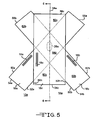
Figure 5 is a top view of a repaired portion of a structure according to an exemplary embodiment of the invention; and -
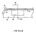
Figure 6 is a cross-sectional taken along section lines 6 - 6 inFigure 5 . - A plurality of different embodiments of the invention is shown in the Figures of the application. Similar features are shown in the various embodiments of the invention. Similar features have been numbered with a common reference numeral and have been differentiated by an alphabetic suffix. Similar features are structured similarly, operate similarly, and/or have the same function unless otherwise indicated by the drawings or this specification. Furthermore, particular features of one embodiment can replace corresponding features in another embodiment or can supplement other embodiments unless otherwise indicated by the drawings or this specification.
- Referring now to
Figure 1 , a structure orbody 10 includes aregion 12 of damage. Theexemplary structure 10 can be a vanebox associated with an aircraft. Generally, a vanebox can direct a stream of air for propelling or positioning the aircraft, such as in short and/or vertical take-offs and landings. It is noted that the present invention is not limited to repairing vaneboxes and that alternative embodiments of the invention can be practiced with structures used for other purposes. - In the first exemplary embodiment of the invention, debris can be drawn into the vanebox and strike the
surface 14, causing theregion 12 of damage. Theregion 12 of damage can be a through-hole in afirst surface 14 of thestructure 10. Alternatively, theregion 12 of damage can be any other form of void or surface marring. Damage can be defined differently in various operating environments and for various structures. The invention and embodiments thereof are not limited to the repair of any particular kind of damage. - Referring now to
Figure 2 , apatch 16 can be applied to thesurface 14 to repair theregion 12 of damage. Theexemplary patch 16 can be approximately 0.010 inch thick, but can be formed to a different thickness in alternative embodiments of the invention.Figure 4 shows that thepatch 16 can include a plurality ofstructural fibers 18. Thefibers 18 are illustrated inFigure 4 coming into and out of the page, extending generally parallel to one another. However, less than all thefibers 18 can be parallel to one another. The arrangement shown inFigure 4 , in which thefibers 18 in both top andbottom patches 16 extend parallel to one another, can be modified such thatfibers 18 in one of thepatches 16 extend transverse or oblique to thefibers 18 in theother patch 16. For example, the orientation of thebottom patch 16 inFigure 4 could be changed so that thefibers 18 of thatpatch 16 extend across the page rather than out of the page. - The
fibers 18 can be carbon fibers, such as IM-7 fibers provided by the Hexcel® Corporation, or glass fibers, boron fibers, or any similar fibers. Thefibers 18 are structural in the sense that thefibers 18 can enhance the load-carrying characteristics of thestructure 10 around the damaged area. For example, when thepatch 16 is affixed to thestructure 10, thefibers 18 can assist thestructure 10 in preventing expansion of the damage. - The
patch 16 also includes a quantity ofbinder 20 at least partially encapsulating the plurality ofstructural fibers 18. Thebinder 20 can be a resin. Thebinder 20 can be phthalonitrile or a mixture containing phthalonitrile. Thebinder 20 can be chosen to match the coefficient of thermal expansion of thestructure 10 and also match other properties of theunderlying structure 10. - The
patch 16 also includes a plurality of carbon nanotubes substantially encapsulated in thebinder 20 with the plurality ofstructural fibers 18. The carbon nanotubes can be dispersed generally evenly throughout thebinder 20 or can be concentrated in particular areas of thepatch 16 if desired. The carbon nanotubes can enhance the strength to thepatch 16. Also, for metallic structures, the carbon nanotubes can allow thepatch 16 to behave similarly as the structure, such as in thermal and electrical conductivity. The amount of carbon nanotubes added to thebinder 20 can be about 2-3% by weight, or can be added in some other amount Theexemplary structure 10 can be metallic, but the invention can also be practiced to repair composite bodies that have incurred damage. -
Figure 3 is a simplified flow diagram according to an exemplary embodiment of the invention. The process starts atstep 22. Referring to bothFigures 3 and4 , atstep 24 of the exemplary process, material can be removed from thestructure 10 to change theregion 12 of damage (shown inFigure 2 ) in thesurface 14 from a generally irregular shape into anaperture 26 extending through thestructure 10 from thefirst surface 14 to asecond surface 28.Step 24 can be desirable to eliminate the possibility of stress concentrations and also to prevent cracks from propagating through thestructure 10. The damaged area of thestructure 10 can be modified in other ways in alternative embodiments of the invention. For example, the damage 12 (shown inFigure 2 ) can be transformed into a blind aperture, a notch, a truncated conical recess, or any other shape. - At
step 30 of the exemplary process, thesurface 14 around theaperture 26 can be sanded and treated to promote adherence of thepatch 16 to thesurface 14. Other processes can be applied to the surface, such as grinding, abrading or lapping, as desired.Figure 2 shows an area 32 that has been sanded and treated. The area 32 can be larger than thepatch 16. Thesurface 14 can be treated by being coated after sanding to prevent oxidation, such as by alodining. - Referring again to
Figures 3 and4 , atstep 34 of the exemplary process, at least onepatch 16 can be applied on thesurface 14 over theaperture 26. Thepatch 16 can be bonded to thesurface 14 withnanoglue 36. Nanoglue was developed was developed by researchers at Rensselaer Polytechnic Institute and can bond materials that don't normally adhere to one another. Nanoglue is based on self-assembling nanoscale chains less than a nanometer thick. Nanoglue is commercially available and recent developments have occurred in which the adhesive capabilities can be enhanced. Nanoglue can define a bond between two structures, such as thestructure 10 and thepatch 16 that strengthens as temperature increases. Other forms of adhesive can be applied as desired. - At
step 38 of the exemplary process, fillmaterial 40 can be directed into theaperture 26. Thefill material 40 can be any appropriate material or combination of materials in view of the operating environment of the structure being repaired and in view of the chemical/metallurgical nature of thestructure 10 being repaired. In the exemplary embodiment of the invention, thefill material 40 can include phthalonitrile and a plurality of carbon nanotubes. Thefill material 40 can also include other components if desired. - At
step 42 of the exemplary process, any of thefill material 40 protruding beyond thesecond surface 28 can be sanded so that thefill material 40 is flush with the surroundingsurface 28. Atstep 44, thesurface 28 around theaperture 26 can be sanded and treated to promote adherence of apatch 16 to thesurface 28. Atstep 46, apatch 16 can be applied to thesurface 28 of thestructure 10. Thepatch 16 can be bonded to thesurface 28 over theaperture 26 withnanoglue 36. The exemplary process ends atstep 48. -
Figures 5 and6 show another embodiment of the invention in which a plurality ofpatches Figure 5 is a top view of a portion of a repairedstructure 10a.Figures 6 is a partial cross-section taken along section lines 6 - 6 inFigure 5 , showing the cross-section immediately around a repaired portion of thestructure 10a. As shown inFigure 6 , thestructure 10a was damaged and a void in the form of ablind aperture 26a was formed in thestructure 10a to change an irregularly-shaped region of damage into a known shape. - A first or
base patch 16a can be bonded to thesurface 14a over theaperture 26a. As shown inFigure 5 , thebase patch 16a can extend betweenlateral edges axial edges base patch 16a includes a plurality ofstructural fibers 18a (only a portion of thefibers 18a are shown to enhance the clarity ofFigure 5 ). Thefibers 18a are generally oriented in a direction parallel to thelateral edges longitudinal axis 58a of theaperture 26a in the top plane. Theaperture 26a also haslongitudinal axis 59a in the side plane, as shown inFigure 6 . It is noted that the cross-sectional area of thepatch 16a, or any of exemplary patch for practicing the invention, can be any desired value and any desired shape. Thebase patch 16a can be fully bonded to thesurface 14a with nanoglue. - As shown in
Figure 6 , a second orintermediate patch 16b can be positioned over thebase patch 16a. As shown inFigure 5 , theintermediate patch 16b can extend betweenlateral edges axial edges intermediate patch 16b includes a plurality ofstructural fibers 18b (only a portion of thefibers 18b are shown to enhance the clarity ofFigure 5 ). Thefibers 18b are generally oriented in a direction parallel to thelateral edges longitudinal axis 58a of theaperture 26a in the top plane. - The
intermediate patch 16b can be partially bonded to thesurface 14a and extend over theaperture 26a. For example, a portion 60b of theintermediate patch 16b bounded byaxial edge 54b,lateral edges lateral edge 52a of thebase patch 16a can be bonded to thesurface 14a. Also, aportion 62b of theintermediate patch 16b bounded by axial edge56b,lateral edges lateral edge 50a of thebase patch 16a can be bonded to thesurface 14a. The remainder of theintermediate patch 16b, bounded bylateral edges base patch 16a. Theintermediate patch 16b can be partially bonded to thesurface 14a and partially bonded to the top surface of thebase patch 16a with nanoglue. - As shown in
Figure 6 , a third ortop patch 16c can be positioned over thebase patch 16a and theintermediate patch 16b. As shown inFigure 5 , thetop patch 16c can extend betweenlateral edges axial edges top patch 16c includes a plurality ofstructural fibers 18c (only a portion of thefibers 18c are shown to enhance the clarity ofFigure 5 ). Thefibers 18c are generally oriented in a direction parallel to thelateral edges longitudinal axis 58a of theaperture 26a in the top plane. - The
top patch 16c can be partially bonded to thesurface 14a. For example, aportion 60c of thetop patch 16c bounded byaxial edge 54c,lateral edges lateral edge 52a of thebase patch 16a, and thelateral edge 50b of theintermediate patch 16b can be bonded to thesurface 14a with nanoglue. Also, aportion 62c of thetop patch 16c bounded byaxial edge 56c,lateral edges lateral edge 50a of thebase patch 16a, and thelateral edge 52b of theintermediate patch 16b can be bonded to thesurface 14a. Athird portion 64c of thetop patch 16c, bounded bylateral edge intermediate patch 16b with nanoglue. - The
patches fibers structural fibers 18a of thepatch 16a can be non-parallel to a majority of thestructural fibers 18b of thepatch 16b and also non-parallel to a majority of thestructural fibers 18c of thepatch 16c. Such an embodiment of the broader invention can be desirable to enhance the strength of the repairedstructure 10a. Thefibers structure 10a stronger than thestructure 10 prior to being damaged. - The
exemplary structure 10a can be a component of an aircraft, such as a vanebox at least partially defining a path for a fluid stream for propelling the aircraft represented byarrow 66a inFigure 6 . Theexemplary structure 10a can therefore be subjected to relatively high tensile loads and orienting thepatches exemplary patches - The exemplary embodiments of the invention disclose patches having a plurality of structural fibers extending substantially parallel with one another. Some of the fibers may not parallel with the majority of the other fibers. However, it is noted that in alternative embodiments of the invention, the structural fibers can be more randomly oriented. Also, the fibers can be arranged in patterns different than parallel to one another and still define an embodiment of the invention. For example, the fibers can be positioned in a wheel-like arrangement with a hub and spoke pattern.
- While the invention has been described with reference to an exemplary embodiment, it will be understood by those skilled in the art that various changes may be made and equivalents may be substituted for elements thereof without departing from the scope of the invention. In addition, many modifications may be made to adapt a particular situation or material to the teachings of the invention without departing from the essential scope thereof. Therefore, it is intended that the invention not be limited to the particular embodiment disclosed as the best mode contemplated for carrying out this invention, but that the invention will include all embodiments falling within the scope of the appended claims. Also, while this document may draw attention to certain features believed to be of particular importance, it should be understood that the Applicant claims protection in respect of any patentable feature or combination of features hereinbefore referred to and/or shown in the drawings whether or not particular emphasis has been placed thereon.
Claims (15)
- A patch for repairing damaged structures comprising:a plurality of structural fibers;a quantity of binder at least partially encapsulating said plurality of structural fibers; anda plurality of carbon nanotubes substantially encapsulated in said binder with said plurality of structural fibers.
- The patch of claim 1, wherein said plurality of structural fibers are further defined as being carbon fibers or glass fibers and/or wherein said binder is further defined as at least partially including phthalonitrile; and/or wherein the patch further comprises an adhesive layer of nanoglue.
- The patch of claim 1 or 2, wherein the combination of said plurality of structural fibers, said quantity of binder, and said plurality of carbon nanotubes is substantially 0.010 inch thick; and/or wherein at least a majority of said plurality of structural fibers extend substantially parallel with one another.
- A method of repairing a defect in a surface of a structure with the patch recited in claim 1 comprising the steps of:removing material from a structure to change a defect in a surface of the structure into a void of known shape;disposing fill material in the void; andapplying at least one patch on the surface over the void wherein the patch includes a plurality of structural fibers, a quantity of binder at least partially encapsulating the plurality of structural fibers, and a plurality of carbon nanotubes substantially encapsulated in the binder with the plurality of structural fibers.
- The method of claim 4, wherein said disposing step is further defined as disposing a fill material having carbon nanotubes in the void; or wherein said disposing step is further defined as disposing a fill material having phthalonitrile and carbon nanotubes in the void.
- The method of claim 4 or 5, further comprising the step of bonding the at least one patch to the surface with nanoglue.
- The method of any one of claims 4 to 6, wherein:said removing step includes the step of forming the void as a through-aperture in the structure; andsaid applying step includes the steps of:applying a first patch of patch across a first opening of the through-aperture; andapplying a second patch of patch across a second opening of the through-aperture opposite the first opening, wherein said disposing step is performed between said step of applying the first patch and said step of applying the second of patch.
- The method of any one of claims 4 to 7, wherein said applying step is further defined as:layering a plurality of patches on the surface over the void.
- The method of claim 8, further comprising the step of:orienting at least two of the patches in different directions relative to one another such that a majority of the structural fibers of one of the patches is non-parallel to a majority of the structural fibers of another one of the patches.
- An apparatus repaired according to the method of claim 7 and comprising:a body defining a void;a quantity of fill material disposed in said void; andat least one patch covering said void and said filler material.
- The apparatus of claim 10, wherein said filler material is a combination of resin and carbon nanotubes; and/or wherein said body is at least partially formed from metal or a composite material.
- The apparatus of claim 10 or 11, wherein said patch is further defined as including a plurality of carbon fibers oriented parallel to one another.
- The apparatus of any one of claims 9 to 12, wherein said body is further defined as a component of an aircraft.
- The apparatus of claim 13, wherein said body is a vanebox at least partially defining a path for a fluid stream propelling the aircraft.
- The apparatus of claim 14, wherein said at least one patch further comprises first and second patches oriented in different directions relative to the path for the fluid stream.
Applications Claiming Priority (1)
| Application Number | Priority Date | Filing Date | Title |
|---|---|---|---|
| US12/252,401 US20100098896A1 (en) | 2008-10-16 | 2008-10-16 | Patch |
Publications (1)
| Publication Number | Publication Date |
|---|---|
| EP2177344A1 true EP2177344A1 (en) | 2010-04-21 |
Family
ID=41566209
Family Applications (1)
| Application Number | Title | Priority Date | Filing Date |
|---|---|---|---|
| EP20090252427 Withdrawn EP2177344A1 (en) | 2008-10-16 | 2009-10-15 | Patch |
Country Status (2)
| Country | Link |
|---|---|
| US (1) | US20100098896A1 (en) |
| EP (1) | EP2177344A1 (en) |
Families Citing this family (1)
| Publication number | Priority date | Publication date | Assignee | Title |
|---|---|---|---|---|
| US10035323B2 (en) * | 2013-09-23 | 2018-07-31 | The Boeing Company | Composite textiles including spread filaments |
Citations (3)
| Publication number | Priority date | Publication date | Assignee | Title |
|---|---|---|---|---|
| US20020180077A1 (en) * | 2001-03-26 | 2002-12-05 | Glatkowski Paul J. | Carbon nanotube fiber-reinforced composite structures for EM and lightning strike protection |
| WO2006046974A2 (en) * | 2004-06-04 | 2006-05-04 | Cornerstone Research Group, Inc. | Method of making and using shape memory polymer composite patches |
| EP1775445A2 (en) * | 2005-10-11 | 2007-04-18 | United Technologies Corporation | Method of repair for inlet caps of turbine engines |
Family Cites Families (37)
| Publication number | Priority date | Publication date | Assignee | Title |
|---|---|---|---|---|
| US591822A (en) * | 1897-10-19 | curtis | ||
| US3509942A (en) * | 1966-08-15 | 1970-05-05 | John E Lindberg | System for detecting structural failure |
| US3979949A (en) * | 1975-06-30 | 1976-09-14 | The Boeing Company | Fatigue damage indicator |
| US4484132A (en) * | 1981-03-09 | 1984-11-20 | Crites Nelson A | Crack detecting system |
| US4503710A (en) * | 1983-06-08 | 1985-03-12 | Conoco Inc. | Crack detection by electrical resistance |
| US4591511A (en) * | 1984-07-30 | 1986-05-27 | The United States Of America As Represented By The Secretary Of The Navy | Adhesive repair patch |
| DE3429250C1 (en) * | 1984-08-08 | 1986-03-27 | Texas Instruments Deutschland Gmbh, 8050 Freising | Sensor responsive to the action of a force |
| US4759812A (en) * | 1985-07-11 | 1988-07-26 | Miller Robert W | Method and apparatus for effecting field repairs in stress carrying structures |
| GB2243412B (en) * | 1990-03-30 | 1994-11-23 | United Technologies Corp | Aircraft engine propulsor blade deicing |
| US5065630A (en) * | 1990-06-12 | 1991-11-19 | Grumman Aerospace Corporation | Integrated system for aircraft crack detection |
| DE69129944D1 (en) * | 1990-11-23 | 1998-09-10 | Akro Fireguard Prod Inc | FIRE-RESISTANT REPAIR PATCH AND METHOD FOR THE PRODUCTION THEREOF |
| US5698977A (en) * | 1993-10-12 | 1997-12-16 | The United States Of America As Represented By The Administrator Of The National Aeronautics And Space Administration | Eddy current method for fatigue testing |
| US20030088980A1 (en) * | 1993-11-01 | 2003-05-15 | Arnold James E. | Method for correcting defects in a workpiece |
| GB9409553D0 (en) * | 1994-04-28 | 1994-06-29 | British Aerospace | Crack detection system |
| JP3052047B2 (en) * | 1994-09-07 | 2000-06-12 | 本田技研工業株式会社 | Method of measuring stress of ferromagnetic metal body, method of measuring stress distribution in sheet-like sensor, and sheet-like sensor for measuring stress distribution |
| US5518565A (en) * | 1994-09-14 | 1996-05-21 | Northrop Grumman Corporation | Method of repairing a hole in a sheet member |
| US5958166A (en) * | 1996-12-31 | 1999-09-28 | Mcdonnell Douglas Corporation | Method for repairing high temperature composite structures |
| FR2763882B1 (en) * | 1997-05-29 | 1999-08-20 | Aerospatiale | ON-SITE REPAIR TOOLS OF A COMPOSITE STRUCTURE HAVING A DAMAGED AREA AND CORRESPONDING METHOD |
| FR2768994B1 (en) * | 1997-09-30 | 2001-12-21 | Deutsch Zentr Luft & Raumfahrt | PROFILE |
| FR2777496B1 (en) * | 1998-04-17 | 2000-08-04 | Sunkiss Aeronautique | PROCESS FOR OBTAINING, REPAIRING OR RECONSTRUCTING AN OBJECT WITH A PART OR COMPOSITE MATERIAL |
| US6759352B2 (en) * | 2001-07-05 | 2004-07-06 | Sony Corporation | Composite carbon fiber material and method of making same |
| US6656299B1 (en) * | 2001-12-19 | 2003-12-02 | Lockheed Martin Corporation | Method and apparatus for structural repair |
| US7167009B2 (en) * | 2002-04-16 | 2007-01-23 | Mide Technology Corporation | Method and apparatus for determining electrical properties of structures |
| US6820334B2 (en) * | 2002-04-19 | 2004-11-23 | General Electric Company | Method for repairing articles of ceramic composites |
| DE10223985A1 (en) * | 2002-05-29 | 2003-12-18 | Siemens Ag | Arrangement from a component and a control device, method for producing the arrangement and use of the arrangement |
| ITTO20020699A1 (en) * | 2002-08-06 | 2004-02-07 | Fiatavio Spa | VANE FOR THE STATOR OF A VARIABLE GEOMETRY TURBINE, |
| US7216428B2 (en) * | 2003-03-03 | 2007-05-15 | United Technologies Corporation | Method for turbine element repairing |
| US7310949B2 (en) * | 2003-11-07 | 2007-12-25 | General Electric Company | Method and apparatus for arresting a crack within a body |
| GB0428368D0 (en) * | 2004-12-24 | 2005-02-02 | Rolls Royce Plc | A composite blade |
| US7278830B2 (en) * | 2005-05-18 | 2007-10-09 | Allison Advanced Development Company, Inc. | Composite filled gas turbine engine blade with gas film damper |
| US7225681B2 (en) * | 2005-06-06 | 2007-06-05 | Texas Instruments Incorporated | Statistical method for identifying microcracks in insulators |
| US20070079507A1 (en) * | 2005-10-12 | 2007-04-12 | Kenny Cheng | Blade shroud repair |
| US7398698B2 (en) * | 2005-11-03 | 2008-07-15 | The Boeing Company | Smart repair patch and associated method |
| US7653994B2 (en) * | 2006-03-22 | 2010-02-02 | General Electric Company | Repair of HPT shrouds with sintered preforms |
| US20100009165A1 (en) * | 2008-07-10 | 2010-01-14 | Zyvex Performance Materials, Llc | Multifunctional Nanomaterial-Containing Composites and Methods for the Production Thereof |
| US8778487B2 (en) * | 2008-10-16 | 2014-07-15 | Rolls-Royce Corporation | Tape |
| US8202056B2 (en) * | 2008-10-16 | 2012-06-19 | Rolls-Royce Corporation | Morphable composite structure |
-
2008
- 2008-10-16 US US12/252,401 patent/US20100098896A1/en not_active Abandoned
-
2009
- 2009-10-15 EP EP20090252427 patent/EP2177344A1/en not_active Withdrawn
Patent Citations (3)
| Publication number | Priority date | Publication date | Assignee | Title |
|---|---|---|---|---|
| US20020180077A1 (en) * | 2001-03-26 | 2002-12-05 | Glatkowski Paul J. | Carbon nanotube fiber-reinforced composite structures for EM and lightning strike protection |
| WO2006046974A2 (en) * | 2004-06-04 | 2006-05-04 | Cornerstone Research Group, Inc. | Method of making and using shape memory polymer composite patches |
| EP1775445A2 (en) * | 2005-10-11 | 2007-04-18 | United Technologies Corporation | Method of repair for inlet caps of turbine engines |
Non-Patent Citations (2)
| Title |
|---|
| "Inexpensive "Nanoglue" Can Bond Nearly Anything Together", 1 May 2007 (2007-05-01), XP002566094, Retrieved from the Internet <URL:http://soenews.rpi.edu/update.do?artcenterkey=592> [retrieved on 20100128] * |
| BAKER A A ED - MIDDLETON DONALD H: "Repair Techniques for Composite Structures", 1 January 1990, COMPOSITE MATERIALS IN AIRCRAFT STRUCTURES, LONGMAN, NEW YORK, PAGE(S) 207 - 227, ISBN: 9780582017122, XP008103764 * |
Also Published As
| Publication number | Publication date |
|---|---|
| US20100098896A1 (en) | 2010-04-22 |
Similar Documents
| Publication | Publication Date | Title |
|---|---|---|
| RU2479465C2 (en) | Laminar composite structure | |
| EP1859922B1 (en) | Repair of composite sandwich structures with uneven bond surfaces and composite sandwich structure | |
| Kim et al. | Evaluation of fatigue characteristics for adhesively-bonded composite stepped lap joint | |
| CN102310593A (en) | The improved shop layer that is used for composite laminates successively decreases | |
| US9492975B2 (en) | Structural bonded patch with tapered adhesive design | |
| EP2527415A1 (en) | Conductive scrim embedded structural adhesive films | |
| EP2331612B1 (en) | Wrinkle reduction in uncured composite laminates | |
| US8926786B1 (en) | Composite panel and method of manufacturing the same | |
| US11858222B2 (en) | Method for applying a material to a fiber composite component | |
| JP6583966B2 (en) | Panel made of laminate and method for producing the same | |
| EP2551094A1 (en) | Bond and stitch repair for delaminated composite | |
| EP3349974B1 (en) | Method of repairing a composite material | |
| JP2016175331A (en) | Surface treatment method of composite material, joint structure, surface treatment unit for composite material, and joint processing unit | |
| EP2177344A1 (en) | Patch | |
| JP2009046931A (en) | Method for repairing steel material with carbon fiber reinforced resin plate, and repaired steel material | |
| CN110670725A (en) | Steel member assembly with fatigue strength and method of processing | |
| CN113007042A (en) | Blade repairing method of wind generating set, blade cementing structure and blade | |
| GB2485758A (en) | Method of forming a composite component by machining a frangible separation line | |
| Berczeli et al. | Improvement of adhesive joining of hybrid aluminum–GFRP using surface modifications | |
| US7192504B2 (en) | Adding glass to composite bonding surfaces | |
| JP7039401B2 (en) | Composite material and method of curing composite material | |
| EP4183560A1 (en) | A composite laminate and a method of manufacturing a composite laminate | |
| Achache et al. | Numerical Analysis of the Behavior of Structures Damaged by Fatigue and Repaired by Composite Patch |
Legal Events
| Date | Code | Title | Description |
|---|---|---|---|
| PUAI | Public reference made under article 153(3) epc to a published international application that has entered the european phase |
Free format text: ORIGINAL CODE: 0009012 |
|
| AK | Designated contracting states |
Kind code of ref document: A1 Designated state(s): AT BE BG CH CY CZ DE DK EE ES FI FR GB GR HR HU IE IS IT LI LT LU LV MC MK MT NL NO PL PT RO SE SI SK SM TR |
|
| AX | Request for extension of the european patent |
Extension state: AL BA RS |
|
| 17P | Request for examination filed |
Effective date: 20100421 |
|
| 17Q | First examination report despatched |
Effective date: 20130321 |
|
| STAA | Information on the status of an ep patent application or granted ep patent |
Free format text: STATUS: THE APPLICATION IS DEEMED TO BE WITHDRAWN |
|
| 18D | Application deemed to be withdrawn |
Effective date: 20130801 |