EP2177325A1 - Articulated structure of a multiple-axis robot and robot comprising such a structure - Google Patents
Articulated structure of a multiple-axis robot and robot comprising such a structure Download PDFInfo
- Publication number
- EP2177325A1 EP2177325A1 EP09173227A EP09173227A EP2177325A1 EP 2177325 A1 EP2177325 A1 EP 2177325A1 EP 09173227 A EP09173227 A EP 09173227A EP 09173227 A EP09173227 A EP 09173227A EP 2177325 A1 EP2177325 A1 EP 2177325A1
- Authority
- EP
- European Patent Office
- Prior art keywords
- axis
- actuator
- axes
- forearm
- arm
- Prior art date
- Legal status (The legal status is an assumption and is not a legal conclusion. Google has not performed a legal analysis and makes no representation as to the accuracy of the status listed.)
- Granted
Links
- 210000000245 forearm Anatomy 0.000 claims abstract description 46
- 230000033001 locomotion Effects 0.000 claims description 29
- 230000005540 biological transmission Effects 0.000 claims description 6
- 238000005192 partition Methods 0.000 description 2
- BASFCYQUMIYNBI-UHFFFAOYSA-N platinum Chemical compound [Pt] BASFCYQUMIYNBI-UHFFFAOYSA-N 0.000 description 2
- 241000239290 Araneae Species 0.000 description 1
- 241000920340 Pion Species 0.000 description 1
- 230000000295 complement effect Effects 0.000 description 1
- 230000003750 conditioning effect Effects 0.000 description 1
- 238000006073 displacement reaction Methods 0.000 description 1
- 230000009977 dual effect Effects 0.000 description 1
Images


Classifications
-
- B—PERFORMING OPERATIONS; TRANSPORTING
- B25—HAND TOOLS; PORTABLE POWER-DRIVEN TOOLS; MANIPULATORS
- B25J—MANIPULATORS; CHAMBERS PROVIDED WITH MANIPULATION DEVICES
- B25J9/00—Programme-controlled manipulators
- B25J9/02—Programme-controlled manipulators characterised by movement of the arms, e.g. cartesian coordinate type
- B25J9/04—Programme-controlled manipulators characterised by movement of the arms, e.g. cartesian coordinate type by rotating at least one arm, excluding the head movement itself, e.g. cylindrical coordinate type or polar coordinate type
- B25J9/041—Cylindrical coordinate type
- B25J9/042—Cylindrical coordinate type comprising an articulated arm
-
- B—PERFORMING OPERATIONS; TRANSPORTING
- B25—HAND TOOLS; PORTABLE POWER-DRIVEN TOOLS; MANIPULATORS
- B25J—MANIPULATORS; CHAMBERS PROVIDED WITH MANIPULATION DEVICES
- B25J9/00—Programme-controlled manipulators
- B25J9/02—Programme-controlled manipulators characterised by movement of the arms, e.g. cartesian coordinate type
- B25J9/04—Programme-controlled manipulators characterised by movement of the arms, e.g. cartesian coordinate type by rotating at least one arm, excluding the head movement itself, e.g. cylindrical coordinate type or polar coordinate type
- B25J9/046—Revolute coordinate type
-
- B—PERFORMING OPERATIONS; TRANSPORTING
- B25—HAND TOOLS; PORTABLE POWER-DRIVEN TOOLS; MANIPULATORS
- B25J—MANIPULATORS; CHAMBERS PROVIDED WITH MANIPULATION DEVICES
- B25J9/00—Programme-controlled manipulators
- B25J9/10—Programme-controlled manipulators characterised by positioning means for manipulator elements
- B25J9/106—Programme-controlled manipulators characterised by positioning means for manipulator elements with articulated links
- B25J9/1065—Programme-controlled manipulators characterised by positioning means for manipulator elements with articulated links with parallelograms
-
- Y—GENERAL TAGGING OF NEW TECHNOLOGICAL DEVELOPMENTS; GENERAL TAGGING OF CROSS-SECTIONAL TECHNOLOGIES SPANNING OVER SEVERAL SECTIONS OF THE IPC; TECHNICAL SUBJECTS COVERED BY FORMER USPC CROSS-REFERENCE ART COLLECTIONS [XRACs] AND DIGESTS
- Y10—TECHNICAL SUBJECTS COVERED BY FORMER USPC
- Y10T—TECHNICAL SUBJECTS COVERED BY FORMER US CLASSIFICATION
- Y10T74/00—Machine element or mechanism
- Y10T74/20—Control lever and linkage systems
- Y10T74/20207—Multiple controlling elements for single controlled element
- Y10T74/20305—Robotic arm
- Y10T74/20317—Robotic arm including electric motor
-
- Y—GENERAL TAGGING OF NEW TECHNOLOGICAL DEVELOPMENTS; GENERAL TAGGING OF CROSS-SECTIONAL TECHNOLOGIES SPANNING OVER SEVERAL SECTIONS OF THE IPC; TECHNICAL SUBJECTS COVERED BY FORMER USPC CROSS-REFERENCE ART COLLECTIONS [XRACs] AND DIGESTS
- Y10—TECHNICAL SUBJECTS COVERED BY FORMER USPC
- Y10T—TECHNICAL SUBJECTS COVERED BY FORMER US CLASSIFICATION
- Y10T74/00—Machine element or mechanism
- Y10T74/20—Control lever and linkage systems
- Y10T74/20207—Multiple controlling elements for single controlled element
- Y10T74/20305—Robotic arm
- Y10T74/20329—Joint between elements
Definitions
- the present invention relates to an articulated multi-axis robot structure with at least three degrees of freedom, as well as to a multi-axis robot comprising such a structure.
- SCARA robots are suitable for working in a horizontal plane. It is sometimes appropriate that these robots can also perform movements in a vertical plane. In these robots, this vertical movement is generally provided by a ball screw system placed in the vicinity of the tool, that is to say at the end of the articulated structure commonly called "robot arm”. This results in significant inertia of this articulated structure, which limits the speed of movement of the tool. In addition, the size of a ball screw system can be inconvenient under certain conditions of use.
- the invention intends to remedy more particularly by proposing a new multi-axis articulated robot structure which comprises at least three degrees of freedom and whose inertia is sufficiently low to be compatible with speed displacements. high.
- This structure is characterized in that the third actuator is mounted on the base or on the arm.
- the inertia of the forearm is substantially reduced compared to the devices of the prior art, insofar as the forearm must not move the third actuator in its pivoting movements around of the second axis. This makes it possible to achieve high speeds of movement of the end of the articulated structure which carries a tool.
- the invention also relates to a multi-axis robot equipped with an articulated structure as mentioned above.
- a robot can operate at higher speeds than those of the state of the art.
- its life is increased.
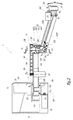
- Structure 1 visible to Figures 1 to 3 belongs to a multi-axis robot that also includes an electronic control unit, bundles of cables and / or pressurized gas supply conduit and other accessories that are not shown for clarity of the drawing. These elements are also not represented for the robots of the other embodiments.
- This structure 1 is intended to move to different positions, a tool 2 shown, schematically and in phantom only to the figure 1 , with trajectories extending both in a horizontal plane and perpendicular to this plane.
- the tool 2 may, for example, be a gripping tool.
- the structure 1 comprises a fixed base 10 relative to the room in which the structure 1 is installed. This base forms an articulation clevis of an arm 11 around a vertical axis Z 1 .
- the actuator 21 drives the arm 11 in rotation about the axis Z 1 .
- the arm 11 supports a forearm 12 which is articulated relative to the arm 11 about an axis Z 2 parallel to the axis Z 1 and therefore also vertical in the example shown.
- the forearm 12 comprises a first connecting rod, called the main connecting rod 121, and a second connecting rod, said secondary link or follower 122, which extend parallel to each other from a plate 123 belonging to the forearm 12 and mounted on the end 111 of the arm 11 farthest from the base 10.
- the forearm 12 also comprises a second plate 124 which supports a tool-holder flange 13 on which can be installed l 2.
- the plate 124 forms a reception case in which the flange 13 is mounted, pivotally about an axis Z 3 parallel to the axes Z 1 and Z 2 and which is a central axis of the flange 13.
- X 13 and X 23 are respectively noted the geometric axes of articulation of the connecting rods 121 and 122 on the plate 123.
- X 14 and X 24 are respectively noted the geometric axes of articulation of the connecting rods 121 and 122 on the plate 124.
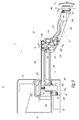
- the axes X 13 , X 23 , X 14 and X 24 are perpendicular to the axes Z 1 and Z 2 and define, in the plane of the figure 2 , a deformable parallelogram.
- the rods 121 and 122 and the plates 123 and 124 thus form a forearm structure 12 in the form of deformable or articulated parallelogram, which makes it possible to change the height of the flange 13, as represented by the double arrow F 1 to the figure 2 , while maintaining the orientation of the central axis Z 3 of the flange 13.
- the plate 123 is mounted on the end 111 of the arm 11 with the possibility of rotation about the axis Z 2 .
- the plate 123 is tubular in shape centered on the Z axis 2 in the mounted configuration of the structure 1.
- the plate 123 comprises two portions 125 and 126 of different diameters connected by a frustoconical portion 127.
- the arm 11 forms, in the vicinity of the end 111, a sleeve 112 centered on the axis Z 2 .
- the portion 125 of the plate 123 is disposed around a portion of the sleeve 112, with the interposition of two ball bearings 141 and 142 which allow the plate 123 to rotate around the sleeve 112 and the Z axis 2 .
- a central rod 151 of a pulley 15 is disposed inside the sleeve 112 and aligned on the axis Z 2 , with the interposition of two ball bearings 143 and 144.
- a second actuator 22 is mounted on the plate 10.
- the output shaft 221 of the actuator 22 extends along a horizontal axis Z 22 and has a pinion-shaped end which meshes with a toothed annular portion 161 of a pulley 162 rotatably mounted on the base 10 with the interposition of a ball bearing 145.
- the shaft 221 and the pulley 162 together form a 90 ° angle wheel.
- the axis of rotation Z 162 of the pulley 162 is, in the example shown, coincident with the axis Z 1 .
- the pulley 162 rotates a belt 163 which partially surrounds the portion 125 of the plate 123. It is thus possible to rotate the plate 123 around the Z axis 2 , thanks to a movement generated by the actuator 22 and transmitted through the elements 221, 161, 162 and 163. In other words, the actuator 22 controls the pivoting of the forearm 12 about the axis Z 2 .
- a third actuator 23 is mounted on the arm 11 and its output shaft 231 drives a belt 164 which surrounds the head of the pulley 15.
- the rod 151 At its end opposite the pulley head, the rod 151 carries a pinion 153 which is engaged with a toothed sector 128 integral with the connecting rod 121.
- the gear constituted by the parts 153 and 128 constitutes a 90 ° angle of rotation making it possible to transform the rotational movement of the pulley 15, around the axis Z 2 , into a pivoting movement of the connecting rod 121 about the X axis 13 .
- the gear formed of parts 153 and 128 may be of the type known as CILKRO (trade mark) which consists of an involute cut standard gear and a complementary gear wheel portion.
- CILKRO trade mark
- Such a gear has the advantage that its adjustment is simple since the position of the pinion 153 along its axis of rotation Z 2 does not need to be fixed precisely.
- Other types of gears at 90 ° can be used between the rod 151 and the connecting rod 121.
- a spring 171 is mounted in the portion 126 of the plate 123 and bears against a pin 172 secured to the main link 121, by exerting on it an elastic force E 1 which tends to raise the plate 124.
- the spring 171 can therefore be considered as a means of assisting the movement of the plate 124 upwards to the figure 2 .
- the spring 171 constitutes a means of compensation of the weight of the tool 2.
- a shaft 181 which extends along the X axis 13 constitutes the means of articulation of the connecting rod 121 on the plate 123.
- the spring 171 is mounted around the shaft 181.
- Two pins 182 and 183, which extend along the X axis 23 form the means of articulation of the connecting rod 122 on the plate 123.
- Shafts of the same type are used to form the articulation between the connecting rods 121 and 122 and the plate 124.
- the connecting rod 121 comprises a substantially vertical veil clearly visible at the figure 2 .
- the connecting rod 122 is box-shaped with a rectangular cross-section, with two vertical partitions 122A and 122B visible to the Figures 1 and 3 and two partitions 122C and 122D whose orientation varies as a function of the pivoting of the connecting rod 122 about the X axis 23 and which are visible at the figure 2 .
- the actuator 23 is an electric geared motor whose weight is supported by the arm 11, so that this weight does not hinder the movements of the forearm 12 and the flange 13, represented by the double arrows F 1 and F 2 at the figure 2 , which is particularly advantageous for achieving high speeds of movement of the tool 2.
- the axes Z 21 , Z 22 and Z 23 of the output shafts 211, 221 and 231 of the actuators 21, 22 and 23 are vertical and parallel to the axes Z 1 and Z 2 .
- the axes Z 1 and Z 21 are merged.
- connection by pulley 164 and 90 ° angle of return, between the actuator 23 and the connecting rod 121, makes it possible to use lightweight and low inertia equipment for driving the forearm 12 in the vertical movements of the flange. 13.
- the reduction ratio between the output shaft 231 and the connecting rod 121 is between 30 and 100.
- connection by pulleys 162 and 15 and by belt 163 makes it possible to use light and low inertia equipment to drive the forearm 12 to pivot about the axis Z 2 .
- a fourth actuator 24 is installed on the plate 124 and its output shaft 241 forms a pinion which drives a toothed annular surface 131 of the flange 13, which rotates the flange 13 and the tool 2 which it carries around the axis Z 3 .
- Two covers 191 and 192 are respectively mounted on the base 10, to protect the actuators 21 and 22, and on the arm 11, to protect the belt 164 and the head 152 of the pulley 15.
- the articulated structure 1 comprises a base 10, an arm 11 and a forearm 12 itself consisting of a first connecting rod 121, called the main connecting rod, of a second connecting rod 122, referred to as secondary, and two platens 123 and 124 forming a deformable parallelogram structure.
- Two actuators 21 and 22 are mounted on the base 10 so as to respectively pivot the arm 11 about a vertical axis Z 1 and the forearm 12 about a vertical axis Z 2 parallel to the axis Z 1 .
- the output shaft 211 of the actuator 21 is engaged with the arm 11 while the output shaft 221 of the actuator 22 is pinion-shaped and meshes with a toothed portion 161 of a Pulley 162.
- the elements 221 and 162 together form a 90 ° angle and the pulley 162 is rotated about an axis Z 162 aligned on the axis Z 1 .
- This pulley drives itself a belt 163 which rotates the plate 123 of the forearm 12 by which it is fixed on the end 111 of the arm 11.
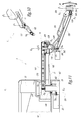
- a third actuator 23 is mounted on the base 10 and serves, as in the first embodiment, to drive the forearm 12 in its vertical movement of the plate 124 represented by the double arrow F 1 .
- the actuator 23 is installed in the center of the pulley 162 which is supported by the base 10 with the interposition of a bearing 145.
- the actuator 23 is fixedly mounted relative to the base 10, which is possible thanks to a radial clearance between this actuator and the pulley 162.
- the output shaft 231 of the actuator 23 drives a belt 164 which surrounds the head 152 of a pulley 15, as in the first embodiment.
- This pulley head 152 is secured to a rod 151 whose end carries a screw Endless 154 engaged with a wheel sector 129 secured to the main rod 121.
- X 13 , X 14 , X 23 and X 24 respectively denote the axes of articulation of the connecting rods 121 and 122 on the plates 123 and 124.
- the X axes 13 , X 14 , X 23 and X 24 are perpendicular to the Z 1 and Z 2 axes.
- the central axis Z 23 of the output shaft 231 is aligned with the central axis Z 21 of the output shaft 211, these axes being in fact coincides with the axis Z 1 .
- This configuration gives the structure 1 a great compactness, while allowing to drive the arm 11 and the forearm 12 quickly and accurately.
- the fact that the axes Z 23 , Z 162 and Z 1 are merged ensures that the center distance between the axes Z 23 , Z 162 and Z 2 remains constant, which ensures the tension noted of the belts 163 and 164.
- the plate 124 carries a fourth actuator 24. Its output shaft 241 forms a pinion which meshes with an annular toothing 131 of the flange 13, to drive this flange in rotation about an axis Z 3 parallel to the axes Z 1 and Z 2 .
- the forearm 12 is constituted by a first connecting rod 121, said main, shaped housing which surrounds a second connecting rod 122, said secondary.
- the connecting rod 121 is articulated, with the interposition of a ball bearing 146, around a sleeve 221 belonging to a plate 123.
- This rod 121 is integral with a shaft 222 from which extends a toothed sector 128 of the same type as that of the first embodiment and which is engaged with a pinion 153, also of the same type as that of the first embodiment, this allows to drive the connecting rod 121 in rotation about an axis X 13 perpendicular to the Z axis 2 of vertical articulation of the forearm 12 on the arm 11.
- auxiliary plates 223 and 224 are respectively secured to the plates 123 and 124, via pins 226 which pass through lights 225 formed in the main rod 121.
- the auxiliary plates 223 and 224 support the joints of the secondary link 122 about the X 23 and X 24 axes.
- the axes X 13 and X 23 remain fixed relative to each other, in the reference frame of the plate 123, as the X axes X 14 and X 24 , in the repository of the plate 124.
- a fourth actuator 24 is supported by the plate 124 with the axis of rotation Z 24 of its output shaft 241 parallel to the articulation axis Z 2 of the forearm 12 on the arm 11 and to the axis Z 3 rotation of the tool clamp.
- the shaft 241 is connected to the tool clamp 13 by a belt 165.
- the inertia of the end portion of the structure 1, which carries the flange 13, is further reduced by the fact that the fourth actuator 24 is mounted on the plate 123 of the forearm 12 by which this forearm is connected to the arm 11.
- a first rod 121 is rotated relative to the plate 123 and around an axis X 13 , in a manner comparable to that of the second embodiment, by means of belts 163 and 164 respectively driven. by second and third actuators, and a bevel gear angle transmission comprising a pinion 153 and a toothed sector 128.
- the output shaft 241 of the actuator 24 drives a fork 242 connected, by a not shown spider, to a first end 122E of the second connecting rod 122, called secondary or auxiliary.
- the second end 122F, opposite to the first, of the secondary link is connected, by another cross not shown, to a second fork 243 integral with a pinion 244 which drives a toothed surface 131 of the flange 13, in order to drive this flange rotates about a vertical axis Z 3 and parallel to the axis of articulation Z 2 of the forearm 12 on the arm 11.
- the articulation braces between the forks 242 and 243 and the connecting rod 122 make it possible to define the axes X 23 and X 24 .
- the X 13 and X 14 axes are defined by trees or pions, as in the previous embodiments.
- the secondary link 122 has a dual function: it constitutes the second link of the deformable parallelogram constituting the forearm 12 and transmits the rotational movement represented by the arrow F 3 , the fourth actuator 24 to the tool holder flange 13.
- the articulation between the elements 122, 242 and 243 can be considered as a double gimbal.
- the third and fourth embodiments function as the second.
- three actuators 21, 22 and 23 are mounted on a base 10 for driving the arm 11 around a vertical axis Z 1 and the forearm 12 about a vertical axis Z 2 and in a vertical pivot, around X 13 and X 23 axes.
- the forearm 12 forms a deformable parallelogram structure.
- a pinion mounted on the output shaft 221 of the actuator 22, a toothed portion 161 of the portion 162 and belts 163 and 164 make it possible to transmit the rotational movements respectively of the second actuator 22 to the plate 123, around the Z axis 2 , and the third actuator 23 to the first link 121, through the 90 ° angle gear 153/128.
- the actuators 21 to 24 are formed by electric rotary geared motors.
- a geared motor is not necessarily equipped with a clean reduction member, in which case the reduction ratio is equal to 1.
- the first connecting rod 121 is primary insofar as the actuator 23 primarily controls its pivoting about the X axis 13 . This pivoting induces the pivoting of the second link 122 which is therefore follower for this movement.
- the pivoting of the forearm 12 in height is thus controlled directly by the actuator 23, through the pulley 15, for the first connecting rod 121 and indirectly, through the connecting rod 121 and the plates 123 and 124, for the second connecting rod 122.
- the second actuator 22 may be mounted on the base with the axis of rotation of its output shaft parallel to the axis of rotation of the pulley 162.
- a belt is used to transmit movement between this actuator and this pulley.
- the actuator 22 controls the rotation of the forearm 12 about the Z axis 2 by means of two belts and an intermediate pulley.
- the bevel gear used to drive the main link 121 of the forearm may comprise a pair of bevel gears, spyro-conical, hypoid or CYLKRO type.
- a pair of hypoid gears the axes of rotation of the pinion and the toothed wheel are not intersecting. It can also be a worm system, as mentioned above.
- the structure of the invention allows the overall size of the robot, that is to say the envelope of the moving parts, to be small in a vertical direction, while allowing movements horizontal and vertical lines of significant amplitude.
Abstract
Description
La présente invention a trait à une structure articulée de robot multi-axes avec au moins trois degrés de liberté, ainsi qu'à un robot multi-axes comprenant une telle structure.The present invention relates to an articulated multi-axis robot structure with at least three degrees of freedom, as well as to a multi-axis robot comprising such a structure.
Dans le domaine des robots multi-axes, on doit parfois manipuler de façon rapide des pièces, suivant des trajectoires proches d'un plan. Tel est par exemple le cas lorsqu'il s'agit de prendre une pièce qui défile sur un tapis roulant et de la déposer sur un organe de conditionnement plan. Les robots de type SCARA sont adaptés au travail dans un plan horizontal. Il convient parfois que ces robots puissent également effectuer des mouvements dans un plan vertical. Dans ces robots, ce mouvement vertical est généralement assuré par un système de vis à billes placé au voisinage de l'outil, c'est-à-dire au bout de la structure articulée communément appelée « bras de robot ». Il en résulte une inertie importante de cette structure articulée, ce qui limite la vitesse de déplacement de l'outil. En outre, l'encombrement d'un système de vis à billes peut s'avérer gênant dans certaines conditions d'utilisation.In the field of multi-axis robots, we must sometimes manipulate parts quickly, following trajectories close to a plane. This is for example the case when it comes to take a piece that scrolls on a treadmill and deposit on a flat conditioning member. SCARA robots are suitable for working in a horizontal plane. It is sometimes appropriate that these robots can also perform movements in a vertical plane. In these robots, this vertical movement is generally provided by a ball screw system placed in the vicinity of the tool, that is to say at the end of the articulated structure commonly called "robot arm". This results in significant inertia of this articulated structure, which limits the speed of movement of the tool. In addition, the size of a ball screw system can be inconvenient under certain conditions of use.
Il est connu de
C'est à ces inconvénients qu'entend plus particulièrement remédier l'invention en proposant une nouvelle structure articulée de robot multi-axes qui comprend au moins trois degrés de liberté et dont l'inertie est suffisamment faible pour être compatible avec des déplacements à vitesse élevée.It is these drawbacks that the invention intends to remedy more particularly by proposing a new multi-axis articulated robot structure which comprises at least three degrees of freedom and whose inertia is sufficiently low to be compatible with speed displacements. high.
A cet effet, l'invention concerne une structure articulée de robot multi-axes avec au moins trois degrés de liberté, cette structure comprenant :
- une embase fixe,
- un bras articulé sur l'embase autour d'un premier axe,
- un avant-bras articulé sur le bras autour d'un deuxième axe parallèle au premier axe, cet avant-bras formant une structure en parallélogramme déformable et comprenant une première bielle et une deuxième bielle articulées sur deux platines, respectivement autour d'axes perpendiculaires au premier et au deuxième axes,
- un premier actionneur électrique commandant le pivotement du bras autour du premier axe,
- un deuxième actionneur électrique commandant le pivotement de l'avant-bras autour du deuxième axe, et
- un troisième actionneur électrique commandant le pivotement de la première bielle par rapport aux platines, autour de certains des axes perpendiculaires aux premier et deuxième axes.
- a fixed base,
- an articulated arm on the base around a first axis,
- a forearm articulated on the arm about a second axis parallel to the first axis, this forearm forming a deformable parallelogram structure and comprising a first connecting rod and a second connecting rod articulated on two plates, respectively about axes perpendicular to the first and second axes,
- a first electric actuator controlling the pivoting of the arm around the first axis,
- a second electric actuator controlling the pivoting of the forearm about the second axis, and
- a third electric actuator controlling the pivoting of the first link relative to the plates, around some of the axes perpendicular to the first and second axes.
Cette structure est caractérisée en ce que le troisième actionneur est monté sur l'embase ou sur le bras.This structure is characterized in that the third actuator is mounted on the base or on the arm.
Grâce à l'invention, l'inertie de l'avant-bras est sensiblement diminuée par rapport aux dispositifs de l'art antérieur, dans la mesure où l'avant-bras ne doit pas déplacer le troisième actionneur dans ses mouvements de pivotement autour du deuxième axe. Ceci permet d'atteindre des vitesses de déplacement élevées de l'extrémité de la structure articulée qui porte un outil.Thanks to the invention, the inertia of the forearm is substantially reduced compared to the devices of the prior art, insofar as the forearm must not move the third actuator in its pivoting movements around of the second axis. This makes it possible to achieve high speeds of movement of the end of the articulated structure which carries a tool.
Selon des aspects avantageux mais non obligatoires de l'invention, une telle structure peut incorporer une ou plusieurs des caractéristiques suivantes, prises dans toute combinaison techniquement admissible :
- Le troisième actionneur est rotatif et son arbre de sortie est centré sur un axe parallèle au premier axe,
- Les moyens de transmission de mouvement entre le troisième actionneur et les bielles de l'avant-bras comprennent au moins une courroie et un renvoi d'angle à 90°. Ce renvoi d'angle peut comprendre un couple d'engrenages conique, spyro-conique, hypoïde ou de type CYLKRO (marque déposée) ou un système à roue et vis sans fin.
- Selon certains modes de réalisation, le troisième actionneur est monté sur le bras,
- Selon d'autres modes de réalisation, au moins les premier et troisième actionneurs sont montés sur l'embase. Dans ce cas, le troisième actionneur est avantageusement de type rotatif et l'axe de rotation de son arbre de sortie est aligné avec le premier axe. En outre, les premier et troisième actionneurs peuvent être de type rotatif et les axes de rotation de leurs arbres de sortie respectifs peuvent être alignés.
- L'une des deux bielles de l'avant-bras forme un boîtier qui entoure l'autre bielle,
- La structure comprend un quatrième actionneur qui commande le pivotement d'une bride porte-outil autour d'un quatrième axe parallèle aux premier et deuxième axes. Dans ce cas, on peut prévoir que la première bielle est solidaire en rotation, autour d'un des axes perpendiculaires aux premier et deuxième axes, de moyens de transmission d'un mouvement généré par le troisième actionneur, que la deuxième bielle est suiveuse de la première bielle dans le mouvement de pivotement des bielles par rapport aux platines, que le quatrième actionneur est monté sur une platine de l'avant-bras qui est articulée sur le bras, que la bride porte-outil est supportée par l'autre platine et que la deuxième bielle transmet à la bride porte-outil le mouvement généré par le quatrième actionneur.
- The third actuator is rotatable and its output shaft is centered on an axis parallel to the first axis,
- The movement transmission means between the third actuator and the forearm rods comprise at least one belt and a 90 ° angle gear. This bevel gear can include a pair of bevel gears, spyro-conical, hypoid or CYLKRO type (registered trademark) or a wheel and worm system.
- According to some embodiments, the third actuator is mounted on the arm,
- According to other embodiments, at least the first and third actuators are mounted on the base. In this case, the third The actuator is advantageously of rotary type and the axis of rotation of its output shaft is aligned with the first axis. In addition, the first and third actuators may be of the rotary type and the axes of rotation of their respective output shafts may be aligned.
- One of the two connecting rods of the forearm forms a housing which surrounds the other connecting rod,
- The structure includes a fourth actuator that controls the pivoting of a tool clamp around a fourth axis parallel to the first and second axes. In this case, it can be provided that the first connecting rod is integral in rotation, about one of the axes perpendicular to the first and second axes, of transmission means of a movement generated by the third actuator, that the second link is follower of the first rod in the pivoting movement of the rods relative to the plates, that the fourth actuator is mounted on a plate of the forearm which is articulated on the arm, the toolholder flange is supported by the other plate and that the second connecting rod transmits the movement generated by the fourth actuator to the toolholder flange.
L'invention concerne également un robot multi-axes équipé d'une structure articulée tel que mentionné ci-dessus. Un tel robot peut fonctionner à des vitesses plus élevées que ceux de l'état de la technique. En outre, compte-tenu des masses plus faibles en mouvement, sa durée de vie est augmentée.The invention also relates to a multi-axis robot equipped with an articulated structure as mentioned above. Such a robot can operate at higher speeds than those of the state of the art. In addition, given the lower masses in motion, its life is increased.
L'invention sera mieux comprise et d'autres avantages de celle-ci apparaîtront plus clairement à la lumière de la description qui va suivre de quatre modes de réalisation d'une structure articulée et d'un robot multi-axes conforme à son principe, donnée uniquement à titre d'exemples et faite en référence aux dessins annexés dans lesquels :
- la
figure 1 est une vue en perspective d'une structure articulée de robot multi-axes conforme à un premier mode de réalisation de l'invention, - la
figure 2 est une coupe longitudinale de la structure de lafigure 1 en configuration rectiligne, - la
figure 3 est une coupe à plus grande échelle selon la ligne III-III à lafigure 2 , - la
figure 4 est une vue analogue à lafigure 1 pour une structure conforme à un deuxième mode de réalisation de l'invention, - la
figure 5 est une coupe longitudinale, analogue à lafigure 2 , pour la structure de lafigure 4 , - la
figure 6 est une vue analogue à lafigure 1 pour une structure conforme à un troisième mode de réalisation de l'invention, - la
figure 7 est une coupe longitudinale, analogue à lafigure 2 , pour la structure de lafigure 6 , - la
figure 8 est une vue de dessus d'une partie du bras et de l'avant-bras de la structure desfigures 6 et7 ; on y a indiqué en VII-VII le plan de coupe de lafigure 7 , - la
figure 9 est une coupe à plus grande échelle selon la ligne IX-IX à lafigure 7 , - la
figure 10 est une vue analogue à lafigure 1 , à plus petite échelle, pour une structure conforme à un quatrième mode de réalisation de l'invention, et - la
figure 11 est une coupe longitudinale, analogue à lafigure 2 pour la structure de lafigure 10 .
- the
figure 1 is a perspective view of an articulated multi-axis robot structure according to a first embodiment of the invention, - the
figure 2 is a longitudinal section of the structure of thefigure 1 in rectilinear configuration, - the
figure 3 is a larger-scale section along the line III-III to thefigure 2 , - the
figure 4 is a view similar to thefigure 1 for a structure according to a second embodiment of the invention, - the
figure 5 is a longitudinal section, similar to thefigure 2 , for the structure of thefigure 4 , - the
figure 6 is a view similar to thefigure 1 for a structure according to a third embodiment of the invention, - the
figure 7 is a longitudinal section, similar to thefigure 2 , for the structure of thefigure 6 , - the
figure 8 is a top view of a part of the arm and forearm of the structure of thefigures 6 and7 ; in VII-VII, the cutting plane of thefigure 7 , - the
figure 9 is a larger-scale section along line IX-IX atfigure 7 , - the
figure 10 is a view similar to thefigure 1 , on a smaller scale, for a structure according to a fourth embodiment of the invention, and - the
figure 11 is a longitudinal section, similar to thefigure 2 for the structure of thefigure 10 .
La structure 1 visible aux
Cette structure 1 est destinée à déplacer vers différentes positions, un outil 2 représenté, de façon schématique et en traits mixtes uniquement à la
La structure 1 comprend une embase 10 fixe par rapport au local dans lequel est installée la structure 1. Cette embase forme une chape d'articulation d'un bras 11 autour d'un axe vertical Z1.The
Un premier actionneur 21, formé par un motoréducteur rotatif électrique dont l'arbre de sortie 211 est aligné sur l'axe Z1 et solidaire en rotation du bras 11, est monté sur l'embase 10. L'actionneur 21 entraîne le bras 11 en rotation autour de l'axe Z1.A
Le bras 11 supporte un avant-bras 12 qui est articulé par rapport au bras 11 autour d'un axe Z2 parallèle à l'axe Z1 et donc également vertical dans l'exemple représenté.The
L'avant-bras 12 comprend une première bielle, dite bielle principale 121, et une deuxième bielle, dite bielle secondaire ou suiveuse 122, qui s'étendent parallèlement l'une à l'autre à partir d'une platine 123 appartenant à l'avant-bras 12 et montée sur l'extrémité 111 du bras 11 la plus éloignée de l'embase 10. L'avant-bras 12 comprend également une deuxième platine 124 qui supporte une bride porte-outil 13 sur laquelle peut être installé l'outil 2. La platine 124 forme un fut de réception dans lequel est montée la bride 13, de façon pivotante autour d'un axe Z3 parallèle aux axes Z1 et Z2 et qui est un axe central de la bride 13.The
On note respectivement X13 et X23 les axes géométriques d'articulation des bielles 121 et 122 sur la platine 123. On note respectivement X14 et X24 les axes géométriques d'articulation des bielles 121 et 122 sur la platine 124. Les axes X13, X23, X14 et X24 sont perpendiculaires aux axes Z1 et Z2 et définissent, dans le plan de la
La platine 123 est montée sur l'extrémité 111 du bras 11 avec possibilité de rotation autour de l'axe Z2. La platine 123 est de forme tubulaire centrée sur l'axe Z2 en configuration montée de la structure 1. La platine 123 comprend deux portions 125 et 126 de diamètres différents reliées par une portion tronconique 127.The
Le bras 11 forme quant à lui, au voisinage de l'extrémité 111, un manchon 112 centré sur l'axe Z2. La portion 125 de la platine 123 est disposée autour d'une partie du manchon 112, avec interposition de deux roulements à billes 141 et 142 qui permettent à la platine 123 de tourner autour du manchon 112 et de l'axe Z2.The
Par ailleurs, une tige centrale 151 d'une poulie 15 est disposée à l'intérieur du manchon 112 et alignée sur l'axe Z2, avec interposition de deux roulements à billes 143 et 144.Furthermore, a
Un deuxième actionneur 22 est monté sur la platine 10. L'arbre de sortie 221 de l'actionneur 22 s'étend suivant un axe horizontal Z22 et a une extrémité en forme de pignon qui engrène sur une partie annulaire dentée 161 d'une poulie 162 montée libre en rotation sur l'embase 10 avec interposition d'un roulement à billes 145. L'arbre 221 et la poulie 162 forment ensemble un renvoi d'angle à 90°. L'axe de rotation Z162 de la poulie 162 est, dans l'exemple représenté, confondu avec l'axe Z1.A
La poulie 162 entraîne en rotation une courroie 163 qui entoure partiellement la portion 125 de la platine 123. Il est ainsi possible d'entraîner en rotation la platine 123, autour de l'axe Z2, grâce à un mouvement généré par l'actionneur 22 et transmis par l'intermédiaire des éléments 221, 161, 162 et 163. En d'autres termes, l'actionneur 22 commande le pivotement de l'avant-bras 12 autour de l'axe Z2.The
Un troisième actionneur 23 est monté sur le bras 11 et son arbre de sortie 231 entraîne une courroie 164 qui entoure la tête de la poulie 15. A son extrémité opposée à la tête de poulie, la tige 151 porte un pignon 153 qui est en prise avec un secteur denté 128 solidaire de la bielle 121. L'engrenage constitué des pièces 153 et 128 constitue un renvoi d'angle à 90° permettant de transformer le mouvement de rotation de la poulie 15, autour de l'axe Z2, en un mouvement de pivotement de la bielle 121 autour de l'axe X13.A
L'engrenage formé des pièces 153 et 128 peut être du type connu sous le nom de CILKRO (marque déposée) qui se compose d'un pignon ordinaire taillé par développante et d'une portion de roue à denture complémentaire. Un tel engrenage présente l'avantage que son ajustage est simple puisque la position du pignon 153 le long de son axe de rotation Z2 n'a pas besoin d'être fixée de façon précise. D'autres types d'engrenages à 90° peuvent être utilisés entre la tige 151 et la bielle 121.The gear formed of
Un ressort 171 est monté dans la portion 126 de la platine 123 et vient en appui contre un pion 172 solidaire de la bielle principale 121, en exerçant sur celui-ci un effort élastique E1 qui tend à faire remonter la platine 124. Le ressort 171 peut donc être considéré comme un moyen d'assistance au mouvement de la platine 124 vers le haut à la
Comme il ressort plus particulièrement de la
La bielle 121 comprend un voile essentiellement vertical bien visible à la
L'actionneur 23 est un motoréducteur électrique dont le poids est supporté par le bras 11, de sorte que ce poids ne gêne pas les mouvements de l'avant-bras 12 et de la bride 13, représentés par les doubles flèches F1 et F2 à la
On note que les axes Z21, Z22 et Z23 des arbres de sortie 211, 221 et 231 des actionneurs 21, 22 et 23 sont verticaux et parallèles aux axes Z1 et Z2. Les axes Z1 et Z21 sont confondus.It will be noted that the axes Z 21 , Z 22 and Z 23 of the
La liaison par poulie 164 et renvoi d'angle à 90°, entre l'actionneur 23 et la bielle 121, permet d'utiliser des matériels légers et de faible inertie pour entraîner l'avant-bras 12 dans les mouvements verticaux de la bride 13. Le rapport de réduction entre l'arbre de sortie 231 et la bielle 121 est compris entre 30 et 100.The connection by
De même, la liaison par poulies 162 et 15 et par courroie 163 permet d'utiliser des matériels légers et de faible inertie pour entraîner l'avant-bras 12 en pivotement autour de l'axe Z2.Likewise, the connection by
Un quatrième actionneur 24 est installé sur la platine 124 et son arbre de sortie 241 forme un pignon qui attaque une surface annulaire dentée 131 de la bride 13, ce qui permet d'entraîner en rotation la bride 13 et l'outil 2 qu'elle porte, autour de l'axe Z3.A
Deux capots 191 et 192 sont respectivement montés sur l'embase 10, pour protéger les actionneurs 21 et 22, et sur le bras 11, pour protéger la courroie 164 et la tête 152 de la poulie 15.Two covers 191 and 192 are respectively mounted on the
Dans les deuxième à quatrième modes de réalisation de l'invention représentés aux
Dans le deuxième mode de réalisation, la structure articulée 1 comprend une embase 10, un bras 11 et un avant-bras 12 lui-même constitué d'une première bielle 121, dite principale, d'une deuxième bielle 122, dite secondaire, et de deux platines 123 et 124 formant une structure en parallélogramme déformable. Deux actionneurs 21 et 22 sont montés sur l'embase 10 afin de faire pivoter respectivement le bras 11 autour d'un axe vertical Z1 et l'avant-bras 12 autour d'un axe vertical Z2 parallèle à l'axe Z1.In the second embodiment, the articulated
Pour ce faire, l'arbre de sortie 211 de l'actionneur 21 est en prise avec le bras 11 alors que l'arbre de sortie 221 de l'actionneur 22 est en forme de pignon et engrène sur une partie dentée 161 d'une poulie 162. Les éléments 221 et 162 forment ainsi ensemble un renvoi d'angle à 90° et la poulie 162 est entraînée en rotation autour d'un axe Z162 aligné sur l'axe Z1. Cette poulie entraîne elle-même une courroie 163 qui entraîne en rotation la platine 123 de l'avant-bras 12 par laquelle celui-ci est fixé sur l'extrémité 111 du bras 11.To do this, the
Un troisième actionneur 23 est monté sur l'embase 10 et sert, comme dans le premier mode de réalisation, à entraîner l'avant-bras 12 dans son mouvement de déplacement vertical de la platine 124 représenté par la double flèche F1.A
L'actionneur 23 est installé au centre de la poulie 162 qui est supportée par l'embase 10 avec interposition d'un roulement 145. L'actionneur 23 est monté fixe par rapport à l'embase 10, ce qui est possible grâce à un jeu radial entre cet actionneur et la poulie 162.The
L'arbre de sortie 231 de l'actionneur 23 attaque une courroie 164 qui entoure la tête 152 d'une poulie 15, comme dans le premier mode de réalisation. Cette tête de poulie 152 est solidaire d'une tige 151 dont l'extrémité porte une vis sans fin 154 en prise avec un secteur de roue 129 solidaire de la bielle principale 121.The
Comme précédemment, on note respectivement X13, X14, X23 et X24 les axes d'articulation des bielles 121 et 122 sur les platines 123 et 124. Les axes X13, X14, X23 et X24 sont perpendiculaires aux axes Z1 et Z2.As previously, X 13 , X 14 , X 23 and X 24 respectively denote the axes of articulation of the connecting
Comme l'actionneur 23 est supporté par l'embase 10, son inertie ne pénalise pas les mouvements de l'ensemble constitué des bras 11 et 12 autour de l'axe Z1.As the
L'axe central Z23 de l'arbre de sortie 231 est aligné avec l'axe central Z21 de l'arbre de sortie 211, ces axes étant en fait confondus avec l'axe Z1. Cette configuration confère à la structure 1 une grande compacité, tout en permettant d'entraîner le bras 11 et l'avant-bras 12 de façon rapide et précise. En particulier, le fait que les axes Z23, Z162 et Z1 sont confondus assure que l'entraxe entre les axes Z23, Z162 et Z2 demeure constant, ce qui assure la tension constate des courroies 163 et 164.The central axis Z 23 of the
Comme dans le premier mode de réalisation, la platine 124 porte un quatrième actionneur 24. Son arbre de sortie 241 forme un pignon qui engrène avec une denture annulaire 131 de la bride 13, pour entraîner cette bride en rotation autour d'un axe Z3 parallèle aux axes Z1 et Z2.As in the first embodiment, the
Pour le troisième mode de réalisation représenté aux
Deux platines auxiliaires 223 et 224 sont respectivement rendues solidaires des platines 123 et 124, par l'intermédiaire de pions 226 qui passent au travers de lumières 225 ménagées dans la bielle principale 121. Les platines auxiliaires 223 et 224 supportent les articulations de la bielle secondaire 122 autour des axes X23 et X24. Ainsi, les axes X13 et X23 restent fixes l'un par rapport à l'autre, dans le référentiel de la platine 123, comme les axes X14 et X24, dans le référentiel de la platine 124.Two
Le fait que la bielle 121 entoure la bielle 122 présente un intérêt évident en termes de sécurité, sans pénaliser l'encombrement global de l'avant-bras 12.The fact that the
Un quatrième actionneur 24 est supporté par la platine 124 avec l'axe de rotation Z24 de son arbre de sortie 241 parallèle à l'axe Z2 d'articulation de l'avant-bras 12 sur le bras 11 et à l'axe Z3 de rotation de la bride porte-outil. L'arbre 241 est relié à la bride porte-outil 13 par une courroie 165.A
En ce qui concerne le quatrième mode de réalisation, on ne décrit également que ce qui le distingue du deuxième mode de réalisation.With regard to the fourth embodiment, only that which distinguishes it from the second embodiment is described.
Dans ce mode de réalisation, l'inertie de la partie terminale de la structure 1, qui porte la bride 13, est encore diminuée grâce au fait que le quatrième actionneur 24 est monté sur la platine 123 de l'avant-bras 12 par laquelle cet avant-bras est relié au bras 11.In this embodiment, the inertia of the end portion of the
Une première bielle 121, dite principale, est entraînée en rotation, par rapport à la platine 123 et autour d'un axe X13, d'une façon comparable à celle du deuxième mode de réalisation, au moyen de courroies 163 et 164 respectivement entraînées par des deuxième et troisième actionneurs, et d'un renvoi d'angle à engrenage conique comprenant un pignon 153 et un secteur denté 128.A
L'arbre de sortie 241 de l'actionneur 24 attaque une fourche 242 reliée, par un croisillon non représenté, à une première extrémité 122E de la deuxième bielle 122, dite secondaire ou auxiliaire. La deuxième extrémité 122F, opposée à la première, de la bielle secondaire est reliée, par un autre croisillon non représenté, à une deuxième fourche 243 solidaire d'un pignon 244 qui attaque une surface dentée 131 de la bride 13, afin d'entraîner cette bride en rotation autour d'un axe Z3 vertical et parallèle à l'axe d'articulation Z2 de l'avant-bras 12 sur le bras 11.The
Les croisillons d'articulation entre les fourches 242 et 243 et la bielle 122 permettent de définir les axes X23 et X24. Les axes X13 et X14 sont définis par des arbres ou des pions, comme dans les modes de réalisation précédents.The articulation braces between the
Dans ce mode de réalisation, la bielle secondaire 122 a une double fonction : elle constitue la deuxième bielle du parallélogramme déformable constituant l'avant-bras 12 et elle transmet le mouvement de rotation représenté par la flèche F3, du quatrième actionneur 24 vers la bride porte-outil 13.In this embodiment, the
L'articulation entre les éléments 122, 242 et 243 peut être considérée comme un double cardan.The articulation between the
Pour le reste, les troisième et quatrième modes de réalisation fonctionnent comme le deuxième. En particulier, trois actionneurs 21, 22 et 23 sont montés sur une embase 10 pour entraîner le bras 11 autour d'un axe vertical Z1 et l'avant-bras 12 autour d'un axe vertical Z2 et en pivotement vertical, autour des axes X13 et X23. L'avant-bras 12 forme une structure en parallélogramme déformable. Un pignon monté sur l'arbre de sortie 221 de l'actionneur 22, une partie dentée 161 de la partie 162 et des courroies 163 et 164 permettent de transmettre les mouvements de rotation respectivement du deuxième actionneur 22 à la platine 123, autour de l'axe Z2, et du troisième actionneur 23 à la première bielle 121, à travers le renvoi d'angle à 90 ° 153/128.For the rest, the third and fourth embodiments function as the second. In particular, three
Dans les modes de réalisation décrits, les actionneurs 21 à 24 sont formés par des motoréducteurs rotatifs électriques. Au sens de l'invention, un motoréducteur n'est pas forcément équipé d'un organe de réduction propre, auquel cas le rapport de réduction est égal à 1.In the embodiments described, the
Dans tous les modes de réalisation, la première bielle 121 est principale dans la mesure où l'actionneur 23 commande à titre principal son pivotement autour de l'axe X13. Ce pivotement induit le pivotement de la deuxième bielle 122 qui est donc suiveuse pour ce mouvement. Le pivotement de l'avant bras 12 en hauteur est ainsi commandé directement par l'actionneur 23, à travers la poulie 15, pour la première bielle 121 et indirectement, à travers la bielle 121 et les platines 123 et 124, pour la deuxième bielle 122.In all embodiments, the first connecting
Selon une variante de l'invention non représentée mais applicable à tous les modes de réalisation, le second actionneur 22 peut être monté sur l'embase avec l'axe de rotation de son arbre de sortie parallèle à l'axe de rotation de la poulie 162. Une courroie est utilisée pour transmettre le mouvement entre cet actionneur et cette poulie. Dans ce cas, l'actionneur 22 commande la rotation de l'avant bras 12 autour de l'axe Z2 au moyen de deux courroies et d'une poulie intermédiaire.According to a variant of the invention not shown but applicable to all embodiments, the
Les caractéristiques techniques des modes de réalisation mentionnés ci-dessus peuvent être combinées entre elles dans le cadre de la présente invention.The technical features of the embodiments mentioned above can be combined with each other within the scope of the present invention.
Dans le cadre de la présente invention, le renvoi d'angle utilisé pour entraîner la bielle principale 121 de l'avant-bras peut comprendre un couple d'engrenages conique, spyro-conique, hypoïde ou de type CYLKRO. Dans un couple d'engrenages hypoïde, les axes de rotation du pignon et de la roue dentée ne sont pas sécants. Il peut également s'agir d'un système à vis sans fin, comme mentionné ci-dessus.In the context of the present invention, the bevel gear used to drive the
Quel que soit le mode de réalisation considéré, la structure de l'invention permet que l'encombrement global du robot, c'est-à-dire l'enveloppe des parties mobiles, soit faible dans une direction verticale, tout en permettant des mouvements horizontaux et verticaux d'amplitude significative.Whatever the embodiment considered, the structure of the invention allows the overall size of the robot, that is to say the envelope of the moving parts, to be small in a vertical direction, while allowing movements horizontal and vertical lines of significant amplitude.
Claims (12)
Applications Claiming Priority (1)
| Application Number | Priority Date | Filing Date | Title |
|---|---|---|---|
| FR0857097A FR2937269B1 (en) | 2008-10-17 | 2008-10-17 | ARTICULATED MULTI-AXIS ROBOT STRUCTURE AND ROBOT COMPRISING SUCH A STRUCTURE |
Publications (2)
| Publication Number | Publication Date |
|---|---|
| EP2177325A1 true EP2177325A1 (en) | 2010-04-21 |
| EP2177325B1 EP2177325B1 (en) | 2011-08-31 |
Family
ID=40654833
Family Applications (1)
| Application Number | Title | Priority Date | Filing Date |
|---|---|---|---|
| EP09173227A Active EP2177325B1 (en) | 2008-10-17 | 2009-10-16 | Articulated structure of a multiple-axis robot and robot comprising such a structure |
Country Status (6)
| Country | Link |
|---|---|
| US (1) | US8381609B2 (en) |
| EP (1) | EP2177325B1 (en) |
| JP (1) | JP5546826B2 (en) |
| CN (1) | CN101722515B (en) |
| AT (1) | ATE522329T1 (en) |
| FR (1) | FR2937269B1 (en) |
Cited By (4)
| Publication number | Priority date | Publication date | Assignee | Title |
|---|---|---|---|---|
| CN102765086A (en) * | 2012-07-26 | 2012-11-07 | 江苏尚诚精密模具科技有限公司 | Intelligent robot with stamping and carrying functions |
| CN104015187A (en) * | 2014-05-26 | 2014-09-03 | 苏州西点金工精密机械有限公司 | Flexible stamping mechanical arm |
| USD833496S1 (en) * | 2016-02-26 | 2018-11-13 | Abb Schweiz Ag | Industrial robot upper arm |
| USD847890S1 (en) * | 2016-02-26 | 2019-05-07 | Abb Schweiz Ag | Industrial robot |
Families Citing this family (19)
| Publication number | Priority date | Publication date | Assignee | Title |
|---|---|---|---|---|
| CN102049783A (en) * | 2009-11-10 | 2011-05-11 | 鸿富锦精密工业(深圳)有限公司 | Robot structure |
| WO2012166136A1 (en) * | 2011-06-02 | 2012-12-06 | Empire Technology Development Llc | Actuator with joints |
| JP5434991B2 (en) * | 2011-09-01 | 2014-03-05 | 株式会社安川電機 | robot |
| JP5660401B2 (en) * | 2012-11-19 | 2015-01-28 | 株式会社安川電機 | Robot equipment |
| JP5413524B1 (en) * | 2013-01-17 | 2014-02-12 | 株式会社安川電機 | robot |
| DE102015102014A1 (en) * | 2014-09-25 | 2016-03-31 | Gerhard Schubert Gmbh | Robot and robotic street consisting thereof and method for controlling the robot |
| JP6067805B1 (en) * | 2015-09-07 | 2017-01-25 | Ntn株式会社 | Combined work device using link actuator |
| CN105232153B (en) * | 2015-09-08 | 2019-03-26 | 微创(上海)医疗机器人有限公司 | Mechanical arm |
| ITUB20159241A1 (en) * | 2015-12-23 | 2017-06-23 | Comau Spa | Multi-axis industrial robot, in particular of the SCARA type |
| CN105415364B (en) * | 2015-12-29 | 2017-03-22 | 苏州卓德电子有限公司 | Horizontal adjusting device for movable joint of mechanical arm |
| GB2552383B (en) * | 2016-07-22 | 2022-08-24 | Cmr Surgical Ltd | Gear packaging for robotic joints |
| DE102016222255B3 (en) * | 2016-11-14 | 2018-04-12 | Kuka Roboter Gmbh | Robotic arm, mobile robot and logistics system |
| CN107671836A (en) * | 2017-10-26 | 2018-02-09 | 上海新时达机器人有限公司 | A kind of plane articulation robot |
| JP6914568B2 (en) * | 2018-01-15 | 2021-08-04 | コグニボティクス アクチエボラグCognibotics AB | Industrial robot arm |
| JP7028702B2 (en) | 2018-04-17 | 2022-03-02 | Ckd株式会社 | Arm type assist device |
| FR3082126B1 (en) * | 2018-06-11 | 2022-10-28 | Getinge La Calhene | TRANSFER SYSTEM FOR WATERPROOF ENCLOSURE COMPRISING A WATERPROOF CONNECTION DEVICE WITH A CLOSED VOLUME |
| CN109397328A (en) * | 2018-12-13 | 2019-03-01 | 哈尔滨理工大学 | A kind of novel anthropomorphous machine's arm shoulder joint |
| JP6944008B1 (en) * | 2020-03-30 | 2021-10-06 | 川田テクノロジーズ株式会社 | Working robot |
| JP2024049638A (en) * | 2022-09-29 | 2024-04-10 | セイコーエプソン株式会社 | Horizontal articulated robot |
Citations (4)
| Publication number | Priority date | Publication date | Assignee | Title |
|---|---|---|---|---|
| JPS59146774A (en) | 1983-02-04 | 1984-08-22 | 神鋼電機株式会社 | Multi-joint robot for palletizing article |
| EP0658405A1 (en) * | 1993-12-17 | 1995-06-21 | COMAU S.p.A. | Industrial robot with integrated reduction gear units |
| EP0667214A1 (en) * | 1993-09-01 | 1995-08-16 | Kabushiki Kaisha Yaskawa Denki | Articulated robot |
| US6439076B1 (en) * | 1999-06-17 | 2002-08-27 | Rory C. Flemmer | Robotic loader for machinery |
Family Cites Families (17)
| Publication number | Priority date | Publication date | Assignee | Title |
|---|---|---|---|---|
| JPH0630853B2 (en) * | 1985-09-10 | 1994-04-27 | 株式会社三協精機製作所 | Rotating arm joint structure |
| JPH0248192A (en) * | 1988-08-08 | 1990-02-16 | Mitsubishi Electric Corp | Industrial robot |
| JPH02218584A (en) * | 1989-02-20 | 1990-08-31 | Tokico Ltd | Industrial robot |
| JPH05116084A (en) * | 1991-10-25 | 1993-05-14 | Mitsubishi Electric Corp | Industrial robot |
| JP3263147B2 (en) * | 1992-06-30 | 2002-03-04 | ヤマハ発動機株式会社 | Transfer device |
| JPH06262556A (en) * | 1993-03-15 | 1994-09-20 | Mitsubishi Heavy Ind Ltd | Arm of horizontal articulated type robot |
| JPH07148680A (en) * | 1993-11-25 | 1995-06-13 | Yaskawa Electric Corp | Industrial robot |
| IT1272085B (en) * | 1993-12-17 | 1997-06-11 | Comau Spa | INDUSTRIAL ROBOT |
| US5634377A (en) * | 1994-03-09 | 1997-06-03 | Sony Corporation | Articulated robot |
| JPH07246580A (en) * | 1994-03-14 | 1995-09-26 | Sony Corp | Articulated robot |
| JP2000117668A (en) * | 1998-10-08 | 2000-04-25 | Toyoda Mach Works Ltd | Robot |
| JP2001145634A (en) * | 1999-11-19 | 2001-05-29 | Olympus Optical Co Ltd | Endoscope holder |
| DE60142522D1 (en) * | 2000-11-17 | 2010-08-19 | Honda Motor Co Ltd | LEG CONSTRUCTION FOR ROBOT WITH LEGS |
| JP3447709B2 (en) * | 2001-03-19 | 2003-09-16 | 川崎重工業株式会社 | Industrial robot |
| JP4148280B2 (en) * | 2005-10-18 | 2008-09-10 | セイコーエプソン株式会社 | Parallel link mechanism and industrial robot |
| EP1930130A1 (en) * | 2006-12-07 | 2008-06-11 | Abb Ab | Industrial robot comprising an extended transmission shaft |
| CN102049773B (en) * | 2009-10-29 | 2013-08-28 | 鸿富锦精密工业(深圳)有限公司 | Selective compliance assembly robot arm |
-
2008
- 2008-10-17 FR FR0857097A patent/FR2937269B1/en not_active Expired - Fee Related
-
2009
- 2009-10-15 JP JP2009238122A patent/JP5546826B2/en active Active
- 2009-10-16 AT AT09173227T patent/ATE522329T1/en not_active IP Right Cessation
- 2009-10-16 US US12/588,480 patent/US8381609B2/en active Active
- 2009-10-16 EP EP09173227A patent/EP2177325B1/en active Active
- 2009-10-19 CN CN200910180851.8A patent/CN101722515B/en active Active
Patent Citations (4)
| Publication number | Priority date | Publication date | Assignee | Title |
|---|---|---|---|---|
| JPS59146774A (en) | 1983-02-04 | 1984-08-22 | 神鋼電機株式会社 | Multi-joint robot for palletizing article |
| EP0667214A1 (en) * | 1993-09-01 | 1995-08-16 | Kabushiki Kaisha Yaskawa Denki | Articulated robot |
| EP0658405A1 (en) * | 1993-12-17 | 1995-06-21 | COMAU S.p.A. | Industrial robot with integrated reduction gear units |
| US6439076B1 (en) * | 1999-06-17 | 2002-08-27 | Rory C. Flemmer | Robotic loader for machinery |
Cited By (4)
| Publication number | Priority date | Publication date | Assignee | Title |
|---|---|---|---|---|
| CN102765086A (en) * | 2012-07-26 | 2012-11-07 | 江苏尚诚精密模具科技有限公司 | Intelligent robot with stamping and carrying functions |
| CN104015187A (en) * | 2014-05-26 | 2014-09-03 | 苏州西点金工精密机械有限公司 | Flexible stamping mechanical arm |
| USD833496S1 (en) * | 2016-02-26 | 2018-11-13 | Abb Schweiz Ag | Industrial robot upper arm |
| USD847890S1 (en) * | 2016-02-26 | 2019-05-07 | Abb Schweiz Ag | Industrial robot |
Also Published As
| Publication number | Publication date |
|---|---|
| CN101722515A (en) | 2010-06-09 |
| JP2010115776A (en) | 2010-05-27 |
| FR2937269A1 (en) | 2010-04-23 |
| CN101722515B (en) | 2014-06-25 |
| US8381609B2 (en) | 2013-02-26 |
| JP5546826B2 (en) | 2014-07-09 |
| ATE522329T1 (en) | 2011-09-15 |
| US20100095800A1 (en) | 2010-04-22 |
| EP2177325B1 (en) | 2011-08-31 |
| FR2937269B1 (en) | 2010-10-29 |
Similar Documents
| Publication | Publication Date | Title |
|---|---|---|
| EP2177325B1 (en) | Articulated structure of a multiple-axis robot and robot comprising such a structure | |
| EP2288477B1 (en) | Motorized articulation with two pivot joints, and humanoid robot employing the articulation | |
| CA2515024C (en) | Device for the movement and orientation of an object in space and use thereof in rapid machining | |
| EP0008981B1 (en) | Motorized manipulator | |
| EP1848655B1 (en) | Device for handling a structure that is being lifted or lowered | |
| EP0009447B1 (en) | Articulated joint for manipulator arm | |
| FR2467060A1 (en) | INDUSTRIAL ROBOT OF ARTICULATED TYPE | |
| EP0205376B1 (en) | Robot wrist and robot equipped with such a wrist | |
| FR3053007A1 (en) | TRANSMISSION, IN PARTICULAR FOR ROLLER, AND ROLLER EQUIPPED WITH SUCH TRANSMISSION | |
| FR2527498A1 (en) | MANIPULATOR ROBOT | |
| WO2011039341A1 (en) | Robot or haptic interface structure having parallel arms | |
| EP0074882A2 (en) | Directional wrist with three rotational axes for an industrial robot | |
| FR2488543A1 (en) | INDUSTRIAL ROBOT | |
| EP2786214B1 (en) | Timepiece part | |
| EP0194217B1 (en) | Industrial robots of the spherical type | |
| EP0834383A1 (en) | Robot with a parallel structure | |
| EP2633962A1 (en) | Articulated structure for a multi-axis robot and robot with such a structure | |
| EP1317333B1 (en) | High performance device for balancing a force | |
| EP2247406B1 (en) | Drilling head including a gimbal-type hinge | |
| FR2611161A1 (en) | WRIST MECHANISM FOR ROBOT | |
| CA2041977A1 (en) | Valve head rectifying device, particularly for an internal combustion engine | |
| FR2539346A1 (en) | AUTOMATIC MANIPULATOR DEVICE ARTICULATED IN PARTICULAR FOR ARC WELDING | |
| FR2563141A1 (en) | ARTICULATED MECHANISM FORMING A WRIST FOR ROBOT | |
| FR2599290A1 (en) | Electromechanical orientation system, especially for a three-axis robot wrist | |
| EP0148054B1 (en) | Articulated effecter for an industrial robot, and robot equipped with such an effecter |
Legal Events
| Date | Code | Title | Description |
|---|---|---|---|
| PUAI | Public reference made under article 153(3) epc to a published international application that has entered the european phase |
Free format text: ORIGINAL CODE: 0009012 |
|
| AK | Designated contracting states |
Kind code of ref document: A1 Designated state(s): AT BE BG CH CY CZ DE DK EE ES FI FR GB GR HR HU IE IS IT LI LT LU LV MC MK MT NL NO PL PT RO SE SI SK SM TR |
|
| AX | Request for extension of the european patent |
Extension state: AL BA RS |
|
| 17P | Request for examination filed |
Effective date: 20100921 |
|
| GRAP | Despatch of communication of intention to grant a patent |
Free format text: ORIGINAL CODE: EPIDOSNIGR1 |
|
| GRAS | Grant fee paid |
Free format text: ORIGINAL CODE: EPIDOSNIGR3 |
|
| GRAA | (expected) grant |
Free format text: ORIGINAL CODE: 0009210 |
|
| AK | Designated contracting states |
Kind code of ref document: B1 Designated state(s): AT BE BG CH CY CZ DE DK EE ES FI FR GB GR HR HU IE IS IT LI LT LU LV MC MK MT NL NO PL PT RO SE SI SK SM TR |
|
| REG | Reference to a national code |
Ref country code: CH Ref legal event code: EP Ref country code: GB Ref legal event code: FG4D Free format text: NOT ENGLISH |
|
| REG | Reference to a national code |
Ref country code: IE Ref legal event code: FG4D Free format text: LANGUAGE OF EP DOCUMENT: FRENCH |
|
| REG | Reference to a national code |
Ref country code: SE Ref legal event code: TRGR |
|
| REG | Reference to a national code |
Ref country code: DE Ref legal event code: R096 Ref document number: 602009002366 Country of ref document: DE Effective date: 20111124 |
|
| REG | Reference to a national code |
Ref country code: NL Ref legal event code: VDEP Effective date: 20110831 |
|
| LTIE | Lt: invalidation of european patent or patent extension |
Effective date: 20110831 |
|
| PG25 | Lapsed in a contracting state [announced via postgrant information from national office to epo] |
Ref country code: NO Free format text: LAPSE BECAUSE OF FAILURE TO SUBMIT A TRANSLATION OF THE DESCRIPTION OR TO PAY THE FEE WITHIN THE PRESCRIBED TIME-LIMIT Effective date: 20111130 Ref country code: FI Free format text: LAPSE BECAUSE OF FAILURE TO SUBMIT A TRANSLATION OF THE DESCRIPTION OR TO PAY THE FEE WITHIN THE PRESCRIBED TIME-LIMIT Effective date: 20110831 Ref country code: LT Free format text: LAPSE BECAUSE OF FAILURE TO SUBMIT A TRANSLATION OF THE DESCRIPTION OR TO PAY THE FEE WITHIN THE PRESCRIBED TIME-LIMIT Effective date: 20110831 Ref country code: NL Free format text: LAPSE BECAUSE OF FAILURE TO SUBMIT A TRANSLATION OF THE DESCRIPTION OR TO PAY THE FEE WITHIN THE PRESCRIBED TIME-LIMIT Effective date: 20110831 Ref country code: HR Free format text: LAPSE BECAUSE OF FAILURE TO SUBMIT A TRANSLATION OF THE DESCRIPTION OR TO PAY THE FEE WITHIN THE PRESCRIBED TIME-LIMIT Effective date: 20110831 Ref country code: IS Free format text: LAPSE BECAUSE OF FAILURE TO SUBMIT A TRANSLATION OF THE DESCRIPTION OR TO PAY THE FEE WITHIN THE PRESCRIBED TIME-LIMIT Effective date: 20111231 |
|
| REG | Reference to a national code |
Ref country code: AT Ref legal event code: MK05 Ref document number: 522329 Country of ref document: AT Kind code of ref document: T Effective date: 20110831 |
|
| PG25 | Lapsed in a contracting state [announced via postgrant information from national office to epo] |
Ref country code: AT Free format text: LAPSE BECAUSE OF FAILURE TO SUBMIT A TRANSLATION OF THE DESCRIPTION OR TO PAY THE FEE WITHIN THE PRESCRIBED TIME-LIMIT Effective date: 20110831 Ref country code: LV Free format text: LAPSE BECAUSE OF FAILURE TO SUBMIT A TRANSLATION OF THE DESCRIPTION OR TO PAY THE FEE WITHIN THE PRESCRIBED TIME-LIMIT Effective date: 20110831 Ref country code: CY Free format text: LAPSE BECAUSE OF FAILURE TO SUBMIT A TRANSLATION OF THE DESCRIPTION OR TO PAY THE FEE WITHIN THE PRESCRIBED TIME-LIMIT Effective date: 20110831 Ref country code: GR Free format text: LAPSE BECAUSE OF FAILURE TO SUBMIT A TRANSLATION OF THE DESCRIPTION OR TO PAY THE FEE WITHIN THE PRESCRIBED TIME-LIMIT Effective date: 20111201 Ref country code: SI Free format text: LAPSE BECAUSE OF FAILURE TO SUBMIT A TRANSLATION OF THE DESCRIPTION OR TO PAY THE FEE WITHIN THE PRESCRIBED TIME-LIMIT Effective date: 20110831 |
|
| REG | Reference to a national code |
Ref country code: IE Ref legal event code: FD4D |
|
| PG25 | Lapsed in a contracting state [announced via postgrant information from national office to epo] |
Ref country code: SK Free format text: LAPSE BECAUSE OF FAILURE TO SUBMIT A TRANSLATION OF THE DESCRIPTION OR TO PAY THE FEE WITHIN THE PRESCRIBED TIME-LIMIT Effective date: 20110831 Ref country code: IE Free format text: LAPSE BECAUSE OF FAILURE TO SUBMIT A TRANSLATION OF THE DESCRIPTION OR TO PAY THE FEE WITHIN THE PRESCRIBED TIME-LIMIT Effective date: 20110831 |
|
| PG25 | Lapsed in a contracting state [announced via postgrant information from national office to epo] |
Ref country code: PT Free format text: LAPSE BECAUSE OF FAILURE TO SUBMIT A TRANSLATION OF THE DESCRIPTION OR TO PAY THE FEE WITHIN THE PRESCRIBED TIME-LIMIT Effective date: 20120102 Ref country code: EE Free format text: LAPSE BECAUSE OF FAILURE TO SUBMIT A TRANSLATION OF THE DESCRIPTION OR TO PAY THE FEE WITHIN THE PRESCRIBED TIME-LIMIT Effective date: 20110831 Ref country code: RO Free format text: LAPSE BECAUSE OF FAILURE TO SUBMIT A TRANSLATION OF THE DESCRIPTION OR TO PAY THE FEE WITHIN THE PRESCRIBED TIME-LIMIT Effective date: 20110831 Ref country code: MC Free format text: LAPSE BECAUSE OF NON-PAYMENT OF DUE FEES Effective date: 20111031 Ref country code: PL Free format text: LAPSE BECAUSE OF FAILURE TO SUBMIT A TRANSLATION OF THE DESCRIPTION OR TO PAY THE FEE WITHIN THE PRESCRIBED TIME-LIMIT Effective date: 20110831 |
|
| PG25 | Lapsed in a contracting state [announced via postgrant information from national office to epo] |
Ref country code: DK Free format text: LAPSE BECAUSE OF FAILURE TO SUBMIT A TRANSLATION OF THE DESCRIPTION OR TO PAY THE FEE WITHIN THE PRESCRIBED TIME-LIMIT Effective date: 20110831 |
|
| PLBE | No opposition filed within time limit |
Free format text: ORIGINAL CODE: 0009261 |
|
| STAA | Information on the status of an ep patent application or granted ep patent |
Free format text: STATUS: NO OPPOSITION FILED WITHIN TIME LIMIT |
|
| 26N | No opposition filed |
Effective date: 20120601 |
|
| REG | Reference to a national code |
Ref country code: DE Ref legal event code: R097 Ref document number: 602009002366 Country of ref document: DE Effective date: 20120601 |
|
| PG25 | Lapsed in a contracting state [announced via postgrant information from national office to epo] |
Ref country code: MK Free format text: LAPSE BECAUSE OF FAILURE TO SUBMIT A TRANSLATION OF THE DESCRIPTION OR TO PAY THE FEE WITHIN THE PRESCRIBED TIME-LIMIT Effective date: 20110831 Ref country code: MT Free format text: LAPSE BECAUSE OF FAILURE TO SUBMIT A TRANSLATION OF THE DESCRIPTION OR TO PAY THE FEE WITHIN THE PRESCRIBED TIME-LIMIT Effective date: 20110831 |
|
| PG25 | Lapsed in a contracting state [announced via postgrant information from national office to epo] |
Ref country code: SM Free format text: LAPSE BECAUSE OF FAILURE TO SUBMIT A TRANSLATION OF THE DESCRIPTION OR TO PAY THE FEE WITHIN THE PRESCRIBED TIME-LIMIT Effective date: 20110831 Ref country code: ES Free format text: LAPSE BECAUSE OF FAILURE TO SUBMIT A TRANSLATION OF THE DESCRIPTION OR TO PAY THE FEE WITHIN THE PRESCRIBED TIME-LIMIT Effective date: 20111211 |
|
| PG25 | Lapsed in a contracting state [announced via postgrant information from national office to epo] |
Ref country code: LU Free format text: LAPSE BECAUSE OF NON-PAYMENT OF DUE FEES Effective date: 20111016 |
|
| PG25 | Lapsed in a contracting state [announced via postgrant information from national office to epo] |
Ref country code: BG Free format text: LAPSE BECAUSE OF FAILURE TO SUBMIT A TRANSLATION OF THE DESCRIPTION OR TO PAY THE FEE WITHIN THE PRESCRIBED TIME-LIMIT Effective date: 20111130 |
|
| PG25 | Lapsed in a contracting state [announced via postgrant information from national office to epo] |
Ref country code: HU Free format text: LAPSE BECAUSE OF FAILURE TO SUBMIT A TRANSLATION OF THE DESCRIPTION OR TO PAY THE FEE WITHIN THE PRESCRIBED TIME-LIMIT Effective date: 20110831 |
|
| REG | Reference to a national code |
Ref country code: FR Ref legal event code: PLFP Year of fee payment: 7 |
|
| REG | Reference to a national code |
Ref country code: FR Ref legal event code: PLFP Year of fee payment: 8 |
|
| REG | Reference to a national code |
Ref country code: FR Ref legal event code: PLFP Year of fee payment: 9 |
|
| REG | Reference to a national code |
Ref country code: FR Ref legal event code: PLFP Year of fee payment: 10 |
|
| PGFP | Annual fee paid to national office [announced via postgrant information from national office to epo] |
Ref country code: BE Payment date: 20221027 Year of fee payment: 14 |
|
| PGFP | Annual fee paid to national office [announced via postgrant information from national office to epo] |
Ref country code: GB Payment date: 20231027 Year of fee payment: 15 |
|
| PGFP | Annual fee paid to national office [announced via postgrant information from national office to epo] |
Ref country code: TR Payment date: 20231005 Year of fee payment: 15 Ref country code: SE Payment date: 20231027 Year of fee payment: 15 Ref country code: IT Payment date: 20231023 Year of fee payment: 15 Ref country code: FR Payment date: 20231025 Year of fee payment: 15 Ref country code: DE Payment date: 20231027 Year of fee payment: 15 Ref country code: CZ Payment date: 20231004 Year of fee payment: 15 Ref country code: CH Payment date: 20231102 Year of fee payment: 15 |
|
| PGFP | Annual fee paid to national office [announced via postgrant information from national office to epo] |
Ref country code: BE Payment date: 20231027 Year of fee payment: 15 |