EP2177152A1 - Ophthalmological photographic apparatus - Google Patents
Ophthalmological photographic apparatus Download PDFInfo
- Publication number
- EP2177152A1 EP2177152A1 EP09173410A EP09173410A EP2177152A1 EP 2177152 A1 EP2177152 A1 EP 2177152A1 EP 09173410 A EP09173410 A EP 09173410A EP 09173410 A EP09173410 A EP 09173410A EP 2177152 A1 EP2177152 A1 EP 2177152A1
- Authority
- EP
- European Patent Office
- Prior art keywords
- image
- display
- still image
- still
- unit
- Prior art date
- Legal status (The legal status is an assumption and is not a legal conclusion. Google has not performed a legal analysis and makes no representation as to the accuracy of the status listed.)
- Withdrawn
Links
- 238000000034 method Methods 0.000 claims description 14
- 230000003287 optical effect Effects 0.000 claims description 2
- 210000003462 vein Anatomy 0.000 description 4
- 210000004204 blood vessel Anatomy 0.000 description 2
- 239000012141 concentrate Substances 0.000 description 2
- 238000010586 diagram Methods 0.000 description 2
- 239000008280 blood Substances 0.000 description 1
- 210000004369 blood Anatomy 0.000 description 1
- 230000007423 decrease Effects 0.000 description 1
- 238000005286 illumination Methods 0.000 description 1
- 238000012986 modification Methods 0.000 description 1
- 230000004048 modification Effects 0.000 description 1
Images


Classifications
-
- A—HUMAN NECESSITIES
- A61—MEDICAL OR VETERINARY SCIENCE; HYGIENE
- A61B—DIAGNOSIS; SURGERY; IDENTIFICATION
- A61B3/00—Apparatus for testing the eyes; Instruments for examining the eyes
- A61B3/10—Objective types, i.e. instruments for examining the eyes independent of the patients' perceptions or reactions
- A61B3/12—Objective types, i.e. instruments for examining the eyes independent of the patients' perceptions or reactions for looking at the eye fundus, e.g. ophthalmoscopes
- A61B3/1241—Objective types, i.e. instruments for examining the eyes independent of the patients' perceptions or reactions for looking at the eye fundus, e.g. ophthalmoscopes specially adapted for observation of ocular blood flow, e.g. by fluorescein angiography
-
- A—HUMAN NECESSITIES
- A61—MEDICAL OR VETERINARY SCIENCE; HYGIENE
- A61B—DIAGNOSIS; SURGERY; IDENTIFICATION
- A61B3/00—Apparatus for testing the eyes; Instruments for examining the eyes
- A61B3/10—Objective types, i.e. instruments for examining the eyes independent of the patients' perceptions or reactions
- A61B3/14—Arrangements specially adapted for eye photography
- A61B3/145—Arrangements specially adapted for eye photography by video means
Definitions
- the present invention relates to an ophthalmological photographic apparatus for performing ophthalmological fluorescent photography.
- Japanese Patent Application Laid-Open No. 2003-230540 discusses a system for continuously photographing a fundus image while allowing an operator to observe the fundus image at the time of the fluorescent photography.
- Still images to be photographed may be few in number in the later fluorescence stage, thus allowing an immediate determination of whether the photography is successful and a resulting efficient balance between a manageable number of photographs and obtaining the required information in the photographs.
- an ophthalmological photographic apparatus as specified in claims 1 to 7.
- an ophthalmological photographic method as specified in claims 8 to 10.
- Fig. 1 is a block diagram illustrating a configuration of an ophthalmological photographic apparatus according to an exemplary embodiment of the present invention.
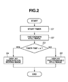
- Fig. 2 is a flow chart illustrating fluorescent photography according to an exemplary embodiment of the present invention.
- Fig. 3 is a chart illustrating a method for controlling the display at the initial fluorescence stage according to a first exemplary embodiment of the present invention.
- Fig. 4 is a chart illustrating a method for controlling the display at the later fluorescence stage according to the first exemplary embodiment.
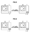
- Fig. 5 is a chart illustrating a method for controlling the display at the initial fluorescence stage according to a second exemplary embodiment of the present invention.
- Fig. 6 is a chart illustrating a method for controlling the display at the later fluorescence stage according to the second exemplary embodiment.
- Fig. 1 is a block diagram illustrating a configuration of an ophthalmological photographic apparatus according to a first exemplary embodiment of the present invention.
- the outputs of a still-image photographic unit 1 and an observation moving-image photographic unit 2 are connected to a display content control unit 4 via an image storage unit 3.
- a fluorescence stage determination unit 5 and an image display unit 6 are connected to the display content control unit 4.
- Both a still image of a subject's eye photographed by the still-image photographic unit 1 and an observation moving image of the subject's eye photographed by the observation moving-image photographic unit 2 are stored in the image storage unit 3.
- observation moving image
- the display content control unit 4 acquires the observation moving image or the still image from the image storage unit 3 to display it on the image display unit 6 and determines whether the current fluorescence stage is the initial fluorescence stage or later fluorescence stage via the fluorescence stage determination unit 5.
- Fig. 2 is a flow chart illustrating fluorescent photography according to the first exemplary embodiment.
- a fluorescent photographic mode is selected by an operator switching a photographic mode-changing switch (not shown) to start the fluorescent photography.
- a timer incorporated in the fluorescence stage determination unit 5 starts timing. The timing may be started by the operator pressing a timer start switch (not shown) or automatically started at an arbitrary or predetermined timing.
- the operator observes a change in the fluorescent agent while observing the observation moving image of a subject's fundus displayed on the image display unit 6 and also adjusts alignment for photographing a still image. After the alignment has been finished, then in step S2, the operator operates a switch (not shown) to photograph a still image, so that the still image data obtained by the still image photographic unit 1 is stored in the image storage unit 3.
- the image storage unit 3 may be a volatile or a nonvolatile storage device.
- step S3 the timer incorporated in the fluorescence stage determination unit 5 indicates whether a predetermined time "a" has elapsed. For example, if the predetermined time “a” is set to 10 minutes, the fluorescence stage determination unit 5 determines, using its timer, that the fluorescence stage has changed to the later fluorescence stage after 10 minutes have elapsed. If the predetermined time "a” has not yet elapsed (i.e. the present time is less than "a,” depicted as YES in step S3), the process proceeds to step S4. In step S4, the display content control unit 4 displays an observation moving image on the image display unit 6. If the predetermined time "a” has elapsed (i.e. the present time is greater than "a,” depicted as NO in step S3), the process proceeds to step S5. In step S5, the display content control unit 4 displays a still image on the image display unit 6.
- Fig. 3 is a chart illustrating a method for controlling the image display unit 6 at the initial fluorescence stage according to the first exemplary embodiment.
- the still-image data photographed by the still-image photographic unit 1 is stored in the image storage unit 3.
- the display content control unit 4 continues to acquire the observation moving-image data photographed by the observation moving-image photographic unit 2 from the image storage unit 3 to display an observation moving image M1' on the image display unit 6.
- Fig. 4 is a chart illustrating a method for controlling the image display unit 6 at the later fluorescence stage according to the first exemplary embodiment.
- the observation moving-image data photographed by the observation moving-image photographic unit 2 is stored in the image storage unit 3 before the still-image is photographed and the display content control unit 4 acquires the observation moving-image data from the image storage unit 3 to display the observation moving image M1 on the image display unit 6.
- a change in a state where the fluorescent agent flows is small at the later fluorescence stage during which the fluorescent agent is delivered throughout the veins, so that the operator does not need to continue with the continuous photography. Specifically, the operator may take photographs at an interval of 5 to 10 minutes, for example.
- the operator may photograph a still image while the fluorescence stage determination unit 5 determines that the fluorescence stage has changed to the later fluorescence stage.
- the display content control unit 4 acquires the observation still image photographed by the still-image photographic unit 1 from the image storage unit 3 to display a still image P1 on the image display unit 6. This enables the operator to confirm the still image P1 immediately after photographing to instantly determine whether re-photographing is needed.
- Fig. 5 is a chart illustrating a method for controlling the image display unit 6 at the initial fluorescence stage according to a second exemplary embodiment of the present invention.
- the display content control unit 4 acquires the observation moving-image data from the image storage unit 3 to display an observation moving image M2 in a large display window on the image display unit 6. If no single still image is photographed, an empty display frame or window 11 smaller than the observation moving image M2 is displayed on the lower right corner of the image display unit 6.
- the operator observes a change in the fluorescent agent while observing the observation moving image M2 of the subject's fundus and also adjusts alignment for photographing a still image at the time of observing the moving image to perform the operation for photographing the still image.
- the display content control unit 4 acquires both the observation moving-image data photographed by the observation moving-image photographic unit 2 and the still-image data photographed by the still-image photographic unit 1 from the image storage unit 3 to display both an observation moving image M2' and a still image P2 on the image display unit 6.
- displaying the observation moving image M2' made larger than the still image P2 allows the operator to concentrate on the observation and the photographing of the fundus image at the initial fluorescence stage and to simply confirm the photographed image at the same time.
- Fig. 6 is a chart illustrating a method for controlling the image display unit 6 at the later fluorescence stage according to the second exemplary embodiment.
- the observation moving-image data photographed by the observation moving-image photographic unit 2 before the still image is photographed is stored in the image storage unit 3.
- the display content control unit 4 acquires both the observation moving-image data and the latest (or most recently photographed) still-image data photographed by the still-image photographic unit 1 from the image storage unit 3 to display the observation moving image M2 made larger than the still image P2 on the image display unit 6.
- the display content control unit 4 acquires both the observation moving-image data photographed by the observation moving-image photographic unit 2 and the still-image data photographed by the still-image photographic unit 1 from the image storage unit 3 to display both the observation moving image M2' and a still image P2' on the image display unit 6.
- displaying the still image P2' in a larger display window than the observation moving image M2' (which is displayed on the smaller display window 11) allows the operator to confirm a still image immediately after photographing and to continue a simple observation at the same time.
- the timer is incorporated in the fluorescence stage determination unit 5, and based on the output of the timer, it is determined whether the initial fluorescence stage has changed to the later fluorescence stage. However, it may be determined whether the initial fluorescence stage has changed to the later fluorescence stage by using an optical sensor (not shown) for detecting that the amount of fluorescent light from the subject's fundus is less than a predetermined reference value.
- observation and photograph may be performed by a single photographic apparatus.
Landscapes
- Health & Medical Sciences (AREA)
- Life Sciences & Earth Sciences (AREA)
- Engineering & Computer Science (AREA)
- Molecular Biology (AREA)
- Animal Behavior & Ethology (AREA)
- Biophysics (AREA)
- Ophthalmology & Optometry (AREA)
- Biomedical Technology (AREA)
- Heart & Thoracic Surgery (AREA)
- Medical Informatics (AREA)
- Veterinary Medicine (AREA)
- Surgery (AREA)
- Physics & Mathematics (AREA)
- General Health & Medical Sciences (AREA)
- Public Health (AREA)
- Multimedia (AREA)
- Hematology (AREA)
- Nuclear Medicine, Radiotherapy & Molecular Imaging (AREA)
- Radiology & Medical Imaging (AREA)
- Vascular Medicine (AREA)
- Eye Examination Apparatus (AREA)
Abstract
An ophthalmological photographic apparatus includes an observation moving-image photographing unit (2) configured to photograph an observation moving image of a subject's eye, a still-image photographic unit (1) configured to photograph a still image of the subject's eye, an image display unit (6) configured to display at least one of the observation moving image and the still image, and a display content control unit (4) configured to cause the image display unit to display one of the observation moving image and the still image when the still-image photographic unit photographs a still image.
Description
- The present invention relates to an ophthalmological photographic apparatus for performing ophthalmological fluorescent photography.
- Until now, there has been known an ophthalmological photographic apparatus in which a subject is intravenously injected with a fluorescent agent to cause illumination light to excite the fluorescent agent in the vein to perform fluorescent photography on a subject's fundus. The amount of the fluorescent agent flowing into the vein of the fundus suddenly increases at a specific period of time after the fluorescent agent was intravenously injected and then gradually decreases. At an initial fluorescence stage immediately after the fluorescent agent was intravenously injected, the fluorescent agent first flows into a thick blood vessel and then flows into narrower capillary vessels, so that the flowing state of the fluorescent agent (along with the blood of the subject) drastically changes.
- In fluorescent photography, it is important to observe this change in detail. Japanese Patent Application Laid-Open No.
2003-230540 - In a later fluorescence stage in which a further period of time has passed after the fluorescent agent was intravenously injected, the fluorescent agent is delivered throughout the veins, so that a flowing state does not change so much. For this reason, in the later fluorescence stage, a change is small in the flowing state, so that continuous photographing is not necessary and observation is not very important either.
- Still images to be photographed may be few in number in the later fluorescence stage, thus allowing an immediate determination of whether the photography is successful and a resulting efficient balance between a manageable number of photographs and obtaining the required information in the photographs.
- However, it is difficult to determine whether the current stage is the initial fluorescence stage or later fluorescence stage at the time of photographing a still image, so that the fluorescent photography cannot be smoothly timed.
- It is desired to provide an ophthalmological photographic apparatus capable of efficiently performing photography by switching the contents displayed on an image display unit depending on the fluorescence stages of a fluorescent agent injected in the person being photographed.
- According to an aspect of the present invention, there is provided an ophthalmological photographic apparatus as specified in
claims 1 to 7. According to a second aspect of the invention, there is provided an ophthalmological photographic method as specified in claims 8 to 10. - Further features and aspects of the present invention will become apparent from the following detailed description of exemplary embodiments with reference to the attached drawings.
- The accompanying drawings, which are incorporated in and constitute a part of the specification, illustrate non-limitative exemplary embodiments, features, and aspects of the invention and, together with the description, serve to explain the principles of the invention.
-
Fig. 1 is a block diagram illustrating a configuration of an ophthalmological photographic apparatus according to an exemplary embodiment of the present invention. -
Fig. 2 is a flow chart illustrating fluorescent photography according to an exemplary embodiment of the present invention. -
Fig. 3 is a chart illustrating a method for controlling the display at the initial fluorescence stage according to a first exemplary embodiment of the present invention. -
Fig. 4 is a chart illustrating a method for controlling the display at the later fluorescence stage according to the first exemplary embodiment. -
Fig. 5 is a chart illustrating a method for controlling the display at the initial fluorescence stage according to a second exemplary embodiment of the present invention. -
Fig. 6 is a chart illustrating a method for controlling the display at the later fluorescence stage according to the second exemplary embodiment. - Various exemplary embodiments, features, and aspects of the invention will be described in detail below with reference to the drawings.
-
Fig. 1 is a block diagram illustrating a configuration of an ophthalmological photographic apparatus according to a first exemplary embodiment of the present invention. The outputs of a still-imagephotographic unit 1 and an observation moving-imagephotographic unit 2 are connected to a displaycontent control unit 4 via animage storage unit 3. A fluorescencestage determination unit 5 and animage display unit 6 are connected to the displaycontent control unit 4. - Both a still image of a subject's eye photographed by the still-image
photographic unit 1 and an observation moving image of the subject's eye photographed by the observation moving-imagephotographic unit 2 are stored in theimage storage unit 3. By "observation" moving image, it is understood that the moving image may be observed by an operator in real-time. Alternatively or additionally, the moving-image data may be stored and observed with a delay or at a later date. The displaycontent control unit 4 acquires the observation moving image or the still image from theimage storage unit 3 to display it on theimage display unit 6 and determines whether the current fluorescence stage is the initial fluorescence stage or later fluorescence stage via the fluorescencestage determination unit 5. -
Fig. 2 is a flow chart illustrating fluorescent photography according to the first exemplary embodiment. At first, a fluorescent photographic mode is selected by an operator switching a photographic mode-changing switch (not shown) to start the fluorescent photography. In step S1, a timer incorporated in the fluorescencestage determination unit 5 starts timing. The timing may be started by the operator pressing a timer start switch (not shown) or automatically started at an arbitrary or predetermined timing. - The operator observes a change in the fluorescent agent while observing the observation moving image of a subject's fundus displayed on the
image display unit 6 and also adjusts alignment for photographing a still image. After the alignment has been finished, then in step S2, the operator operates a switch (not shown) to photograph a still image, so that the still image data obtained by the still imagephotographic unit 1 is stored in theimage storage unit 3. Theimage storage unit 3 may be a volatile or a nonvolatile storage device. - Since a change in a state where the fluorescent agent flows into the blood vessels is drastic at the initial fluorescence stage immediately after the fluorescent agent is intravenously injected, the operator needs to photograph a large number of still images within a short time while observing a change in the fluorescent agent.
- In step S3, the timer incorporated in the fluorescence
stage determination unit 5 indicates whether a predetermined time "a" has elapsed. For example, if the predetermined time "a" is set to 10 minutes, the fluorescencestage determination unit 5 determines, using its timer, that the fluorescence stage has changed to the later fluorescence stage after 10 minutes have elapsed. If the predetermined time "a" has not yet elapsed (i.e. the present time is less than "a," depicted as YES in step S3), the process proceeds to step S4. In step S4, the displaycontent control unit 4 displays an observation moving image on theimage display unit 6. If the predetermined time "a" has elapsed (i.e. the present time is greater than "a," depicted as NO in step S3), the process proceeds to step S5. In step S5, the displaycontent control unit 4 displays a still image on theimage display unit 6. -
Fig. 3 is a chart illustrating a method for controlling theimage display unit 6 at the initial fluorescence stage according to the first exemplary embodiment. When the fluorescent photography is started, the observation moving-image data photographed by the observation moving-imagephotographic unit 2 is stored in theimage storage unit 3. The displaycontent control unit 4 acquires the observation moving-image data from theimage storage unit 3 to display an observation moving image M1 on theimage display unit 6. - If the operator photographs a still image during the initial fluorescence stage determined, the still-image data photographed by the still-image
photographic unit 1 is stored in theimage storage unit 3. The displaycontent control unit 4 continues to acquire the observation moving-image data photographed by the observation moving-imagephotographic unit 2 from theimage storage unit 3 to display an observation moving image M1' on theimage display unit 6. - This enables the operator to continue to observe a state where the fluorescent agent flows using the observation moving image M1' even immediately after the still image was photographed and to concentrate on the operation of photographing the following still image, thus allowing continuous photography over a short time.
-
Fig. 4 is a chart illustrating a method for controlling theimage display unit 6 at the later fluorescence stage according to the first exemplary embodiment. The observation moving-image data photographed by the observation moving-imagephotographic unit 2 is stored in theimage storage unit 3 before the still-image is photographed and the displaycontent control unit 4 acquires the observation moving-image data from theimage storage unit 3 to display the observation moving image M1 on theimage display unit 6. - A change in a state where the fluorescent agent flows is small at the later fluorescence stage during which the fluorescent agent is delivered throughout the veins, so that the operator does not need to continue with the continuous photography. Specifically, the operator may take photographs at an interval of 5 to 10 minutes, for example.
- The operator may photograph a still image while the fluorescence
stage determination unit 5 determines that the fluorescence stage has changed to the later fluorescence stage. In this case, the displaycontent control unit 4 acquires the observation still image photographed by the still-imagephotographic unit 1 from theimage storage unit 3 to display a still image P1 on theimage display unit 6. This enables the operator to confirm the still image P1 immediately after photographing to instantly determine whether re-photographing is needed. -
Fig. 5 is a chart illustrating a method for controlling theimage display unit 6 at the initial fluorescence stage according to a second exemplary embodiment of the present invention. When the fluorescent photography is started, the observation moving-image data photographed by the observation moving-imagephotographic unit 2 is stored in theimage storage unit 3. The displaycontent control unit 4 acquires the observation moving-image data from theimage storage unit 3 to display an observation moving image M2 in a large display window on theimage display unit 6. If no single still image is photographed, an empty display frame orwindow 11 smaller than the observation moving image M2 is displayed on the lower right corner of theimage display unit 6. The operator observes a change in the fluorescent agent while observing the observation moving image M2 of the subject's fundus and also adjusts alignment for photographing a still image at the time of observing the moving image to perform the operation for photographing the still image. - When the operator photographs a still image at the initial fluorescence stage, the display
content control unit 4 acquires both the observation moving-image data photographed by the observation moving-imagephotographic unit 2 and the still-image data photographed by the still-imagephotographic unit 1 from theimage storage unit 3 to display both an observation moving image M2' and a still image P2 on theimage display unit 6. At this point, displaying the observation moving image M2' made larger than the still image P2 allows the operator to concentrate on the observation and the photographing of the fundus image at the initial fluorescence stage and to simply confirm the photographed image at the same time. -
Fig. 6 is a chart illustrating a method for controlling theimage display unit 6 at the later fluorescence stage according to the second exemplary embodiment. The observation moving-image data photographed by the observation moving-imagephotographic unit 2 before the still image is photographed is stored in theimage storage unit 3. The displaycontent control unit 4 acquires both the observation moving-image data and the latest (or most recently photographed) still-image data photographed by the still-imagephotographic unit 1 from theimage storage unit 3 to display the observation moving image M2 made larger than the still image P2 on theimage display unit 6. - When the operator photographs a still image at the later fluorescence stage, the display
content control unit 4 acquires both the observation moving-image data photographed by the observation moving-imagephotographic unit 2 and the still-image data photographed by the still-imagephotographic unit 1 from theimage storage unit 3 to display both the observation moving image M2' and a still image P2' on theimage display unit 6. At this point, displaying the still image P2' in a larger display window than the observation moving image M2' (which is displayed on the smaller display window 11) allows the operator to confirm a still image immediately after photographing and to continue a simple observation at the same time. - In the first and second exemplary embodiments described above, the timer is incorporated in the fluorescence
stage determination unit 5, and based on the output of the timer, it is determined whether the initial fluorescence stage has changed to the later fluorescence stage. However, it may be determined whether the initial fluorescence stage has changed to the later fluorescence stage by using an optical sensor (not shown) for detecting that the amount of fluorescent light from the subject's fundus is less than a predetermined reference value. - The above exemplary embodiments are described using the still-image photographic unit and the observation moving-image photographic unit, which are different from each other. However, observation and photograph may be performed by a single photographic apparatus.
- While the present invention has been described with reference to exemplary embodiments, it is to be understood that the invention is not limited to the disclosed exemplary embodiments. The scope of the following claims is to be accorded the broadest interpretation so as to encompass all modifications, equivalent structures, and functions.
Claims (10)
- An ophthalmological photographic apparatus comprising:a moving-image photographic unit (2) configured to record a moving image of a subject's eye;a still-image photographic unit (1) configured to photograph a still image of the subject's eye;an image display unit (6) configured to display at least one of the moving image and the still image; anda display content control unit (4) configured to cause the image display unit (6) to display at least one of the moving image (M1) and the still image (P1) when the still-image photographic unit (1) photographs a still image.
- An ophthalmological photographic apparatus according to claim 1, further comprising a fluorescence stage determination unit (5) configured to determine whether a fluorescent agent injected into the subject is in an initial fluorescence stage or a later fluorescence stage,
wherein the display content control unit (4) is configured to cause the image display unit (6) to display the moving image (M1') if the still image is photographed during the initial fluorescence stage, and to display the still image (P1) if the still image is photographed during the later fluorescence stage. - An ophthalmological photographic apparatus according to claim 1, further comprising:a fluorescence stage determination unit (5) configured to determine whether a fluorescent agent injected into the subject is in an initial fluorescence stage or a later fluorescence stage, whereinthe image display unit (6) is configured to display the moving image (M2) in a first display window before the still image is photographed; andthe display content control unit (4) is configured:when the still-image photographic unit photographs a still image during the initial fluorescence stage, to cause the image display unit to continue to display the moving image (M2')in the first display window and to display the still image (P2) in a second display window (11) smaller than the first display window ; andwhen the still-image photographic unit photographs a still image during the later fluorescence stage, to cause the image display unit(6) to display the still image (P2') in the first display window and the moving image (M2') in the second display window (11).
- An ophthalmological photographic apparatus according to claim 3, wherein, during the later fluorescence stage, a most recently photographed still image (P2) is displayed in the second display window (11) until a still image (P2') is photographed.
- An ophthalmological photographic apparatus according to claim 2, 3 or 4, wherein the fluorescence stage determination unit (5) comprises a timer for indicating when a time (a) has lapsed corresponding to the initial fluorescence stage.
- An ophthalmological photographic apparatus according to claim 2, 3 or 4, wherein the fluorescence stage determination unit (5) comprises an optical sensor for sensing fluorescence in the subject's eye and determining when the initial fluorescence stage is ending and the later fluorescence stage is beginning based on a change in the sensed fluorescence.
- An ophthalmological photographic apparatus according to any preceding claim, wherein the moving image comprises real-time image data.
- An ophthalmological photographic method comprising the steps of:recording a moving image (M1) of an eye of a subject that has been injected with a fluorescent agent;photographing a still image (P1) of the eye of the subject;determining whether the fluorescent agent is in an initial fluorescence stage or a later fluorescence stage; anddisplaying at least one of the moving image (M1) and the still image (P1) in dependence on the result of the determination step.
- An ophthalmological photographic method according to claim 8, wherein,
if the fluorescent agent is in the initial fluorescence stage when the still image (P1) is photographed, only the moving image (M1') is displayed; and
if the fluorescent agent is in the later fluorescence stage when the still image is photographed, the still image (P1) is displayed once the photographing step is taken. - An ophthalmological photographic method according to claim 8, wherein,
if the fluorescent agent is in the initial fluorescence stage when the still image (P2) is photographed, the moving image (M2') is displayed in a first display window and the still image (P2) is displayed in a second window (11) smaller than the first display window; and
if the fluorescent agent is in the later fluorescence stage when the still image is photographed, the moving image (M2) is displayed in the first display window until the still image is photographed, and then the still image (P2') is displayed in the first display window and the moving image (M2') is displayed in the second window (11).
Applications Claiming Priority (1)
| Application Number | Priority Date | Filing Date | Title |
|---|---|---|---|
| JP2008269958A JP4669892B2 (en) | 2008-10-20 | 2008-10-20 | Ophthalmic imaging equipment |
Publications (1)
| Publication Number | Publication Date |
|---|---|
| EP2177152A1 true EP2177152A1 (en) | 2010-04-21 |
Family
ID=41404075
Family Applications (1)
| Application Number | Title | Priority Date | Filing Date |
|---|---|---|---|
| EP09173410A Withdrawn EP2177152A1 (en) | 2008-10-20 | 2009-10-19 | Ophthalmological photographic apparatus |
Country Status (3)
| Country | Link |
|---|---|
| US (2) | US7914146B2 (en) |
| EP (1) | EP2177152A1 (en) |
| JP (1) | JP4669892B2 (en) |
Families Citing this family (1)
| Publication number | Priority date | Publication date | Assignee | Title |
|---|---|---|---|---|
| EP2633804B1 (en) * | 2012-03-02 | 2017-12-06 | Nidek Co., Ltd | Ophthalmologic photographing apparatus |
Citations (6)
| Publication number | Priority date | Publication date | Assignee | Title |
|---|---|---|---|---|
| JPH11267104A (en) * | 1998-03-20 | 1999-10-05 | Canon Inc | Fundus camera |
| JP2000316812A (en) * | 1999-05-07 | 2000-11-21 | Topcon Corp | Ophthalmic imaging equipment |
| US6456787B1 (en) * | 1999-11-26 | 2002-09-24 | Canon Kabushiki Kaisha | Eye fundus camera |
| JP2003230540A (en) | 2002-02-08 | 2003-08-19 | Canon Inc | Ophthalmic imaging equipment |
| US20060028617A1 (en) * | 2004-08-09 | 2006-02-09 | Kazunori Matsumura | Ophthalmic photographic apparatus |
| JP2006158864A (en) * | 2004-12-10 | 2006-06-22 | Canon Inc | Ophthalmic imaging equipment |
Family Cites Families (3)
| Publication number | Priority date | Publication date | Assignee | Title |
|---|---|---|---|---|
| JP2000296113A (en) * | 1999-04-15 | 2000-10-24 | Canon Inc | Fundus camera |
| JP2000296114A (en) * | 1999-04-15 | 2000-10-24 | Canon Inc | Eye photographing device |
| JP3892390B2 (en) * | 2002-12-04 | 2007-03-14 | 株式会社トプコン | Optometry equipment |
-
2008
- 2008-10-20 JP JP2008269958A patent/JP4669892B2/en not_active Expired - Fee Related
-
2009
- 2009-10-19 US US12/581,777 patent/US7914146B2/en not_active Expired - Fee Related
- 2009-10-19 EP EP09173410A patent/EP2177152A1/en not_active Withdrawn
-
2011
- 2011-02-25 US US13/035,878 patent/US8465152B2/en not_active Expired - Fee Related
Patent Citations (6)
| Publication number | Priority date | Publication date | Assignee | Title |
|---|---|---|---|---|
| JPH11267104A (en) * | 1998-03-20 | 1999-10-05 | Canon Inc | Fundus camera |
| JP2000316812A (en) * | 1999-05-07 | 2000-11-21 | Topcon Corp | Ophthalmic imaging equipment |
| US6456787B1 (en) * | 1999-11-26 | 2002-09-24 | Canon Kabushiki Kaisha | Eye fundus camera |
| JP2003230540A (en) | 2002-02-08 | 2003-08-19 | Canon Inc | Ophthalmic imaging equipment |
| US20060028617A1 (en) * | 2004-08-09 | 2006-02-09 | Kazunori Matsumura | Ophthalmic photographic apparatus |
| JP2006158864A (en) * | 2004-12-10 | 2006-06-22 | Canon Inc | Ophthalmic imaging equipment |
Also Published As
| Publication number | Publication date |
|---|---|
| US20100097575A1 (en) | 2010-04-22 |
| US7914146B2 (en) | 2011-03-29 |
| US8465152B2 (en) | 2013-06-18 |
| JP4669892B2 (en) | 2011-04-13 |
| US20110149244A1 (en) | 2011-06-23 |
| JP2010094433A (en) | 2010-04-30 |
Similar Documents
| Publication | Publication Date | Title |
|---|---|---|
| CN102483559B (en) | photography device | |
| TW201102938A (en) | Image capturing apparatus, face area detecting method and program recording medium | |
| US8503856B2 (en) | Imaging apparatus and control method for the same, shooting control apparatus, and shooting control method | |
| CN1311779C (en) | Ophthalmological apparatus | |
| US7914146B2 (en) | Ophthalmological photographic apparatus | |
| EP1396225B1 (en) | Ophthalmic imaging apparatus | |
| JP4136559B2 (en) | Ophthalmic imaging equipment | |
| JP4437664B2 (en) | Fundus camera | |
| JP3987760B2 (en) | Ophthalmic examination equipment | |
| JP2000333906A (en) | Ophthalmic imaging equipment | |
| JP4754945B2 (en) | Ophthalmic imaging equipment | |
| JP2024004880A (en) | Photography support device, imaging device, and method of controlling the imaging device | |
| JP5094233B2 (en) | Ophthalmic photographing apparatus and ophthalmic photographing system | |
| JP2002034923A (en) | Ophthalmic imaging equipment | |
| JP2002077711A (en) | Imaging device | |
| JP5587481B2 (en) | Ophthalmic photographing apparatus, information processing apparatus, and control method | |
| JP2003010133A (en) | Ophthalmic imaging equipment | |
| JP3154799B2 (en) | Imaging equipment | |
| JP5389220B2 (en) | Ophthalmic imaging equipment | |
| JPH0651387A (en) | camera | |
| JPH04197337A (en) | Photographing device for ophthalmology | |
| JP3382732B2 (en) | Finder device | |
| JP2014236246A (en) | Imaging apparatus | |
| JP2021021805A (en) | Imaging device | |
| JPH04282130A (en) | Ophthalmic photographing device |
Legal Events
| Date | Code | Title | Description |
|---|---|---|---|
| PUAI | Public reference made under article 153(3) epc to a published international application that has entered the european phase |
Free format text: ORIGINAL CODE: 0009012 |
|
| AK | Designated contracting states |
Kind code of ref document: A1 Designated state(s): AT BE BG CH CY CZ DE DK EE ES FI FR GB GR HR HU IE IS IT LI LT LU LV MC MK MT NL NO PL PT RO SE SI SK SM TR |
|
| AX | Request for extension of the european patent |
Extension state: AL BA RS |
|
| 17P | Request for examination filed |
Effective date: 20101021 |
|
| STAA | Information on the status of an ep patent application or granted ep patent |
Free format text: STATUS: THE APPLICATION HAS BEEN WITHDRAWN |
|
| 18W | Application withdrawn |
Effective date: 20161014 |