EP2177151A1 - Opthalmologic photographing apparatus - Google Patents
Opthalmologic photographing apparatus Download PDFInfo
- Publication number
- EP2177151A1 EP2177151A1 EP09173408A EP09173408A EP2177151A1 EP 2177151 A1 EP2177151 A1 EP 2177151A1 EP 09173408 A EP09173408 A EP 09173408A EP 09173408 A EP09173408 A EP 09173408A EP 2177151 A1 EP2177151 A1 EP 2177151A1
- Authority
- EP
- European Patent Office
- Prior art keywords
- observation
- eye
- examination
- switching
- examined
- Prior art date
- Legal status (The legal status is an assumption and is not a legal conclusion. Google has not performed a legal analysis and makes no representation as to the accuracy of the status listed.)
- Withdrawn
Links
Images


Classifications
-
- A—HUMAN NECESSITIES
- A61—MEDICAL OR VETERINARY SCIENCE; HYGIENE
- A61B—DIAGNOSIS; SURGERY; IDENTIFICATION
- A61B3/00—Apparatus for testing the eyes; Instruments for examining the eyes
- A61B3/10—Objective types, i.e. instruments for examining the eyes independent of the patients' perceptions or reactions
- A61B3/12—Objective types, i.e. instruments for examining the eyes independent of the patients' perceptions or reactions for looking at the eye fundus, e.g. ophthalmoscopes
-
- A—HUMAN NECESSITIES
- A61—MEDICAL OR VETERINARY SCIENCE; HYGIENE
- A61B—DIAGNOSIS; SURGERY; IDENTIFICATION
- A61B3/00—Apparatus for testing the eyes; Instruments for examining the eyes
- A61B3/0091—Fixation targets for viewing direction
-
- A—HUMAN NECESSITIES
- A61—MEDICAL OR VETERINARY SCIENCE; HYGIENE
- A61B—DIAGNOSIS; SURGERY; IDENTIFICATION
- A61B3/00—Apparatus for testing the eyes; Instruments for examining the eyes
- A61B3/10—Objective types, i.e. instruments for examining the eyes independent of the patients' perceptions or reactions
- A61B3/14—Arrangements specially adapted for eye photography
- A61B3/145—Arrangements specially adapted for eye photography by video means
-
- A—HUMAN NECESSITIES
- A61—MEDICAL OR VETERINARY SCIENCE; HYGIENE
- A61B—DIAGNOSIS; SURGERY; IDENTIFICATION
- A61B3/00—Apparatus for testing the eyes; Instruments for examining the eyes
- A61B3/10—Objective types, i.e. instruments for examining the eyes independent of the patients' perceptions or reactions
- A61B3/14—Arrangements specially adapted for eye photography
- A61B3/15—Arrangements specially adapted for eye photography with means for aligning, spacing or blocking spurious reflection ; with means for relaxing
- A61B3/152—Arrangements specially adapted for eye photography with means for aligning, spacing or blocking spurious reflection ; with means for relaxing for aligning
Definitions
- the present invention relates to an ophthalmologic photographing apparatus that enables switching between an infrared light observation and a visible light observation.
- an eye fundus photography for capturing an image of a fundus of an eye to be examined includes a non-mydriatic photography for capturing (photographing) an image thereof without a mydriatic agent being instilled into the eye to be examined, and a mydriatic photography for capturing an image thereof with the mydriatic agent being instilled into the eye to be examined are known.
- the eye fundus photographing is performed by causing the eye to be in state of natural mydriasis in a dark place, and an observation is made using infrared light in order to prevent the pupil of the eye from narrowing (i.e., to prevent miosis) during an observation.
- the eye fundus photographing is performed in a state where the pupil of an eye to be examined is forcibly dilated by the mydriatic agent.
- the mydriatic photography since the miosis does not occur even if visible light is irradiated, an observation with visible light is generally performed. However, the observation may be conducted with infrared light in order to reduce burden to the eye to be examined.
- Japanese Patent Application Laid-Open No. 9-66030 discusses a combined machine that can perform both the non-mydriatic photographing and the mydriatic photographing.
- an examiner can switch the mode between the non-mydriatic photographing mode and the mydriatic photographing mode. Thereby the photographing is performed by switching the mode to the infrared light observation during the non-mydriatic photographing, and to the visible light observation during the mydriatic photographing.
- an examination time normally 10 to 30 minutes or longer.
- the amount of change of an observed image due to inflow of the fluorescent agent is large, a number of photographs need to be taken in a short time.
- a photographing interval is taken longer since the amount of change of the observed image is small.
- Japanese Patent Application Laid-Open No. 2004-180705 discusses an apparatus that can concurrently implement a plurality of examinations in order to handle such cases.
- an examiner may forget a mode switching from the visible light observation to the infrared light observation.
- an examiner may switch the mode to the visible light observation by an operational mistake.
- the pupil of the eye When visible light is irradiated to an eye of an examinee who has not undergone instillation of the mydriatic agent, the pupil of the eye may be narrowed. Once the pupil of the eye to be examined is narrowed, a waiting time until the pupil is open again may be needed, and photographing efficiency may be deteriorated.
- the present invention is directed to an ophthalmologic photographing apparatus that can prevent visible light from being irradiated on an eye to be examined into which a mydriatic agent has not been instilled, even when an examiner forgets to switch mode from a visible light observation to an infrared light observation, and prevent operational mistake of switching to the visible light observation.
- an ophthalmologic photographing apparatus as specified in claims 1 to 8.
- Fig.1 is a circuit block diagram of an ophthalmologic photographing apparatus according to a first exemplary embodiment of the present invention.
- Fig. 2 is a flowchart illustrating an operation of the ophthalmologic photographing apparatus according to the first exemplary embodiment of the present invention.
- Fig. 3 is a circuit block diagram according to a second exemplary embodiment of the present invention.
- Fig. 4 is a flowchart illustrating an operation of the ophthalmologic photographing apparatus according to the second exemplary embodiment of the present invention.
- Fig. 5 illustrates an input screen
- Fig. 6 is a circuit block diagram according to a third exemplary embodiment of the present invention.
- Fig. 7 is an example of a list of observation states.
- Fig. 8 is a flowchart illustrating an operation of the ophthalmologic photographing apparatus according to the third exemplary embodiment of the present invention.
- Fig. 9 is a circuit block diagram according to a fourth exemplary embodiment of the present invention.
- Fig. 10 illustrates an input screen.
- Fig. 11 is an example of a list of observation states.
- Fig. 12 is a flowchart illustrating an operation of the ophthalmologic photographing apparatus according to the fourth exemplary embodiment of the present invention.
- Fig. 1 illustrates a circuit block diagram of an ophthalmologic photographing apparatus according to a first exemplary embodiment.
- An infrared light observation unit 1 for observing an eye to be examined with infrared light and a visible light observation unit 2 for observing the eye to be examined with visible light are connected to an observation switching unit 3 that switches between the infrared light observation and the visible light observation.
- the observation switching unit may be a physical switch that switches between the infrared light observation unit and the visible light observation unit, or it may be a physical or software-implemented switch that causes either infrared or visible light to be emitted by, for example, a single emitter.
- the observation switching unit 3 is connected to a control unit 4.
- a photographing unit 6 that captures an image of the eye to be examined is connected to the control unit 4.
- a start and completion management unit 5 that manages the start of the examination and the completion of the examination may be connected to the control unit 4, alternatively, this information may be input by an examiner (e.g. an ophthalmologist carrying out the eye exam).
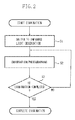
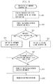
- Fig. 2 is a flowchart of a photographing operation using the ophthalmologic photographing apparatus according to the present exemplary embodiment.
- step S1 the control unit 4 selects the infrared light observation unit 1 according to the input from the observation switching unit 3.
- step S2 an examiner performs alignment while observing the eye to be examined, and takes photograph of the eye to be examined by the photographing unit 6.
- step S3 the start and completion management unit 5 determines whether the examination is completed according to a selection of an examination complete button (not illustrated), and repeats the process in step S2 until it is determined that the examination is completed.
- An "examination" of the eye may be considered to include at least one "observation" of the using the photographing unit and either infrared or visible light.
- the switching may be executed after it is determined that the examination has been completed in step S3, namely, at the time of completion of the examination.
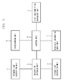
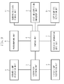
- Fig. 3 illustrates a circuit block diagram according to a second exemplary embodiment, and components or portions similar to those described in the first exemplary embodiment are denoted by the same reference numerals.
- a mydriasis information input unit 7 for inputting information about whether the mydriatic agent is instilled into the eye to be examined, is connected to the control unit 4.
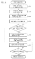
- Fig. 4 is a flowchart of a photographing operation according to the present second exemplary embodiment.
- the start and completion management unit 5 starts examination upon detecting a selection of an examination start button (not illustrated).
- the control unit 4 permits the observation switching unit 3 to switch between the observation units 1 and 2.
- the control unit 4 switches the observation state to the infrared light observation by the infrared light observation unit 1 via the observation switching unit 3.
- step S13 the control unit 4 prohibits the observation switching unit 3 from switching between the observation units 1 and 2.
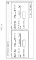
- step S14 an examiner inputs information about whether the mydriatic agent is instilled into the eye to be examined, for instance, using an input screen 5 of the mydriasis information input unit 7 illustrated in Fig. 5 via the mydriasis information input unit 7. Further, on the input screen 5, the examiner may input additional information such as type of mydriatic agent, diameter of pupil or the like.
- step S15 the control unit 4 determines whether the mydriatic agent is instilled into the eye, which has been input in step S14. If it is determined that the mydriatic agent is instilled into eye (YES in step S15), the processing proceeds to step S16, and the control unit 4 permits switching between the observation units 1 and 2 by the observation switching unit 3.
- step S17 the control unit 4 switches the observation state to the visible light observation by the visible light observation unit 2 via the observation switching unit 3, and subsequently in step S18, the examiner performs alignment while observing the eye to be examined, and takes photograph of the eye to be examined by the photographing unit 6.
- step S19 the start and completion management unit 5 determines whether the examination is completed, and repeats the process in step S18 until it is determined that the examination is completed (YES in step S19). Further, in step S15, if it is determined that the mydriatic agent is not instilled into eye (NO in step S15), the processing proceeds to step S18, and performs observation and photographing.
- control unit 4 permits switching between the observation units 1 and 2 of step S11 at the start of the examination, and switches the observation state to the infrared light observation in step S12, and prohibits switching between the observation units 1 and 2 of step S13.
- control unit 4 may perform these switching operations and switching prohibition after it is determined that the examination is completed in step S19, namely, at the completion of the examination. Further, the control unit 4 may perform these operations at the both times of the start of the examination and the completion of the examination. Furthermore, in step S17, although the control unit 4 has switched the observation from the infrared light observation to the visible light observation, the observation can be made with infrared light without switching the observation to the visible light observation.
- step S14 although information about whether the mydriatic agent is instilled into the eye is input via the mydriasis information input unit 7 after the start of the examination, it may be input before the start of the examination. In this case, whether the mydriatic agent is instilled into the eye is determined at the start of the examination. If the mydriatic agent is not instilled into the eye, the control unit 4 switches to the infrared light observation at the start of the examination, and prohibits switching between the observation units 1 and 2.
- control unit 4 permits switching to the infrared light observation or the visible light observation, and switching between the observation unit 1 and 2 thereafter, at the start of the examination.
- control unit 4 can control an internal fixation light which presents a fixation target from a photographic optical on-axis, and an external fixation light which presents the fixation target from a photographic optical off-axis as appropriate, in order to guide the eye to be examined in the following manner.
- control unit 4 turns off the internal fixation light and the external fixation light together at the start of the examination (if the lights are not already turned off). After the input of the mydriasis information, if it is determined that the mydriatic agent has not been instilled into the eye, the control unit 4 turns on the internal fixation light. If it is determined that the mydriatic agent has been instilled into the eye, the control unit 4 turns on the internal fixation light when switching to the infrared light observation, and turns on the external fixation light when switching to the visible light observation.
- Fig. 6 illustrates a circuit block diagram of an ophthalmologic photographing apparatus according to a third exemplary embodiment.
- an observation state storage unit 11 that stores observation state for each examination and multiple examination management units 12 that manages switching between examinations are connected to the control unit 4 for allowing a plurality of examinations to be implemented in parallel.
- Features in Fig. 6 of the third embodiment that may be the same as features of the first and second embodiments illustrated in Figs. 1 and 3 are denoted with the same reference numerals.
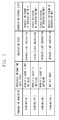
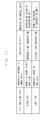
- Fig. 7 illustrates an example of a list of observation states, which is stored in the observation state storage unit 11.
- the observation state storage unit 11 stores "examination identifier”, "mydriasis information input state”, “observation unit”, and "observation control state” for all examinations to be implemented, as observation states.
- the observation state storage unit 11 stores input states such as "not yet input, " "mydriatic agent is not instilled, " “mydriatic agent is instilled” by the mydriasis information input unit 7.
- the observation state storage unit 11 stores whether the "observation state” is in a state of the infrared light observation or the visible light observation, and whether the "observation control state” is in a state of switching permission between the observation units 1 and 2, or switching prohibition between the observation units 1 and 2.
- Fig. 8 is a flowchart of a photographing operation in the present exemplary embodiment.
- step S21 the control unit 4 acquires an observation state of the "examination identifier" of switching destination (another eye being examined), from the observation state storage unit 11.
- step S22 the control unit 4 permits switching between the observation units 1 and 2 by the observation switching unit 3.
- step S23 the control unit 4 determines whether the observation state is an infrared light observation. If it is determined as the infrared light observation (YES in step S23), the processing proceeds to step S24.
- step S24 the control unit 4 switches the observation state to the infrared light observation by the observation switching unit 3, and then the processing proceeds to step S26.
- step S23 if it is determined that the visible light observation is performed (NO in step S23), the processing proceeds to step S25.
- step S25 the control unit 4 switches the observation state to the visible light observation by the observation switching unit 3, and the processing proceeds to step S26.
- step S26 the control unit 4 determines the "observation control state". If the "observation control state" is switching prohibition between the observation units 1 and 2, the processing proceeds to step S27. In step S27, the control unit 4 prohibits switching between the observation units 1 and 2 by the observation switching unit 3. In step S28, an examiner performs alignment while observing the eye to be examined, and photographs the eye to be examined by the photographing unit 6.
- step S26 if the "observation control state" is a switching permission between the observation units 1 and 2 (NO in step S26), the processing proceeds to step S28.
- the "mydriasis information input state" is stored in order to illustrate an example of the "observation state” and the “observation control state” according to the mydriasis information input state, the "mydriasis information input state” may not need to be stored.
- the present exemplary embodiment includes the mydriasis information input unit 7, and the control of switching permission, and prohibition between the "observation units” is performed is described, the controls of switching permission, and prohibition between the observation units 1 and 2 may not need to be performed in similar manner to the first exemplary embodiment. In this case, steps S22, S26, and S27 in the flowchart of Fig. 8 are unnecessary, and the "observation control state" illustrated in Fig. 7 may not need to be stored.
- Fig. 9 is a circuit block diagram according to a fourth exemplary embodiment.
- a left/right eye detection unit 21 is provided for detecting whether the eye to be examined is the left eye or the right eye, in place of the multiple examination management unit 12 according to the third exemplary embodiment.
- the rest of the reference numerals of Fig. 9 are the same as in Fig. 6 illustrating the third embodiment.
- Fig. 10 illustrates an input screen of the mydriasis information input unit 7 that can input whether the mydriatic agent is instilled for each of the left and right eyes.
- Fig. 11 illustrates an example of a list of observation states to be stored in the observation state storage unit 11, and the observation state storage unit 11 stores, "left or right eye”, "mydriasis information input state”, “observation state”, and "observation control state” as the observation states, for one examination under implementation.
- Input states (not yet input,” “mydriatic agent is not instilled, “ “mydriatic agent is instilled" obtained by the mydriasis information input unit 7 are stored in the "mydriasis information input state,” and whether the infrared light observation or the visible light observation is used is stored in the "observation state”. Which of the switching permission of the observation units 1 and 2, and the switching prohibition of the observation units 1 and 2 is selected, is stored in the "observation control state".
- Fig. 12 is a flowchart of a photographing operation in the present exemplary embodiment.
- step S31 the control unit 4 acquires observation state of the eye of the switching destination from the observation state storage unit 11.
- step S32 the control unit 4 permits switching between the observation units 1 and 2 by the observation switching unit 3.
- step S33 the control unit 4 determines whether the acquired "observation state" is an infrared light observation. If the acquired "observation state" is the infrared light observation (YES in step S33), the processing proceeds to step S34. In step S34, the control unit 4 switches the "observation state" to the infrared light observation by the observation switching unit 3, and the processing proceeds to step S36.
- step S33 if the "observation state" is a visible light observation (NO in step S33), the processing proceeds to step S35.
- step S35 the control unit 4 switches the observation state to the visible light observation by the observation switching unit 3, and the processing proceeds to step S36.
- step S36 the control unit 4 determines the "observation control state" acquired in steps S34 and S35. If the "observation control state" is the switching prohibition between the observation units 1 and 2 (YES in step S36), the processing proceeds to step S37. In step S37, the control unit 4 prohibits switching between the observation units 1 and 2 by the observation switching unit 3, and then in step S38, an examiner performs alignment while observing the eye to be examined, and photographs the eye to be examined by the photographing unit 6. In step S36, if the "observation control state" is the switching permission between the observation units 1 and 2 (NO in step S36), the processing proceeds to step S38.
- the "mydriasis information input state” is stored in order to illustrate an example of the "observation state", and the "observation control state" according to the mydriasis information input state, the "mydriasis information input state” may not need to be stored.
- the case including the mydriasis information input unit 7, and performing control of switching permission and prohibition of the observation units 1 and 2 is described above.
- the control of the switching permission and prohibition of the observation units 1 and 2 may not need to be performed in similar manner to the exemplary embodiment 1.
- the examination can be combined with the case of a plurality of examinations of the third exemplary embodiment.
- the control unit 4 automatically switches the observation state to the infrared light observation, at least at either one of the start of the examination or the completion of the examination.
- control unit 4 automatically switches the observation state to the infrared light observation as well as prohibits switching between the observation units, and permits switching between the observation units when the information is input that the mydriatic agent is instilled through the mydriasis information input. For this reason, if the infrared light observation is performed without the mydriatic agent being instilled into the eye, the miosis of the eye to be examined by operational mistake can be prevented.
Abstract
Upon detecting a selection of an examination start button, start and completion management means (5) starts an examination. The control means (4) switches an observation state to an infrared light observation by observation switching means (3). Next, an examiner performs alignment while observing an eye to be examined, and photographs the eye to be examined with a photographing means (6). The start and completion management means (5) determines whether the examination is completed according to a selection of an examination complete button, and repeats the alignment until it is determined that the examination is completed.
Description
- The present invention relates to an ophthalmologic photographing apparatus that enables switching between an infrared light observation and a visible light observation.
- Generally, an eye fundus photography for capturing an image of a fundus of an eye to be examined includes a non-mydriatic photography for capturing (photographing) an image thereof without a mydriatic agent being instilled into the eye to be examined, and a mydriatic photography for capturing an image thereof with the mydriatic agent being instilled into the eye to be examined are known. In the non-mydriatic photography, the eye fundus photographing is performed by causing the eye to be in state of natural mydriasis in a dark place, and an observation is made using infrared light in order to prevent the pupil of the eye from narrowing (i.e., to prevent miosis) during an observation.
- On the other hand, in the mydriatic photography, the eye fundus photographing is performed in a state where the pupil of an eye to be examined is forcibly dilated by the mydriatic agent. In the mydriatic photography, since the miosis does not occur even if visible light is irradiated, an observation with visible light is generally performed. However, the observation may be conducted with infrared light in order to reduce burden to the eye to be examined.
- Japanese Patent Application Laid-Open No.
9-66030 - Fluorescence photography in which the photographing is performed with the fluorescent agent being injected intravenously into the body of an examinee, requires an examination time of normally 10 to 30 minutes or longer. In general, during the initial stage of fluorescence in the fluorescence photography, since the amount of change of an observed image due to inflow of the fluorescent agent is large, a number of photographs need to be taken in a short time. However, during the later stage of the fluorescence in which the fluorescent agent has been circulated throughout the eye fundus, a photographing interval is taken longer since the amount of change of the observed image is small.
- In the fluorescence photography, when many examinees are photographed, another examinee may be sometimes photographed during the first examinee's photographing interval during the later stage of fluorescence, in order to enhance the overall photographing efficiency.
- Japanese Patent Application Laid-Open No.
2004-180705 - When visible light is irradiated to an eye of an examinee who has not undergone instillation of the mydriatic agent, the pupil of the eye may be narrowed. Once the pupil of the eye to be examined is narrowed, a waiting time until the pupil is open again may be needed, and photographing efficiency may be deteriorated.
- The present invention is directed to an ophthalmologic photographing apparatus that can prevent visible light from being irradiated on an eye to be examined into which a mydriatic agent has not been instilled, even when an examiner forgets to switch mode from a visible light observation to an infrared light observation, and prevent operational mistake of switching to the visible light observation.
- According to an aspect of the present invention, there is provided an ophthalmologic photographing apparatus as specified in
claims 1 to 8. - Further features and aspects of the present invention will become apparent from the following detailed description of exemplary embodiments with reference to the attached drawings.
- The accompanying drawings, which are incorporated in and constitute a part of the specification, illustrate exemplary embodiments, features, and aspects of the invention and, together with the description, serve to explain the principles of the invention.
-
Fig.1 is a circuit block diagram of an ophthalmologic photographing apparatus according to a first exemplary embodiment of the present invention. -
Fig. 2 is a flowchart illustrating an operation of the ophthalmologic photographing apparatus according to the first exemplary embodiment of the present invention. -
Fig. 3 is a circuit block diagram according to a second exemplary embodiment of the present invention. -
Fig. 4 is a flowchart illustrating an operation of the ophthalmologic photographing apparatus according to the second exemplary embodiment of the present invention. -
Fig. 5 illustrates an input screen. -
Fig. 6 is a circuit block diagram according to a third exemplary embodiment of the present invention. -
Fig. 7 is an example of a list of observation states. -
Fig. 8 is a flowchart illustrating an operation of the ophthalmologic photographing apparatus according to the third exemplary embodiment of the present invention. -
Fig. 9 is a circuit block diagram according to a fourth exemplary embodiment of the present invention. -
Fig. 10 illustrates an input screen. -
Fig. 11 is an example of a list of observation states. -
Fig. 12 is a flowchart illustrating an operation of the ophthalmologic photographing apparatus according to the fourth exemplary embodiment of the present invention. - Various exemplary embodiments, features, and aspects of the invention will be described in detail below with reference to the drawings.
-
Fig. 1 illustrates a circuit block diagram of an ophthalmologic photographing apparatus according to a first exemplary embodiment. An infraredlight observation unit 1 for observing an eye to be examined with infrared light and a visiblelight observation unit 2 for observing the eye to be examined with visible light are connected to anobservation switching unit 3 that switches between the infrared light observation and the visible light observation. In other words, the observation switching unit may be a physical switch that switches between the infrared light observation unit and the visible light observation unit, or it may be a physical or software-implemented switch that causes either infrared or visible light to be emitted by, for example, a single emitter. Theobservation switching unit 3 is connected to acontrol unit 4. A photographingunit 6 that captures an image of the eye to be examined is connected to thecontrol unit 4. A start andcompletion management unit 5 that manages the start of the examination and the completion of the examination may be connected to thecontrol unit 4, alternatively, this information may be input by an examiner (e.g. an ophthalmologist carrying out the eye exam). -
Fig. 2 is a flowchart of a photographing operation using the ophthalmologic photographing apparatus according to the present exemplary embodiment. - First, upon detecting a selection of an examination start button (not illustrated), the start and
completion management unit 5 starts the examination. In step S1, thecontrol unit 4 selects the infraredlight observation unit 1 according to the input from theobservation switching unit 3. - Then, in step S2, an examiner performs alignment while observing the eye to be examined, and takes photograph of the eye to be examined by the photographing
unit 6. In step S3, the start andcompletion management unit 5 determines whether the examination is completed according to a selection of an examination complete button (not illustrated), and repeats the process in step S2 until it is determined that the examination is completed. An "examination" of the eye may be considered to include at least one "observation" of the using the photographing unit and either infrared or visible light. - In the first exemplary embodiment, when the examination is started in step S1, although the
control unit 4 has switched the observation mode to the infrared light observation, the switching may be executed after it is determined that the examination has been completed in step S3, namely, at the time of completion of the examination. -
Fig. 3 illustrates a circuit block diagram according to a second exemplary embodiment, and components or portions similar to those described in the first exemplary embodiment are denoted by the same reference numerals. In the present second exemplary embodiment, a mydriasisinformation input unit 7 for inputting information about whether the mydriatic agent is instilled into the eye to be examined, is connected to thecontrol unit 4. -
Fig. 4 is a flowchart of a photographing operation according to the present second exemplary embodiment. - First, the start and
completion management unit 5 starts examination upon detecting a selection of an examination start button (not illustrated). In step S11, thecontrol unit 4 permits theobservation switching unit 3 to switch between theobservation units control unit 4 switches the observation state to the infrared light observation by the infraredlight observation unit 1 via theobservation switching unit 3. - Next, in step S13, the
control unit 4 prohibits theobservation switching unit 3 from switching between theobservation units input screen 5 of the mydriasisinformation input unit 7 illustrated inFig. 5 via the mydriasisinformation input unit 7. Further, on theinput screen 5, the examiner may input additional information such as type of mydriatic agent, diameter of pupil or the like. - Then, in step S15, the
control unit 4 determines whether the mydriatic agent is instilled into the eye, which has been input in step S14. If it is determined that the mydriatic agent is instilled into eye (YES in step S15), the processing proceeds to step S16, and thecontrol unit 4 permits switching between theobservation units observation switching unit 3. - Next, in step S17, the
control unit 4 switches the observation state to the visible light observation by the visiblelight observation unit 2 via theobservation switching unit 3, and subsequently in step S18, the examiner performs alignment while observing the eye to be examined, and takes photograph of the eye to be examined by the photographingunit 6. - Finally, in step S19, the start and
completion management unit 5 determines whether the examination is completed, and repeats the process in step S18 until it is determined that the examination is completed (YES in step S19). Further, in step S15, if it is determined that the mydriatic agent is not instilled into eye (NO in step S15), the processing proceeds to step S18, and performs observation and photographing. - In the present second exemplary embodiment, the
control unit 4 permits switching between theobservation units observation units - However, the
control unit 4 may perform these switching operations and switching prohibition after it is determined that the examination is completed in step S19, namely, at the completion of the examination. Further, thecontrol unit 4 may perform these operations at the both times of the start of the examination and the completion of the examination. Furthermore, in step S17, although thecontrol unit 4 has switched the observation from the infrared light observation to the visible light observation, the observation can be made with infrared light without switching the observation to the visible light observation. - Furthermore, in step S14, although information about whether the mydriatic agent is instilled into the eye is input via the mydriasis
information input unit 7 after the start of the examination, it may be input before the start of the examination. In this case, whether the mydriatic agent is instilled into the eye is determined at the start of the examination. If the mydriatic agent is not instilled into the eye, thecontrol unit 4 switches to the infrared light observation at the start of the examination, and prohibits switching between theobservation units - Further, if the mydriatic agent is instilled into the eye, the
control unit 4 permits switching to the infrared light observation or the visible light observation, and switching between theobservation unit - In the present exemplary embodiment, because observation and photographing are performed after the mydriasis information is input, the
control unit 4 can control an internal fixation light which presents a fixation target from a photographic optical on-axis, and an external fixation light which presents the fixation target from a photographic optical off-axis as appropriate, in order to guide the eye to be examined in the following manner. - That is, the
control unit 4 turns off the internal fixation light and the external fixation light together at the start of the examination (if the lights are not already turned off). After the input of the mydriasis information, if it is determined that the mydriatic agent has not been instilled into the eye, thecontrol unit 4 turns on the internal fixation light. If it is determined that the mydriatic agent has been instilled into the eye, thecontrol unit 4 turns on the internal fixation light when switching to the infrared light observation, and turns on the external fixation light when switching to the visible light observation. -
Fig. 6 illustrates a circuit block diagram of an ophthalmologic photographing apparatus according to a third exemplary embodiment. In the present exemplary embodiment, an observationstate storage unit 11 that stores observation state for each examination and multipleexamination management units 12 that manages switching between examinations are connected to thecontrol unit 4 for allowing a plurality of examinations to be implemented in parallel. Features inFig. 6 of the third embodiment that may be the same as features of the first and second embodiments illustrated inFigs. 1 and3 are denoted with the same reference numerals. -
Fig. 7 illustrates an example of a list of observation states, which is stored in the observationstate storage unit 11. The observationstate storage unit 11 stores "examination identifier", "mydriasis information input state", "observation unit", and "observation control state" for all examinations to be implemented, as observation states. - In the "mydriasis information input state", the observation
state storage unit 11 stores input states such as "not yet input, " "mydriatic agent is not instilled, " "mydriatic agent is instilled" by the mydriasisinformation input unit 7. The observationstate storage unit 11 stores whether the "observation state" is in a state of the infrared light observation or the visible light observation, and whether the "observation control state" is in a state of switching permission between theobservation units observation units -
Fig. 8 is a flowchart of a photographing operation in the present exemplary embodiment. - When the multiple
examination management unit 12 detects switching to another examination, in step S21, thecontrol unit 4 acquires an observation state of the "examination identifier" of switching destination (another eye being examined), from the observationstate storage unit 11. - Next in step S22, the
control unit 4 permits switching between theobservation units observation switching unit 3. In step S23, thecontrol unit 4 determines whether the observation state is an infrared light observation. If it is determined as the infrared light observation (YES in step S23), the processing proceeds to step S24. In step S24, thecontrol unit 4 switches the observation state to the infrared light observation by theobservation switching unit 3, and then the processing proceeds to step S26. Alternatively, in step S23, if it is determined that the visible light observation is performed (NO in step S23), the processing proceeds to step S25. In step S25, thecontrol unit 4 switches the observation state to the visible light observation by theobservation switching unit 3, and the processing proceeds to step S26. - Then, in step S26, the
control unit 4 determines the "observation control state". If the "observation control state" is switching prohibition between theobservation units control unit 4 prohibits switching between theobservation units observation switching unit 3. In step S28, an examiner performs alignment while observing the eye to be examined, and photographs the eye to be examined by the photographingunit 6. - In step S26, if the "observation control state" is a switching permission between the
observation units 1 and 2 (NO in step S26), the processing proceeds to step S28. - In the present exemplary embodiment, although the "mydriasis information input state" is stored in order to illustrate an example of the "observation state" and the "observation control state" according to the mydriasis information input state, the "mydriasis information input state" may not need to be stored.
- Although the present exemplary embodiment includes the mydriasis
information input unit 7, and the control of switching permission, and prohibition between the "observation units" is performed is described, the controls of switching permission, and prohibition between theobservation units Fig. 8 are unnecessary, and the "observation control state" illustrated inFig. 7 may not need to be stored. -
Fig. 9 is a circuit block diagram according to a fourth exemplary embodiment. In the present fourth exemplary embodiment, a left/righteye detection unit 21 is provided for detecting whether the eye to be examined is the left eye or the right eye, in place of the multipleexamination management unit 12 according to the third exemplary embodiment. The rest of the reference numerals ofFig. 9 are the same as inFig. 6 illustrating the third embodiment. -
Fig. 10 illustrates an input screen of the mydriasisinformation input unit 7 that can input whether the mydriatic agent is instilled for each of the left and right eyes.Fig. 11 illustrates an example of a list of observation states to be stored in the observationstate storage unit 11, and the observationstate storage unit 11 stores, "left or right eye", "mydriasis information input state", "observation state", and "observation control state" as the observation states, for one examination under implementation. - Input states ("not yet input," "mydriatic agent is not instilled, " "mydriatic agent is instilled") obtained by the mydriasis
information input unit 7 are stored in the "mydriasis information input state," and whether the infrared light observation or the visible light observation is used is stored in the "observation state". Which of the switching permission of theobservation units observation units -
Fig. 12 is a flowchart of a photographing operation in the present exemplary embodiment. - When the left/right
eye detection unit 21 detects switching between left and right eyes, then in step S31, thecontrol unit 4 acquires observation state of the eye of the switching destination from the observationstate storage unit 11. In step S32, thecontrol unit 4 permits switching between theobservation units observation switching unit 3. - Then, in step S33, the
control unit 4 determines whether the acquired "observation state" is an infrared light observation. If the acquired "observation state" is the infrared light observation (YES in step S33), the processing proceeds to step S34. In step S34, thecontrol unit 4 switches the "observation state" to the infrared light observation by theobservation switching unit 3, and the processing proceeds to step S36. - Further, in step S33, if the "observation state" is a visible light observation (NO in step S33), the processing proceeds to step S35. In step S35, the
control unit 4 switches the observation state to the visible light observation by theobservation switching unit 3, and the processing proceeds to step S36. - Then, in step S36, the
control unit 4 determines the "observation control state" acquired in steps S34 and S35. If the "observation control state" is the switching prohibition between theobservation units 1 and 2 (YES in step S36), the processing proceeds to step S37. In step S37, thecontrol unit 4 prohibits switching between theobservation units observation switching unit 3, and then in step S38, an examiner performs alignment while observing the eye to be examined, and photographs the eye to be examined by the photographingunit 6. In step S36, if the "observation control state" is the switching permission between theobservation units 1 and 2 (NO in step S36), the processing proceeds to step S38. - In the present exemplary embodiment, although the "mydriasis information input state" is stored in order to illustrate an example of the "observation state", and the "observation control state" according to the mydriasis information input state, the "mydriasis information input state" may not need to be stored.
- Further, the case including the mydriasis
information input unit 7, and performing control of switching permission and prohibition of theobservation units observation units exemplary embodiment 1. - In this case, in the flowchart of
Fig.12 , steps S32, S36, and S37 are unnecessary, and the "observation control state" ofFig. 11 may not need to bee stored. - Furthermore, in the present exemplary embodiment, although the case where an examination is under implementation is described, the examination can be combined with the case of a plurality of examinations of the third exemplary embodiment.
- According to an ophthalmologic photographing apparatus of the exemplary embodiments of the present invention, the
control unit 4 automatically switches the observation state to the infrared light observation, at least at either one of the start of the examination or the completion of the examination. As a result, if the infrared light observation is performed without the mydriatic agent being instilled into the eye to be examined, the miosis of the eye, which may occur due to a switching mistake between the observation units, can be prevented. - Further, at least at either one of the start of the examination or the completion of the examination, the
control unit 4 automatically switches the observation state to the infrared light observation as well as prohibits switching between the observation units, and permits switching between the observation units when the information is input that the mydriatic agent is instilled through the mydriasis information input. For this reason, if the infrared light observation is performed without the mydriatic agent being instilled into the eye, the miosis of the eye to be examined by operational mistake can be prevented. - While the present invention has been described with reference to exemplary embodiments, it is to be understood that the invention is not limited to the disclosed exemplary embodiments. The scope of the following claims is to be accorded the broadest interpretation so as to encompass all modifications, equivalent structures, and functions.
Claims (8)
- An ophthalmologic photographing apparatus for use in at least one eye examination, said examination comprising at least one eye observation, the ophthalmologic photographing apparatus comprising:infrared light observation means (1) configured to perform an observation of an eye to be examined by using infrared light;visible light observation means (2) configured to perform a visible light observation of the eye to be examined by using visible light;observation switching means (3) configured to switch an observation state between the infrared light observation and the visible light observation;photographing means configured (6) to capture an image of the eye to be examined during an observation; andcontrol means (4) configured to control the observation switching means such that the observation switching means switches the observation state from the visible light observation to the infrared light observation at at least one of a start of an eye observation and a completion of the observation.
- The ophthalmologic photographing apparatus according to claim 1, further comprising start and completion management means (5) configured to manage the start of the at least one observation and the completion of the at least one observation within each examination.
- The ophthalmologic photographing apparatus according to claim 1 or 2, further comprising mydriasis information input means (7) configured to input information indicating whether mydriatic agent is instilled into the eye to be examined, wherein the control means (4) is further configured to:cause the observation switching means (3) to switch the observation state to the infrared light observation; andpermit switching of the observation means if the mydriasis information input means inputs information indicating that mydriatic agent is instilled into the eye to be examined.
- The ophthalmologic photographing apparatus according to claim 3, wherein the mydriasis information input means (7) is configured to input information indicating whether the mydriatic agent is instilled into the eye to be examined for left and right eyes separately.
- The ophthalmologic photographing apparatus according to claim 4, wherein the control means (4) is configured to cause the observation switching means to switch the observation state to the visible light observation if the mydriasis information input means inputs information indicating that the mydriatic agent is instilled into the eye being examined.
- The ophthalmologic photographing apparatus according to claim 3, 4 or 5, further comprising:an internal fixation light configured to present a fixation target from a photographic optical on-axis; andan external fixation light configured to present the fixation target from a photographic optical off-axis, the internal fixation light and the external fixation light being arranged to guide the eye to be examined,
wherein, when the mydriasis information input means (7) inputs information indicating that the mydriatic agent is not instilled into the eye, the control means (4) is configured to turn on the internal fixation light, and
when the mydriasis information input means inputs information indicating that the mydriatic agent is instilled into eye, the control means is configured to:turn on the internal fixation light when causing the observation switching means to switch the observation state to the infrared light observation; andturn on the external fixation light when causing the observation switching means to switch the observation state to the visible light observation. - The ophthalmologic photographing apparatus according to any one of claims 1 to 6, wherein an eye examination for a specific eye comprises at least two observations in the same observation state, the ophthalmologic photographing apparatus further comprising:multiple examination management means (12) configured to implement a plurality of examinations in parallel, and manage switching of the observation states between the plurality of examinations; andobservation state storage means (11) configured to store information indicating whether the infrared light observation or the visible light observation is performed for each examination,
wherein, when the multiple examination management means detects switching between the examinations, the control means is configured to set the observation state of the examination based on the information stored in the observation state storage means. - The ophthalmologic photographing apparatus according to any one of claim 1 to 7, further comprising:left or right eye detection means (21) configured to detect whether the eye to be examined is a left eye or right eye; andobservation state storage means (11) configured to store information indicating whether the observation state is the infrared light observation or the visible light observation for left and right eyes separately,
wherein, when the left or right eye detection means detects switching between left and right eyes, the control means is configured to set the observation state of the eye to be examined based on the information stored in the observation state storage means.
Applications Claiming Priority (1)
| Application Number | Priority Date | Filing Date | Title |
|---|---|---|---|
| JP2008269957A JP4669891B2 (en) | 2008-10-20 | 2008-10-20 | Ophthalmic imaging equipment |
Publications (1)
| Publication Number | Publication Date |
|---|---|
| EP2177151A1 true EP2177151A1 (en) | 2010-04-21 |
Family
ID=41395446
Family Applications (1)
| Application Number | Title | Priority Date | Filing Date |
|---|---|---|---|
| EP09173408A Withdrawn EP2177151A1 (en) | 2008-10-20 | 2009-10-19 | Opthalmologic photographing apparatus |
Country Status (3)
| Country | Link |
|---|---|
| US (1) | US8057040B2 (en) |
| EP (1) | EP2177151A1 (en) |
| JP (1) | JP4669891B2 (en) |
Cited By (1)
| Publication number | Priority date | Publication date | Assignee | Title |
|---|---|---|---|---|
| WO2013034803A1 (en) * | 2011-09-06 | 2013-03-14 | Icare Finland Oy | Ophthalmic apparatus and method for measuring an eye |
Families Citing this family (2)
| Publication number | Priority date | Publication date | Assignee | Title |
|---|---|---|---|---|
| JP5328568B2 (en) | 2009-08-27 | 2013-10-30 | キヤノン株式会社 | Ophthalmic imaging equipment |
| US20110129133A1 (en) * | 2009-12-02 | 2011-06-02 | Ramos Joao Diogo De Oliveira E | Methods and systems for detection of retinal changes |
Citations (11)
| Publication number | Priority date | Publication date | Assignee | Title |
|---|---|---|---|---|
| US5565938A (en) * | 1993-11-15 | 1996-10-15 | Kabushiki Kaisha Topcon | Ophthalmologic apparatus having improved display capability |
| JPH0966030A (en) | 1995-09-01 | 1997-03-11 | Kowa Co | Fundus camera |
| JP2003093348A (en) * | 2001-09-27 | 2003-04-02 | Kowa Co | Fundus photographic system |
| JP2004180705A (en) | 2002-11-29 | 2004-07-02 | Canon Inc | Ophthalmological instrument |
| US20060028617A1 (en) * | 2004-08-09 | 2006-02-09 | Kazunori Matsumura | Ophthalmic photographic apparatus |
| US20060126017A1 (en) * | 2004-12-15 | 2006-06-15 | Kowa Company Ltd. | Ophthalmic photography apparatus |
| US20060280489A1 (en) * | 2005-06-14 | 2006-12-14 | Kowa Company Ltd. | Ophthalmic photographic apparatus |
| EP1752084A2 (en) * | 2005-08-05 | 2007-02-14 | Kabushiki Kaisha TOPCON | Fundus camera |
| JP2008055010A (en) * | 2006-09-01 | 2008-03-13 | Kowa Co | Ophthalmologic imaging apparatus |
| EP1908399A1 (en) * | 2005-07-27 | 2008-04-09 | Kowa Kabushiki Kaisha | Ophthalmologic photographing device |
| JP4138133B2 (en) * | 1999-02-15 | 2008-08-20 | 株式会社トプコン | Fundus camera |
Family Cites Families (5)
| Publication number | Priority date | Publication date | Assignee | Title |
|---|---|---|---|---|
| JPS56151929A (en) * | 1980-04-25 | 1981-11-25 | Canon Inc | Fundus camera |
| JP2927446B2 (en) * | 1989-04-26 | 1999-07-28 | 株式会社トプコン | Ophthalmic imaging equipment |
| JPH04138133A (en) | 1990-09-28 | 1992-05-12 | Yokogawa Medical Syst Ltd | Coil position detecting method and mr device |
| JP2002125934A (en) * | 2000-10-20 | 2002-05-08 | Kowa Co | Fundus camera |
| JP5224878B2 (en) * | 2008-04-03 | 2013-07-03 | キヤノン株式会社 | Ophthalmic equipment |
-
2008
- 2008-10-20 JP JP2008269957A patent/JP4669891B2/en not_active Expired - Fee Related
-
2009
- 2009-10-19 US US12/581,767 patent/US8057040B2/en not_active Expired - Fee Related
- 2009-10-19 EP EP09173408A patent/EP2177151A1/en not_active Withdrawn
Patent Citations (11)
| Publication number | Priority date | Publication date | Assignee | Title |
|---|---|---|---|---|
| US5565938A (en) * | 1993-11-15 | 1996-10-15 | Kabushiki Kaisha Topcon | Ophthalmologic apparatus having improved display capability |
| JPH0966030A (en) | 1995-09-01 | 1997-03-11 | Kowa Co | Fundus camera |
| JP4138133B2 (en) * | 1999-02-15 | 2008-08-20 | 株式会社トプコン | Fundus camera |
| JP2003093348A (en) * | 2001-09-27 | 2003-04-02 | Kowa Co | Fundus photographic system |
| JP2004180705A (en) | 2002-11-29 | 2004-07-02 | Canon Inc | Ophthalmological instrument |
| US20060028617A1 (en) * | 2004-08-09 | 2006-02-09 | Kazunori Matsumura | Ophthalmic photographic apparatus |
| US20060126017A1 (en) * | 2004-12-15 | 2006-06-15 | Kowa Company Ltd. | Ophthalmic photography apparatus |
| US20060280489A1 (en) * | 2005-06-14 | 2006-12-14 | Kowa Company Ltd. | Ophthalmic photographic apparatus |
| EP1908399A1 (en) * | 2005-07-27 | 2008-04-09 | Kowa Kabushiki Kaisha | Ophthalmologic photographing device |
| EP1752084A2 (en) * | 2005-08-05 | 2007-02-14 | Kabushiki Kaisha TOPCON | Fundus camera |
| JP2008055010A (en) * | 2006-09-01 | 2008-03-13 | Kowa Co | Ophthalmologic imaging apparatus |
Cited By (4)
| Publication number | Priority date | Publication date | Assignee | Title |
|---|---|---|---|---|
| WO2013034803A1 (en) * | 2011-09-06 | 2013-03-14 | Icare Finland Oy | Ophthalmic apparatus and method for measuring an eye |
| CN103889316A (en) * | 2011-09-06 | 2014-06-25 | 伊卡尔芬兰有限公司 | Ophthalmic apparatus and method for measuring an eye |
| US9332901B2 (en) | 2011-09-06 | 2016-05-10 | Icare Finland Oy | Ophthalmic apparatus and method for measuring an eye |
| CN103889316B (en) * | 2011-09-06 | 2017-07-18 | 伊卡尔芬兰有限公司 | Ophthalmologic apparatus and method for measuring eyes |
Also Published As
| Publication number | Publication date |
|---|---|
| JP4669891B2 (en) | 2011-04-13 |
| JP2010094432A (en) | 2010-04-30 |
| US20100097574A1 (en) | 2010-04-22 |
| US8057040B2 (en) | 2011-11-15 |
Similar Documents
| Publication | Publication Date | Title |
|---|---|---|
| US11813024B2 (en) | Hand-held portable fundus camera for screening photography | |
| JP5451546B2 (en) | Ophthalmic photographing apparatus and photographing method thereof | |
| JP2008035944A (en) | System for ophthalmologic imaging | |
| JP5117801B2 (en) | Fundus photographing device | |
| JP6499416B2 (en) | Ophthalmic apparatus and method for controlling ophthalmic apparatus | |
| JP4169798B2 (en) | Ophthalmic imaging equipment | |
| CN110532848A (en) | Retinal images capture | |
| EP2177151A1 (en) | Opthalmologic photographing apparatus | |
| JP5328568B2 (en) | Ophthalmic imaging equipment | |
| JP2003019118A (en) | Opthalmologic image processor | |
| JP2000333906A (en) | Ophthalmic imaging device | |
| JP2000237168A (en) | Ophthalmologic examination device | |
| US20140132929A1 (en) | Ophthalmologic apparatus, ophthalmologic examination method, and program | |
| Paul et al. | Fundus Imaging Based Affordable Eye Care. | |
| JP3930959B2 (en) | Fundus camera | |
| JP2002369801A (en) | Ophthalmologic photographing device | |
| CN210249802U (en) | Self-service mydriasis-free eye ground camera system | |
| JP2005261449A (en) | Ophthalmologic photographing apparatus | |
| JP5020447B2 (en) | Ophthalmic imaging equipment | |
| JP2013212428A (en) | Ophthalmic apparatus | |
| JP5813089B2 (en) | Control apparatus and control method | |
| Mody | Imaging the periphery | |
| JP2001238855A (en) | Ophthalmic device | |
| JP2014094117A (en) | Ophthalmologic photography apparatus | |
| JP2005095455A (en) | Image recording device for ophthalmology |
Legal Events
| Date | Code | Title | Description |
|---|---|---|---|
| PUAI | Public reference made under article 153(3) epc to a published international application that has entered the european phase |
Free format text: ORIGINAL CODE: 0009012 |
|
| AK | Designated contracting states |
Kind code of ref document: A1 Designated state(s): AT BE BG CH CY CZ DE DK EE ES FI FR GB GR HR HU IE IS IT LI LT LU LV MC MK MT NL NO PL PT RO SE SI SK SM TR |
|
| AX | Request for extension of the european patent |
Extension state: AL BA RS |
|
| 17P | Request for examination filed |
Effective date: 20101021 |
|
| 17Q | First examination report despatched |
Effective date: 20101124 |
|
| STAA | Information on the status of an ep patent application or granted ep patent |
Free format text: STATUS: THE APPLICATION HAS BEEN WITHDRAWN |
|
| 18W | Application withdrawn |
Effective date: 20161014 |