EP2177094B1 - Condensation prevention system and methods of use - Google Patents
Condensation prevention system and methods of use Download PDFInfo
- Publication number
- EP2177094B1 EP2177094B1 EP08705960A EP08705960A EP2177094B1 EP 2177094 B1 EP2177094 B1 EP 2177094B1 EP 08705960 A EP08705960 A EP 08705960A EP 08705960 A EP08705960 A EP 08705960A EP 2177094 B1 EP2177094 B1 EP 2177094B1
- Authority
- EP
- European Patent Office
- Prior art keywords
- enclosure
- temperature
- air
- access
- user
- Prior art date
- Legal status (The legal status is an assumption and is not a legal conclusion. Google has not performed a legal analysis and makes no representation as to the accuracy of the status listed.)
- Active
Links
Images

Classifications
-
- H—ELECTRICITY
- H05—ELECTRIC TECHNIQUES NOT OTHERWISE PROVIDED FOR
- H05K—PRINTED CIRCUITS; CASINGS OR CONSTRUCTIONAL DETAILS OF ELECTRIC APPARATUS; MANUFACTURE OF ASSEMBLAGES OF ELECTRICAL COMPONENTS
- H05K5/00—Casings, cabinets or drawers for electric apparatus
- H05K5/02—Details
- H05K5/0213—Venting apertures; Constructional details thereof
-
- F—MECHANICAL ENGINEERING; LIGHTING; HEATING; WEAPONS; BLASTING
- F24—HEATING; RANGES; VENTILATING
- F24F—AIR-CONDITIONING; AIR-HUMIDIFICATION; VENTILATION; USE OF AIR CURRENTS FOR SCREENING
- F24F13/00—Details common to, or for air-conditioning, air-humidification, ventilation or use of air currents for screening
- F24F13/22—Means for preventing condensation or evacuating condensate
-
- H—ELECTRICITY
- H05—ELECTRIC TECHNIQUES NOT OTHERWISE PROVIDED FOR
- H05K—PRINTED CIRCUITS; CASINGS OR CONSTRUCTIONAL DETAILS OF ELECTRIC APPARATUS; MANUFACTURE OF ASSEMBLAGES OF ELECTRICAL COMPONENTS
- H05K5/00—Casings, cabinets or drawers for electric apparatus
- H05K5/02—Details
- H05K5/0212—Condensation eliminators
-
- H—ELECTRICITY
- H05—ELECTRIC TECHNIQUES NOT OTHERWISE PROVIDED FOR
- H05K—PRINTED CIRCUITS; CASINGS OR CONSTRUCTIONAL DETAILS OF ELECTRIC APPARATUS; MANUFACTURE OF ASSEMBLAGES OF ELECTRICAL COMPONENTS
- H05K7/00—Constructional details common to different types of electric apparatus
- H05K7/20—Modifications to facilitate cooling, ventilating, or heating
-
- F—MECHANICAL ENGINEERING; LIGHTING; HEATING; WEAPONS; BLASTING
- F24—HEATING; RANGES; VENTILATING
- F24F—AIR-CONDITIONING; AIR-HUMIDIFICATION; VENTILATION; USE OF AIR CURRENTS FOR SCREENING
- F24F13/00—Details common to, or for air-conditioning, air-humidification, ventilation or use of air currents for screening
- F24F13/22—Means for preventing condensation or evacuating condensate
- F24F2013/221—Means for preventing condensation or evacuating condensate to avoid the formation of condensate, e.g. dew
Definitions
- the inventions disclosed and taught herein relate generally to methods and systems for controlling the environment inside an electronics enclosure; and more specifically related to a method and system for preventing condensation on electronic equipment within an enclosed cabinet.
- Electronic equipment is used for diverse applications in many fields. This equipment must often be installed in environments in which the air temperature or humidity are outside the recommended operating parameters for the equipment. In such cases, it is commonly known to install the equipment in a protective enclosure. The temperature inside the enclosure is controlled to maintain the proper operating environment for the equipment. Depending on the environment outside the enclosure, opening the enclosure can cause moisture to condense on the equipment inside the enclosure. This condensation could damage the equipment and cause it to malfunction. Therefore, it is desirable to regulate the environment within the enclosure to minimize the risk of condensation on the equipment when a user accesses the enclosure.
- EP 0444570 relates to a cooling system comprising an airtight box which accommodates a cooling module and an electronic device which is cooled by the cooling module and has a door which is opened when attending to maintenance of parts within the airtight box, a dew condensation preventing unit for absorbing humidity within the airtight box and/or replacing air or gas within the airtight box when operated, a coolant supply unit for recirculating a coolant between the coolant supply unit and the cooling module, and a controller for operating the coolant supply unit and the dew condensation preventing unit in response to a first instruction signal which instructs a cooling operation, and for stopping the coolant supply unit in response to a second instruction signal which instructs the maintenance of the parts within the airtight box, where only one of the first and second instruction signals exists at one time.
- the controller includes a circuit part responsive to the second instruction signal for supplying an operating signal to the electronic device to operate the electronic device for a predetermined time, so that the electronic device rises to a predetermined temperature due to heat generated by the
- US 5,934,368 relates to a highly reliable electronic apparatus free from condensation in the cabinet of the apparatus.
- the electronic apparatus has printed circuit boards on which heat emitting semiconductor devices are mounted and a fan.
- the electronic apparatus further comprises a hygrometer for measuring the relative humidity and dew-point temperature of the cooling air that is introduced into the cabinet through an opening, a surface temperature sensor for sensing the temperature of the surface of the semiconductor devices, an internal temperature sensor for sensing the internal temperature of the semiconductor device, dehumidifier and heater means made up of a heat pump and an outdoor unit, and a controller for controlling the dehumidifier means and the heater means so that the relative humidity is less than 100% and the dew-point temperature is less than the surface temperature of the semiconductor devices.
- JP 2003008275 relates to preventing an electronic apparatus from condensing in the inside, at cooling of the electronic apparatus, by utilizing Peltier effect.
- SOLUTION A module which is a heating body to be cooled and a Peltier element contacted thereto to cool are disposed inside the frame of an electronic apparatus, which shuts off outside air from its interior. The Peltier element contacts the module, and its heating side contacts the electronic apparatus frame, to exchange heat from the heating side through heat conduction, through a radiator 10 on the frame surface.
- the electronic apparatus frame is filled with dry air introduced from an intake valve.
- a dew point meter in the electronic apparatus monitors the dew point temperature in the frame, and a controller controls the cooling power of the Peltier element, to prevent the dewing in the frame in a dew point temperature range of the dry air.
- Optimum temperature of the module can be set by the controller.
- the inventions disclosed and taught herein are directed to improved systems and methods for regulating the environment within an enclosure so that a user can gain access to the equipment while reducing the risk of condensation forming on the equipment when the enclosure is opened.
- a method of preventing condensation on equipment inside a temperature-controlled enclosure comprises determining the temperature in at least one location inside the enclosure. The temperature inside the enclosure is compared with a target temperature, at which the risk of condensation is reduced. If a user desires access to the inside of the enclosure, the temperature inside the enclosure is increased until the target temperature is achieved. The user is then notified that it is safe to access the enclosure.
- Figure 1 illustrates the condensation prevention system installed on an enclosure containing equipment.
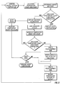
- Figure 2 is a flow chart illustrating a preferred embodiment of the invention.
- FIG. 3 illustrates the control panel of the invention.
- Such implementation-specific decisions may include, and likely are not limited to, compliance with system-related, business-related, government-related and other constraints, which may vary by specific implementation, location and from time to time. While a developer's efforts might be complex and time-consuming in an absolute sense, such efforts would be, nevertheless, a routine undertaking for those of skill in this art having benefit of this disclosure.
- Computer programs for use with or by the embodiments disclosed herein may be written in an object oriented programming language, conventional procedural programming language, or lower-level code, such as assembly language and/or microcode.
- the program may be executed entirely on a single processor and/or across multiple processors, as a stand-alone software package or as part of another software package.
- the improved condensation prevention system accepts input from a user requesting access to the enclosure. Upon receiving input indicating that the user wishes to open the enclosure, the system compares the air temperature and/or humidity within the enclosure to a target temperature and/or humidity.
- the target temperature corresponds to the ambient dewpoint of the air outside the enclosure plus a margin of error. If the ambient dewpoint exceeds the target temperature, the system increases the air temperature within the enclosure until it reaches a temperature at least as high as the target temperature.
- the condensation prevention system includes a display.
- the display shows a warning notification while the air temperature inside the enclosure is lower than the target temperature.
- the warning notification alerts the user that opening the enclosure could lead to the formation of condensation on equipment within the enclosure.
- the display shows a notification advising the user that it is safe to open the enclosure.
- the condensation prevention system includes a timer.
- the timer is activated when the air temperature within the enclosure reaches the target temperature. If the enclosure is not opened in a selected period of time, the system resets and causes the temperature within the enclosure to return to the normal operating temperature.
- the system may be associated with an enclosure 10 containing equipment 20.
- the condensation prevention system may comprise one or more temperature sensors 30 inside the enclosure, a temperature sensor 40 and a humidity sensor 50 outside the enclosure, a control system 60 to regulate the air temperature inside the enclosure, a door open sensor 70 to detect whether an enclosure door 80 is open or closed, and a control panel 90.
- Figure 2 is a flow diagram generally illustrating a preferred method for use with embodiments of the invention.
- the system normally exists in a default condition. In the default condition, the operating temperature within the enclosure is maintained at a selected level appropriate for the optimal functioning of the equipment in the enclosure. While in the default condition, the system compares the air temperature inside the enclosure to the ambient dewpoint outside the enclosure. The system can be programmed to conduct this comparison at selected intervals of time, continuously, and/or at the request of a user. If the system determines that the air temperature inside the enclosure is lower than the ambient dewpoint outside the enclosure, the system causes the display to show a "condensation risk" notification alerting the user that there is a risk of condensation if the enclosure is opened.
- FIG. 3 shows a control panel 90, which may comprise, for example, a display 100 and one or more user inputs 110.
- the control device changes the setpoint temperature to a target temperature that reduces or eliminates the risk of condensation.
- a timer is activated. Once the timer counts down, the display shows a "safe" notification advising the user that it is safe to open the enclosure. The system maintains the temperature inside the enclosure at the target temperature until one of two events takes place.
- the system If the enclosure is not opened within a selected time after the "safe” notification has been given, then the system returns to the default condition and displays the "condensation risk” notification if appropriate. If the enclosure is opened within a selected time after the "safe” notification has been given, then the system will remain in the “safe” condition until the enclosure is closed again. After the enclosure is closed, a timer counts down and the system returns to the default condition and displays the "condensation risk” notification if appropriate.
- a "Do Not Open: Condensation Risk” message appears in the display if the air temperature inside the enclosure is lower than the target temperature.
- the target temperature is the ambient dewpoint temperature of the air outside the enclosure plus a dewpoint margin.
- the dewpoint margin is an arbitrary, pre-selected value, in degrees Fahrenheit or Centigrade, that is added to the ambient dewpoint.
- the dewpoint margin provides a margin of error to compensate for any inaccuracies in the temperature measurements, and provides a safety factor to further reduce the risk of condensation forming on equipment inside the enclosure.
- the dewpoint margin is typically in the range of 1° to 4° Fahrenheit, which corresponds to 0.5° to 2.2° Kelvin, but may be in the range of 0° to 10° depending on the thermal mass of the enclosure and equipment.
- the dewpoint margin is 4° Fahrenheit, which corresponds to 2.2° Kelvin. Therefore, the target temperature in the preferred embodiment is equal to the ambient dewpoint plus 4° Fahrenheit.
- the user requests access to the enclosure by activating an OPEN ACCESS input button 110 on control panel 90. This places the system in the "Access Open” condition.
- the control system then reduces cooling inside the enclosure until the air temperature inside the enclosure reaches the target temperature.
- the system activates a "Access Open Wait Timer.”
- the "Access Open Wait Timer” is a user-selected period of time that reflects the additional time necessary for the surface temperature of the equipment to approach the target temperature.
- the "Access Open Wait Timer” is typically in the range of one to two minutes, but can be longer or shorter depending on the specific application. In the preferred embodiment, the "Access Open Wait Timer" is one minute. After the "Access Open Wait Timer" has finished counting down, the message "Access Open OK" appears in the display.
- the system will maintain the temperature inside that enclosure at the target temperature until one of two events occurs. If the system does not detect a door of the enclosure being opened within two minutes after the "Access Open OK" message appears, then the system will revert to the default condition. The setpoint temperature will be reset to the optimal temperature for the equipment in the enclosure, and normal cooling will resume. Once the air temperature inside the enclosure drops to a level below the target temperature, the "Do Not Open: Condensation Risk” message appears in the display.
- the system detects an access of the enclosure being opened within two minutes after the "Access Open OK" notification appears, then the system maintains the air temperature inside the enclosure at the target temperature until the system detects that all enclosure access points are closed. Once the enclosure is closed, the system activates a two minute "Access Reopen Timer.”
- the "Access Reopen Timer” allows a user to briefly close the enclosure, to retrieve a necessary tool or manual for example, and regain access without having to reset the entire access opening process. If an enclosure access is opened during the two minute "Access Reopen Timer,” then the timer is reset and restarted once the enclosure is closed. When the "Access Reopen Timer" expires without any access having opened, the system returns to the default condition. The setpoint temperature will be reset to the optimal temperature for the equipment in the enclosure, and normal cooling will resume. Once the air temperature inside the enclosure drops to a level below the target temperature, the "Do Not Open: Condensation Risk” message appears in the display.
- the system may be necessary for a user to open the enclosure while the system is in the default condition, even though there is a risk of condensation. If the system detects an enclosure access is opened while the system is in the default condition, the system automatically switches to the "Access Open” condition. The system reduces cooling until the air temperature inside the enclosure reaches the target temperature. The system maintains the target temperature until it detects that the enclosure is once again closed. Once the enclosure is closed, the system will proceed as described above, counting down an "Access Reopen Timer" before returning to the default condition.
- the system further comprises a "High Cabinet Temperature” alarm.
- the "High Cabinet Temperature” alarm is activated if the air temperature inside the enclosure is higher than a user-selected temperature that could damage the equipment in the enclosure.
- the "High Cabinet Temperature” alarm is disabled. Once the system returns to the default condition, the "High Cabinet Temperature” alarm is re-enabled in one of two ways, depending on the air temperature inside the enclosure.
- the control system activates the cooling system inside the enclosure for twenty seconds. After twenty seconds of cooling, the system checks to see whether the air temperature inside the enclosure is lower than it was before the twenty seconds of cooling. If the air temperature has lowered, then normal cooling continues. In this situation, the system will continue to check the air temperature inside the enclosure every twenty seconds to verify that the temperature continues to decrease until it reaches a temperature 3° Fahrenheit below the "High Cabinet Temperature” alarm setpoint. When the air temperature in the enclosure has cooled to a temperature 3° Fahrenheit below the "High Cabinet Temperature” alarm setpoint, the "High Cabinet Temperature” alarm is re-enabled.
- the system will turn off the normal cooling mechanism and activate the backup ventilation for the enclosure.
- the system will take the same action, i.e. turn off the normal cooling mechanism and activate the backup ventilation, at any point in the cooling process if twenty seconds elapse during which the temperature does not drop.
- the system can lock the enclosure accesses to prevent accidental exposure of the equipment to moisture-laden outside air. This embodiment may be prohibitive in critical applications where immediate access to the equipment may be necessary. Selected users may be given special keys or magnetic cards, giving these users the ability to immediately unlock the enclosure in the event of an emergency.
Landscapes
- Engineering & Computer Science (AREA)
- Microelectronics & Electronic Packaging (AREA)
- Chemical & Material Sciences (AREA)
- Combustion & Propulsion (AREA)
- Mechanical Engineering (AREA)
- General Engineering & Computer Science (AREA)
- Physics & Mathematics (AREA)
- Thermal Sciences (AREA)
- Cooling Or The Like Of Electrical Apparatus (AREA)
- Air Conditioning Control Device (AREA)
Description
- BACKGROUND OF THE INVENTION
- Field of the Invention. The inventions disclosed and taught herein relate generally to methods and systems for controlling the environment inside an electronics enclosure; and more specifically related to a method and system for preventing condensation on electronic equipment within an enclosed cabinet.
- Description of the Related Art. Electronic equipment is used for diverse applications in many fields. This equipment must often be installed in environments in which the air temperature or humidity are outside the recommended operating parameters for the equipment. In such cases, it is commonly known to install the equipment in a protective enclosure. The temperature inside the enclosure is controlled to maintain the proper operating environment for the equipment. Depending on the environment outside the enclosure, opening the enclosure can cause moisture to condense on the equipment inside the enclosure. This condensation could damage the equipment and cause it to malfunction. Therefore, it is desirable to regulate the environment within the enclosure to minimize the risk of condensation on the equipment when a user accesses the enclosure.
-
EP 0444570 relates to a cooling system comprising an airtight box which accommodates a cooling module and an electronic device which is cooled by the cooling module and has a door which is opened when attending to maintenance of parts within the airtight box, a dew condensation preventing unit for absorbing humidity within the airtight box and/or replacing air or gas within the airtight box when operated, a coolant supply unit for recirculating a coolant between the coolant supply unit and the cooling module, and a controller for operating the coolant supply unit and the dew condensation preventing unit in response to a first instruction signal which instructs a cooling operation, and for stopping the coolant supply unit in response to a second instruction signal which instructs the maintenance of the parts within the airtight box, where only one of the first and second instruction signals exists at one time. The controller includes a circuit part responsive to the second instruction signal for supplying an operating signal to the electronic device to operate the electronic device for a predetermined time, so that the electronic device rises to a predetermined temperature due to heat generated by the electronic device itself. -
US 5,934,368 relates to a highly reliable electronic apparatus free from condensation in the cabinet of the apparatus. The electronic apparatus has printed circuit boards on which heat emitting semiconductor devices are mounted and a fan. The electronic apparatus further comprises a hygrometer for measuring the relative humidity and dew-point temperature of the cooling air that is introduced into the cabinet through an opening, a surface temperature sensor for sensing the temperature of the surface of the semiconductor devices, an internal temperature sensor for sensing the internal temperature of the semiconductor device, dehumidifier and heater means made up of a heat pump and an outdoor unit, and a controller for controlling the dehumidifier means and the heater means so that the relative humidity is less than 100% and the dew-point temperature is less than the surface temperature of the semiconductor devices. -
JP 2003008275 radiator 10 on the frame surface. The electronic apparatus frame is filled with dry air introduced from an intake valve. A dew point meter in the electronic apparatus monitors the dew point temperature in the frame, and a controller controls the cooling power of the Peltier element, to prevent the dewing in the frame in a dew point temperature range of the dry air. Optimum temperature of the module can be set by the controller. - The inventions disclosed and taught herein are directed to improved systems and methods for regulating the environment within an enclosure so that a user can gain access to the equipment while reducing the risk of condensation forming on the equipment when the enclosure is opened.
- The invention is set out in the independent claims, with some optional features set out in the claims dependent thereto.
- A method of preventing condensation on equipment inside a temperature-controlled enclosure comprises determining the temperature in at least one location inside the enclosure. The temperature inside the enclosure is compared with a target temperature, at which the risk of condensation is reduced. If a user desires access to the inside of the enclosure, the temperature inside the enclosure is increased until the target temperature is achieved. The user is then notified that it is safe to access the enclosure.
- BRIEF DESCRIPTION OF THE SEVERAL VIEWS OF THE DRAWINGS
-
Figure 1 illustrates the condensation prevention system installed on an enclosure containing equipment. -
Figure 2 is a flow chart illustrating a preferred embodiment of the invention. -
Figure 3 illustrates the control panel of the invention. - DETAILED DESCRIPTION
- The Figures described above and the written description of specific structures and functions below are not presented to limit the scope of what Applicants have invented or the scope of the appended claims. Rather, the Figures and written description are provided to teach any person skilled in the art to make and use the inventions for which patent protection is sought. Those skilled in the art will appreciate that not all features of a commercial embodiment of the inventions are described or shown for the sake of clarity and understanding. Persons of skill in this art will also appreciate that the development of an actual commercial embodiment incorporating aspects of the present inventions will require numerous implementation-specific decisions to achieve the developer's ultimate goal for the commercial embodiment. Such implementation-specific decisions may include, and likely are not limited to, compliance with system-related, business-related, government-related and other constraints, which may vary by specific implementation, location and from time to time. While a developer's efforts might be complex and time-consuming in an absolute sense, such efforts would be, nevertheless, a routine undertaking for those of skill in this art having benefit of this disclosure.
- Particular embodiments of the invention may be described below with reference to block diagrams and/or operational illustrations of methods. It will be understood that each block of the block diagrams and/or operational illustrations, and combinations of blocks in the block diagrams and/or operational illustrations, can be implemented by analog and/or digital hardware, and/or computer program instructions. Such computer program instructions may be provided to a processor of a general purpose computer, special purpose computer, ASIC, and/or other programmable data processing system. The executed instructions may create structures and functions for implementing the actions specified in the block diagrams and/or operational illustrations.
- In some alternate implementations, the functions/actions/structures noted in the figures may occur out of the order noted in the block diagrams and/or operational illustrations. For example, two operations shown as occurring in succession, in fact, may be executed substantially concurrently or the operations may be executed in the reverse order, depending upon the functionality/acts/structure involved.
- Computer programs for use with or by the embodiments disclosed herein may be written in an object oriented programming language, conventional procedural programming language, or lower-level code, such as assembly language and/or microcode. The program may be executed entirely on a single processor and/or across multiple processors, as a stand-alone software package or as part of another software package.
- It must be understood that the inventions disclosed and taught herein are susceptible to numerous and various modifications and alternative forms. The use of a singular term, such as, but not limited to, "a," is not intended as limiting of the number of items. Also, the use of relational terms, such as, but not limited to, "top," "bottom," "left," "right," "upper," "lower," "down," "up," "side," and the like are used in the written description for clarity in specific reference to the Figures and are not intended to limit the scope of the invention or the appended claims.
- Applicants have created an improved system for regulating the environment within an enclosure so that a user may open the enclosure without causing condensation to form on equipment within the enclosure. The improved condensation prevention system accepts input from a user requesting access to the enclosure. Upon receiving input indicating that the user wishes to open the enclosure, the system compares the air temperature and/or humidity within the enclosure to a target temperature and/or humidity. In the preferred embodiment, the target temperature corresponds to the ambient dewpoint of the air outside the enclosure plus a margin of error. If the ambient dewpoint exceeds the target temperature, the system increases the air temperature within the enclosure until it reaches a temperature at least as high as the target temperature.
- In one embodiment, the condensation prevention system includes a display. The display shows a warning notification while the air temperature inside the enclosure is lower than the target temperature. The warning notification alerts the user that opening the enclosure could lead to the formation of condensation on equipment within the enclosure. When the temperature inside the enclosure is at least as high as the target temperature, the display shows a notification advising the user that it is safe to open the enclosure.
- In another embodiment, the condensation prevention system includes a timer. The timer is activated when the air temperature within the enclosure reaches the target temperature. If the enclosure is not opened in a selected period of time, the system resets and causes the temperature within the enclosure to return to the normal operating temperature.
- An embodiment of the condensation prevention system utilizing one or more aspects of the present invention is shown in
Figure 1 . The system may be associated with anenclosure 10 containingequipment 20. The condensation prevention system may comprise one ormore temperature sensors 30 inside the enclosure, atemperature sensor 40 and ahumidity sensor 50 outside the enclosure, acontrol system 60 to regulate the air temperature inside the enclosure, a dooropen sensor 70 to detect whether anenclosure door 80 is open or closed, and acontrol panel 90. -
Figure 2 is a flow diagram generally illustrating a preferred method for use with embodiments of the invention. The system normally exists in a default condition. In the default condition, the operating temperature within the enclosure is maintained at a selected level appropriate for the optimal functioning of the equipment in the enclosure. While in the default condition, the system compares the air temperature inside the enclosure to the ambient dewpoint outside the enclosure. The system can be programmed to conduct this comparison at selected intervals of time, continuously, and/or at the request of a user. If the system determines that the air temperature inside the enclosure is lower than the ambient dewpoint outside the enclosure, the system causes the display to show a "condensation risk" notification alerting the user that there is a risk of condensation if the enclosure is opened. - If the user wants to open the enclosure while there is a risk of condensation, the user can request access using the
control panel 90.Figure 3 shows acontrol panel 90, which may comprise, for example, adisplay 100 and one ormore user inputs 110. Once the system receives the user's request for access, the system enters an "Access Open" condition. In the "Access Open" condition, the control device changes the setpoint temperature to a target temperature that reduces or eliminates the risk of condensation. After the temperature inside the enclosure reaches the target temperature a timer is activated. Once the timer counts down, the display shows a "safe" notification advising the user that it is safe to open the enclosure. The system maintains the temperature inside the enclosure at the target temperature until one of two events takes place. If the enclosure is not opened within a selected time after the "safe" notification has been given, then the system returns to the default condition and displays the "condensation risk" notification if appropriate. If the enclosure is opened within a selected time after the "safe" notification has been given, then the system will remain in the "safe" condition until the enclosure is closed again. After the enclosure is closed, a timer counts down and the system returns to the default condition and displays the "condensation risk" notification if appropriate. - The preferred embodiment will now be described. In the default condition, a "Do Not Open: Condensation Risk" message appears in the display if the air temperature inside the enclosure is lower than the target temperature. The target temperature is the ambient dewpoint temperature of the air outside the enclosure plus a dewpoint margin. The dewpoint margin is an arbitrary, pre-selected value, in degrees Fahrenheit or Centigrade, that is added to the ambient dewpoint. The dewpoint margin provides a margin of error to compensate for any inaccuracies in the temperature measurements, and provides a safety factor to further reduce the risk of condensation forming on equipment inside the enclosure. The dewpoint margin is typically in the range of 1° to 4° Fahrenheit, which corresponds to 0.5° to 2.2° Kelvin, but may be in the range of 0° to 10° depending on the thermal mass of the enclosure and equipment. In the preferred embodiment, the dewpoint margin is 4° Fahrenheit, which corresponds to 2.2° Kelvin. Therefore, the target temperature in the preferred embodiment is equal to the ambient dewpoint plus 4° Fahrenheit.
- The user requests access to the enclosure by activating an OPEN
ACCESS input button 110 oncontrol panel 90. This places the system in the "Access Open" condition. The control system then reduces cooling inside the enclosure until the air temperature inside the enclosure reaches the target temperature. When the air temperature inside the enclosure reaches the target temperature, the system activates a "Access Open Wait Timer." The "Access Open Wait Timer" is a user-selected period of time that reflects the additional time necessary for the surface temperature of the equipment to approach the target temperature. The "Access Open Wait Timer" is typically in the range of one to two minutes, but can be longer or shorter depending on the specific application. In the preferred embodiment, the "Access Open Wait Timer" is one minute. After the "Access Open Wait Timer" has finished counting down, the message "Access Open OK" appears in the display. - Once the "Access Open OK" message appears, the system will maintain the temperature inside that enclosure at the target temperature until one of two events occurs. If the system does not detect a door of the enclosure being opened within two minutes after the "Access Open OK" message appears, then the system will revert to the default condition. The setpoint temperature will be reset to the optimal temperature for the equipment in the enclosure, and normal cooling will resume. Once the air temperature inside the enclosure drops to a level below the target temperature, the "Do Not Open: Condensation Risk" message appears in the display.
- If the system detects an access of the enclosure being opened within two minutes after the "Access Open OK" notification appears, then the system maintains the air temperature inside the enclosure at the target temperature until the system detects that all enclosure access points are closed. Once the enclosure is closed, the system activates a two minute "Access Reopen Timer." The "Access Reopen Timer" allows a user to briefly close the enclosure, to retrieve a necessary tool or manual for example, and regain access without having to reset the entire access opening process. If an enclosure access is opened during the two minute "Access Reopen Timer," then the timer is reset and restarted once the enclosure is closed. When the "Access Reopen Timer" expires without any access having opened, the system returns to the default condition. The setpoint temperature will be reset to the optimal temperature for the equipment in the enclosure, and normal cooling will resume. Once the air temperature inside the enclosure drops to a level below the target temperature, the "Do Not Open: Condensation Risk" message appears in the display.
- In some instances, it may be necessary for a user to open the enclosure while the system is in the default condition, even though there is a risk of condensation. If the system detects an enclosure access is opened while the system is in the default condition, the system automatically switches to the "Access Open" condition. The system reduces cooling until the air temperature inside the enclosure reaches the target temperature. The system maintains the target temperature until it detects that the enclosure is once again closed. Once the enclosure is closed, the system will proceed as described above, counting down an "Access Reopen Timer" before returning to the default condition.
- In another embodiment, the system further comprises a "High Cabinet Temperature" alarm. The "High Cabinet Temperature" alarm is activated if the air temperature inside the enclosure is higher than a user-selected temperature that could damage the equipment in the enclosure. When the system is in the "Access Open" condition, the "High Cabinet Temperature" alarm is disabled. Once the system returns to the default condition, the "High Cabinet Temperature" alarm is re-enabled in one of two ways, depending on the air temperature inside the enclosure.
- If the air temperature inside the enclosure is below the "High Cabinet Temperature" alarm setpoint when the system returns to the default condition, then the "High Cabinet Temperature" alarm is re-enabled immediately.
- If the air temperature inside the enclosure is above the "High Cabinet Temperature" alarm setpoint when the system returns to the default condition, then the control system activates the cooling system inside the enclosure for twenty seconds. After twenty seconds of cooling, the system checks to see whether the air temperature inside the enclosure is lower than it was before the twenty seconds of cooling. If the air temperature has lowered, then normal cooling continues. In this situation, the system will continue to check the air temperature inside the enclosure every twenty seconds to verify that the temperature continues to decrease until it reaches a temperature 3° Fahrenheit below the "High Cabinet Temperature" alarm setpoint. When the air temperature in the enclosure has cooled to a temperature 3° Fahrenheit below the "High Cabinet Temperature" alarm setpoint, the "High Cabinet Temperature" alarm is re-enabled. If the air temperature inside the enclosure has not lowered after the first twenty seconds of cooling, then the system will turn off the normal cooling mechanism and activate the backup ventilation for the enclosure. The system will take the same action, i.e. turn off the normal cooling mechanism and activate the backup ventilation, at any point in the cooling process if twenty seconds elapse during which the temperature does not drop.
- In another embodiment, the system can lock the enclosure accesses to prevent accidental exposure of the equipment to moisture-laden outside air. This embodiment may be prohibitive in critical applications where immediate access to the equipment may be necessary. Selected users may be given special keys or magnetic cards, giving these users the ability to immediately unlock the enclosure in the event of an emergency.
- Other and further embodiments utilizing one or more aspects of the inventions described above can be devised. Further, the various methods and embodiments of the condensation prevention system can be included in combination with each other to produce variations of the disclosed methods and embodiments.
- The order of steps can occur in a variety of sequences unless otherwise specifically limited. The various steps described herein can be combined with other steps, interlineated with the stated steps, and/or split into multiple steps. Similarly, elements have been described functionally and can be embodied as separate components or can be combined into components having multiple functions.
- The inventions have been described in the context of preferred and other embodiments and not every embodiment of the invention has been described. Obvious modifications and alterations to the described embodiments are available to those of ordinary skill in the art. The disclosed and undisclosed embodiments are not intended to limit or restrict the scope or applicability of the invention conceived of by the Applicants, but rather, in conformity with the patent laws. Applicants intend to fully protect all such modifications and improvements that come within the scope of the following claims.
Claims (14)
- A method of preventing condensation on equipment within a temperature -controlled enclosure, comprising:determining temperature of air in at least one location inside the enclosure (10);determining an ambient dewpoint temperature of air outside the enclosure (10);comparing the air temperature inside the enclosure (10) to a target temperature that corresponds to the ambient dewpoint of air outside the enclosure (10) plus a marginal dewpoint; andincreasing the temperature inside the enclosure (10) to the target temperature.
- The method of claim 1, in which the marginal dewpoint is between 0.5 and 2.2. Kelvin .
- The method of claim 1, further comprising receiving a request from a user seeking to access the enclosure.
- The method of claim 3, further comprising notifying a user when it is safe to access the enclosure.
- The method of claim 3, further comprising notifying a user when it is not safe to access the enclosure.
- The method of claim 3, further comprising allowing a selected amount of time to pass before notifying the user that it is safe to access the enclosure, after the air temperature inside the enclosure reaches the target temperature.
- The method of claim 3, further comprising returning the air temperature inside the enclosure to a default temperature after the enclosure is closed.
- The method of claim 7, further comprising waiting a selected amount of time after the enclosure is closed before returning the air temperature inside the enclosure to the default temperature.
- A system for preventing condensation on equipment (20) within a temperature-controlled enclosure (10), the system comprising:at least one temperature sensor (30) inside the enclosure (10);at least one temperature sensor (40) outside the enclosure (10);at least one humidity sensor (50) outside the enclosure (10);a control system (60) for regulating the temperature inside the enclosure (10); anda control panel (90) for receiving input from a user and for displaying information about the status of the system characterized bythe system being configured to compare an air temperature inside the enclosure (10) to an ambient dewpoint outside the enclosure (10) wherein if the system receives a request from a user seeking to access the enclosure and if the system determines that the air temperature inside the enclosure (10) is lower than the ambient dewpoint outside the enclosure (10), the control system (60) being configured to cause the air temperature inside the enclosure (10) to increase to a target temperature that is the ambient dewpoint temperature of the air outside the enclosure (10) plus a dewpoint margin.
- The system of claim 9 in which the dewpoint margin is between 0.5 and 2.2 Kelvin.
- The system of claim 9, wherein the system notifies the user when it is safe to open the enclosure,
- The system of claim 11, wherein the system allows a selected amount of time to pass before notifying the user that it is safe to access the enclosure, after the air temperature inside the enclosure reaches the target temperature.
- The system of claim 11, wherein the system returns the air temperature inside the enclosure to a default temperature after the enclosure is closed.
- The system of claim 13, wherein the system waits a selected amount of /3 time after the enclosure is closed before returning the air temperature inside the enclosure to the default temperature.
Applications Claiming Priority (2)
| Application Number | Priority Date | Filing Date | Title |
|---|---|---|---|
| US11/775,604 US7886983B2 (en) | 2007-07-10 | 2007-07-10 | Condensation prevention system and methods of use |
| PCT/US2008/051240 WO2009009155A1 (en) | 2007-07-10 | 2008-01-16 | Condensation prevention system and methods of use |
Publications (2)
| Publication Number | Publication Date |
|---|---|
| EP2177094A1 EP2177094A1 (en) | 2010-04-21 |
| EP2177094B1 true EP2177094B1 (en) | 2013-03-06 |
Family
ID=39591479
Family Applications (1)
| Application Number | Title | Priority Date | Filing Date |
|---|---|---|---|
| EP08705960A Active EP2177094B1 (en) | 2007-07-10 | 2008-01-16 | Condensation prevention system and methods of use |
Country Status (4)
| Country | Link |
|---|---|
| US (2) | US7886983B2 (en) |
| EP (1) | EP2177094B1 (en) |
| CN (1) | CN101731028B (en) |
| WO (1) | WO2009009155A1 (en) |
Families Citing this family (19)
| Publication number | Priority date | Publication date | Assignee | Title |
|---|---|---|---|---|
| JP5104334B2 (en) * | 2008-01-22 | 2012-12-19 | 株式会社島津製作所 | Vacuum pump |
| US20090211773A1 (en) * | 2008-05-02 | 2009-08-27 | Gooch Rodger J | Fire suppression system and associated methods |
| JP5603030B2 (en) * | 2009-06-23 | 2014-10-08 | Dmg森精機株式会社 | Temperature control device for processing machine |
| US20120162343A1 (en) * | 2010-12-27 | 2012-06-28 | Brother Kogyo Kabushiki Kaisha | Image forming apparatus |
| EA024278B1 (en) * | 2013-04-26 | 2016-09-30 | Республиканское Унитарное Предприятие "Институт Жилища - Ниптис Им. Атаева С.С." | Method for preventing moisture condensation on partitions between adjacent rooms with different air temperatures |
| EP3356752B1 (en) * | 2015-09-30 | 2021-04-21 | Electrolux Home Products, Inc. | Temperature control of refrigeration cavities in low ambient temperature conditions |
| US10823439B2 (en) * | 2016-12-14 | 2020-11-03 | Dell Products L.P. | Systems and methods for reliability control of information handling system |
| CN108255215A (en) * | 2017-12-08 | 2018-07-06 | 东莞市升微机电设备科技有限公司 | A kind of electronic cooling anti-condensation system and its anti-condensation method |
| US11287172B2 (en) | 2018-01-29 | 2022-03-29 | Tippmann Companies Llc | Freezer dehumidification system |
| CA3055363A1 (en) | 2018-09-28 | 2020-03-28 | Tmeic Corporation | Hvac-less enclosure with temperature range augmenting recirculation system |
| DE102019204300A1 (en) * | 2019-03-28 | 2020-10-01 | Siemens Aktiengesellschaft | High-voltage device and method for determining the risk of condensation in cabinets in such a high-voltage device |
| US11526044B2 (en) | 2020-03-27 | 2022-12-13 | Manufacturing Resources International, Inc. | Display unit with orientation based operation |
| US11561045B1 (en) | 2020-04-15 | 2023-01-24 | Thomas Cline | Power supply and method to deter mold |
| US12022635B2 (en) * | 2021-03-15 | 2024-06-25 | Manufacturing Resources International, Inc. | Fan control for electronic display assemblies |
| US12105370B2 (en) | 2021-03-15 | 2024-10-01 | Manufacturing Resources International, Inc. | Fan control for electronic display assemblies |
| CN113654189B (en) * | 2021-08-04 | 2023-02-17 | 青岛海尔空调器有限总公司 | Air conditioner anti-condensation control method and system, electronic equipment and storage medium |
| US20230138106A1 (en) * | 2021-10-28 | 2023-05-04 | Caterpillar Inc. | Containerized battery system and anti-condensation control system for same |
| KR20250121378A (en) * | 2022-12-09 | 2025-08-12 | 선전 인왕 인텔리전트 테크놀로지스 컴퍼니 리미티드 | Integrated device, cooling system, cooling method and terminal |
| US12027132B1 (en) | 2023-06-27 | 2024-07-02 | Manufacturing Resources International, Inc. | Display units with automated power governing |
Family Cites Families (50)
| Publication number | Priority date | Publication date | Assignee | Title |
|---|---|---|---|---|
| US4512161A (en) * | 1983-03-03 | 1985-04-23 | Control Data Corporation | Dew point sensitive computer cooling system |
| US4572427A (en) * | 1984-03-02 | 1986-02-25 | Mallinckrodt, Inc. | Controlled atmosphere enclosure |
| JPH0331637A (en) * | 1989-06-29 | 1991-02-12 | Omron Corp | Indoor environment maintaining device |
| JP2910127B2 (en) * | 1990-03-01 | 1999-06-23 | 富士通株式会社 | Cooling system |
| US5043143A (en) * | 1990-03-28 | 1991-08-27 | Eastman Kodak Company | Analyzer having humidity control apparatus |
| US5144811A (en) * | 1991-01-10 | 1992-09-08 | Hughes Aircraft Company | Condensation control system for water-cooled electronics |
| US5259553A (en) * | 1991-04-05 | 1993-11-09 | Norm Pacific Automation Corp. | Interior atmosphere control system |
| SE9304264L (en) * | 1993-12-22 | 1995-06-23 | Ericsson Telefon Ab L M | Method and apparatus for cooling in closed rooms |
| JP3232908B2 (en) * | 1994-09-20 | 2001-11-26 | 株式会社日立製作所 | Electronic equipment |
| JPH0926255A (en) * | 1995-07-07 | 1997-01-28 | Kawamura Electric Inc | Alarm device for frozen showcase |
| AU7379396A (en) * | 1995-09-28 | 1997-04-17 | De Marsillac Plunkett Architecture, P.C. | Refrigerator for securely accepting deliveries |
| JP3290583B2 (en) * | 1996-02-15 | 2002-06-10 | カルソニックカンセイ株式会社 | Automotive air conditioners |
| US6223817B1 (en) * | 1996-04-25 | 2001-05-01 | Royal Vendors, Inc. | Electronic refrigeration control system |
| KR19980054656A (en) * | 1996-12-27 | 1998-09-25 | 배순훈 | How to operate air curtain fan |
| US5778689A (en) * | 1997-05-19 | 1998-07-14 | Beatenbough; Bryan | System for maintaining refrigeration doors free of frost and condensation |
| US5960638A (en) * | 1997-08-15 | 1999-10-05 | Huntair Inc. | Modular environmental control unit for cleanrooms |
| US6454176B1 (en) * | 1999-09-28 | 2002-09-24 | Henny Penny Corporation | Holding cabinet with closed-loop humidity control system and method for controlling humidity in a holding cabinet |
| US6161765A (en) * | 1999-09-30 | 2000-12-19 | Lucent Technologies, Inc. | Outdoor enclosure with heated desiccant |
| DE19947945C2 (en) * | 1999-10-06 | 2003-04-30 | Gerd Arnold | Method for controlling ventilation from an interior |
| GB9928050D0 (en) * | 1999-11-26 | 2000-01-26 | Tyco Electronics Raychem Gmbh | Heating arrangement |
| EP1266548B2 (en) * | 2000-03-21 | 2015-07-29 | Liebert Corporation | Method and apparatus for cooling electronic enclosures |
| US20010053963A1 (en) * | 2000-06-16 | 2001-12-20 | Lg Electronics Inc. | Refrigerator and method for controlling the same |
| US6705389B1 (en) * | 2000-07-17 | 2004-03-16 | Emerson Electric Co. | Reconfigurable system and method for cooling heat generating objects |
| US6564571B2 (en) * | 2000-07-17 | 2003-05-20 | Liebert Corporation | High availability energy |
| US6564858B1 (en) * | 2000-07-17 | 2003-05-20 | Liebert Corporation | Overhead cooling system with selectively positioned paths of airflow |
| US6557624B1 (en) * | 2000-08-09 | 2003-05-06 | Liebert Corporation | Configurable system and method for cooling a room |
| US6563048B2 (en) * | 2000-10-27 | 2003-05-13 | Liebert Corporation | Ancillary cabinet system for an uninterruptible power supply |
| US6754066B2 (en) * | 2000-10-27 | 2004-06-22 | Liebert Corporation | UPS cabinet and method of assembly |
| US6881898B2 (en) * | 2001-03-02 | 2005-04-19 | Liebert Corporation | Remote distribution cabinet |
| JP2003008275A (en) | 2001-06-22 | 2003-01-10 | Nec Network Sensa Kk | Cooling structure of electronic apparatus, and cooling system thereof |
| US6854659B2 (en) * | 2001-09-21 | 2005-02-15 | Kliebert Corporation | Interactive sensors for environmental control |
| US20030205059A1 (en) * | 2002-05-02 | 2003-11-06 | Hussmann Corporation | Merchandisers having anti-fog coatings and methods for making the same |
| KR20040017978A (en) * | 2002-08-23 | 2004-03-02 | 삼성전자주식회사 | Refrigerator and control method thereof |
| US7255640B2 (en) * | 2002-10-11 | 2007-08-14 | Liebert Corporation | Cable and air management adapter system for enclosures housing electronic equipment |
| WO2004072785A2 (en) * | 2003-02-07 | 2004-08-26 | Geocentric Systems | Self-contained keyless entry system to prevent lockout from restricted-access spaces |
| US6996997B2 (en) * | 2003-03-05 | 2006-02-14 | Thermo King Corporation | Pre-trip diagnostic methods for a temperature control unit |
| DE10310282A1 (en) * | 2003-03-07 | 2004-09-16 | Rittal Gmbh & Co. Kg | Liquid cooling system |
| US6840052B2 (en) * | 2003-04-17 | 2005-01-11 | Wade W. Smith | Air conditioning system |
| US7051946B2 (en) * | 2003-05-29 | 2006-05-30 | Hewlett-Packard Development Company, L.P. | Air re-circulation index |
| US7032397B1 (en) * | 2003-09-09 | 2006-04-25 | Emerson Electric Co. | Thermostat for use with compressor health indicator |
| CA2540073A1 (en) * | 2003-09-26 | 2005-04-07 | David Howard Ambrose | System for alleviating in-vault condensation in double-glazed windows |
| US7137262B2 (en) * | 2003-12-05 | 2006-11-21 | Kendro Laboratory Products, Lp | Supplemental heat control apparatus and method for freezer/refrigeration equipment |
| US20050207116A1 (en) * | 2004-03-22 | 2005-09-22 | Yatskov Alexander I | Systems and methods for inter-cooling computer cabinets |
| JP2006114532A (en) | 2004-10-12 | 2006-04-27 | Denso Corp | Cooling system |
| US7472554B2 (en) * | 2005-02-14 | 2009-01-06 | Continental Teves, Inc. | Passenger environmental protection |
| US7448435B2 (en) * | 2005-02-23 | 2008-11-11 | Emerson Electric Co. | System and method for controlling a multi-zone heating or cooling system |
| US7207181B2 (en) * | 2005-03-01 | 2007-04-24 | Bradley W. Geuke | Refrigeration unit condensation prevention |
| US7631509B2 (en) * | 2005-04-27 | 2009-12-15 | Gideon Shavit | Integrated freezer-anteroom control |
| WO2007018994A2 (en) * | 2005-08-04 | 2007-02-15 | Liebert Corporation | Electronic equipment cabinet with integrated, high capacity, cooling system, and backup ventilation system |
| US7905101B2 (en) * | 2006-12-15 | 2011-03-15 | Hussmann Corporation | Refrigerated merchandiser with glass door heat control |
-
2007
- 2007-07-10 US US11/775,604 patent/US7886983B2/en active Active
-
2008
- 2008-01-16 EP EP08705960A patent/EP2177094B1/en active Active
- 2008-01-16 CN CN2008800239049A patent/CN101731028B/en active Active
- 2008-01-16 WO PCT/US2008/051240 patent/WO2009009155A1/en not_active Ceased
-
2011
- 2011-01-06 US US12/986,035 patent/US20110101118A1/en not_active Abandoned
Also Published As
| Publication number | Publication date |
|---|---|
| CN101731028B (en) | 2012-06-13 |
| US20090014548A1 (en) | 2009-01-15 |
| US7886983B2 (en) | 2011-02-15 |
| CN101731028A (en) | 2010-06-09 |
| EP2177094A1 (en) | 2010-04-21 |
| US20110101118A1 (en) | 2011-05-05 |
| WO2009009155A1 (en) | 2009-01-15 |
Similar Documents
| Publication | Publication Date | Title |
|---|---|---|
| US7886983B2 (en) | Condensation prevention system and methods of use | |
| US11098911B2 (en) | HVAC scrubber unit with building management system integration systems and methods | |
| JP4766499B2 (en) | Outdoor image display device | |
| US9737740B2 (en) | Temperature-control system and method | |
| US5467607A (en) | Air conditioning control system | |
| US8527096B2 (en) | Programmable controller and a user interface for same | |
| US9887513B2 (en) | Laser apparatus having condensation prevention function | |
| JP6051829B2 (en) | Fan control device | |
| EP2138922B1 (en) | Method for fan control according to the position of a device and device implementing the procedure | |
| JP2003186566A (en) | Self-adjustment clock of computer system adjusting in response to the change of environment | |
| US20250198637A1 (en) | Venting for Enclosure Cooling | |
| JP2009299919A (en) | Energy saving system | |
| JP5750996B2 (en) | Rack device, rack system, and housing structure | |
| US11681266B2 (en) | Data center management system that controls environmental conditions to facilitate operating state changes of individual equipment | |
| CN114061259A (en) | Control method of refrigeration equipment | |
| SE544494C2 (en) | Temperature controller for a temperature control mechanism | |
| US20210219462A1 (en) | Data center cooling system that prevents condensation caused by opening external access doors | |
| US20210215390A1 (en) | Condensation protection tray | |
| JP5880281B2 (en) | Temperature management system | |
| JPH09250489A (en) | Cooling fan rotation speed control device | |
| JPH0447327B2 (en) | ||
| JPS61122469A (en) | Air cooling device | |
| CN106369738A (en) | Novel computer room environment maintaining method | |
| CN108777920A (en) | A kind of power regulation operation console | |
| JPH02230054A (en) | Freezer |
Legal Events
| Date | Code | Title | Description |
|---|---|---|---|
| PUAI | Public reference made under article 153(3) epc to a published international application that has entered the european phase |
Free format text: ORIGINAL CODE: 0009012 |
|
| 17P | Request for examination filed |
Effective date: 20100209 |
|
| AK | Designated contracting states |
Kind code of ref document: A1 Designated state(s): AT BE BG CH CY CZ DE DK EE ES FI FR GB GR HR HU IE IS IT LI LT LU LV MC MT NL NO PL PT RO SE SI SK TR |
|
| AX | Request for extension of the european patent |
Extension state: AL BA MK RS |
|
| 17Q | First examination report despatched |
Effective date: 20100430 |
|
| DAX | Request for extension of the european patent (deleted) | ||
| GRAP | Despatch of communication of intention to grant a patent |
Free format text: ORIGINAL CODE: EPIDOSNIGR1 |
|
| GRAS | Grant fee paid |
Free format text: ORIGINAL CODE: EPIDOSNIGR3 |
|
| GRAA | (expected) grant |
Free format text: ORIGINAL CODE: 0009210 |
|
| AK | Designated contracting states |
Kind code of ref document: B1 Designated state(s): AT BE BG CH CY CZ DE DK EE ES FI FR GB GR HR HU IE IS IT LI LT LU LV MC MT NL NO PL PT RO SE SI SK TR |
|
| REG | Reference to a national code |
Ref country code: GB Ref legal event code: FG4D |
|
| REG | Reference to a national code |
Ref country code: AT Ref legal event code: REF Ref document number: 600225 Country of ref document: AT Kind code of ref document: T Effective date: 20130315 Ref country code: CH Ref legal event code: EP |
|
| REG | Reference to a national code |
Ref country code: IE Ref legal event code: FG4D |
|
| REG | Reference to a national code |
Ref country code: DE Ref legal event code: R096 Ref document number: 602008022689 Country of ref document: DE Effective date: 20130502 |
|
| REG | Reference to a national code |
Ref country code: AT Ref legal event code: MK05 Ref document number: 600225 Country of ref document: AT Kind code of ref document: T Effective date: 20130306 |
|
| PG25 | Lapsed in a contracting state [announced via postgrant information from national office to epo] |
Ref country code: LT Free format text: LAPSE BECAUSE OF FAILURE TO SUBMIT A TRANSLATION OF THE DESCRIPTION OR TO PAY THE FEE WITHIN THE PRESCRIBED TIME-LIMIT Effective date: 20130306 Ref country code: SE Free format text: LAPSE BECAUSE OF FAILURE TO SUBMIT A TRANSLATION OF THE DESCRIPTION OR TO PAY THE FEE WITHIN THE PRESCRIBED TIME-LIMIT Effective date: 20130306 Ref country code: BG Free format text: LAPSE BECAUSE OF FAILURE TO SUBMIT A TRANSLATION OF THE DESCRIPTION OR TO PAY THE FEE WITHIN THE PRESCRIBED TIME-LIMIT Effective date: 20130606 Ref country code: ES Free format text: LAPSE BECAUSE OF FAILURE TO SUBMIT A TRANSLATION OF THE DESCRIPTION OR TO PAY THE FEE WITHIN THE PRESCRIBED TIME-LIMIT Effective date: 20130617 Ref country code: NO Free format text: LAPSE BECAUSE OF FAILURE TO SUBMIT A TRANSLATION OF THE DESCRIPTION OR TO PAY THE FEE WITHIN THE PRESCRIBED TIME-LIMIT Effective date: 20130606 Ref country code: AT Free format text: LAPSE BECAUSE OF FAILURE TO SUBMIT A TRANSLATION OF THE DESCRIPTION OR TO PAY THE FEE WITHIN THE PRESCRIBED TIME-LIMIT Effective date: 20130306 |
|
| REG | Reference to a national code |
Ref country code: NL Ref legal event code: VDEP Effective date: 20130306 |
|
| REG | Reference to a national code |
Ref country code: LT Ref legal event code: MG4D |
|
| PG25 | Lapsed in a contracting state [announced via postgrant information from national office to epo] |
Ref country code: SI Free format text: LAPSE BECAUSE OF FAILURE TO SUBMIT A TRANSLATION OF THE DESCRIPTION OR TO PAY THE FEE WITHIN THE PRESCRIBED TIME-LIMIT Effective date: 20130306 Ref country code: LV Free format text: LAPSE BECAUSE OF FAILURE TO SUBMIT A TRANSLATION OF THE DESCRIPTION OR TO PAY THE FEE WITHIN THE PRESCRIBED TIME-LIMIT Effective date: 20130306 Ref country code: FI Free format text: LAPSE BECAUSE OF FAILURE TO SUBMIT A TRANSLATION OF THE DESCRIPTION OR TO PAY THE FEE WITHIN THE PRESCRIBED TIME-LIMIT Effective date: 20130306 Ref country code: GR Free format text: LAPSE BECAUSE OF FAILURE TO SUBMIT A TRANSLATION OF THE DESCRIPTION OR TO PAY THE FEE WITHIN THE PRESCRIBED TIME-LIMIT Effective date: 20130607 |
|
| PG25 | Lapsed in a contracting state [announced via postgrant information from national office to epo] |
Ref country code: HR Free format text: LAPSE BECAUSE OF FAILURE TO SUBMIT A TRANSLATION OF THE DESCRIPTION OR TO PAY THE FEE WITHIN THE PRESCRIBED TIME-LIMIT Effective date: 20130306 Ref country code: BE Free format text: LAPSE BECAUSE OF FAILURE TO SUBMIT A TRANSLATION OF THE DESCRIPTION OR TO PAY THE FEE WITHIN THE PRESCRIBED TIME-LIMIT Effective date: 20130306 |
|
| PG25 | Lapsed in a contracting state [announced via postgrant information from national office to epo] |
Ref country code: RO Free format text: LAPSE BECAUSE OF FAILURE TO SUBMIT A TRANSLATION OF THE DESCRIPTION OR TO PAY THE FEE WITHIN THE PRESCRIBED TIME-LIMIT Effective date: 20130306 Ref country code: CZ Free format text: LAPSE BECAUSE OF FAILURE TO SUBMIT A TRANSLATION OF THE DESCRIPTION OR TO PAY THE FEE WITHIN THE PRESCRIBED TIME-LIMIT Effective date: 20130306 Ref country code: SK Free format text: LAPSE BECAUSE OF FAILURE TO SUBMIT A TRANSLATION OF THE DESCRIPTION OR TO PAY THE FEE WITHIN THE PRESCRIBED TIME-LIMIT Effective date: 20130306 Ref country code: IS Free format text: LAPSE BECAUSE OF FAILURE TO SUBMIT A TRANSLATION OF THE DESCRIPTION OR TO PAY THE FEE WITHIN THE PRESCRIBED TIME-LIMIT Effective date: 20130706 Ref country code: NL Free format text: LAPSE BECAUSE OF FAILURE TO SUBMIT A TRANSLATION OF THE DESCRIPTION OR TO PAY THE FEE WITHIN THE PRESCRIBED TIME-LIMIT Effective date: 20130306 Ref country code: PT Free format text: LAPSE BECAUSE OF FAILURE TO SUBMIT A TRANSLATION OF THE DESCRIPTION OR TO PAY THE FEE WITHIN THE PRESCRIBED TIME-LIMIT Effective date: 20130708 Ref country code: EE Free format text: LAPSE BECAUSE OF FAILURE TO SUBMIT A TRANSLATION OF THE DESCRIPTION OR TO PAY THE FEE WITHIN THE PRESCRIBED TIME-LIMIT Effective date: 20130306 |
|
| PG25 | Lapsed in a contracting state [announced via postgrant information from national office to epo] |
Ref country code: CY Free format text: LAPSE BECAUSE OF FAILURE TO SUBMIT A TRANSLATION OF THE DESCRIPTION OR TO PAY THE FEE WITHIN THE PRESCRIBED TIME-LIMIT Effective date: 20130306 Ref country code: PL Free format text: LAPSE BECAUSE OF FAILURE TO SUBMIT A TRANSLATION OF THE DESCRIPTION OR TO PAY THE FEE WITHIN THE PRESCRIBED TIME-LIMIT Effective date: 20130306 |
|
| PLBE | No opposition filed within time limit |
Free format text: ORIGINAL CODE: 0009261 |
|
| STAA | Information on the status of an ep patent application or granted ep patent |
Free format text: STATUS: NO OPPOSITION FILED WITHIN TIME LIMIT |
|
| PG25 | Lapsed in a contracting state [announced via postgrant information from national office to epo] |
Ref country code: DK Free format text: LAPSE BECAUSE OF FAILURE TO SUBMIT A TRANSLATION OF THE DESCRIPTION OR TO PAY THE FEE WITHIN THE PRESCRIBED TIME-LIMIT Effective date: 20130306 |
|
| 26N | No opposition filed |
Effective date: 20131209 |
|
| REG | Reference to a national code |
Ref country code: DE Ref legal event code: R097 Ref document number: 602008022689 Country of ref document: DE Effective date: 20131209 |
|
| PG25 | Lapsed in a contracting state [announced via postgrant information from national office to epo] |
Ref country code: LU Free format text: LAPSE BECAUSE OF FAILURE TO SUBMIT A TRANSLATION OF THE DESCRIPTION OR TO PAY THE FEE WITHIN THE PRESCRIBED TIME-LIMIT Effective date: 20140116 Ref country code: MC Free format text: LAPSE BECAUSE OF FAILURE TO SUBMIT A TRANSLATION OF THE DESCRIPTION OR TO PAY THE FEE WITHIN THE PRESCRIBED TIME-LIMIT Effective date: 20130306 |
|
| REG | Reference to a national code |
Ref country code: CH Ref legal event code: PL |
|
| PG25 | Lapsed in a contracting state [announced via postgrant information from national office to epo] |
Ref country code: LI Free format text: LAPSE BECAUSE OF NON-PAYMENT OF DUE FEES Effective date: 20140131 Ref country code: CH Free format text: LAPSE BECAUSE OF NON-PAYMENT OF DUE FEES Effective date: 20140131 |
|
| REG | Reference to a national code |
Ref country code: IE Ref legal event code: MM4A |
|
| PG25 | Lapsed in a contracting state [announced via postgrant information from national office to epo] |
Ref country code: IE Free format text: LAPSE BECAUSE OF NON-PAYMENT OF DUE FEES Effective date: 20140116 |
|
| REG | Reference to a national code |
Ref country code: FR Ref legal event code: PLFP Year of fee payment: 9 |
|
| PG25 | Lapsed in a contracting state [announced via postgrant information from national office to epo] |
Ref country code: MT Free format text: LAPSE BECAUSE OF FAILURE TO SUBMIT A TRANSLATION OF THE DESCRIPTION OR TO PAY THE FEE WITHIN THE PRESCRIBED TIME-LIMIT Effective date: 20130306 |
|
| PG25 | Lapsed in a contracting state [announced via postgrant information from national office to epo] |
Ref country code: TR Free format text: LAPSE BECAUSE OF FAILURE TO SUBMIT A TRANSLATION OF THE DESCRIPTION OR TO PAY THE FEE WITHIN THE PRESCRIBED TIME-LIMIT Effective date: 20130306 Ref country code: HU Free format text: LAPSE BECAUSE OF FAILURE TO SUBMIT A TRANSLATION OF THE DESCRIPTION OR TO PAY THE FEE WITHIN THE PRESCRIBED TIME-LIMIT; INVALID AB INITIO Effective date: 20080116 |
|
| REG | Reference to a national code |
Ref country code: FR Ref legal event code: PLFP Year of fee payment: 10 |
|
| REG | Reference to a national code |
Ref country code: FR Ref legal event code: PLFP Year of fee payment: 11 |
|
| REG | Reference to a national code |
Ref country code: DE Ref legal event code: R082 Ref document number: 602008022689 Country of ref document: DE Representative=s name: GROSSE, SCHUMACHER, KNAUER, VON HIRSCHHAUSEN, DE Ref country code: DE Ref legal event code: R081 Ref document number: 602008022689 Country of ref document: DE Owner name: VERTIV CORP., COLUMBUS, US Free format text: FORMER OWNER: LIEBERT CORP., COLUMBUS, OHIO, US |
|
| P01 | Opt-out of the competence of the unified patent court (upc) registered |
Effective date: 20230621 |
|
| PGFP | Annual fee paid to national office [announced via postgrant information from national office to epo] |
Ref country code: GB Payment date: 20260127 Year of fee payment: 19 |
|
| PGFP | Annual fee paid to national office [announced via postgrant information from national office to epo] |
Ref country code: DE Payment date: 20260128 Year of fee payment: 19 |
|
| PGFP | Annual fee paid to national office [announced via postgrant information from national office to epo] |
Ref country code: IT Payment date: 20260121 Year of fee payment: 19 |
|
| PGFP | Annual fee paid to national office [announced via postgrant information from national office to epo] |
Ref country code: FR Payment date: 20260126 Year of fee payment: 19 |