EP2176829B1 - Arrangement and method for processing image data - Google Patents
Arrangement and method for processing image data Download PDFInfo
- Publication number
- EP2176829B1 EP2176829B1 EP08826248A EP08826248A EP2176829B1 EP 2176829 B1 EP2176829 B1 EP 2176829B1 EP 08826248 A EP08826248 A EP 08826248A EP 08826248 A EP08826248 A EP 08826248A EP 2176829 B1 EP2176829 B1 EP 2176829B1
- Authority
- EP
- European Patent Office
- Prior art keywords
- pixel
- data
- detection block
- image
- video frame
- Prior art date
- Legal status (The legal status is an assumption and is not a legal conclusion. Google has not performed a legal analysis and makes no representation as to the accuracy of the status listed.)
- Not-in-force
Links
- 238000000034 method Methods 0.000 title claims abstract description 22
- 238000012545 processing Methods 0.000 title claims description 45
- 238000001514 detection method Methods 0.000 claims abstract description 135
- 239000003086 colorant Substances 0.000 claims description 8
- 238000013507 mapping Methods 0.000 description 14
- 238000010586 diagram Methods 0.000 description 9
- 238000013459 approach Methods 0.000 description 4
- 230000001939 inductive effect Effects 0.000 description 3
- 230000010354 integration Effects 0.000 description 3
- 230000008569 process Effects 0.000 description 3
- 238000006243 chemical reaction Methods 0.000 description 2
- 239000007943 implant Substances 0.000 description 2
- 238000012544 monitoring process Methods 0.000 description 2
- 238000013519 translation Methods 0.000 description 2
- 230000004075 alteration Effects 0.000 description 1
- 238000003491 array Methods 0.000 description 1
- 230000008859 change Effects 0.000 description 1
- 238000011161 development Methods 0.000 description 1
- 230000006870 function Effects 0.000 description 1
- 230000006872 improvement Effects 0.000 description 1
- 238000012423 maintenance Methods 0.000 description 1
- 239000004065 semiconductor Substances 0.000 description 1
- 238000001228 spectrum Methods 0.000 description 1
- 230000000007 visual effect Effects 0.000 description 1
Images


Classifications
-
- G—PHYSICS
- G06—COMPUTING; CALCULATING OR COUNTING
- G06T—IMAGE DATA PROCESSING OR GENERATION, IN GENERAL
- G06T3/00—Geometric image transformations in the plane of the image
- G06T3/40—Scaling of whole images or parts thereof, e.g. expanding or contracting
- G06T3/4015—Image demosaicing, e.g. colour filter arrays [CFA] or Bayer patterns
-
- G—PHYSICS
- G06—COMPUTING; CALCULATING OR COUNTING
- G06T—IMAGE DATA PROCESSING OR GENERATION, IN GENERAL
- G06T2207/00—Indexing scheme for image analysis or image enhancement
- G06T2207/10—Image acquisition modality
- G06T2207/10016—Video; Image sequence
-
- G—PHYSICS
- G06—COMPUTING; CALCULATING OR COUNTING
- G06T—IMAGE DATA PROCESSING OR GENERATION, IN GENERAL
- G06T2207/00—Indexing scheme for image analysis or image enhancement
- G06T2207/30—Subject of image; Context of image processing
- G06T2207/30236—Traffic on road, railway or crossing
Definitions
- the present invention relates generally to image capture and detection systems, and more particularly to methods and arrangements for obtaining image data.
- Detection of the presence and/or approach of vehicles allows for improved efficiency in traffic control.
- a traffic signal may not change to green for a cross street for an indefinite time if there are no vehicles present on the cross street awaiting the signal. However, if a vehicle approaches the intersection on the cross street, the traffic signal may be changed responsive to the detection of such approach.
- vehicle detection for traffic control has employed inductive sensors located under the road surface.
- the entrance of the automobile into a region near the inductive sensor changes the sensed magnetic field, thus enabling detection of the vehicle.
- a drawback of these systems is the need to implant the inductive sensors under or in the road surface pavement, which requires significant labor and traffic interruption. Because video cameras avoid the need to implant equipment below the road surface, camera-based vehicle detection systems are increasingly desirable.
- Camera-based vehicle detection systems using video processing are known.
- One type of vehicle detection system performs vehicle detection on select areas of available video frames provided by a video camera.
- a video camera provides video frame information, typically in a format known as the Bayer format, to a processing system.
- the processing system converts the Bayer formatted video to (red-green-blue) RGB formatted video, which is (or is similar to) the format employed by most digital video systems.
- the RGB formatted video is then provided to the detection subsystem and optionally to a viewing device, such as a remotely located laptop or portable computer.
- the detection subsystem then employs homographic mapping to isolate specific, select areas of the video frame for the actual detection algorithms.
- vehicle detection typically does not occur within an entire video frame, but rather in isolated areas such as portions of a road or near specific objects.
- the desired areas for detection are then converted into detection blocks that are standardized for the detection algorithms.
- a small trapezoidal area of interest in or near an intersection is converted into a rectangle of a size and orientation that is suitable for the detection algorithms.
- the portion of the video image that is to be analyzed is stored as a detection block.
- the video data corresponding to the area of interest is transferred into the detection block via homographic mapping or warping.
- the detection block thus represents video data from the select area of interest.
- the detection algorithms then operate with the detection blocks in order to identify whether moving objects are within the select area of interest.
- the detection operations include integration, autocorrelation, center of chromatic mass, background processing, among others to detect moving vehicles and/or any presence of vehicles.
- Algorithmic detection of vehicles using the above techniques consumes a large amount of computational processing power.
- the processing engines that are commonly available in the wider temperature range are quite limited in the maximum processing speed available. Executing the necessary video processing for vehicle detection can cause such processors to run "too hot”.
- Fig. 1 shows a block diagram of a system 100 for image processing that includes at least one embodiment of the invention.
- the system 100 includes a source of video frame data 102, a vehicle detection arrangement 104 and at least one remote user interface 106.
- the source of video frame data 102 is a device or set of devices that is configured to provide video frame data in a first format.
- the first format of video frame data includes a plurality of pixels, each pixel containing single color data.
- the source of video frame data 102 is a digital camera or digital video camera that employs a high-speed CCD (Charge-Coupled Device) or CMOS (Complementary-Metal-Oxide-Semiconductor) light-sensitive imager arrays as an initial sensor. This array outputs data values corresponding to individual pixels (individual small picture elements) according to how much light intensity is measured at that particular pixel within the imager array.
- CCD Charge-Coupled Device
- CMOS Complementary-Metal-Oxide-Semiconductor
- the first format of the video frame data may suitably comprise a mosaic formatted data.
- many video cameras are configured to generate mosaiced pixel data, sometimes referred to as Bayer-formatted data.
- Bayer format cameras typically includes a color mosaic lens positioned in front of an array of monochrome CCD detectors, and transmit the luminance value for each element instead of the individual color components.
- Fig. 7 shows an exemplary embodiment that employs a mosaic lens camera 130.
- Such a source effectively transmits only one color component value per pixel, and for each four pixels transferred, two are green pixels, one is a blue pixel, and one is a red pixel.
- green-spectrum video information is effectively subsampled at 50% resolution, while red and blue information is each effectively subsampled at 25% resolution.
- the frame data includes a plurality of pixels having only single-color information.
- FIG. 4 shows a diagram of a portion 402 of a video frame in single color or mosaiced format.
- the portion 402 includes a mosaic of single color red, blue and green pixels 404, 406 and 408 respectively.
- Implementation of the invention is not limited to the particular single color mosaic formats shown in Fig. 4 . At least some embodiments of the invention are compatible with each of the four possible Bayer formats, and can readily be adapted to other similar subsampling mosaic patterns.
- the source of video frame data 102 is operably coupled to provide the video frame data in the first format to each of the video detection arrangement 104 and the remote user interface 106.
- the video detection arrangement 104 includes data processing equipment and associated circuitry that is capable of performing image processing as described herein.
- the video detection arrangement 104 is configured to employ homographic mapping to generate a detection block from the video frame data.
- the detection block is representative of a select subset of the video frame image, and typically includes a portion of the image that has been preselected as potentially containing vehicles to be detected.
- Homographic mapping (or warping) is employed to generate a re-aligned view, for example, a rectangle generated from a trapezoid, such that angled points of view are rectified into a normal (i.e perpendicular) point of view which aids the detection algorithms.
- a vehicle detection system may be used in a security system or other surveillance system that employs rotating cameras.
- homographic mapping allows various points of view from a moving (e.g. rotating) camera to be compared and processed from the same point of view.
- the vehicle detection system may be connected to receive the video frame data from cameras used for general surveillance. General surveillance cameras often are configured to rotate to cover more area.
- the source of video data 102 in this embodiment is typically a stationary image capturing device.
- the homographic mapping is used to map select portions (and non-standard shapes) of video data into a detection block.
- the detection block has a size and shape (square or rectangular) that is compatible with the detection algorithms.
- the select portion of the video data is often user selected and will often have at least some dimensions (size, shape) that differ from that of the detection block, and typically is significantly larger.
- Figs. 2 and 3 illustrate by way of example how homographic mapping is employed to generate consistent, normalized representations of select (and variably shaped and sized) portions of a video frame image.
- Fig. 2 shows a camera 202 (which may suitably be used as the source of video information 102 of Fig. 1 ), and an image frame 204.
- the image frame 204 consists of the two dimensional field of vision of the camera 202.
- a user has defined two areas of interest 206, 208 in the image frame.
- these areas of interest 206, 208 may include approaches to different parts of a traffic intersection.
- the areas of interest 206, 208 are in different locations within the image frame 204, have different shapes, and have different sizes.
- Fig. 3 shows a representation of two dimensional views of the image frame 204, the areas of interest or image portions 206, 208 and corresponding detector blocks 210, 212.
- Homographic mapping techniques are used to map the image portions 206, 208 to like-sized and similarly oriented detection blocks 210, 212.
- the detection algorithms not shown, then work with the detection blocks 210, 212. As a consequence, the same detection algorithms may be used for a variety of image portions having unique size, shape and orientation. Such homographic morphing techniques are known.
- the vehicle detection system 104 is thus configured to perform homographic mapping of an image of interest from each video frame received from the video camera 202, even though the video frame data remains in single color format.
- the vehicle detection system 104 is further configured convert the single color format pixels of the input video to multiple color pixels (e.g. red, green, blue) of the detection block.
- the vehicle detection system 104 associates each pixel of the detection block with the pixel data of multiple pixels from the video frame data.
- Each pixel of the detection block is associated with pixel data of multiple pixels with different color data, such that each pixel of the detection block has information representative of multiple colors.
- a single pixel of the detection block may contain information from each of a red pixel 404, a blue pixel 406 and a green pixel 408.
- the resulting detection block thus only contains information from a small subset of the original video frame, and contains pixels that have been converted or demosaiced to multiple color format.
- the video detection arrangement 104 is configured to convert the single color format video data of a portion (and only a portion) of the original video frame data that corresponds to the detection block into multi-color formatted video data.
- the video detection arrangement 104 only performs demosaicing of the portion of video frame data that corresponds to the select detection block, instead of the entire video frame. This saves computational power as the interpolation schemes used for demosaicing are computationally intensive.
- the video detection arrangement 104 is further configured to perform vehicle detection algorithms on one or more detection blocks generated as described above.
- Vehicle detection in a video block may be accomplished using various techniques that are known in the art, such as integration, autocorrelation, center of chromatic mass, background processing and the like.
- the remote user interface 106 is also configured to received the video frame data in the first format.
- the remote user interface 106 may suitably be a general purpose or special purpose computing device.
- the remote user interface 106 is configured to perform demosaicing (conversion between single color pixel data of different colors to multiple color pixel data) on the entire image frame of the video frame data and display the frame data on video screen or display. Further detail regarding the demosaicing by the user interface 106 is provided below in connection with Fig. 7 .
- the above described image processing system 100 provides data that may be used for both viewing (via the user interface 106) and vehicle detection (via the vehicle detection arrangement 104) while reducing the computational load in the vehicle detection processing circuitry.
- Fig. 7 shows a more detailed schematic block diagram of an exemplary embodiment of the image processing system 100 of Fig. 1 .
- the source of video frame data 102 is a digital camera 130 or digital video recorder that employs an array 132 of high-speed monochrome CCD detectors.
- This array 132 outputs data values corresponding to individual pixels (individual small picture elements) according to how much light intensity is measured at that particular pixel within the imager array 132.
- the camera 130 typically also includes a color mosaic lens 134 positioned in front of the array 132.
- the color mosaic lens 134 filters light such that the luminance value for each pixel represents intensity of a specific individual color component.
- the output of the camera 130 may suitably be a Bayer formatted data such as shown in Fig. 4 , and generally described in U.S. Patent No.
- each set of video frame data consists of a single video frame, which is a still image.
- the camera 130 is operably coupled to provide the video frame data in the first format to each of the video detection arrangement 104 and the remote user interface 106.
- the video detection arrangement 104 includes processing circuitry 138 including at least one memory 136 and associated circuitry that is capable of carrying out the steps 140, 142, 144 and 146 as described herein.
- the processing circuitry 138 is configured to receive the video frame data in the first format and generate (step 140) pixel data of a detection block representative of a subset of the video frame data in which detection of images is to be performed.
- the processing circuitry 138 uses a look-up table 148 (stored in the memory 136) to associate pixel data of multiple pixels of the single color video frame data to each pixel of the detection block.
- the generated detection block thus comprises pixel data representative of a select portion of the input video image data.
- the pixel data for each pixel of the generated detection block has multiple color components.
- Fig. 5 discussed below, provides an exemplary set of steps that carry out the function of step 140 described above.
- the processing circuitry 138 is further operable to perform image detection.
- the processing circuitry performs vehicle detection algorithms on one or more detection blocks generated as described above.
- Vehicle detection in a video block may be accomplished using various techniques that are known in the art, such as integration, autocorrelation, center of chromatic mass, background processing and the like. Such detection techniques vary and would be known to those of ordinary skill in the art.
- step 144 the processing circuitry 138 performs control based on the image detection.
- a traffic signal operation may be altered as a result of a detection of the presence of a vehicle in one or more of the detection blocks generated in step 140.
- the absence of movement in one or more monitored areas may result in alteration of the traffic signal operation.
- Various traffic control methods based on detected vehicle presence or movement are known.
- the look-up table 148 must be generated to map select user image portions to the detector block.
- the processing circuitry 138 is operable to generate the look-up table 148 used for this detection block generation.
- the processing circuit 138 may suitably receive input identifying select portions of an image (e.g. image portions 206, 208 of Fig. 2 ) in which image detection is to take place via step 142.
- the image portion may have a square, rectangular, trapezoidal, parallelogram, or other shape, and may be of various sizes and locations with the video frame.
- the input may be received from the user interface 106.
- the processing circuit 138 uses homographic mapping, among other things, to create a look-up table that associates each pixel of a detection block with multiple single color pixels of an input video frame that correspond to the user-selected image portion.
- the multiple single color pixels preferably include different color pixels of the input video frame such that each pixel of the detection block can have multiple color information.
- Fig. 6 shows an exemplary operation in which such a look-up table 148 may be generated.
- the remote user interface 106 is also configured to receive the video frame data in the first format.
- the remote user interface 106 in this embodiment is a portable (e.g. "laptop") computer that is operably coupled to both the camera 130 and the processing circuit 138.
- the computer 106 is configured and/or programmed to perform the steps described herein.
- the computer 106 is largely used for set-up and maintenance of the camera 130 and/or the processing circuit 138, and thus is not necessarily permanently affixed to the system 100.
- the remote user interface/computer 106 is configured to perform demosaicing (conversion between single color pixel data of different colors to multiple color pixel data) on the entire image frame of the video frame data and display the frame data on video screen or display.
- the frame rate of display at the computer 106 may suitably be as low as 100 images per minute, which allows for the demosaicing process in normal personal computing devices.
- demosaicing operations including nearest-neighbor interpolation, as a linear interpolation, as a bilinear interpolation, as a cubic spline interpolation, or as a different type of spline interpolation, typically with better visual quality yielded by the more complex interpolations.
- the computer 106 is configurable to select from a plurality of demosaicing operations, as well as frame rates so that the balance between frame rate, accuracy and complexity, and available computer processing power at the user interface/computer 106 can be selectively adjusted.
- the look-up tables 148 for one or more user-selected image portions have already been generated and stored in the memory 136.
- the normal operation consists of steps 140, 142 and 144 as described above.
- Fig. 5 shows in further detail the operations that are used to generate a detection block from a select video block of video frame data that is in mosaiced format.
- step 502 the video frame data in the first format is received from the source of video frame data 102.
- the video frame data is in single color (mosaiced) format.
- Steps 504 to 510 represent a for-next loop that indexes through each pixel of the detection block.
- the next pixel of the detection block is indexed. This is referred to herebelow as the current pixel.
- the location of the current pixel within the detection block is indexed to the look-up table 148.
- the look-up table 148 associates each pixel of the detection block with a plurality of pixels within the video frame data. This plurality of pixels preferably includes at least one green pixel, at least one blue pixel and at least one red pixel of the mosaiced video frame data.
- the pixel data of the pixels of the video frame data associated with the current pixel is obtained form the video frame data and stored as the pixel data for the current pixel of the detection block.
- step 510 it is determined whether there are additional pixels in the image block. If so, then the next pixel is identified in step 504 and the process is repeated accordingly. If not, then the entire detection block has been created, and step 512 is executed. In step 512, the detection block is stored in memory, not shown, for use by the image detection operations 142.
- a look-up table 148 is used to generate each pixel of the detection block from different colored pixels of the mosaiced video frame data.
- the look-up table 148 further accomplishes the homographic mapping because the selection of the location of pixels of the video frame data correspond to the pixels of the detection block are identified via homographic mapping.
- Fig. 6 shows an exemplary set of operations that may be used to develop a look-up table that is used to carry out step 506 of Fig. 5 and step 140 of Fig. 7 .
- Fig. 6 shows in detail a set of operations that carry out step 146 of Fig. 7 .
- the software table provided below includes code for developing the look-up table.
- the look-up table 148 is generated by the processing circuit 138 of the detection arrangement 104.
- the processing equipment in the user interface 106 may perform the steps of Fig. 6 to generate the look-up table 148, which would then be transferred and stored in the memory 148.
- the operations of Fig. 6 are carried out by the processing circuit 138 of the image detection arrangement 104.
- the processing circuit 138 receives input defining a block of a video frame image that is to be mapped into a detection block.
- a block of video frame image constitutes a portion of the image field of the camera in which vehicle location or presence is to be detected and/or monitored.
- the processing circuit 138 may receive from the user interface 106 information identifying image portions image portions 206 and/or 208 (see Figs. 2 and 3 ) for monitoring.
- the processing circuit 138 receives the information identifying the select image portions in any suitable manner, such as by identification of the corner pixels of the image portion.
- the user may define multiple image portions, such as the portions 206 and 208 of Figs. 2 and 3 , for monitoring. Steps 604 to 616 of Fig. 6 are performed separately for each identified image portion. Thus, for example, if image portions 206 and 208 of Figs. 2 and 3 are selected by the user, steps 604-616 are performed to prepare a look-up table for portion 206, and steps 604-616 are also performed to prepare a separate look-up table for portion 208.
- homographic mapping equations are solved for the selected image portion and the detection block.
- Homographic mapping equations associate the detection block (e.g. the block 210), with a portion of an image frame (e.g. portion 206 of Fig. 3 ).
- the detection block and the selected image portion typically have a different size and/or shape.
- the selected image portion is also embedded within a larger video frame (e.g. frame 204 of Fig. 3 ), whereas the detection block is not.
- Solving such homographic equations involves in this case eight unknowns and eight equations.
- Such homographic equations and their solutions are known, and an example is provided in the attached software code.
- the resulting homographic equations help provide a translation from a location in the detection block to a location in the video image data.
- the look-up table 148 is populated on a pixel-by-pixel basis, using the homography solution from step 604.
- step 606 the next pixel in the detection block is indexed. This pixel is referred to below as the current pixel.
- the processing circuitry 138 uses the homography solution from step 604 to associate the current pixel with a pixel of the video frame within the selected image portion. Thus, for example, if the current pixel is the upper left corner of the detection block, then homography solution 604 would likely associate the current pixel with the upper left hand corner of the selected image portion.
- the homography solution is used in step 608 to identify a pixel of the video frame (within the selected image portion) that corresponds to the current pixel. This identified pixel is referred to as the corresponding pixel.
- the corresponding pixel in each set of video frame data will contain pixel data having single color information.
- the processing circuitry 138 identifies and selects neighboring pixels that are configured to have other single colors. For example, if the corresponding pixel is a red pixel, then the processor in step 610 identifies neighboring blue and green pixels. Thus, the corresponding pixel and the neighboring pixels should include information for all of the pixel colors of the output video image data format.
- the two neighboring pixels are selected such that they include at least one pixel from a different horizontal line such that the corresponding pixel and the two neighboring pixels form a cluster.
- the processor may suitably select the red pixel 404 and the blue pixel 406 as the neighboring pixels. It is noted that in Bayer formatted mosaiced data (see e.g., Fig. 4 ), pixel data from at least two lines is necessary to obtain representation from all available pixel colors.
- step 612 the table entry for the current pixel is created.
- the table entry identifies the locations of the corresponding pixel determined in step 608 and the neighboring pixels determined in step 610.
- the look-up table 148 has been populated for at least the current pixel.
- the look-up table 148 identifies three single color pixels of the input video frame data that are used to form the current pixel of the detection block.
- step 614 the processor determines whether a table entry must be determined for any more pixels in the detection block. If so, then the processor returns to step 606 to process the next pixel of the detection block. If not, however, then the processor proceeds to step 616.
- step 616 the processor has completed the look-up table creation operation.
- the look-up table 148 now provides a translation from a mosaiced image block having a first set of dimensions to a demosaiced image block (the detection block) having a second set of dimensions, including a preferred square or rectangular shape.
- Table I shows exemplary software code used for generating the look up table 148.
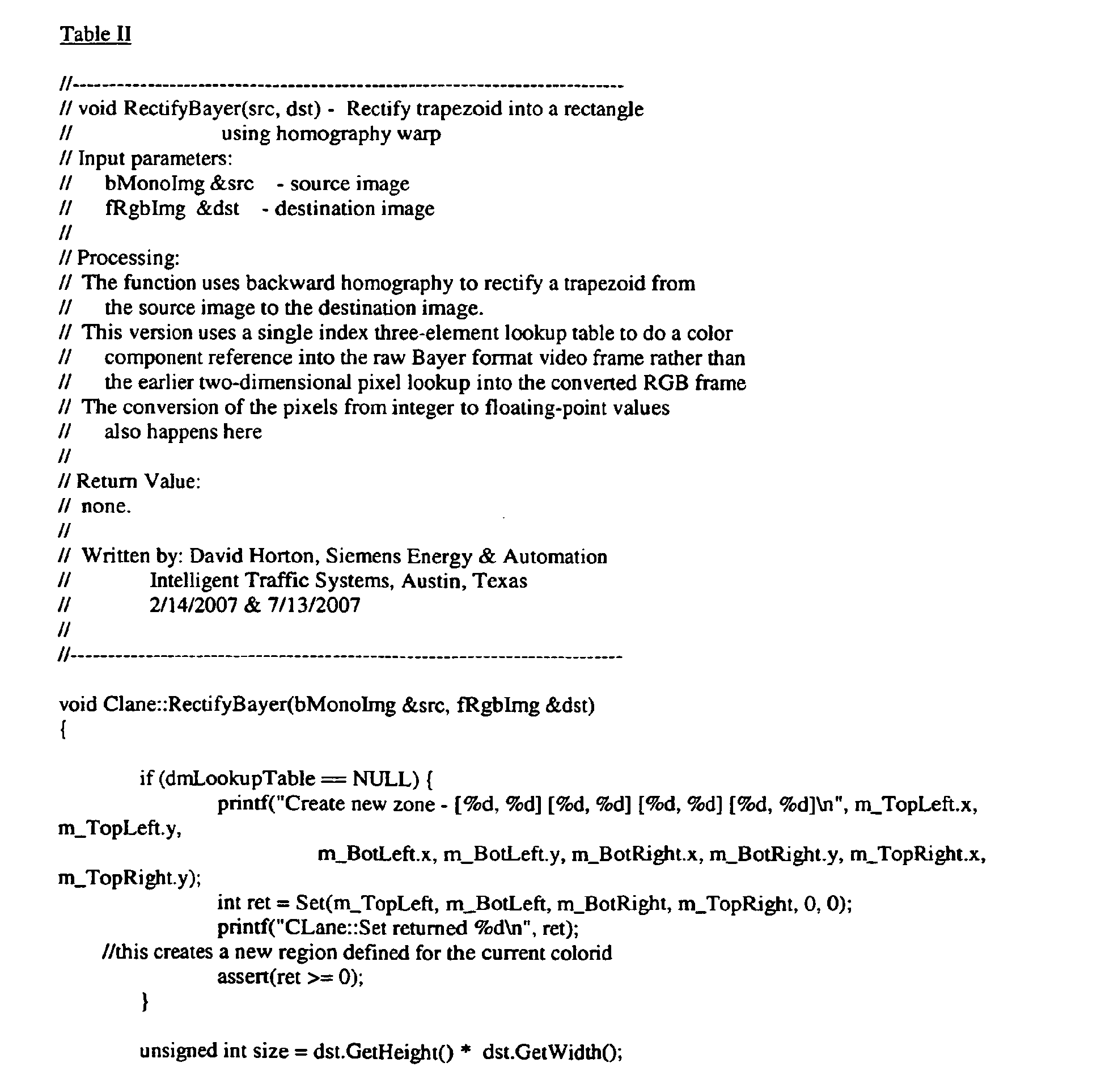
- Table II shows software code for generating a detection block using the look up table 148.
Landscapes
- Physics & Mathematics (AREA)
- General Physics & Mathematics (AREA)
- Engineering & Computer Science (AREA)
- Theoretical Computer Science (AREA)
- Image Processing (AREA)
- Color Television Systems (AREA)
- Ultra Sonic Daignosis Equipment (AREA)
- Editing Of Facsimile Originals (AREA)
Abstract
Description
- The present invention relates generally to image capture and detection systems, and more particularly to methods and arrangements for obtaining image data.
- It is increasingly desirable to employ vehicle detection in traffic control systems. Detection of the presence and/or approach of vehicles allows for improved efficiency in traffic control. In a simplified example, a traffic signal may not change to green for a cross street for an indefinite time if there are no vehicles present on the cross street awaiting the signal. However, if a vehicle approaches the intersection on the cross street, the traffic signal may be changed responsive to the detection of such approach.
- Historically, vehicle detection for traffic control has employed inductive sensors located under the road surface. The entrance of the automobile into a region near the inductive sensor changes the sensed magnetic field, thus enabling detection of the vehicle. A drawback of these systems is the need to implant the inductive sensors under or in the road surface pavement, which requires significant labor and traffic interruption. Because video cameras avoid the need to implant equipment below the road surface, camera-based vehicle detection systems are increasingly desirable.
- Camera-based vehicle detection systems using video processing are known. One type of vehicle detection system performs vehicle detection on select areas of available video frames provided by a video camera. To this end, a video camera provides video frame information, typically in a format known as the Bayer format, to a processing system. The processing system converts the Bayer formatted video to (red-green-blue) RGB formatted video, which is (or is similar to) the format employed by most digital video systems.
- The RGB formatted video is then provided to the detection subsystem and optionally to a viewing device, such as a remotely located laptop or portable computer. The detection subsystem then employs homographic mapping to isolate specific, select areas of the video frame for the actual detection algorithms. In particular, vehicle detection typically does not occur within an entire video frame, but rather in isolated areas such as portions of a road or near specific objects. The desired areas for detection are then converted into detection blocks that are standardized for the detection algorithms.
- Thus, for example, a small trapezoidal area of interest in or near an intersection is converted into a rectangle of a size and orientation that is suitable for the detection algorithms.
- Accordingly, the portion of the video image that is to be analyzed is stored as a detection block. The video data corresponding to the area of interest is transferred into the detection block via homographic mapping or warping. The detection block thus represents video data from the select area of interest.
- The detection algorithms then operate with the detection blocks in order to identify whether moving objects are within the select area of interest. The detection operations include integration, autocorrelation, center of chromatic mass, background processing, among others to detect moving vehicles and/or any presence of vehicles.
- Algorithmic detection of vehicles using the above techniques consumes a large amount of computational processing power. The processing engines that are commonly available in the wider temperature range are quite limited in the maximum processing speed available. Executing the necessary video processing for vehicle detection can cause such processors to run "too hot".
- There is a need therefore, for improved video processing that provides advanced detection needs within a limited processing power budget.
- Disclosed are apparatus and methods that employ image processing and which at least in some embodiments address the above-mentioned drawbacks of the prior art.
- The invention is defined by the appended claims.
- The features and advantages of the above-described embodiment, as well as others, will become more readily apparent to those of ordinary skill in the art by reference to the following detailed description and accompanying drawings.
-
-
Fig. 1 shows a schematic block diagram of a system for image processing that includes at least one embodiment of the invention; -
Fig. 2 shows a representative schematic diagram of a camera and an image frame; -
Fig. 3 shows a representation of two dimensional views of the image frame ofFig. 3 and corresponding detection blocks; -
Fig. 4 shows a diagram of aportion 402 of a video frame in mosaiced format; -
Fig. 5 shows a flow diagram of an exemplary set of operations that may be used to generate a detection block from a select video block of video frame data that is in mosaiced format; -
Fig. 6 shows a flow diagram of an exemplary operation that may be used to generate a look-up table in accordance with at least some embodiments of the invention; and -
Fig. 7 shows a more detailed schematic block diagram of an exemplary embodiment of the image processing system ofFig. 1 . -
Fig. 1 shows a block diagram of asystem 100 for image processing that includes at least one embodiment of the invention. Thesystem 100 includes a source ofvideo frame data 102, avehicle detection arrangement 104 and at least oneremote user interface 106. - The source of
video frame data 102 is a device or set of devices that is configured to provide video frame data in a first format. The first format of video frame data includes a plurality of pixels, each pixel containing single color data. By way of example, the source ofvideo frame data 102 is a digital camera or digital video camera that employs a high-speed CCD (Charge-Coupled Device) or CMOS (Complementary-Metal-Oxide-Semiconductor) light-sensitive imager arrays as an initial sensor. This array outputs data values corresponding to individual pixels (individual small picture elements) according to how much light intensity is measured at that particular pixel within the imager array. Such devices are well-known. - The first format of the video frame data may suitably comprise a mosaic formatted data. In particular, many video cameras are configured to generate mosaiced pixel data, sometimes referred to as Bayer-formatted data. Bayer format cameras typically includes a color mosaic lens positioned in front of an array of monochrome CCD detectors, and transmit the luminance value for each element instead of the individual color components.
Fig. 7 , discussed further below, shows an exemplary embodiment that employs amosaic lens camera 130. - Such a source effectively transmits only one color component value per pixel, and for each four pixels transferred, two are green pixels, one is a blue pixel, and one is a red pixel. As a result, green-spectrum video information is effectively subsampled at 50% resolution, while red and blue information is each effectively subsampled at 25% resolution. In any event, the frame data includes a plurality of pixels having only single-color information.
- In the interest of further explanation of mosaic formatted data,
Fig. 4 shows a diagram of aportion 402 of a video frame in single color or mosaiced format. Theportion 402 includes a mosaic of single color red, blue andgreen pixels - Implementation of the invention is not limited to the particular single color mosaic formats shown in
Fig. 4 . At least some embodiments of the invention are compatible with each of the four possible Bayer formats, and can readily be adapted to other similar subsampling mosaic patterns. - Returning again to
Fig. 1 , the source ofvideo frame data 102 is operably coupled to provide the video frame data in the first format to each of thevideo detection arrangement 104 and theremote user interface 106. - The
video detection arrangement 104 includes data processing equipment and associated circuitry that is capable of performing image processing as described herein. Thevideo detection arrangement 104 is configured to employ homographic mapping to generate a detection block from the video frame data. In this embodiment, the detection block is representative of a select subset of the video frame image, and typically includes a portion of the image that has been preselected as potentially containing vehicles to be detected. Homographic mapping (or warping) is employed to generate a re-aligned view, for example, a rectangle generated from a trapezoid, such that angled points of view are rectified into a normal (i.e perpendicular) point of view which aids the detection algorithms. - In an alternative application, a vehicle detection system may be used in a security system or other surveillance system that employs rotating cameras. In such a case, homographic mapping allows various points of view from a moving (e.g. rotating) camera to be compared and processed from the same point of view. In this alternative embodiment, the vehicle detection system may be connected to receive the video frame data from cameras used for general surveillance. General surveillance cameras often are configured to rotate to cover more area.
- Referring again to
Fig. 1 , the source ofvideo data 102 in this embodiment is typically a stationary image capturing device. In this case, the homographic mapping is used to map select portions (and non-standard shapes) of video data into a detection block. The detection block has a size and shape (square or rectangular) that is compatible with the detection algorithms. The select portion of the video data is often user selected and will often have at least some dimensions (size, shape) that differ from that of the detection block, and typically is significantly larger. - For example,
Figs. 2 and 3 illustrate by way of example how homographic mapping is employed to generate consistent, normalized representations of select (and variably shaped and sized) portions of a video frame image.Fig. 2 shows a camera 202 (which may suitably be used as the source ofvideo information 102 ofFig. 1 ), and animage frame 204. Theimage frame 204 consists of the two dimensional field of vision of thecamera 202. In this example, a user has defined two areas ofinterest interest Fig. 2 , the areas ofinterest image frame 204, have different shapes, and have different sizes. -
Fig. 3 shows a representation of two dimensional views of theimage frame 204, the areas of interest orimage portions image portions - Referring again to
Fig. 1 , thevehicle detection system 104 is thus configured to perform homographic mapping of an image of interest from each video frame received from thevideo camera 202, even though the video frame data remains in single color format. Thevehicle detection system 104 is further configured convert the single color format pixels of the input video to multiple color pixels (e.g. red, green, blue) of the detection block. - To this end, the
vehicle detection system 104 associates each pixel of the detection block with the pixel data of multiple pixels from the video frame data. Each pixel of the detection block is associated with pixel data of multiple pixels with different color data, such that each pixel of the detection block has information representative of multiple colors. Referring toFig. 4 , for example, a single pixel of the detection block may contain information from each of ared pixel 404, ablue pixel 406 and agreen pixel 408. - In any event, the resulting detection block thus only contains information from a small subset of the original video frame, and contains pixels that have been converted or demosaiced to multiple color format.
- Thus, the
video detection arrangement 104 is configured to convert the single color format video data of a portion (and only a portion) of the original video frame data that corresponds to the detection block into multi-color formatted video data. - In contrast to the prior art, the
video detection arrangement 104 only performs demosaicing of the portion of video frame data that corresponds to the select detection block, instead of the entire video frame. This saves computational power as the interpolation schemes used for demosaicing are computationally intensive. - Referring again generally to
Fig. 1 , thevideo detection arrangement 104 is further configured to perform vehicle detection algorithms on one or more detection blocks generated as described above. Vehicle detection in a video block may be accomplished using various techniques that are known in the art, such as integration, autocorrelation, center of chromatic mass, background processing and the like. - As discussed above, the
remote user interface 106 is also configured to received the video frame data in the first format. Theremote user interface 106 may suitably be a general purpose or special purpose computing device. Theremote user interface 106 is configured to perform demosaicing (conversion between single color pixel data of different colors to multiple color pixel data) on the entire image frame of the video frame data and display the frame data on video screen or display. Further detail regarding the demosaicing by theuser interface 106 is provided below in connection withFig. 7 . - Thus, the above described
image processing system 100 provides data that may be used for both viewing (via the user interface 106) and vehicle detection (via the vehicle detection arrangement 104) while reducing the computational load in the vehicle detection processing circuitry. -
Fig. 7 shows a more detailed schematic block diagram of an exemplary embodiment of theimage processing system 100 ofFig. 1 . - In the embodiment of
Fig. 7 , the source ofvideo frame data 102 is adigital camera 130 or digital video recorder that employs anarray 132 of high-speed monochrome CCD detectors. Thisarray 132 outputs data values corresponding to individual pixels (individual small picture elements) according to how much light intensity is measured at that particular pixel within theimager array 132. Thecamera 130 typically also includes acolor mosaic lens 134 positioned in front of thearray 132. Thecolor mosaic lens 134, as is known in the art, filters light such that the luminance value for each pixel represents intensity of a specific individual color component. The output of thecamera 130 may suitably be a Bayer formatted data such as shown inFig. 4 , and generally described inU.S. Patent No. 3,971,065 , which is incorporated by reference. As withFig. 1 , the output data of thecamera 130 is referred to as video frame data in the first format. Each set of video frame data consists of a single video frame, which is a still image. - The
camera 130 is operably coupled to provide the video frame data in the first format to each of thevideo detection arrangement 104 and theremote user interface 106. - The
video detection arrangement 104 includesprocessing circuitry 138 including at least onememory 136 and associated circuitry that is capable of carrying out thesteps processing circuitry 138 is configured to receive the video frame data in the first format and generate (step 140) pixel data of a detection block representative of a subset of the video frame data in which detection of images is to be performed. To generate the detection block, theprocessing circuitry 138 uses a look-up table 148 (stored in the memory 136) to associate pixel data of multiple pixels of the single color video frame data to each pixel of the detection block. - The generated detection block thus comprises pixel data representative of a select portion of the input video image data. The pixel data for each pixel of the generated detection block has multiple color components.
Fig. 5 , discussed below, provides an exemplary set of steps that carry out the function ofstep 140 described above. - The
processing circuitry 138 is further operable to perform image detection. In particular, instep 142, the processing circuitry performs vehicle detection algorithms on one or more detection blocks generated as described above. Vehicle detection in a video block may be accomplished using various techniques that are known in the art, such as integration, autocorrelation, center of chromatic mass, background processing and the like. Such detection techniques vary and would be known to those of ordinary skill in the art. - Thereafter, in
step 144, theprocessing circuitry 138 performs control based on the image detection. By way of example, a traffic signal operation may be altered as a result of a detection of the presence of a vehicle in one or more of the detection blocks generated instep 140. In another example, the absence of movement in one or more monitored areas may result in alteration of the traffic signal operation. Various traffic control methods based on detected vehicle presence or movement are known. - In order to perform the
above steps processing circuitry 138 is operable to generate the look-up table 148 used for this detection block generation. In particular, theprocessing circuit 138 may suitably receive input identifying select portions of an image (e.g. image portions Fig. 2 ) in which image detection is to take place viastep 142. The image portion may have a square, rectangular, trapezoidal, parallelogram, or other shape, and may be of various sizes and locations with the video frame. The input may be received from theuser interface 106. - The
processing circuit 138 then uses homographic mapping, among other things, to create a look-up table that associates each pixel of a detection block with multiple single color pixels of an input video frame that correspond to the user-selected image portion. The multiple single color pixels preferably include different color pixels of the input video frame such that each pixel of the detection block can have multiple color information.Fig. 6 , discussed further below, shows an exemplary operation in which such a look-up table 148 may be generated. - Referring again to
Fig. 7 , as discussed above, theremote user interface 106 is also configured to receive the video frame data in the first format. Theremote user interface 106 in this embodiment is a portable (e.g. "laptop") computer that is operably coupled to both thecamera 130 and theprocessing circuit 138. Thecomputer 106 is configured and/or programmed to perform the steps described herein. Thecomputer 106 is largely used for set-up and maintenance of thecamera 130 and/or theprocessing circuit 138, and thus is not necessarily permanently affixed to thesystem 100. - As discussed above in connection with
Fig. 1 , the remote user interface/computer 106 is configured to perform demosaicing (conversion between single color pixel data of different colors to multiple color pixel data) on the entire image frame of the video frame data and display the frame data on video screen or display. The frame rate of display at thecomputer 106 may suitably be as low as 100 images per minute, which allows for the demosaicing process in normal personal computing devices. - Various demosaicing operations are known, including nearest-neighbor interpolation, as a linear interpolation, as a bilinear interpolation, as a cubic spline interpolation, or as a different type of spline interpolation, typically with better visual quality yielded by the more complex interpolations. In some embodiments, the
computer 106 is configurable to select from a plurality of demosaicing operations, as well as frame rates so that the balance between frame rate, accuracy and complexity, and available computer processing power at the user interface/computer 106 can be selectively adjusted. - As discussed above, during normal operation of a configured system, the look-up tables 148 for one or more user-selected image portions have already been generated and stored in the
memory 136. The normal operation consists ofsteps - With regard to step 140,
Fig. 5 shows in further detail the operations that are used to generate a detection block from a select video block of video frame data that is in mosaiced format. - In
step 502, the video frame data in the first format is received from the source ofvideo frame data 102. As discussed above, the video frame data is in single color (mosaiced) format. -
Steps 504 to 510 represent a for-next loop that indexes through each pixel of the detection block. Thus, instep 504, the next pixel of the detection block is indexed. This is referred to herebelow as the current pixel. - In
step 506, the location of the current pixel within the detection block is indexed to the look-up table 148. As discussed above, the look-up table 148 associates each pixel of the detection block with a plurality of pixels within the video frame data. This plurality of pixels preferably includes at least one green pixel, at least one blue pixel and at least one red pixel of the mosaiced video frame data. Instep 508, the pixel data of the pixels of the video frame data associated with the current pixel is obtained form the video frame data and stored as the pixel data for the current pixel of the detection block. - In
step 510, it is determined whether there are additional pixels in the image block. If so, then the next pixel is identified instep 504 and the process is repeated accordingly. If not, then the entire detection block has been created, and step 512 is executed. Instep 512, the detection block is stored in memory, not shown, for use by theimage detection operations 142. - The above operations represent an improvement over the prior art in that the detection arrangement need not demosaic an entire video frame. Only a select portion of the video frame data is effective demosaiced. In this embodiment, a look-up table 148 is used to generate each pixel of the detection block from different colored pixels of the mosaiced video frame data. The look-up table 148 further accomplishes the homographic mapping because the selection of the location of pixels of the video frame data correspond to the pixels of the detection block are identified via homographic mapping. Thus, the development of a suitable look-up table is required to carry out the above-described operations.
- Accordingly,
Fig. 6 shows an exemplary set of operations that may be used to develop a look-up table that is used to carry outstep 506 ofFig. 5 and step 140 ofFig. 7 . In particular,Fig. 6 shows in detail a set of operations that carry outstep 146 ofFig. 7 . In addition, the software table provided below includes code for developing the look-up table. In this embodiment, the look-up table 148 is generated by theprocessing circuit 138 of thedetection arrangement 104. In other embodiments, the processing equipment in theuser interface 106 may perform the steps ofFig. 6 to generate the look-up table 148, which would then be transferred and stored in thememory 148. Nevertheless, in the present embodiment, the operations ofFig. 6 are carried out by theprocessing circuit 138 of theimage detection arrangement 104. - In
step 602, theprocessing circuit 138 receives input defining a block of a video frame image that is to be mapped into a detection block. Such a block of video frame image constitutes a portion of the image field of the camera in which vehicle location or presence is to be detected and/or monitored. For example, theprocessing circuit 138 may receive from theuser interface 106 information identifying image portions imageportions 206 and/or 208 (seeFigs. 2 and 3 ) for monitoring. Theprocessing circuit 138 receives the information identifying the select image portions in any suitable manner, such as by identification of the corner pixels of the image portion. - It is noted that the user may define multiple image portions, such as the
portions Figs. 2 and 3 , for monitoring.Steps 604 to 616 ofFig. 6 are performed separately for each identified image portion. Thus, for example, ifimage portions Figs. 2 and 3 are selected by the user, steps 604-616 are performed to prepare a look-up table forportion 206, and steps 604-616 are also performed to prepare a separate look-up table forportion 208. - As an
initial step 604, homographic mapping equations are solved for the selected image portion and the detection block. Homographic mapping equations associate the detection block (e.g. the block 210), with a portion of an image frame (e.g. portion 206 ofFig. 3 ). The detection block and the selected image portion typically have a different size and/or shape. The selected image portion is also embedded within a larger video frame (e.g. frame 204 ofFig. 3 ), whereas the detection block is not. Solving such homographic equations involves in this case eight unknowns and eight equations. Such homographic equations and their solutions are known, and an example is provided in the attached software code. - The resulting homographic equations help provide a translation from a location in the detection block to a location in the video image data.
- In
steps 606 to 614, the look-up table 148 is populated on a pixel-by-pixel basis, using the homography solution fromstep 604. - In
step 606, the next pixel in the detection block is indexed. This pixel is referred to below as the current pixel. Instep 608, theprocessing circuitry 138 uses the homography solution fromstep 604 to associate the current pixel with a pixel of the video frame within the selected image portion. Thus, for example, if the current pixel is the upper left corner of the detection block, then homographysolution 604 would likely associate the current pixel with the upper left hand corner of the selected image portion. - As a result, the homography solution is used in
step 608 to identify a pixel of the video frame (within the selected image portion) that corresponds to the current pixel. This identified pixel is referred to as the corresponding pixel. The corresponding pixel in each set of video frame data will contain pixel data having single color information. - In
step 610, theprocessing circuitry 138 identifies and selects neighboring pixels that are configured to have other single colors. For example, if the corresponding pixel is a red pixel, then the processor instep 610 identifies neighboring blue and green pixels. Thus, the corresponding pixel and the neighboring pixels should include information for all of the pixel colors of the output video image data format. - Preferably, the two neighboring pixels are selected such that they include at least one pixel from a different horizontal line such that the corresponding pixel and the two neighboring pixels form a cluster. For example, referring to
Fig. 4 , if the corresponding pixel is determined instep 608 to be thegreen pixel 408, then the processor may suitably select thered pixel 404 and theblue pixel 406 as the neighboring pixels. It is noted that in Bayer formatted mosaiced data (see e.g.,Fig. 4 ), pixel data from at least two lines is necessary to obtain representation from all available pixel colors. - In
step 612, the table entry for the current pixel is created. The table entry identifies the locations of the corresponding pixel determined instep 608 and the neighboring pixels determined instep 610. Afterstep 612, the look-up table 148 has been populated for at least the current pixel. In this embodiment, the look-up table 148 identifies three single color pixels of the input video frame data that are used to form the current pixel of the detection block. - In
step 614, the processor determines whether a table entry must be determined for any more pixels in the detection block. If so, then the processor returns to step 606 to process the next pixel of the detection block. If not, however, then the processor proceeds to step 616. - In
step 616, the processor has completed the look-up table creation operation. The look-up table 148 now provides a translation from a mosaiced image block having a first set of dimensions to a demosaiced image block (the detection block) having a second set of dimensions, including a preferred square or rectangular shape. - Table I shows exemplary software code used for generating the look up table 148. Table II shows software code for generating a detection block using the look up table 148.


- It will be understood that the above describe embodiments are merely exemplary, and that the scope of the invention is limited by the scope of the appended claims only.
Claims (10)
- A method for detecting an object in an image, said method comprising:a) capturing the image;b) providing single color video frame data of the image in a first format that includes pixel data for a plurality pixels, the pixel data of each image pixel consisting of single color data;c) generating multiple color pixel data for each pixel of a detection block representative of an image portion which is a subset of the single color video frame data and which is homographically associated to said detection block, wherein the multiple color pixel data of each pixel of the detection block is generated from single color pixel data of image portion pixels identified using said homographic association;d) providing the generated multiple color pixel data of the detection block to an object detection algorithm adapted to detect an object inside the detection block.
- The method of claim 1, wherein step c) further comprises associating each pixel of the detection block with the pixel data of multiple pixels having single color data representative of multiple colors.
- The method of claim 1, wherein step c) further comprises associating each pixel of the detection block with the pixel data of three contiguous pixels of the subset of video frame data.
- The method of claim 1, wherein step d) further comprises providing the detection block such that each pixel includes red, green and blue color data.
- The method of claim 1, further comprising:e) providing the video frame data in the first format to a computing device;f) employing the computing device to demosaic frames of video frame data in the first format to generate demosaiced frame video data.
- The method of claim 1, wherein step a) further comprises employing a digital camera that employs a mosaic lens.
- An arrangement for detecting an object in an image, said arrangement comprising:a camera arrangement configured to capture an image and provide single color video frame data of the image in a first format that includes pixel data for a plurality pixels, the pixel data of each pixel consisting of single color data;a processing circuit configured to
generate multiple color pixel data for each pixel of a detection block representative of an image portion which is a subset of the single color video frame data and which is homographically associated to said detection block, wherein the multiple color pixel data of each pixel of the detection block is generated from single color pixel data of image portion pixels identified using said homographic association;
provide the generated multiple color pixel data of the detection block to an object detection algorithm adapted to detect an object inside the detection block. - The arrangement of claim 7, wherein the camera arrangement further comprises a CCD camera and a mosaic lens.
- The arrangement of claim 7, wherein the processing circuit is further configured to associate each pixel of the detection block with the pixel data of multiple pixels having single color data representative of multiple colors.
- The arrangement of claim 7, wherein the processing circuit is further configured to associating each pixel of the detection block with the pixel data of three contiguous pixels of the subset of video frame data.
Applications Claiming Priority (2)
| Application Number | Priority Date | Filing Date | Title |
|---|---|---|---|
| US94806907P | 2007-07-05 | 2007-07-05 | |
| PCT/US2008/008325 WO2009009024A2 (en) | 2007-07-05 | 2008-07-07 | Arrangement and method for procesing image data |
Publications (2)
| Publication Number | Publication Date |
|---|---|
| EP2176829A2 EP2176829A2 (en) | 2010-04-21 |
| EP2176829B1 true EP2176829B1 (en) | 2010-12-01 |
Family
ID=40042737
Family Applications (1)
| Application Number | Title | Priority Date | Filing Date |
|---|---|---|---|
| EP08826248A Not-in-force EP2176829B1 (en) | 2007-07-05 | 2008-07-07 | Arrangement and method for processing image data |
Country Status (7)
| Country | Link |
|---|---|
| US (1) | US20090015713A1 (en) |
| EP (1) | EP2176829B1 (en) |
| CN (1) | CN101796542A (en) |
| AT (1) | ATE490519T1 (en) |
| DE (1) | DE602008003837D1 (en) |
| ES (1) | ES2357371T3 (en) |
| WO (1) | WO2009009024A2 (en) |
Families Citing this family (5)
| Publication number | Priority date | Publication date | Assignee | Title |
|---|---|---|---|---|
| BR112014009342A2 (en) * | 2011-10-20 | 2017-04-18 | Koninklijke Philips Nv | system; workstation for functional cardiac assessment; and method |
| WO2013101211A1 (en) | 2011-12-30 | 2013-07-04 | Intel Corporation | User interfaces for electronic devices |
| US8817179B2 (en) * | 2013-01-08 | 2014-08-26 | Microsoft Corporation | Chroma frame conversion for the video codec |
| US9349288B2 (en) | 2014-07-28 | 2016-05-24 | Econolite Group, Inc. | Self-configuring traffic signal controller |
| CN110322405B (en) * | 2019-07-16 | 2023-07-25 | 广东工业大学 | Video demosaicing method and related device based on self-encoder |
Family Cites Families (6)
| Publication number | Priority date | Publication date | Assignee | Title |
|---|---|---|---|---|
| US6404918B1 (en) * | 1999-04-30 | 2002-06-11 | Hewlett-Packard Company | Image demosaicing method utilizing directional smoothing |
| US6989862B2 (en) * | 2001-08-23 | 2006-01-24 | Agilent Technologies, Inc. | System and method for concurrently demosaicing and resizing raw data images |
| US7003150B2 (en) * | 2001-11-05 | 2006-02-21 | Koninklijke Philips Electronics N.V. | Homography transfer from point matches |
| JP2004198211A (en) * | 2002-12-18 | 2004-07-15 | Aisin Seiki Co Ltd | Apparatus for monitoring vicinity of mobile object |
| US6879731B2 (en) * | 2003-04-29 | 2005-04-12 | Microsoft Corporation | System and process for generating high dynamic range video |
| US7884849B2 (en) * | 2005-09-26 | 2011-02-08 | Objectvideo, Inc. | Video surveillance system with omni-directional camera |
-
2008
- 2008-07-07 ES ES08826248T patent/ES2357371T3/en active Active
- 2008-07-07 DE DE602008003837T patent/DE602008003837D1/en active Active
- 2008-07-07 CN CN200880105809A patent/CN101796542A/en active Pending
- 2008-07-07 EP EP08826248A patent/EP2176829B1/en not_active Not-in-force
- 2008-07-07 US US12/217,615 patent/US20090015713A1/en not_active Abandoned
- 2008-07-07 AT AT08826248T patent/ATE490519T1/en not_active IP Right Cessation
- 2008-07-07 WO PCT/US2008/008325 patent/WO2009009024A2/en active Application Filing
Also Published As
| Publication number | Publication date |
|---|---|
| WO2009009024A2 (en) | 2009-01-15 |
| WO2009009024A3 (en) | 2009-02-26 |
| ATE490519T1 (en) | 2010-12-15 |
| EP2176829A2 (en) | 2010-04-21 |
| DE602008003837D1 (en) | 2011-01-13 |
| US20090015713A1 (en) | 2009-01-15 |
| ES2357371T3 (en) | 2011-04-25 |
| CN101796542A (en) | 2010-08-04 |
Similar Documents
| Publication | Publication Date | Title |
|---|---|---|
| JP5461568B2 (en) | Modify color and full color channel CFA images | |
| CN109377469B (en) | Processing method, system and storage medium for fusing thermal imaging with visible light image | |
| EP2589226B1 (en) | Image capture using luminance and chrominance sensors | |
| TWI467495B (en) | Edge mapping using panchromatic pixels | |
| US20050128509A1 (en) | Image creating method and imaging device | |
| TWI430184B (en) | Edge mapping incorporating panchromatic pixels | |
| US20140340515A1 (en) | Image processing method and system | |
| US20050099516A1 (en) | Error calibration for digital image sensors and apparatus using the same | |
| US7148924B2 (en) | Image processing method, image processing program, image processing apparatus, and digital still camera using the image processing apparatus | |
| JP4747970B2 (en) | Image processing device | |
| JPH07264606A (en) | Cfa-compatible electronic camera having reduced resolution and single sensor | |
| JP2010088105A (en) | Imaging apparatus and method, and program | |
| CN111837155A (en) | Image processing method and apparatus | |
| JP2007074578A (en) | Image processor, photography instrument, and program | |
| EP2176829B1 (en) | Arrangement and method for processing image data | |
| JP2023075366A (en) | Information processing apparatus, recognition support method, and computer program | |
| US11587259B2 (en) | Fixed pattern calibration for multi-view stitching | |
| JP6259188B2 (en) | Image processing apparatus and method | |
| US20110141321A1 (en) | Method and apparatus for transforming a lens-distorted image to a perspective image in bayer space | |
| US20070253626A1 (en) | Resizing Raw Image Data Before Storing The Data | |
| JP5395650B2 (en) | Subject area extraction device and control method thereof, subject tracking device, and program | |
| JP4682782B2 (en) | Image processing device | |
| JP5733588B2 (en) | Image processing apparatus and method, and program | |
| US20100110210A1 (en) | Method and means of recording format independent cropping information | |
| JP5883715B2 (en) | Image processing LSI, image processing system, and image processing method |
Legal Events
| Date | Code | Title | Description |
|---|---|---|---|
| PUAI | Public reference made under article 153(3) epc to a published international application that has entered the european phase |
Free format text: ORIGINAL CODE: 0009012 |
|
| 17P | Request for examination filed |
Effective date: 20100118 |
|
| AK | Designated contracting states |
Kind code of ref document: A2 Designated state(s): AT BE BG CH CY CZ DE DK EE ES FI FR GB GR HR HU IE IS IT LI LT LU LV MC MT NL NO PL PT RO SE SI SK TR |
|
| AX | Request for extension of the european patent |
Extension state: AL BA MK RS |
|
| GRAP | Despatch of communication of intention to grant a patent |
Free format text: ORIGINAL CODE: EPIDOSNIGR1 |
|
| RTI1 | Title (correction) |
Free format text: ARRANGEMENT AND METHOD FOR PROCESSING IMAGE DATA |
|
| GRAS | Grant fee paid |
Free format text: ORIGINAL CODE: EPIDOSNIGR3 |
|
| GRAA | (expected) grant |
Free format text: ORIGINAL CODE: 0009210 |
|
| AK | Designated contracting states |
Kind code of ref document: B1 Designated state(s): AT BE BG CH CY CZ DE DK EE ES FI FR GB GR HR HU IE IS IT LI LT LU LV MC MT NL NO PL PT RO SE SI SK TR |
|
| REG | Reference to a national code |
Ref country code: GB Ref legal event code: FG4D |
|
| REG | Reference to a national code |
Ref country code: CH Ref legal event code: EP |
|
| REG | Reference to a national code |
Ref country code: IE Ref legal event code: FG4D |
|
| REF | Corresponds to: |
Ref document number: 602008003837 Country of ref document: DE Date of ref document: 20110113 Kind code of ref document: P |
|
| REG | Reference to a national code |
Ref country code: NL Ref legal event code: T3 |
|
| REG | Reference to a national code |
Ref country code: ES Ref legal event code: FG2A Ref document number: 2357371 Country of ref document: ES Kind code of ref document: T3 Effective date: 20110425 |
|
| PG25 | Lapsed in a contracting state [announced via postgrant information from national office to epo] |
Ref country code: LT Free format text: LAPSE BECAUSE OF FAILURE TO SUBMIT A TRANSLATION OF THE DESCRIPTION OR TO PAY THE FEE WITHIN THE PRESCRIBED TIME-LIMIT Effective date: 20101201 Ref country code: NO Free format text: LAPSE BECAUSE OF FAILURE TO SUBMIT A TRANSLATION OF THE DESCRIPTION OR TO PAY THE FEE WITHIN THE PRESCRIBED TIME-LIMIT Effective date: 20110301 |
|
| LTIE | Lt: invalidation of european patent or patent extension |
Effective date: 20101201 |
|
| PG25 | Lapsed in a contracting state [announced via postgrant information from national office to epo] |
Ref country code: SE Free format text: LAPSE BECAUSE OF FAILURE TO SUBMIT A TRANSLATION OF THE DESCRIPTION OR TO PAY THE FEE WITHIN THE PRESCRIBED TIME-LIMIT Effective date: 20101201 Ref country code: AT Free format text: LAPSE BECAUSE OF FAILURE TO SUBMIT A TRANSLATION OF THE DESCRIPTION OR TO PAY THE FEE WITHIN THE PRESCRIBED TIME-LIMIT Effective date: 20101201 Ref country code: CY Free format text: LAPSE BECAUSE OF FAILURE TO SUBMIT A TRANSLATION OF THE DESCRIPTION OR TO PAY THE FEE WITHIN THE PRESCRIBED TIME-LIMIT Effective date: 20101201 Ref country code: BG Free format text: LAPSE BECAUSE OF FAILURE TO SUBMIT A TRANSLATION OF THE DESCRIPTION OR TO PAY THE FEE WITHIN THE PRESCRIBED TIME-LIMIT Effective date: 20110301 Ref country code: FI Free format text: LAPSE BECAUSE OF FAILURE TO SUBMIT A TRANSLATION OF THE DESCRIPTION OR TO PAY THE FEE WITHIN THE PRESCRIBED TIME-LIMIT Effective date: 20101201 Ref country code: HR Free format text: LAPSE BECAUSE OF FAILURE TO SUBMIT A TRANSLATION OF THE DESCRIPTION OR TO PAY THE FEE WITHIN THE PRESCRIBED TIME-LIMIT Effective date: 20101201 Ref country code: LV Free format text: LAPSE BECAUSE OF FAILURE TO SUBMIT A TRANSLATION OF THE DESCRIPTION OR TO PAY THE FEE WITHIN THE PRESCRIBED TIME-LIMIT Effective date: 20101201 Ref country code: SI Free format text: LAPSE BECAUSE OF FAILURE TO SUBMIT A TRANSLATION OF THE DESCRIPTION OR TO PAY THE FEE WITHIN THE PRESCRIBED TIME-LIMIT Effective date: 20101201 |
|
| PG25 | Lapsed in a contracting state [announced via postgrant information from national office to epo] |
Ref country code: GR Free format text: LAPSE BECAUSE OF FAILURE TO SUBMIT A TRANSLATION OF THE DESCRIPTION OR TO PAY THE FEE WITHIN THE PRESCRIBED TIME-LIMIT Effective date: 20110302 |
|
| PG25 | Lapsed in a contracting state [announced via postgrant information from national office to epo] |
Ref country code: PT Free format text: LAPSE BECAUSE OF FAILURE TO SUBMIT A TRANSLATION OF THE DESCRIPTION OR TO PAY THE FEE WITHIN THE PRESCRIBED TIME-LIMIT Effective date: 20110401 Ref country code: CZ Free format text: LAPSE BECAUSE OF FAILURE TO SUBMIT A TRANSLATION OF THE DESCRIPTION OR TO PAY THE FEE WITHIN THE PRESCRIBED TIME-LIMIT Effective date: 20101201 Ref country code: IS Free format text: LAPSE BECAUSE OF FAILURE TO SUBMIT A TRANSLATION OF THE DESCRIPTION OR TO PAY THE FEE WITHIN THE PRESCRIBED TIME-LIMIT Effective date: 20110401 Ref country code: BE Free format text: LAPSE BECAUSE OF FAILURE TO SUBMIT A TRANSLATION OF THE DESCRIPTION OR TO PAY THE FEE WITHIN THE PRESCRIBED TIME-LIMIT Effective date: 20101201 Ref country code: EE Free format text: LAPSE BECAUSE OF FAILURE TO SUBMIT A TRANSLATION OF THE DESCRIPTION OR TO PAY THE FEE WITHIN THE PRESCRIBED TIME-LIMIT Effective date: 20101201 |
|
| PG25 | Lapsed in a contracting state [announced via postgrant information from national office to epo] |
Ref country code: SK Free format text: LAPSE BECAUSE OF FAILURE TO SUBMIT A TRANSLATION OF THE DESCRIPTION OR TO PAY THE FEE WITHIN THE PRESCRIBED TIME-LIMIT Effective date: 20101201 Ref country code: PL Free format text: LAPSE BECAUSE OF FAILURE TO SUBMIT A TRANSLATION OF THE DESCRIPTION OR TO PAY THE FEE WITHIN THE PRESCRIBED TIME-LIMIT Effective date: 20101201 Ref country code: RO Free format text: LAPSE BECAUSE OF FAILURE TO SUBMIT A TRANSLATION OF THE DESCRIPTION OR TO PAY THE FEE WITHIN THE PRESCRIBED TIME-LIMIT Effective date: 20101201 |
|
| PLBE | No opposition filed within time limit |
Free format text: ORIGINAL CODE: 0009261 |
|
| STAA | Information on the status of an ep patent application or granted ep patent |
Free format text: STATUS: NO OPPOSITION FILED WITHIN TIME LIMIT |
|
| PG25 | Lapsed in a contracting state [announced via postgrant information from national office to epo] |
Ref country code: DK Free format text: LAPSE BECAUSE OF FAILURE TO SUBMIT A TRANSLATION OF THE DESCRIPTION OR TO PAY THE FEE WITHIN THE PRESCRIBED TIME-LIMIT Effective date: 20101201 |
|
| PGFP | Annual fee paid to national office [announced via postgrant information from national office to epo] |
Ref country code: FR Payment date: 20110801 Year of fee payment: 4 |
|
| 26N | No opposition filed |
Effective date: 20110902 |
|
| PGFP | Annual fee paid to national office [announced via postgrant information from national office to epo] |
Ref country code: ES Payment date: 20110810 Year of fee payment: 4 Ref country code: DE Payment date: 20110919 Year of fee payment: 4 |
|
| REG | Reference to a national code |
Ref country code: DE Ref legal event code: R097 Ref document number: 602008003837 Country of ref document: DE Effective date: 20110902 |
|
| PG25 | Lapsed in a contracting state [announced via postgrant information from national office to epo] |
Ref country code: MT Free format text: LAPSE BECAUSE OF FAILURE TO SUBMIT A TRANSLATION OF THE DESCRIPTION OR TO PAY THE FEE WITHIN THE PRESCRIBED TIME-LIMIT Effective date: 20101201 |
|
| PGFP | Annual fee paid to national office [announced via postgrant information from national office to epo] |
Ref country code: NL Payment date: 20110714 Year of fee payment: 4 Ref country code: IT Payment date: 20110731 Year of fee payment: 4 |
|
| PG25 | Lapsed in a contracting state [announced via postgrant information from national office to epo] |
Ref country code: MC Free format text: LAPSE BECAUSE OF NON-PAYMENT OF DUE FEES Effective date: 20110731 |
|
| REG | Reference to a national code |
Ref country code: IE Ref legal event code: MM4A |
|
| PG25 | Lapsed in a contracting state [announced via postgrant information from national office to epo] |
Ref country code: IE Free format text: LAPSE BECAUSE OF NON-PAYMENT OF DUE FEES Effective date: 20110707 |
|
| REG | Reference to a national code |
Ref country code: NL Ref legal event code: V1 Effective date: 20130201 |
|
| REG | Reference to a national code |
Ref country code: CH Ref legal event code: PL |
|
| GBPC | Gb: european patent ceased through non-payment of renewal fee |
Effective date: 20120707 |
|
| REG | Reference to a national code |
Ref country code: FR Ref legal event code: ST Effective date: 20130329 |
|
| PG25 | Lapsed in a contracting state [announced via postgrant information from national office to epo] |
Ref country code: GB Free format text: LAPSE BECAUSE OF NON-PAYMENT OF DUE FEES Effective date: 20120707 Ref country code: CH Free format text: LAPSE BECAUSE OF NON-PAYMENT OF DUE FEES Effective date: 20120731 Ref country code: NL Free format text: LAPSE BECAUSE OF NON-PAYMENT OF DUE FEES Effective date: 20130201 Ref country code: DE Free format text: LAPSE BECAUSE OF NON-PAYMENT OF DUE FEES Effective date: 20130201 Ref country code: FR Free format text: LAPSE BECAUSE OF NON-PAYMENT OF DUE FEES Effective date: 20120731 Ref country code: LI Free format text: LAPSE BECAUSE OF NON-PAYMENT OF DUE FEES Effective date: 20120731 |
|
| REG | Reference to a national code |
Ref country code: DE Ref legal event code: R119 Ref document number: 602008003837 Country of ref document: DE Effective date: 20130201 |
|
| PG25 | Lapsed in a contracting state [announced via postgrant information from national office to epo] |
Ref country code: LU Free format text: LAPSE BECAUSE OF NON-PAYMENT OF DUE FEES Effective date: 20110707 Ref country code: IT Free format text: LAPSE BECAUSE OF NON-PAYMENT OF DUE FEES Effective date: 20120707 |
|
| PG25 | Lapsed in a contracting state [announced via postgrant information from national office to epo] |
Ref country code: TR Free format text: LAPSE BECAUSE OF FAILURE TO SUBMIT A TRANSLATION OF THE DESCRIPTION OR TO PAY THE FEE WITHIN THE PRESCRIBED TIME-LIMIT Effective date: 20101201 |
|
| REG | Reference to a national code |
Ref country code: ES Ref legal event code: FD2A Effective date: 20131021 |
|
| PG25 | Lapsed in a contracting state [announced via postgrant information from national office to epo] |
Ref country code: ES Free format text: LAPSE BECAUSE OF NON-PAYMENT OF DUE FEES Effective date: 20120708 Ref country code: HU Free format text: LAPSE BECAUSE OF FAILURE TO SUBMIT A TRANSLATION OF THE DESCRIPTION OR TO PAY THE FEE WITHIN THE PRESCRIBED TIME-LIMIT Effective date: 20101201 |