EP2176447B1 - A microporous layer for lowering friction in metal-forming processes - Google Patents
A microporous layer for lowering friction in metal-forming processes Download PDFInfo
- Publication number
- EP2176447B1 EP2176447B1 EP08758242.5A EP08758242A EP2176447B1 EP 2176447 B1 EP2176447 B1 EP 2176447B1 EP 08758242 A EP08758242 A EP 08758242A EP 2176447 B1 EP2176447 B1 EP 2176447B1
- Authority
- EP
- European Patent Office
- Prior art keywords
- microporous layer
- alloy
- friction
- metal
- substrate
- Prior art date
- Legal status (The legal status is an assumption and is not a legal conclusion. Google has not performed a legal analysis and makes no representation as to the accuracy of the status listed.)
- Not-in-force
Links
- 238000000034 method Methods 0.000 title claims abstract description 22
- 229910052751 metal Inorganic materials 0.000 claims abstract description 30
- 239000002184 metal Substances 0.000 claims abstract description 30
- 239000000314 lubricant Substances 0.000 claims abstract description 21
- 238000005461 lubrication Methods 0.000 claims abstract description 16
- 239000000758 substrate Substances 0.000 claims abstract description 14
- 150000002739 metals Chemical class 0.000 claims abstract description 8
- 238000003486 chemical etching Methods 0.000 claims abstract 3
- 229910045601 alloy Inorganic materials 0.000 claims description 28
- 239000000956 alloy Substances 0.000 claims description 28
- 238000000576 coating method Methods 0.000 claims description 22
- 229910005728 SnZn Inorganic materials 0.000 claims description 19
- 239000011248 coating agent Substances 0.000 claims description 19
- 238000005530 etching Methods 0.000 claims description 17
- 239000000203 mixture Substances 0.000 claims description 16
- RYGMFSIKBFXOCR-UHFFFAOYSA-N Copper Chemical compound [Cu] RYGMFSIKBFXOCR-UHFFFAOYSA-N 0.000 claims description 10
- VEXZGXHMUGYJMC-UHFFFAOYSA-N Hydrochloric acid Chemical compound Cl VEXZGXHMUGYJMC-UHFFFAOYSA-N 0.000 claims description 9
- 239000000243 solution Substances 0.000 claims description 7
- 239000000126 substance Substances 0.000 claims description 7
- 229910052802 copper Inorganic materials 0.000 claims description 6
- 239000010949 copper Substances 0.000 claims description 6
- 238000000151 deposition Methods 0.000 claims description 6
- 239000011148 porous material Substances 0.000 claims description 6
- 238000009713 electroplating Methods 0.000 claims description 5
- 239000002480 mineral oil Substances 0.000 claims description 4
- 235000010446 mineral oil Nutrition 0.000 claims description 4
- 239000006104 solid solution Substances 0.000 claims description 3
- -1 AgCu Inorganic materials 0.000 claims description 2
- 229910017727 AgNi Inorganic materials 0.000 claims description 2
- 229910015373 AuCo Inorganic materials 0.000 claims description 2
- 229910015371 AuCu Inorganic materials 0.000 claims description 2
- 229910002520 CoCu Inorganic materials 0.000 claims description 2
- 229910021118 PdCo Inorganic materials 0.000 claims description 2
- 150000007529 inorganic bases Chemical class 0.000 claims description 2
- 150000007522 mineralic acids Chemical class 0.000 claims description 2
- 239000003921 oil Substances 0.000 claims description 2
- 150000007524 organic acids Chemical class 0.000 claims description 2
- 150000007530 organic bases Chemical class 0.000 claims description 2
- 239000007788 liquid Substances 0.000 claims 1
- 239000011701 zinc Substances 0.000 description 15
- 238000012360 testing method Methods 0.000 description 12
- 238000013019 agitation Methods 0.000 description 8
- 229910052725 zinc Inorganic materials 0.000 description 8
- 230000001965 increasing effect Effects 0.000 description 7
- 239000000047 product Substances 0.000 description 7
- 238000007739 conversion coating Methods 0.000 description 6
- CWQXQMHSOZUFJS-UHFFFAOYSA-N molybdenum disulfide Chemical compound S=[Mo]=S CWQXQMHSOZUFJS-UHFFFAOYSA-N 0.000 description 6
- 229910000165 zinc phosphate Inorganic materials 0.000 description 6
- 229910019142 PO4 Inorganic materials 0.000 description 5
- 239000003792 electrolyte Substances 0.000 description 5
- XLYOFNOQVPJJNP-UHFFFAOYSA-N water Substances O XLYOFNOQVPJJNP-UHFFFAOYSA-N 0.000 description 5
- LRXTYHSAJDENHV-UHFFFAOYSA-H zinc phosphate Chemical group [Zn+2].[Zn+2].[Zn+2].[O-]P([O-])([O-])=O.[O-]P([O-])([O-])=O LRXTYHSAJDENHV-UHFFFAOYSA-H 0.000 description 5
- XEEYBQQBJWHFJM-UHFFFAOYSA-N iron Substances [Fe] XEEYBQQBJWHFJM-UHFFFAOYSA-N 0.000 description 4
- 229910052961 molybdenite Inorganic materials 0.000 description 4
- 229910052982 molybdenum disulfide Inorganic materials 0.000 description 4
- 239000000344 soap Substances 0.000 description 4
- 229910000838 Al alloy Inorganic materials 0.000 description 3
- NBIIXXVUZAFLBC-UHFFFAOYSA-N Phosphoric acid Chemical compound OP(O)(O)=O NBIIXXVUZAFLBC-UHFFFAOYSA-N 0.000 description 3
- 239000004411 aluminium Substances 0.000 description 3
- 229910052782 aluminium Inorganic materials 0.000 description 3
- XAGFODPZIPBFFR-UHFFFAOYSA-N aluminium Chemical compound [Al] XAGFODPZIPBFFR-UHFFFAOYSA-N 0.000 description 3
- 230000007423 decrease Effects 0.000 description 3
- 230000008021 deposition Effects 0.000 description 3
- 238000001125 extrusion Methods 0.000 description 3
- 238000009778 extrusion testing Methods 0.000 description 3
- 230000006870 function Effects 0.000 description 3
- 238000004519 manufacturing process Methods 0.000 description 3
- 239000010452 phosphate Substances 0.000 description 3
- NBIIXXVUZAFLBC-UHFFFAOYSA-K phosphate Chemical compound [O-]P([O-])([O-])=O NBIIXXVUZAFLBC-UHFFFAOYSA-K 0.000 description 3
- 239000011592 zinc chloride Substances 0.000 description 3
- JIAARYAFYJHUJI-UHFFFAOYSA-L zinc dichloride Chemical compound [Cl-].[Cl-].[Zn+2] JIAARYAFYJHUJI-UHFFFAOYSA-L 0.000 description 3
- KLZUFWVZNOTSEM-UHFFFAOYSA-K Aluminium flouride Chemical compound F[Al](F)F KLZUFWVZNOTSEM-UHFFFAOYSA-K 0.000 description 2
- ATJFFYVFTNAWJD-UHFFFAOYSA-N Tin Chemical compound [Sn] ATJFFYVFTNAWJD-UHFFFAOYSA-N 0.000 description 2
- KGBXLFKZBHKPEV-UHFFFAOYSA-N boric acid Chemical compound OB(O)O KGBXLFKZBHKPEV-UHFFFAOYSA-N 0.000 description 2
- 230000015556 catabolic process Effects 0.000 description 2
- 238000006243 chemical reaction Methods 0.000 description 2
- 238000004140 cleaning Methods 0.000 description 2
- 238000010273 cold forging Methods 0.000 description 2
- 238000012669 compression test Methods 0.000 description 2
- 150000002500 ions Chemical class 0.000 description 2
- 238000010409 ironing Methods 0.000 description 2
- 230000001050 lubricating effect Effects 0.000 description 2
- 239000010687 lubricating oil Substances 0.000 description 2
- 238000003760 magnetic stirring Methods 0.000 description 2
- 239000002245 particle Substances 0.000 description 2
- 238000005554 pickling Methods 0.000 description 2
- 239000007787 solid Substances 0.000 description 2
- 239000005069 Extreme pressure additive Substances 0.000 description 1
- UFHFLCQGNIYNRP-UHFFFAOYSA-N Hydrogen Chemical compound [H][H] UFHFLCQGNIYNRP-UHFFFAOYSA-N 0.000 description 1
- 229910000831 Steel Inorganic materials 0.000 description 1
- HCHKCACWOHOZIP-UHFFFAOYSA-N Zinc Chemical compound [Zn] HCHKCACWOHOZIP-UHFFFAOYSA-N 0.000 description 1
- 239000002253 acid Substances 0.000 description 1
- 239000003929 acidic solution Substances 0.000 description 1
- 239000012190 activator Substances 0.000 description 1
- 239000000654 additive Substances 0.000 description 1
- 239000012670 alkaline solution Substances 0.000 description 1
- 238000005275 alloying Methods 0.000 description 1
- 229910000147 aluminium phosphate Inorganic materials 0.000 description 1
- XFWJKVMFIVXPKK-UHFFFAOYSA-N calcium;oxido(oxo)alumane Chemical compound [Ca+2].[O-][Al]=O.[O-][Al]=O XFWJKVMFIVXPKK-UHFFFAOYSA-N 0.000 description 1
- 239000013065 commercial product Substances 0.000 description 1
- 230000006835 compression Effects 0.000 description 1
- 238000007906 compression Methods 0.000 description 1
- 239000012141 concentrate Substances 0.000 description 1
- 239000013078 crystal Substances 0.000 description 1
- 230000003247 decreasing effect Effects 0.000 description 1
- 238000005238 degreasing Methods 0.000 description 1
- 238000009826 distribution Methods 0.000 description 1
- 238000001035 drying Methods 0.000 description 1
- 230000009977 dual effect Effects 0.000 description 1
- 239000002659 electrodeposit Substances 0.000 description 1
- 238000004070 electrodeposition Methods 0.000 description 1
- 238000005516 engineering process Methods 0.000 description 1
- 230000002708 enhancing effect Effects 0.000 description 1
- 230000007613 environmental effect Effects 0.000 description 1
- 238000002474 experimental method Methods 0.000 description 1
- 229960000443 hydrochloric acid Drugs 0.000 description 1
- 235000011167 hydrochloric acid Nutrition 0.000 description 1
- 229910052742 iron Inorganic materials 0.000 description 1
- 239000000463 material Substances 0.000 description 1
- 238000005259 measurement Methods 0.000 description 1
- 230000005226 mechanical processes and functions Effects 0.000 description 1
- QLOAVXSYZAJECW-UHFFFAOYSA-N methane;molecular fluorine Chemical compound C.FF QLOAVXSYZAJECW-UHFFFAOYSA-N 0.000 description 1
- 230000003472 neutralizing effect Effects 0.000 description 1
- 238000012856 packing Methods 0.000 description 1
- 239000002244 precipitate Substances 0.000 description 1
- 238000002360 preparation method Methods 0.000 description 1
- 238000012797 qualification Methods 0.000 description 1
- 238000001878 scanning electron micrograph Methods 0.000 description 1
- 229910052709 silver Inorganic materials 0.000 description 1
- 239000004332 silver Substances 0.000 description 1
- RYYKJJJTJZKILX-UHFFFAOYSA-M sodium octadecanoate Chemical compound [Na+].CCCCCCCCCCCCCCCCCC([O-])=O RYYKJJJTJZKILX-UHFFFAOYSA-M 0.000 description 1
- 239000010959 steel Substances 0.000 description 1
- 238000004381 surface treatment Methods 0.000 description 1
- 238000011282 treatment Methods 0.000 description 1
- 238000005491 wire drawing Methods 0.000 description 1
- XOOUIPVCVHRTMJ-UHFFFAOYSA-L zinc stearate Chemical compound [Zn+2].CCCCCCCCCCCCCCCCCC([O-])=O.CCCCCCCCCCCCCCCCCC([O-])=O XOOUIPVCVHRTMJ-UHFFFAOYSA-L 0.000 description 1
Images


Classifications
-
- C—CHEMISTRY; METALLURGY
- C25—ELECTROLYTIC OR ELECTROPHORETIC PROCESSES; APPARATUS THEREFOR
- C25D—PROCESSES FOR THE ELECTROLYTIC OR ELECTROPHORETIC PRODUCTION OF COATINGS; ELECTROFORMING; APPARATUS THEREFOR
- C25D5/00—Electroplating characterised by the process; Pretreatment or after-treatment of workpieces
- C25D5/48—After-treatment of electroplated surfaces
-
- C—CHEMISTRY; METALLURGY
- C23—COATING METALLIC MATERIAL; COATING MATERIAL WITH METALLIC MATERIAL; CHEMICAL SURFACE TREATMENT; DIFFUSION TREATMENT OF METALLIC MATERIAL; COATING BY VACUUM EVAPORATION, BY SPUTTERING, BY ION IMPLANTATION OR BY CHEMICAL VAPOUR DEPOSITION, IN GENERAL; INHIBITING CORROSION OF METALLIC MATERIAL OR INCRUSTATION IN GENERAL
- C23F—NON-MECHANICAL REMOVAL OF METALLIC MATERIAL FROM SURFACE; INHIBITING CORROSION OF METALLIC MATERIAL OR INCRUSTATION IN GENERAL; MULTI-STEP PROCESSES FOR SURFACE TREATMENT OF METALLIC MATERIAL INVOLVING AT LEAST ONE PROCESS PROVIDED FOR IN CLASS C23 AND AT LEAST ONE PROCESS COVERED BY SUBCLASS C21D OR C22F OR CLASS C25
- C23F1/00—Etching metallic material by chemical means
- C23F1/10—Etching compositions
- C23F1/14—Aqueous compositions
- C23F1/16—Acidic compositions
- C23F1/30—Acidic compositions for etching other metallic material
-
- C—CHEMISTRY; METALLURGY
- C23—COATING METALLIC MATERIAL; COATING MATERIAL WITH METALLIC MATERIAL; CHEMICAL SURFACE TREATMENT; DIFFUSION TREATMENT OF METALLIC MATERIAL; COATING BY VACUUM EVAPORATION, BY SPUTTERING, BY ION IMPLANTATION OR BY CHEMICAL VAPOUR DEPOSITION, IN GENERAL; INHIBITING CORROSION OF METALLIC MATERIAL OR INCRUSTATION IN GENERAL
- C23F—NON-MECHANICAL REMOVAL OF METALLIC MATERIAL FROM SURFACE; INHIBITING CORROSION OF METALLIC MATERIAL OR INCRUSTATION IN GENERAL; MULTI-STEP PROCESSES FOR SURFACE TREATMENT OF METALLIC MATERIAL INVOLVING AT LEAST ONE PROCESS PROVIDED FOR IN CLASS C23 AND AT LEAST ONE PROCESS COVERED BY SUBCLASS C21D OR C22F OR CLASS C25
- C23F1/00—Etching metallic material by chemical means
- C23F1/44—Compositions for etching metallic material from a metallic material substrate of different composition
-
- C—CHEMISTRY; METALLURGY
- C25—ELECTROLYTIC OR ELECTROPHORETIC PROCESSES; APPARATUS THEREFOR
- C25D—PROCESSES FOR THE ELECTROLYTIC OR ELECTROPHORETIC PRODUCTION OF COATINGS; ELECTROFORMING; APPARATUS THEREFOR
- C25D7/00—Electroplating characterised by the article coated
- C25D7/10—Bearings
-
- C—CHEMISTRY; METALLURGY
- C25—ELECTROLYTIC OR ELECTROPHORETIC PROCESSES; APPARATUS THEREFOR
- C25D—PROCESSES FOR THE ELECTROLYTIC OR ELECTROPHORETIC PRODUCTION OF COATINGS; ELECTROFORMING; APPARATUS THEREFOR
- C25D3/00—Electroplating: Baths therefor
- C25D3/02—Electroplating: Baths therefor from solutions
- C25D3/56—Electroplating: Baths therefor from solutions of alloys
- C25D3/60—Electroplating: Baths therefor from solutions of alloys containing more than 50% by weight of tin
Definitions
- the present invention relates to a microporous layer to be used in low friction metal forming.
- the invention further relates to a process for producing said microporous layer and the use of the layer as a lubrication carrier for cold forming of metals, particularly for micro-scale components.
- the main objectives of lubrication are to reduce friction and to avoid galling, the latter resulting from i.a. breakdown of the lubricant film, metal-to-metal contact between tool and workpiece and pick-up of workpiece material on the tool surface.
- a thorough lubrication is essential in metal forming in order to obtain products of satisfactory quality.
- a conversion coating is typically used in order to lower friction and avoid metal-to-metal contact and subsequent galling.
- the function of the conversion coating is dual, i.e. a mechanical function and a chemical function. Due to its topographic nature - with crystal grains of varying orientation and tilt angle - a large surface area is created, said surface area with pockets being suitable for entrapment of lubricant.
- the conversion coating normally breaks up into separate islands due to surface expansion during the forming operation, and excess lubricant flows into the cracks between these islands, thus preventing metal-to-metal contact between the tool and workpiece surfaces.
- many of the lubricants are chosen so as to ensure a chemical reaction with the conversion coating, thus establishing a chemical bonding of the lubricant film to the workpiece surface.
- Lubrication systems for cold forging of steel can be summarised as follows: Table 1 Process Deformation Lubrication Upsetting light none Mi + EP + FA severe Ph + SP Ironing and open-die extrusion light Ph + Mi + EP + FA severe Ph + SP Extrusion light Ph + Mi + EP + FA severe Ph + SP Ph + MoS 2 Ph + MoS 2 + SP Ml: mineral oil SP: soap EP: extreme pressure additive Ph: phosphate coating FA: fatty additives
- the operational sequence for phosphate coating and soap lubrication is cleaning of the workpiece (comprising mechanical cleaning, degreasing, rinsing with cold water, pickling, further rinsing with cold water and subsequent rinsing with warm water containing activators), phosphating, rinsing with cold water, neutralizing, lubrication with soap, MoS 2 etc. and finally drying.
- This crystalline deposit must subsequently be removed from the surface.
- the conversion coatings are conventionally selected among zinc phosphate, calcium aluminate and aluminium fluoride coatings.
- the lubricants are selected among sodium stearate, zinc stearate and MoS 2 .
- the choice of lubricant system for cold forging of aluminium alloys depends on the hardness and the surface expansion of the aluminium alloy.
- a process for producing a solid lubricant co-deposited metal film of a self-supplying type is described in US patent No. 3.787.294 .
- a metallic layer which is deposited by electroplating, is used to reduce friction.
- particles of graphite fluoride are trapped in the layer. The presence of these particles will reduce friction.
- the invention provides lower friction and improved resistance against galling. This fact allows for several benefits such as increased production speed, reduced pick-up and reduced wear on tools implying fewer production stops. Furthermore, the invention allows for products with closer tolerances. All these benefits will reduce costs and/or increase the quality of the products.
- the invention ensures a lubricant film thickness of significantly smaller size than those normally applied, thereby allowing forming of a wide variety of products ranging from micro-scale products to much larger products with closer tolerances.
- the aspect of the invention is a novel type of layer in the form of a thin, porous metallic film, which is electrochemically deposited on the workpiece surface.
- the alloying elements in the film are carefully selected to ensure that a deposit is formed, which consists of fine grains of (two or more) pure metals rather than a solid solution.
- one of the metals is selectively removed by chemical or electrochemical etching, thereby leaving a micro- or even nanoporous layer on the surface of the workpiece.
- a lubricating film subsequently is applied to said surface, the lubricant will be trapped in the pores, whereby an ideal surface for lowering friction by enhancing lubricant entrapment during one or more subsequent metal forming process steps is created.
- the invention concerns a microporous layer for metal forming, said layer being (a) a thin metallic film, which has been electrochemically deposited on the surface of a metal substrate, and (b) due to subsequent etching, whereby micro- or nanopores are created in the layer, being capable of capturing a lubricant in these pores, thereby providing an ideal surface for lowering friction in metal forming processes.
- the invention concerns a layer in the form of a thin, porous metallic film, which is electrochemically deposited on a workpiece surface. Further, the invention concerns a process for producing a microporous layer for lowering friction in metal forming processes on such a metal substrate, wherein the following steps are carried out:
- the electrochemically deposited alloy is selected among FeIn, SnZn, AgCo, AgBi, AgFe, AgNi, InZn, BiCo, BiCu, BiSn, BiZn, PdCu, PdCo, CoCu, AgCu, AuCu and AuCo based-alloys.
- the electrochemically deposited alloy is a SnZn based-alloy.
- the chemical or electrochemical etching is carried out by means of a solution dissolving a selected metallic phase, said solution being a concentrated or diluted inorganic acid, organic acid, inorganic base, organic base or mixtures thereof.
- the etching is carried out with diluted hydrochloric acid, especially when the electrochemically deposited alloy is SnZn.
- the etching time may be accelerated by increasing the acid concentration, by using electrochemical etching, by increasing the temperature, by applying ultrasonic agitation (or other types of agitation) or by combinations of these accelerating measures.
- the invention may be used not only for the treatment of workpieces in macro-scale, but also as a lubrication carrier for cold forming of micro-scale components, such as potentiometer axles for hearing aids.
- the conventional solid film lubrication with phosphate coating and soap lubrication often is inappropriate due to (a) packing of dies with excess lubricant and (b) inability to obtain close tolerances, as film thickness of lubricant is of the same order of magnitude as component detailed being formed.
- Liquid lubricants are preferred, but because galling problems can be expected, a combination of an ultra-thin, porous metallic film and a liquid lubricant is used to overcome these problems.
- This example describes the electroplating and etching of a copper substrate.
- the copper substrate (a Cu-plate) was degreased cathodically in an alkaline solution and activated (pickled) in a commercial acidic solution. Then the SnZn alloy was electrodeposited on the copper plate at an applied current density of 1 A/dm 2 at a bath temperature of 40 °C with magnetic stirring (up to 500 rpm) in a commercial electrolyte for 12 minutes.
- the commercial electrolyte had the following composition: 0.6 l/l SLOTOLOY ZSN 21; 0.013 l/l FS 20; 0.04 l/l SLOTOLOY ZSN 22; 0.0015 l/l SLOTOLOY ZSN 23; 70 g/l ZnCl 2 ; 45 g/l KCl, and 30 g/l H 3 BO 3 .
- the thickness of the electrodeposit was 5 ⁇ m, and the Zn content in the deposit may vary from 10 to 40 at.% depending on the agitation.
- a selective etching of the zinc in the SnZn alloy deposit was carried out at room temperature with diluted HCl (1 part concentrated 37% hydro chloric acid and 9 parts destilled water) for 0.5; 1; 4 and 24 hours, respectively.
- the geometry of the porous coating of the etched SnZn alloy depends on the composition and the etching conditions.
- the number and size of holes in the etched SnZn alloy increases with the Zn content.
- a Zn content of about 10 at.% in the alloy deposit is too low for fabricating a porous coating.
- This example presents results obtained by using a friction test known as the ring compression test.
- the Zn content decreases with increasing agitation speed in the cell, as shown in the table 2 below.
- the composition varies depending on the position of the sample. Also the geometry of the sample may give rise to this problem.
- Table 2 Zn content for various positions (up, down, right, left) of samples Up Right Down Left 600 rpm 1.7 4.9 14.6 16.0 500 rpm 2.3 1.8 13.5 1.2 400 rpm 22.1 21.6 46.0 31.4 300 rpm 38.5 25.2 53.5 39.2
- a 1 l beaker was used as electrochemical cell as shown in Fig. 1 .
- Providing the test specimens, i.e. the copper rings, with said coating has significant impact on the friction between anvils and plane surfaces of test specimens, as it appears from Table 3.
- the copper ring was located in the centre between two tin anodes. Agitation was conducted by means of a magnetic stirrer.
- Table 3 shows the combinations and a qualification of friction between anvils and plane sides of test specimens, ranked with lower friction being preferable.
- Table 3 Coating Lubricant Ranked results Friction none (reference) applied worst highest coated not applied better lower coated applied best lowest
- the problem of heterogeneous composition could be improved with this system compared to conventional systems.
- the Zn contents of the deposits appeared to be much lower (from 1.6 ⁇ 0.2 to 3.7 ⁇ 0.8 at.%), regardless of the agitation speed.
- the amount of tin concentrate FS 20 was decreased, while the amount of ZnCl 2 was increased.
- the electrolyte had the following composition: 0.6 l/l SLOTOLOY ZSN 21; 0.009 l/l FS 20; 0.04 l/l SLOTOLOY ZSN 22; 0.0015 l/l SLOTOLOY ZSN 23; 98 g/l ZnCl 2 ; 45 g/l KCI, and 30 g/l H 3 BO 3 .
- the current density was 1 A/dm 2 and the temperature 40 °C.
- compositions of the deposits for the modified electrolyte were analyzed, both at the top and at the bottom of the samples.
- the composition distribution was homogeneous.
- Table 4 Zn content (at.%) in deposits from the modified electrolyte 1 (top) 2 (top) 3 (bottom) 4 (bottom) 800 rpm 30.9 30.2 27.2 31.1 500 rpm 35.0 34.8 34.0 36.7 400 rpm 36.0 35.3 300 rpm 49.5 43.3 44.2 44.9
- the geometry of the porous coating of the etched SnZn alloy is clearly different (see Fig. 3 ) from one deposited from the previous system: It is more like a three-dimensional network (and may affect the friction).
- the cylindrical slug is inserted in a container with the same nominal diameter.
- the upper punch is moving downwards while the container and the lower punch are kept stationary, see Fig. 6 .
- the shape of punch nose was chosen according to the recommendations of ICFG.
- the test principle is illustrated in Fig. 6 .
- Friction coefficients and friction factors found by double cup extrusion test No coat. + MoDX Coat. + MoDX Coat. + oil Friction coefficient ( ⁇ ) > 0.2 > 0.2 ⁇ 0.05 Friction factor (m) > 0.6 > 0.6 0.05-0.4
- porous surface geometry of an etched SnZn alloy deposit is determined by the composition of the alloy. About 40 at.% Zn appears to be reasonable. Further, it is possible to control the composition by changing the agitation in the cell (but it is difficult to obtain identical and reproducible compositions). The friction is improved with a porous coating of etched SnZn alloy with 40 at.% Zn.
Landscapes
- Chemical & Material Sciences (AREA)
- Chemical Kinetics & Catalysis (AREA)
- Engineering & Computer Science (AREA)
- Materials Engineering (AREA)
- Metallurgy (AREA)
- Organic Chemistry (AREA)
- General Chemical & Material Sciences (AREA)
- Mechanical Engineering (AREA)
- Electrochemistry (AREA)
- Electroplating Methods And Accessories (AREA)
- Forging (AREA)
- ing And Chemical Polishing (AREA)
Abstract
Description
- The present invention relates to a microporous layer to be used in low friction metal forming. The invention further relates to a process for producing said microporous layer and the use of the layer as a lubrication carrier for cold forming of metals, particularly for micro-scale components.
- The main objectives of lubrication are to reduce friction and to avoid galling, the latter resulting from i.a. breakdown of the lubricant film, metal-to-metal contact between tool and workpiece and pick-up of workpiece material on the tool surface. A thorough lubrication is essential in metal forming in order to obtain products of satisfactory quality.
- The tribological conditions in cold forming of metals, e.g. processes like upsetting, ironing, wire drawing and rod and can extrusion, range from difficult to extremely severe due to large surface expansion and normal pressure in the tool/workpiece interface combined with elevated tool temperatures. With the exception of rather simple cold forming operations, a successful production therefore requires the use of advanced lubrication systems to reduce friction and avoid galling. Such lubrication systems can be based on microporous coatings, cf. the co-pending application No.
EP 07388046 - If these precautions are not met, a direct metal-to-metal contact appears, said contact resulting in very high friction leading to pick-up and galling, which results in a very poor surface quality of the formed components and possibly tool breakdown.
- In metal forming processes, a conversion coating is typically used in order to lower friction and avoid metal-to-metal contact and subsequent galling.
- The function of the conversion coating is dual, i.e. a mechanical function and a chemical function. Due to its topographic nature - with crystal grains of varying orientation and tilt angle - a large surface area is created, said surface area with pockets being suitable for entrapment of lubricant. The conversion coating normally breaks up into separate islands due to surface expansion during the forming operation, and excess lubricant flows into the cracks between these islands, thus preventing metal-to-metal contact between the tool and workpiece surfaces. As regards the second function, many of the lubricants are chosen so as to ensure a chemical reaction with the conversion coating, thus establishing a chemical bonding of the lubricant film to the workpiece surface.
- Lubrication systems for cold forging of steel can be summarised as follows:
Table 1 Process Deformation Lubrication Upsetting light none Mi + EP + FA severe Ph + SP Ironing and open-die extrusion light Ph + Mi + EP + FA severe Ph + SP Extrusion light Ph + Mi + EP + FA severe Ph + SP Ph + MoS2 Ph + MoS2 + SP Ml: mineral oil SP: soap EP: extreme pressure additive
Ph: phosphate coating FA: fatty additives - The operational sequence for phosphate coating and soap lubrication is cleaning of the workpiece (comprising mechanical cleaning, degreasing, rinsing with cold water, pickling, further rinsing with cold water and subsequent rinsing with warm water containing activators), phosphating, rinsing with cold water, neutralizing, lubrication with soap, MoS2 etc. and finally drying.
- By the initial reaction, Fe is oxidized, and the H+ ions are reduced to hydrogen gas:
Fe + 2 H3PO4 → Fe2+ + 2 H2PO4 - + H2
- During this pickling, iron is dissolved from the metal surface, and deposition of zinc phosphate on the surface will start. Since H+ ions are used for the initial process, the balance of the solution near the surface is altered in such a way that the primary zinc phosphate available in the solution is transformed into insoluble tertiary zinc phosphate and free phosphoric acid. The tertiary zinc phosphate precipitates from the solution and appears as a crystalline deposit on the surface:
3 Zn2+ + 2 H2PO4 - → Zn3(PO4)2 + 4 H+
- This crystalline deposit must subsequently be removed from the surface.
- As regards aluminium alloys, the conversion coatings are conventionally selected among zinc phosphate, calcium aluminate and aluminium fluoride coatings. The lubricants are selected among sodium stearate, zinc stearate and MoS2. The choice of lubricant system for cold forging of aluminium alloys depends on the hardness and the surface expansion of the aluminium alloy.
- A process for producing a solid lubricant co-deposited metal film of a self-supplying type is described in
US patent No. 3.787.294 . In said process a metallic layer, which is deposited by electroplating, is used to reduce friction. Using co-deposition, particles of graphite fluoride are trapped in the layer. The presence of these particles will reduce friction. - Compared to this and other existing methods and products the invention provides lower friction and improved resistance against galling. This fact allows for several benefits such as increased production speed, reduced pick-up and reduced wear on tools implying fewer production stops. Furthermore, the invention allows for products with closer tolerances. All these benefits will reduce costs and/or increase the quality of the products.
- The environmental problems encountered when applying conventional conversion coatings, as described above, are also reduced.
- The invention ensures a lubricant film thickness of significantly smaller size than those normally applied, thereby allowing forming of a wide variety of products ranging from micro-scale products to much larger products with closer tolerances.
- Compared to the existing technology a thinner and more uniform lubricating layer is obtained. The layer will continue to work even when very small metallic parts are being processed.
- The aspect of the invention is a novel type of layer in the form of a thin, porous metallic film, which is electrochemically deposited on the workpiece surface. The alloying elements in the film are carefully selected to ensure that a deposit is formed, which consists of fine grains of (two or more) pure metals rather than a solid solution. After the deposition, one of the metals is selectively removed by chemical or electrochemical etching, thereby leaving a micro- or even nanoporous layer on the surface of the workpiece. When a lubricating film subsequently is applied to said surface, the lubricant will be trapped in the pores, whereby an ideal surface for lowering friction by enhancing lubricant entrapment during one or more subsequent metal forming process steps is created.
- More specifically, the invention concerns a microporous layer for metal forming, said layer being (a) a thin metallic film, which has been electrochemically deposited on the surface of a metal substrate, and (b) due to subsequent etching, whereby micro- or nanopores are created in the layer, being capable of capturing a lubricant in these pores, thereby providing an ideal surface for lowering friction in metal forming processes.
- The invention is explained in detail below with reference to the drawings, in which
-
Fig. 1 is an illustration of the set-up for electroplating as described in Example 2, -
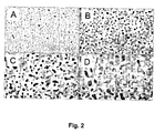
Fig. 2 shows Scanning Electron Micrographs of the deposited layer (copper substrate) after etching. A: 8% Zn etched for 30 minutes. B: 40% Zn etched for 30 minutes. C: 40% Zn etched for 4 hours. D: 40% Zn etched for 24 hours, -
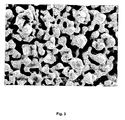
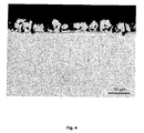
Fig. 3 and4 show the surface of the porous coating deposited on an aluminium rod (Fig. 4 is a cross section), after etching, -
Fig. 5 is a schematic drawing of a system for sample preparation (deposition of SnZn alloys with well defined agitation) as described in Example 3, and -
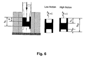
Fig. 6 illustrates the friction measurement as described in Example 4. - As mentioned above, the invention concerns a layer in the form of a thin, porous metallic film, which is electrochemically deposited on a workpiece surface. Further, the invention concerns a process for producing a microporous layer for lowering friction in metal forming processes on such a metal substrate, wherein the following steps are carried out:
- (1) selecting one or more alloys, each consisting of two or more phases capable of providing a thin metallic film consisting of a mixture of fine grains rather than a solid solution,
- (2) electrochemically depositing the alloy(s) on the metallic substrate and
- (3) selectively removing one of the metals or phases by chemical or electrochemical etching,
- The electrochemically deposited alloy is selected among FeIn, SnZn, AgCo, AgBi, AgFe, AgNi, InZn, BiCo, BiCu, BiSn, BiZn, PdCu, PdCo, CoCu, AgCu, AuCu and AuCo based-alloys. Preferably the electrochemically deposited alloy is a SnZn based-alloy.
- By selecting one or more alloys, each consisting of two or more phases capable of providing a thin metallic film it becomes possible to regulate the number of pores per area unit as well as the depth of the individual pores.
- The chemical or electrochemical etching is carried out by means of a solution dissolving a selected metallic phase, said solution being a concentrated or diluted inorganic acid, organic acid, inorganic base, organic base or mixtures thereof. Preferably, the etching is carried out with diluted hydrochloric acid, especially when the electrochemically deposited alloy is SnZn.
- The etching time may be accelerated by increasing the acid concentration, by using electrochemical etching, by increasing the temperature, by applying ultrasonic agitation (or other types of agitation) or by combinations of these accelerating measures.
- The surface of the porous coating after etching appears from the photographs in
Fig. 2 - 4 , where -
Fig. 2 shows the surface of a copper ring electroplated with SnZn and subsequently etched (various compositions and etching times) with diluted HCl, -
Fig. 3 shows the surface of an aluminium rod electroplated with SnZn and subsequently etched with diluted HCl, and -
Fig. 4 is a cross section of the aluminium rod, the surface of which is shown inFig. 3 . - The invention may be used not only for the treatment of workpieces in macro-scale, but also as a lubrication carrier for cold forming of micro-scale components, such as potentiometer axles for hearing aids. As regards the forming of micro-scale components, the conventional solid film lubrication with phosphate coating and soap lubrication often is inappropriate due to (a) packing of dies with excess lubricant and (b) inability to obtain close tolerances, as film thickness of lubricant is of the same order of magnitude as component detailed being formed. Liquid lubricants are preferred, but because galling problems can be expected, a combination of an ultra-thin, porous metallic film and a liquid lubricant is used to overcome these problems.
- The invention is illustrated in more details in the following examples.
- This example describes the electroplating and etching of a copper substrate.
- The copper substrate (a Cu-plate) was degreased cathodically in an alkaline solution and activated (pickled) in a commercial acidic solution. Then the SnZn alloy was electrodeposited on the copper plate at an applied current density of 1 A/dm2 at a bath temperature of 40 °C with magnetic stirring (up to 500 rpm) in a commercial electrolyte for 12 minutes.
- The commercial electrolyte had the following composition: 0.6 l/l SLOTOLOY ZSN 21; 0.013 l/l FS 20; 0.04 l/l SLOTOLOY ZSN 22; 0.0015 l/l SLOTOLOY ZSN 23; 70 g/l ZnCl2; 45 g/l KCl, and 30 g/l H3BO3.
- The thickness of the electrodeposit was 5 µm, and the Zn content in the deposit may vary from 10 to 40 at.% depending on the agitation.
- A selective etching of the zinc in the SnZn alloy deposit was carried out at room temperature with diluted HCl (1 part concentrated 37% hydro chloric acid and 9 parts destilled water) for 0.5; 1; 4 and 24 hours, respectively.
- The geometry of the porous coating of the etched SnZn alloy depends on the composition and the etching conditions. The number and size of holes in the etched SnZn alloy increases with the Zn content. A Zn content of about 10 at.% in the alloy deposit is too low for fabricating a porous coating.
- This example presents results obtained by using a friction test known as the ring compression test.
- In the ring compression test, friction is measured by the relationship between height reduction and decrease of inner diameter of a ring of specified geometry being upset between planar anvils. In the test carried out for this example, rings of electrolytically pure copper with well specified geometry, height:inner diameter:outer diameter ratio of 2:3:6, were used. Combinations of rings with and without said coating were tested in combination with a lubricant.
- The Zn content decreases with increasing agitation speed in the cell, as shown in the table 2 below. The composition varies depending on the position of the sample. Also the geometry of the sample may give rise to this problem.
Table 2: Zn content for various positions (up, down, right, left) of samples Up Right Down Left 600 rpm 1.7 4.9 14.6 16.0 500 rpm 2.3 1.8 13.5 1.2 400 rpm 22.1 21.6 46.0 31.4 300 rpm 38.5 25.2 53.5 39.2 - For the electroplating with SnZn a 1 l beaker was used as electrochemical cell as shown in
Fig. 1 . Providing the test specimens, i.e. the copper rings, with said coating has significant impact on the friction between anvils and plane surfaces of test specimens, as it appears from Table 3. In order to obtain identical coatings on both sides, the copper ring was located in the centre between two tin anodes. Agitation was conducted by means of a magnetic stirrer. - The friction of a sample coated with a porous coating (SnZn alloy with 40 at.% Zn deposited with magnetic stirring at 400 rpm and a current density of 1 A/dm2 and then subsequently etched in diluted HCl for 4 hours) and a lubricant was measured. As reference an untreated copper ring was used. The surface of the porous coating after etching is shown in
Fig. 2C . - Using a commercial lubrication paste (Molykote) on uncoated as well as coated rings, the ring test gave a friction factor of f = 0.25 in the former case and f ≈ 0.16 in the latter case, i.e. the porous layer caused a decrease in friction of 36 %.
- Three combinations of said coating and the lubricant paste were applied. Table 3 below shows the combinations and a qualification of friction between anvils and plane sides of test specimens, ranked with lower friction being preferable.
Table 3 Coating Lubricant Ranked results Friction none (reference) applied worst highest coated not applied better lower coated applied best lowest - As can be seen from the table above, application of lubricant in combination with said coating results in the lowest friction between test specimen and anvils.
- For an alternative friction test (described in the next example) a wire with a diameter of 1.88 mm was provided. To make a homogeneous composition of the deposited alloy a rotating set-up involving planetary gears was installed in the system for SnZn alloy electrodeposition as shown in
Fig. 5 . Ten wires, each with a diameter of 1.88 mm and a length of 13 cm, were attached to the rotating set-up. - The problem of heterogeneous composition could be improved with this system compared to conventional systems. The Zn contents of the deposits appeared to be much lower (from 1.6 ± 0.2 to 3.7 ± 0.8 at.%), regardless of the agitation speed. Then the amount of tin concentrate FS 20 was decreased, while the amount of ZnCl2 was increased. Now the electrolyte had the following composition: 0.6 l/l SLOTOLOY ZSN 21; 0.009 l/l FS 20; 0.04 l/l SLOTOLOY ZSN 22; 0.0015 l/l SLOTOLOY ZSN 23; 98 g/l ZnCl2; 45 g/l KCI, and 30 g/l H3BO3. The current density was 1 A/dm2 and the temperature 40 °C.
- The compositions of the deposits for the modified electrolyte were analyzed, both at the top and at the bottom of the samples. The composition distribution was homogeneous.
Table 4: Zn content (at.%) in deposits from the modified electrolyte 1 (top) 2 (top) 3 (bottom) 4 (bottom) 800 rpm 30.9 30.2 27.2 31.1 500 rpm 35.0 34.8 34.0 36.7 400 rpm 36.0 35.3 300 rpm 49.5 43.3 44.2 44.9 - The geometry of the porous coating of the etched SnZn alloy is clearly different (see
Fig. 3 ) from one deposited from the previous system: It is more like a three-dimensional network (and may affect the friction). - This example presents results obtained by using a friction test known as the double cup extrusion test, see
Fig. 6 . - In the double cup extrusion test, the cylindrical slug is inserted in a container with the same nominal diameter. The upper punch is moving downwards while the container and the lower punch are kept stationary, see
Fig. 6 . In case of zero friction along the container wall the upper and lower cup will develop identically, i.e. hu/hl = 1, whereas increasing friction will cause an increasing ratio between the upper and the lower cup height. The test is carried out in a Ø27mm container with a reduction r = (DP/D0)2 = 0.69. The shape of punch nose was chosen according to the recommendations of ICFG. The height/diameter ratio of the billets is chosen as h0/d0=1. The test principle is illustrated inFig. 6 . - The experiments were performed in pure silver with a stress-strain curve: σ = 295 ε0.27 [N/mm2] determined by uni-axial compression testing. Three different surface treatments were tested: The new porous coating lubricated with MoDX paste (commercial product called Molykote) or mineral oil or MoDX paste added directly on a clean surface. The relative punch travel z/h0 is aimed at 20, 40 and 60%. In the table below, the friction values determined are shown.
- From the results obtained it is clear, that the coating has no influence when lubricated with MoDX but seems to perform very well when lubricated with mineral oil, where rather low friction is obtained especially for large punch travel z/h0=0.6.
- Friction coefficients and friction factors found by double cup extrusion test:
No coat. + MoDX Coat. + MoDX Coat. + oil Friction coefficient (µ) > 0.2 > 0.2 < 0.05 Friction factor (m) > 0.6 > 0.6 0.05-0.4 - In conclusion, it has been shown that the porous surface geometry of an etched SnZn alloy deposit is determined by the composition of the alloy. About 40 at.% Zn appears to be reasonable. Further, it is possible to control the composition by changing the agitation in the cell (but it is difficult to obtain identical and reproducible compositions). The friction is improved with a porous coating of etched SnZn alloy with 40 at.% Zn.
Claims (10)
- A process for producing a microporous layer for lowering friction in metal forming processes on a metal substrate, said layer being- a thin metallic film, which has been electrochemically deposited on the surface of a metal substrate, and- capable of capturing a lubricant film in its pores,wherein the following steps are carried out:(1) selecting one or more alloys, each consisting of two or more phases capable of providing a thin metallic film consisting of a mixture of fine grains rather than a solid solution,(2) electrochemically depositing the alloy(s) on the metallic substrate, and(3) selectively removing one of the metals or phases by chemical or electrochemical etching,leaving a microporous layer on the substrate surface and thereby providing an ideal surface for said metal forming.
- The process according to claim 1, wherein the electrochemically deposited alloy is selected among FeIn, SnZn, AgCo, AgBi, AgFe, AgNi, InZn, BiCo, BiCu, BiSn, BiZn, PdCu, PdCo, CoCu, AgCu, AuCu and AuCo.
- The process according to claim 2, wherein the electrochemically deposited alloy is SnZn.
- The process according to any of the claims 1 - 3, wherein the chemical or electrochemical etching is carried out by means of a solution dissolving a selected metallic phase, said solution being a concentrated or diluted inorganic acid, organic acid, inorganic base, organic base or mixtures thereof.
- The process according to any of the claims 1 - 4, wherein the chemical etching of the Zn phase is carried out with diluted hydrochloric acid.
- The use of a microporous layer as a lubrication carrier for cold forming of metals, wherein the microporous layer originates from a ZnSn alloy having a Zn-content of between 10 and 40%.
- The use of a microporous layer according to claim 6 as a lubrication carrier for cold forming of metallic micro-scale components.
- The use according to claims 6 or 7 for the electroplating of a copper substrate, wherein the electrochemically deposited alloy is SnZn and the chemical etching of the Zn phase is carried out with diluted hydrochloric acid.
- Use of a microporous layer for lowering friction in metal forming processes, wherein the microporous layer originates from a ZnSn alloy having a Zn-content of between 10 and 40%.
- Use according claim 9, wherein the microporous layer, is lubricated with a liquid, such as a mineral oil or an organic oil, with a viscosity low enough to penetrate into the pores of the porous coating.
Priority Applications (1)
| Application Number | Priority Date | Filing Date | Title |
|---|---|---|---|
| EP08758242.5A EP2176447B1 (en) | 2007-06-21 | 2008-06-20 | A microporous layer for lowering friction in metal-forming processes |
Applications Claiming Priority (4)
| Application Number | Priority Date | Filing Date | Title |
|---|---|---|---|
| US92929907P | 2007-06-21 | 2007-06-21 | |
| EP07388045A EP2006420A1 (en) | 2007-06-22 | 2007-06-22 | A microporous layer for lowering friction in metal forming processes |
| PCT/DK2008/000233 WO2008154925A1 (en) | 2007-06-21 | 2008-06-20 | A microporous layer for lowering friction in metal-forming processes |
| EP08758242.5A EP2176447B1 (en) | 2007-06-21 | 2008-06-20 | A microporous layer for lowering friction in metal-forming processes |
Publications (2)
| Publication Number | Publication Date |
|---|---|
| EP2176447A1 EP2176447A1 (en) | 2010-04-21 |
| EP2176447B1 true EP2176447B1 (en) | 2013-12-25 |
Family
ID=38754477
Family Applications (2)
| Application Number | Title | Priority Date | Filing Date |
|---|---|---|---|
| EP07388045A Withdrawn EP2006420A1 (en) | 2007-06-21 | 2007-06-22 | A microporous layer for lowering friction in metal forming processes |
| EP08758242.5A Not-in-force EP2176447B1 (en) | 2007-06-21 | 2008-06-20 | A microporous layer for lowering friction in metal-forming processes |
Family Applications Before (1)
| Application Number | Title | Priority Date | Filing Date |
|---|---|---|---|
| EP07388045A Withdrawn EP2006420A1 (en) | 2007-06-21 | 2007-06-22 | A microporous layer for lowering friction in metal forming processes |
Country Status (5)
| Country | Link |
|---|---|
| US (1) | US20100137171A1 (en) |
| EP (2) | EP2006420A1 (en) |
| JP (1) | JP5602013B2 (en) |
| DK (1) | DK2176447T3 (en) |
| WO (1) | WO2008154925A1 (en) |
Cited By (1)
| Publication number | Priority date | Publication date | Assignee | Title |
|---|---|---|---|---|
| DE102014005941A1 (en) * | 2014-04-24 | 2015-11-12 | Te Connectivity Germany Gmbh | Method for producing an electrical contact element for avoiding tin whisker formation, and contact element |
Families Citing this family (2)
| Publication number | Priority date | Publication date | Assignee | Title |
|---|---|---|---|---|
| CN109988932B (en) * | 2017-12-29 | 2021-01-26 | 清华大学 | Preparation method of nanoporous copper |
| JP7053411B2 (en) * | 2018-08-31 | 2022-04-12 | 株式会社アイシン | Manufacturing method of metal parts |
Family Cites Families (17)
| Publication number | Priority date | Publication date | Assignee | Title |
|---|---|---|---|---|
| US2450339A (en) * | 1943-09-17 | 1948-09-28 | Mallory & Co Inc P R | Method of making porous metal filters |
| US2447980A (en) * | 1945-01-29 | 1948-08-24 | Mallory & Co Inc P R | Method of making porous bearing surfaces |
| DE1546005B1 (en) * | 1964-02-27 | 1971-01-21 | Schmidt Gmbh Karl | Treatment of sliding surfaces with chemically or galvanically coated surfaces |
| US3787294A (en) * | 1971-12-07 | 1974-01-22 | S Kurosaki | Process for producing a solid lubricant self-supplying-type co-deposited metal film |
| JPS558588B2 (en) * | 1972-02-10 | 1980-03-05 | ||
| US4065365A (en) * | 1975-03-18 | 1977-12-27 | Aplicaciones Industriales De Cromo Duro, S.A. | Method for improving frictional surface in cylinders or sleeves of internal combustion engines |
| GB1558683A (en) * | 1977-10-26 | 1980-01-09 | Tools For Bending Inc | Surface or a chromium-containing composition |
| JPS575893A (en) * | 1980-06-16 | 1982-01-12 | Fujikura Ltd | Surface treating method for porous metallic article |
| JPS57109242A (en) * | 1980-12-26 | 1982-07-07 | Seiko Epson Corp | Porous thin film |
| JPS5913073A (en) * | 1982-07-14 | 1984-01-23 | Usui Internatl Ind Co Ltd | Metallic structural body coated with ceramic |
| CN1007737B (en) * | 1988-04-16 | 1990-04-25 | 华东师范大学 | Porous nickel active cathode and preparation method thereof |
| JPH102429A (en) * | 1996-06-14 | 1998-01-06 | Hitachi Metals Ltd | Gas cock |
| WO2003010357A1 (en) * | 2001-07-24 | 2003-02-06 | Creatic Japan, Inc. | Electroconductive structure and electroplating method using the structure |
| US6805972B2 (en) * | 2002-08-27 | 2004-10-19 | Johns Hopkins University | Method of forming nanoporous membranes |
| WO2004043292A2 (en) * | 2002-11-13 | 2004-05-27 | Setagon, Inc. | Medical devices having porous layers and methods for making same |
| DE10326788B4 (en) * | 2003-06-13 | 2005-05-25 | Robert Bosch Gmbh | Contact surfaces for electrical contacts and methods of manufacture |
| EP2092092A1 (en) * | 2006-11-15 | 2009-08-26 | Massachusetts Institute Of Technology | Methods for tailoring the surface topography of a nanocrystalline or amorphous metal or alloy and articles formed by such methods |
-
2007
- 2007-06-22 EP EP07388045A patent/EP2006420A1/en not_active Withdrawn
-
2008
- 2008-06-20 WO PCT/DK2008/000233 patent/WO2008154925A1/en not_active Ceased
- 2008-06-20 DK DK08758242.5T patent/DK2176447T3/en active
- 2008-06-20 JP JP2010512520A patent/JP5602013B2/en not_active Expired - Fee Related
- 2008-06-20 US US12/452,118 patent/US20100137171A1/en not_active Abandoned
- 2008-06-20 EP EP08758242.5A patent/EP2176447B1/en not_active Not-in-force
Cited By (1)
| Publication number | Priority date | Publication date | Assignee | Title |
|---|---|---|---|---|
| DE102014005941A1 (en) * | 2014-04-24 | 2015-11-12 | Te Connectivity Germany Gmbh | Method for producing an electrical contact element for avoiding tin whisker formation, and contact element |
Also Published As
| Publication number | Publication date |
|---|---|
| US20100137171A1 (en) | 2010-06-03 |
| EP2176447A1 (en) | 2010-04-21 |
| EP2006420A1 (en) | 2008-12-24 |
| JP5602013B2 (en) | 2014-10-08 |
| DK2176447T3 (en) | 2014-03-24 |
| JP2010530475A (en) | 2010-09-09 |
| WO2008154925A1 (en) | 2008-12-24 |
Similar Documents
| Publication | Publication Date | Title |
|---|---|---|
| TWI438784B (en) | Conductive member and manufacturing method thereof | |
| US6656606B1 (en) | Electroplated aluminum parts and process of production | |
| US20090321268A1 (en) | Electrodeposited film having sliding function and coated article therewith | |
| US3787294A (en) | Process for producing a solid lubricant self-supplying-type co-deposited metal film | |
| KR20000010849A (en) | Battery case and surface treated steel sheet for battery case | |
| Zhang | Tin and tin alloys for lead-free solder | |
| EP3150743B1 (en) | Bismuth electroplating baths and methods of electroplating bismuth on a substrate | |
| CN109790867B (en) | Multilayer plain bearing elements | |
| DK2176447T3 (en) | Microporous layer to decrease the friction in metal forming processes | |
| US3982314A (en) | Method of producing tin coated steel sheet used for seamless steel container | |
| US5849423A (en) | Zinciferous plated steel sheet and method for manufacturing same | |
| KR0144646B1 (en) | Composition and process for surface treating metal prior to cold working | |
| JP6682691B1 (en) | Surface-treated galvanized steel sheet and method for producing the same | |
| DE102009019601B3 (en) | Layer composite material for sliding elements and for plain bearings, particularly crankshaft bearing, camshaft bearings or connecting rod bearings, comprises primary layer made from copper alloy or aluminum alloy | |
| EP3816326B1 (en) | Acidic aqueous binary silver-bismuth alloy electroplating compositions and methods | |
| KR20170120547A (en) | Sn-PLATED MATERIAL FOR ELECTRONIC COMPONENT | |
| US4061430A (en) | Socket structure for the ball of a ball point pen refill | |
| US4139424A (en) | Socket structure for the ball of a ball point pen refill | |
| US4566953A (en) | Pulse plating of nickel-antimony films | |
| Lowenheim | Guide to the Selection and use of Electroplated and Related Finishes | |
| Gamburg et al. | Technologies for the electrodeposition of metals and alloys: electrolytes and processes | |
| KR102912251B1 (en) | Silver coating for high temperature applications | |
| Dennis et al. | Properties of cobalt-molybdenum and cobalt-tungsten electrodeposits | |
| JPH08120431A (en) | Alloyed hot-dip galvanized steel sheet excellent in press formability and method for producing the same | |
| Narayanan et al. | Electro-and electroless plated coatings for corrosion protection |
Legal Events
| Date | Code | Title | Description |
|---|---|---|---|
| PUAI | Public reference made under article 153(3) epc to a published international application that has entered the european phase |
Free format text: ORIGINAL CODE: 0009012 |
|
| 17P | Request for examination filed |
Effective date: 20100121 |
|
| AK | Designated contracting states |
Kind code of ref document: A1 Designated state(s): AT BE BG CH CY CZ DE DK EE ES FI FR GB GR HR HU IE IS IT LI LT LU LV MC MT NL NO PL PT RO SE SI SK TR |
|
| AX | Request for extension of the european patent |
Extension state: AL BA MK RS |
|
| DAX | Request for extension of the european patent (deleted) | ||
| 17Q | First examination report despatched |
Effective date: 20120330 |
|
| REG | Reference to a national code |
Ref country code: DE Ref legal event code: R079 Ref document number: 602008029525 Country of ref document: DE Free format text: PREVIOUS MAIN CLASS: C25D0003600000 Ipc: C25D0005480000 |
|
| GRAP | Despatch of communication of intention to grant a patent |
Free format text: ORIGINAL CODE: EPIDOSNIGR1 |
|
| RIC1 | Information provided on ipc code assigned before grant |
Ipc: C25D 3/60 20060101ALN20130619BHEP Ipc: C25D 5/48 20060101AFI20130619BHEP Ipc: C25D 7/10 20060101ALI20130619BHEP Ipc: C23F 1/30 20060101ALI20130619BHEP Ipc: C23F 1/44 20060101ALI20130619BHEP |
|
| INTG | Intention to grant announced |
Effective date: 20130711 |
|
| GRAS | Grant fee paid |
Free format text: ORIGINAL CODE: EPIDOSNIGR3 |
|
| GRAA | (expected) grant |
Free format text: ORIGINAL CODE: 0009210 |
|
| AK | Designated contracting states |
Kind code of ref document: B1 Designated state(s): AT BE BG CH CY CZ DE DK EE ES FI FR GB GR HR HU IE IS IT LI LT LU LV MC MT NL NO PL PT RO SE SI SK TR |
|
| REG | Reference to a national code |
Ref country code: GB Ref legal event code: FG4D |
|
| REG | Reference to a national code |
Ref country code: CH Ref legal event code: EP |
|
| REG | Reference to a national code |
Ref country code: AT Ref legal event code: REF Ref document number: 646711 Country of ref document: AT Kind code of ref document: T Effective date: 20140115 |
|
| REG | Reference to a national code |
Ref country code: IE Ref legal event code: FG4D |
|
| REG | Reference to a national code |
Ref country code: DE Ref legal event code: R096 Ref document number: 602008029525 Country of ref document: DE Effective date: 20140213 |
|
| REG | Reference to a national code |
Ref country code: DK Ref legal event code: T3 Effective date: 20140320 |
|
| REG | Reference to a national code |
Ref country code: CH Ref legal event code: NV Representative=s name: BOVARD AG, CH |
|
| PG25 | Lapsed in a contracting state [announced via postgrant information from national office to epo] |
Ref country code: SE Free format text: LAPSE BECAUSE OF FAILURE TO SUBMIT A TRANSLATION OF THE DESCRIPTION OR TO PAY THE FEE WITHIN THE PRESCRIBED TIME-LIMIT Effective date: 20131225 Ref country code: HR Free format text: LAPSE BECAUSE OF FAILURE TO SUBMIT A TRANSLATION OF THE DESCRIPTION OR TO PAY THE FEE WITHIN THE PRESCRIBED TIME-LIMIT Effective date: 20131225 Ref country code: NO Free format text: LAPSE BECAUSE OF FAILURE TO SUBMIT A TRANSLATION OF THE DESCRIPTION OR TO PAY THE FEE WITHIN THE PRESCRIBED TIME-LIMIT Effective date: 20140325 Ref country code: LT Free format text: LAPSE BECAUSE OF FAILURE TO SUBMIT A TRANSLATION OF THE DESCRIPTION OR TO PAY THE FEE WITHIN THE PRESCRIBED TIME-LIMIT Effective date: 20131225 Ref country code: FI Free format text: LAPSE BECAUSE OF FAILURE TO SUBMIT A TRANSLATION OF THE DESCRIPTION OR TO PAY THE FEE WITHIN THE PRESCRIBED TIME-LIMIT Effective date: 20131225 |
|
| REG | Reference to a national code |
Ref country code: NL Ref legal event code: VDEP Effective date: 20131225 |
|
| REG | Reference to a national code |
Ref country code: AT Ref legal event code: MK05 Ref document number: 646711 Country of ref document: AT Kind code of ref document: T Effective date: 20131225 |
|
| REG | Reference to a national code |
Ref country code: LT Ref legal event code: MG4D |
|
| PG25 | Lapsed in a contracting state [announced via postgrant information from national office to epo] |
Ref country code: LV Free format text: LAPSE BECAUSE OF FAILURE TO SUBMIT A TRANSLATION OF THE DESCRIPTION OR TO PAY THE FEE WITHIN THE PRESCRIBED TIME-LIMIT Effective date: 20131225 |
|
| PG25 | Lapsed in a contracting state [announced via postgrant information from national office to epo] |
Ref country code: EE Free format text: LAPSE BECAUSE OF FAILURE TO SUBMIT A TRANSLATION OF THE DESCRIPTION OR TO PAY THE FEE WITHIN THE PRESCRIBED TIME-LIMIT Effective date: 20131225 Ref country code: BE Free format text: LAPSE BECAUSE OF FAILURE TO SUBMIT A TRANSLATION OF THE DESCRIPTION OR TO PAY THE FEE WITHIN THE PRESCRIBED TIME-LIMIT Effective date: 20131225 Ref country code: IS Free format text: LAPSE BECAUSE OF FAILURE TO SUBMIT A TRANSLATION OF THE DESCRIPTION OR TO PAY THE FEE WITHIN THE PRESCRIBED TIME-LIMIT Effective date: 20140425 |
|
| PGFP | Annual fee paid to national office [announced via postgrant information from national office to epo] |
Ref country code: GB Payment date: 20140627 Year of fee payment: 7 |
|
| PG25 | Lapsed in a contracting state [announced via postgrant information from national office to epo] |
Ref country code: RO Free format text: LAPSE BECAUSE OF FAILURE TO SUBMIT A TRANSLATION OF THE DESCRIPTION OR TO PAY THE FEE WITHIN THE PRESCRIBED TIME-LIMIT Effective date: 20131225 Ref country code: AT Free format text: LAPSE BECAUSE OF FAILURE TO SUBMIT A TRANSLATION OF THE DESCRIPTION OR TO PAY THE FEE WITHIN THE PRESCRIBED TIME-LIMIT Effective date: 20131225 Ref country code: ES Free format text: LAPSE BECAUSE OF FAILURE TO SUBMIT A TRANSLATION OF THE DESCRIPTION OR TO PAY THE FEE WITHIN THE PRESCRIBED TIME-LIMIT Effective date: 20131225 Ref country code: PT Free format text: LAPSE BECAUSE OF FAILURE TO SUBMIT A TRANSLATION OF THE DESCRIPTION OR TO PAY THE FEE WITHIN THE PRESCRIBED TIME-LIMIT Effective date: 20140428 Ref country code: PL Free format text: LAPSE BECAUSE OF FAILURE TO SUBMIT A TRANSLATION OF THE DESCRIPTION OR TO PAY THE FEE WITHIN THE PRESCRIBED TIME-LIMIT Effective date: 20131225 Ref country code: NL Free format text: LAPSE BECAUSE OF FAILURE TO SUBMIT A TRANSLATION OF THE DESCRIPTION OR TO PAY THE FEE WITHIN THE PRESCRIBED TIME-LIMIT Effective date: 20131225 Ref country code: CZ Free format text: LAPSE BECAUSE OF FAILURE TO SUBMIT A TRANSLATION OF THE DESCRIPTION OR TO PAY THE FEE WITHIN THE PRESCRIBED TIME-LIMIT Effective date: 20131225 Ref country code: SK Free format text: LAPSE BECAUSE OF FAILURE TO SUBMIT A TRANSLATION OF THE DESCRIPTION OR TO PAY THE FEE WITHIN THE PRESCRIBED TIME-LIMIT Effective date: 20131225 Ref country code: CY Free format text: LAPSE BECAUSE OF FAILURE TO SUBMIT A TRANSLATION OF THE DESCRIPTION OR TO PAY THE FEE WITHIN THE PRESCRIBED TIME-LIMIT Effective date: 20131225 |
|
| PGFP | Annual fee paid to national office [announced via postgrant information from national office to epo] |
Ref country code: DE Payment date: 20140624 Year of fee payment: 7 Ref country code: IT Payment date: 20140623 Year of fee payment: 7 Ref country code: CH Payment date: 20140617 Year of fee payment: 7 |
|
| REG | Reference to a national code |
Ref country code: DE Ref legal event code: R097 Ref document number: 602008029525 Country of ref document: DE |
|
| PGFP | Annual fee paid to national office [announced via postgrant information from national office to epo] |
Ref country code: DK Payment date: 20140625 Year of fee payment: 7 |
|
| PLBE | No opposition filed within time limit |
Free format text: ORIGINAL CODE: 0009261 |
|
| STAA | Information on the status of an ep patent application or granted ep patent |
Free format text: STATUS: NO OPPOSITION FILED WITHIN TIME LIMIT |
|
| PGFP | Annual fee paid to national office [announced via postgrant information from national office to epo] |
Ref country code: FR Payment date: 20140630 Year of fee payment: 7 |
|
| 26N | No opposition filed |
Effective date: 20140926 |
|
| REG | Reference to a national code |
Ref country code: DE Ref legal event code: R097 Ref document number: 602008029525 Country of ref document: DE Effective date: 20140926 |
|
| PG25 | Lapsed in a contracting state [announced via postgrant information from national office to epo] |
Ref country code: MC Free format text: LAPSE BECAUSE OF FAILURE TO SUBMIT A TRANSLATION OF THE DESCRIPTION OR TO PAY THE FEE WITHIN THE PRESCRIBED TIME-LIMIT Effective date: 20131225 Ref country code: LU Free format text: LAPSE BECAUSE OF FAILURE TO SUBMIT A TRANSLATION OF THE DESCRIPTION OR TO PAY THE FEE WITHIN THE PRESCRIBED TIME-LIMIT Effective date: 20140620 |
|
| REG | Reference to a national code |
Ref country code: IE Ref legal event code: MM4A |
|
| PG25 | Lapsed in a contracting state [announced via postgrant information from national office to epo] |
Ref country code: IE Free format text: LAPSE BECAUSE OF NON-PAYMENT OF DUE FEES Effective date: 20140620 |
|
| PG25 | Lapsed in a contracting state [announced via postgrant information from national office to epo] |
Ref country code: SI Free format text: LAPSE BECAUSE OF FAILURE TO SUBMIT A TRANSLATION OF THE DESCRIPTION OR TO PAY THE FEE WITHIN THE PRESCRIBED TIME-LIMIT Effective date: 20131225 |
|
| REG | Reference to a national code |
Ref country code: DE Ref legal event code: R119 Ref document number: 602008029525 Country of ref document: DE |
|
| REG | Reference to a national code |
Ref country code: DK Ref legal event code: EBP Effective date: 20150630 |
|
| PG25 | Lapsed in a contracting state [announced via postgrant information from national office to epo] |
Ref country code: IT Free format text: LAPSE BECAUSE OF NON-PAYMENT OF DUE FEES Effective date: 20150620 |
|
| REG | Reference to a national code |
Ref country code: CH Ref legal event code: PL |
|
| GBPC | Gb: european patent ceased through non-payment of renewal fee |
Effective date: 20150620 |
|
| PG25 | Lapsed in a contracting state [announced via postgrant information from national office to epo] |
Ref country code: MT Free format text: LAPSE BECAUSE OF FAILURE TO SUBMIT A TRANSLATION OF THE DESCRIPTION OR TO PAY THE FEE WITHIN THE PRESCRIBED TIME-LIMIT Effective date: 20131225 |
|
| REG | Reference to a national code |
Ref country code: FR Ref legal event code: ST Effective date: 20160229 |
|
| PG25 | Lapsed in a contracting state [announced via postgrant information from national office to epo] |
Ref country code: LI Free format text: LAPSE BECAUSE OF NON-PAYMENT OF DUE FEES Effective date: 20150630 Ref country code: DE Free format text: LAPSE BECAUSE OF NON-PAYMENT OF DUE FEES Effective date: 20160101 Ref country code: GB Free format text: LAPSE BECAUSE OF NON-PAYMENT OF DUE FEES Effective date: 20150620 Ref country code: CH Free format text: LAPSE BECAUSE OF NON-PAYMENT OF DUE FEES Effective date: 20150630 |
|
| PG25 | Lapsed in a contracting state [announced via postgrant information from national office to epo] |
Ref country code: BG Free format text: LAPSE BECAUSE OF FAILURE TO SUBMIT A TRANSLATION OF THE DESCRIPTION OR TO PAY THE FEE WITHIN THE PRESCRIBED TIME-LIMIT Effective date: 20131225 Ref country code: FR Free format text: LAPSE BECAUSE OF NON-PAYMENT OF DUE FEES Effective date: 20150630 |
|
| PG25 | Lapsed in a contracting state [announced via postgrant information from national office to epo] |
Ref country code: GR Free format text: LAPSE BECAUSE OF FAILURE TO SUBMIT A TRANSLATION OF THE DESCRIPTION OR TO PAY THE FEE WITHIN THE PRESCRIBED TIME-LIMIT Effective date: 20140326 |
|
| PG25 | Lapsed in a contracting state [announced via postgrant information from national office to epo] |
Ref country code: TR Free format text: LAPSE BECAUSE OF FAILURE TO SUBMIT A TRANSLATION OF THE DESCRIPTION OR TO PAY THE FEE WITHIN THE PRESCRIBED TIME-LIMIT Effective date: 20131225 Ref country code: HU Free format text: LAPSE BECAUSE OF FAILURE TO SUBMIT A TRANSLATION OF THE DESCRIPTION OR TO PAY THE FEE WITHIN THE PRESCRIBED TIME-LIMIT; INVALID AB INITIO Effective date: 20080620 |
|
| PG25 | Lapsed in a contracting state [announced via postgrant information from national office to epo] |
Ref country code: DK Free format text: LAPSE BECAUSE OF NON-PAYMENT OF DUE FEES Effective date: 20150630 |