EP2176144B1 - Module à grande charnière ouverte pour nettoyage facile - Google Patents
Module à grande charnière ouverte pour nettoyage facile Download PDFInfo
- Publication number
- EP2176144B1 EP2176144B1 EP08772891A EP08772891A EP2176144B1 EP 2176144 B1 EP2176144 B1 EP 2176144B1 EP 08772891 A EP08772891 A EP 08772891A EP 08772891 A EP08772891 A EP 08772891A EP 2176144 B1 EP2176144 B1 EP 2176144B1
- Authority
- EP
- European Patent Office
- Prior art keywords
- belt
- link ends
- module
- link
- modules
- Prior art date
- Legal status (The legal status is an assumption and is not a legal conclusion. Google has not performed a legal analysis and makes no representation as to the accuracy of the status listed.)
- Not-in-force
Links
Images


Classifications
-
- B—PERFORMING OPERATIONS; TRANSPORTING
- B65—CONVEYING; PACKING; STORING; HANDLING THIN OR FILAMENTARY MATERIAL
- B65G—TRANSPORT OR STORAGE DEVICES, e.g. CONVEYORS FOR LOADING OR TIPPING, SHOP CONVEYOR SYSTEMS OR PNEUMATIC TUBE CONVEYORS
- B65G17/00—Conveyors having an endless traction element, e.g. a chain, transmitting movement to a continuous or substantially-continuous load-carrying surface or to a series of individual load-carriers; Endless-chain conveyors in which the chains form the load-carrying surface
- B65G17/06—Conveyors having an endless traction element, e.g. a chain, transmitting movement to a continuous or substantially-continuous load-carrying surface or to a series of individual load-carriers; Endless-chain conveyors in which the chains form the load-carrying surface having a load-carrying surface formed by a series of interconnected, e.g. longitudinal, links, plates, or platforms
- B65G17/08—Conveyors having an endless traction element, e.g. a chain, transmitting movement to a continuous or substantially-continuous load-carrying surface or to a series of individual load-carriers; Endless-chain conveyors in which the chains form the load-carrying surface having a load-carrying surface formed by a series of interconnected, e.g. longitudinal, links, plates, or platforms the surface being formed by the traction element
-
- B—PERFORMING OPERATIONS; TRANSPORTING
- B65—CONVEYING; PACKING; STORING; HANDLING THIN OR FILAMENTARY MATERIAL
- B65G—TRANSPORT OR STORAGE DEVICES, e.g. CONVEYORS FOR LOADING OR TIPPING, SHOP CONVEYOR SYSTEMS OR PNEUMATIC TUBE CONVEYORS
- B65G2207/00—Indexing codes relating to constructional details, configuration and additional features of a handling device, e.g. Conveyors
- B65G2207/26—Hygienic features, e.g. easy to sanitize
Definitions
- This invention relates to conveyor belts and, more particularly, to modular plastic conveyor belts formed of rows of plastic belt modules pivotally interlinked by transverse pivot rods.
- Modular belts and particular flat top modular belts are widely used for the transport of foodstuff with direct contact of the foodstuff with the conveying surface of the belt. Belts and equipment for such transport must be regularly cleaned in order to avoid contamination of the food with decomposed residual matters and bacteria.
- the modules are usually constructed from plastics that are approved for direct contact with foodstuff.
- the modules typically have a closed, smooth surface that cleans well.
- the main area of difficulty is the hinge where the modules are connected together.
- the hinges typically have gaps where foodstuff can penetrate and become trapped. These residual deposits of foodstuff are difficult to remove.
- U.S. Patent No. 6,725,883 which is assigned to the assignee of the present invention.
- Another design is shown in U.S. Patent No. 5,706,934 .
- These belt designs are further characterized by a smooth flat bottom side that is only interrupted by the links needed to connect the modules to form a belt.
- this type of belt is used in a bricklayed assembly of more than one module per module row.
- These bricklayed belts have small gaps where the module ends meet.
- long modules were used to form a chain-like belt and to eliminate the bricklayed arrangement completely as shown in U.S. Patent No. 6,758,329 .
- the gaps between the module ends are eliminated, these long modules still suffer from a large number of gaps between the equally spaced interdigited links and therefore there was still room for improvement.
- a further improvement is possible by eliminating some of the links and therefore reducing the number of gaps between the side of the interdigited links. This design offers even better cleanability due to less hinge links but results in low belt strength.
- the present invention meets the above described need by providing a belt module according to the independent claim 1.
- Independent claim 10 defines a modular conveying belt according to the invention. Preferred embodiments will emerge from the dependent claims.
- the essence of the invention consists in a belt module that reduces the undesirable elasticity of the belt under load by having link pairs that are moved as close together as possible leaving large open spaces between the link pairs.
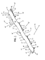
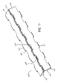
- a belt module 20 of the present invention has an upper conveying surface 23 that is generally smooth and flat.
- the upper conveying surface 23 extends from a first side edge 26 to a second side edge 29 in a direction transverse to the direction of belt travel indicated by arrow 32.
- the upper conveying surface 23 also includes a first edge 38 and a second edge 41 disposed opposite from the first edge 38.
- the shapes of the first and second edges 38 and 41 are defined by a plurality of link ends and openings.
- the first edge 38 has a first portion 39 extending in a direction transverse to the direction of belt travel.
- the first portion 39 extends to a first link end 44.
- the link end 44 forms a portion of the upper conveying surface 23 and also has a rounded end portion 47.
- the first link end 44 has a pair of side walls 50 and 53 defining a transverse thickness. On the side of the link end 44 adjacent to side wall 53 there is an elongate opening 56 in the conveying surface 23. The opposite end of the opening 56 is bordered by another link end 44 having a pair of side walls 50 and 53 defining a transverse thickness.
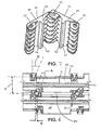
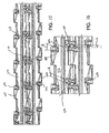
- the link ends 44 have transverse pivot rod openings 57 (best shown in Figs. 10-11 ) for receiving a pivot rod 59 to pivotally connect adjacent modules to form a belt 100 as shown in Fig. 2 .
- a corresponding opening 45 is provided on the side of the module 20 opposite from link end 44 . When adjacent modules 20 are intercalated as shown in Fig. 2 , link ends 44 fit into openings 45.
- the belt module 20 also includes a link end 65 having a plate 68 extending therefrom.
- the link end 65 and plate 68 have a width that is slightly smaller than the elongate opening 56 such that adjacent modules 20 are capable of being intercalated and connected by a pivot rod 59 to form a belt 100 capable of articulating around a sprocket (not shown).
- the belt module 20 also includes a link end 70 that is connected to a wider plate 72. The link end 70 and the wider plate 72 fit into an opening 75 in an adjacent module 20 as shown in Figs. 2 and 3 .
- the belt 100 may be formed by intercalating adjacent modules 20, aligning their transverse pivot rod openings 57 ( Fig. 3 ), and inserting a pivot rod 59 ( Fig. 3 ), as known to those of ordinary skill in the art based on this disclosure.
- the belt 100 forms a closed top surface with very minimal gaps to prevent foodstuff from becoming trapped between the belt modules 20.
- the link ends 44, 65, and 70 on one side of the belt module 20 intercalate with the corresponding openings 45, 69, and 75, on the opposite side of an adjacent belt module 20.
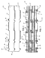
- Fig. 3 the bottom of belt 100 is shown.
- a longitudinal rib 101 is formed on the bottom surface 103.
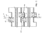
- the target is to reduce the transversal distance B to a minimum.
- This configuration of the link ends concentrates the shearing forces on the pivot rod 59 into two planes with a very small distance B between them and thus avoids rod bending and reduces belt elasticity.
- the link gap A of the two adjacent links must remain large enough to allow for easy cleaning.
- the link gap A is created by an angled shaping of the link ends.
- the gap A between the links is formed by the opposed side walls 106, 109 on adjacent link ends being substantially parallel to each other and disposed at an angle ⁇ with respect to the other side wall 112, 115 on each link end.
- ⁇ is approximately 20 degrees.
- the side wall 112, 115 opposite to the angled side wall 106, 109 may be parallel to the direction of belt travel or alternatively may be angled as well as discussed herein. The configuration of the opposite side wall allows for optimization of the link shape to keep sufficient link thickness S at the rearward link end.
- the underside of the module 20 may be flat or it may be provided with a plate-like surface (best shown in Figs. 10A and 11 ) that slopes away in the direction of belt travel ending at the belt edge between the link ends.
- the plate-like portion 110 of the module 20 may define a smooth and slightly concave back surface continuing across the module in the direction of belt travel.
- a gap 120 is formed between the edges of adjacent modules 20.
- the gap 120 provides access to the hinge area for cleaning when the belt 100 travels over the sprocket.
- the module pitch P is the distance between the same point on adjacent modules 20 in the direction of belt travel.
- the link pitch C is the largest distance between the same point on two adjacent link ends. In order to reduce the number of link ends and therefore reduce the number of gaps, the link pitch C may be greater than or equal to the module pitch P.
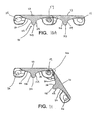
- the gap 120 is at its maximum width when the belt 100 is positioned as shown in Fig. 6 .
- the belt 100 is rotated around the pivot rod 59 when the belt 100 is turning around a sprocket or drum.
- the hinge gap A is enlarged due to the bending of the belt 100 around the sprocket.
- the longitudinal rib 101 extends from the bottom surface 103 of the module and provides a point of engagement for the teeth of the sprocket (not shown).
- the longitudinal rib 101 has a top wall 123 and a pair of side walls 126, 129 extending from opposite sides of the top wall 123.
- the side walls 126 and 129 extend toward the bottom wall 103 of the module 20.
- the side walls 126 and 129 intersect with the plate-like portion 110 in a smooth curve that extends from the rib 101 toward the link ends.
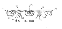
- the side walls 126 and 129 may extend to the bottom surface 103 of the module 20 which may be flat between the base of the rib 101 and the link ends as shown in Fig. 10B and as known to those of ordinary skill in the art based on this disclosure.
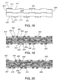
- Fig. 8 shows the bottom of the belt 100 when the top conveying surface 23 of the belt 100 is closed.
- the gaps between adjacent modules 20 are minimized and the gaps where foodstuff could pass through the belt surface are minimized.
- the opposed side walls of the link ends on adjacent modules define the hinge gap A which increases when the belt travels around a sprocket as shown in Fig. 9 .
- Fig. 10A shows the side walls 126, 129 of the longitudinal rib 101 intersect with plate-like portions 110 that extend toward the link ends along a curved path.
- the pivot rod openings 57 may be provided with an oblong shape with pivot rod openings 57 on opposite sides of the modules being oriented at equal and opposite angles. As a result, a gap is created around the pivot rod to facilitate cleaning. As shown in Fig. 11 , the gap widens as the belt passes over the sprocket.
- Fig. 10B shows an alternate embodiment of the invention with a standard rib 178 having side walls 172 and 174, a top wall 179 and extending to a flat bottom surface 170.
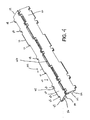
- Belt module 200 has a first side edge 201 and a second side edge 202.
- a top conveying surface 205 extends between the side edges 201, 202.
- a first plurality of link ends 203 extend from the conveying surface 205 in the direction of belt travel indicated by arrow 215.
- a second plurality of link ends 209 extend in the opposite direction. The first plurality of link ends 203 fit into the spaces between the second plurality of link ends 209 on the adjacent module 200.
- Belt module 200 has plate-like extensions 207, 220 extending from the sides of the link ends 203, 209 with an edge 208, 213 that is sized to extend approximately halfway between neighboring link ends 203, 209 creating a staggered gap when the belt 250 runs around a sprocket.
- the transversal width W of the edge 208 may of course also be another percentage of the distance between link ends 203.
- the cleaning properties remain the same for this version, but it may be of advantage for molding and load distribution to the link ends.
- Link ends 227, 229 are located at or near the side edges 201, 202.
- a center cross rib 230 may be in the center axis of the modules equally spaced to transverse pivot rod openings 235 or may be offset to either side.
- the cross rib 230 serves for engagement of sprockets to drive the belt. Further it stiffens the link connection to the module and may better accommodate the impact of heavier loads to be conveyed.
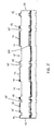
- a belt 250 constructed of modules 200 connected by pivot rods 254 is shown as it travels around a sprocket (not shown). Gaps 255 open between the plate-like extensions 207, 220 and the openings between adjacent link ends 203, 209.
- a longitudinal rib 270 is formed on bottom surface 273.
- the target is to reduce the transversal distance B to a minimum.
- This configuration of the link ends concentrates the shearing forces on the pivot rod 254 in two planes with a small distance B between them and thus avoids rod bending and reduces belt elasticity.
- the link gap of the two adjacent links must remain large enough to allow for easy cleaning.
- the link gap A is created by an angled shaping of the link ends.
- the gap A between the links is formed by opposed side walls 280, 283 on adjacent link ends being substantially parallel to each other and disposed at an angle ⁇ with respect to the other side wall 287, 288 on each link end.
- ⁇ is approximately 20 degrees.
- the side wall 287, 288 opposite to the angled side wall 280, 283 may be parallel to the direction of belt travel or alternatively may be angled as discussed herein. The configuration of the opposite side wall allows for optimization of the link shape to keep sufficient link thickness S at the rearward link end.
- Fig. 17 an alternate embodiment is shown with the link ends being shaped such that all of the side walls 292, 294, 296, and 298 are disposed parallel to each other. By arranging the side walls in this fashion the thickness T of the link end is maintained uniform on the bottom surface.
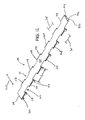
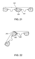
- a pair of end-to-end reversible modules 300, 301 are shown. Such modules may be used as chains, particularly in wider width, in order to eliminate the gaps between the modules in the same row of a bricklayed belt. Alternatively, modules 300, 301 may be used to build bricklayed belts.
- the modules 300, 301 have a closed top surface 308 extending from a first side edge 307 to a second side edge 309.
- a leading edge 311 includes alternating transverse portions 314 and openings 317 for receiving the transverse portions of adjacent modules.
- a trailing edge 320 includes a recessed portion 323 leading to successive transverse portions 314 and openings 317.
- link ends 303 and 306 are disposed in pairs connected by a first plate 390. Extending from leading edge 311, link ends 304 and 305 are connected by a second plate 393.
- the first 390 and second 393 plates are elongate and have a top surface 394 that is coplanar with top surface 308 of the modules 300, 301. Accordingly, the first 390 and second 393 plates are supported at both sides by the link ends. This arrangement provides the first 390 and second 393 plates with greater impact resistance.
- the modules 300, 301 may be provided with a longitudinal rib 318 ( Fig. 19 ).
- the gap between the links are in an angle ⁇ in a generally parallel relationship as shown in Fig. 25 .
- this angle is at least 20 degrees.
- the hinged links will rotate around the pivot rod 330 and the hinge gap A will increase, releasing any trapped residual matter.
- a link face 335 opposite to an angled face 340 may be parallel to the running direction of the belt as discussed above in connection with Fig. 16 or alternatively may be angled as well as best shown in Fig. 25 .
- This variation provides for optimizing the link shape to keep sufficient link thickness S at a rearward link end 360.
- a back surface 355 slopes away in the running direction of the belt ending in between the links at edge 365.
- This plate-like portion of the module defines a smooth and slightly concave back-surface 355 allowing the best possible access to inspection and cleaning of the exposed rods 330.
- the edges 365 meeting with the adjacently linked module body are shaped to open a gap A when the belt moves around a sprocket or drum for access of the cleaning fluid and easy removal of residuals collected in the hinge area.
- FIG. 20 an alternate embodiment of the module that is not end-to-end reversible and therefore cannot be bricklayed is shown.
- a pair of modules 400, 401 having link ends 403, 406 and 409, 412, respectively are connected by a pivot rod 415.
- the link ends are disposed in pairs as described above when the modules are connected and the link ends are intercalated.
Landscapes
- Engineering & Computer Science (AREA)
- Mechanical Engineering (AREA)
- Chain Conveyers (AREA)
- Belt Conveyors (AREA)
- Cleaning Implements For Floors, Carpets, Furniture, Walls, And The Like (AREA)
Claims (10)
- Module de courroie (20 ; 200), comprenant :une section intermédiaire s'étendant d'un premier bord latéral (26 ; 201) à un second bord latéral (29 ; 202) et présentant une surface d'acheminement supérieure (23 ; 205) et une surface inférieure (103 ; 273) ;une première pluralité d'extrémités de liaison (44, 65, 70 ; 203), les premières extrémités de liaison (44, 65, 70 ; 203) ayant une paire de parois latérales (50, 53) définissant une épaisseur transversale (S, T), les premières extrémités de liaison (44, 65, 70 ; 203) s'étendant à partir de la section intermédiaire dans une direction de déplacement de courroie, au moins l'une des premières extrémités de liaison (44, 65, 70 ; 203) ayant une première plaque allongée (68, 72 ; 207) s'étendant à partir de celle-ci sur une distance laissant une ouverture (45 ; 210) jusqu'à la première extrémité de liaison (44, 65, 70 ; 203) suivante, la première plaque (68, 72 ; 207) ayant une surface qui est coplanaire avec la surface d'acheminement supérieure (23 ; 205) ; etune seconde pluralité d'extrémités de liaison (44, 65, 70 ; 209), les secondes extrémités de liaison (44, 65, 70 ; 209) ayant une paire de parois latérales définissant une épaisseur transversale, les secondes extrémités de liaison (44, 65, 70 ; 209) s'étendant à partir de la section intermédiaire dans une direction opposée à la première pluralité d'extrémités de liaison (44, 65, 70 ; 203), au moins l'une des secondes extrémités de liaison (44, 65, 70 ; 209) ayant une seconde plaque allongée (68, 72 ; 220) s'étendant à partir de celle-ci sur une distance laissant une ouverture (45 ; 211) vers la deuxième extrémité de liaison (44, 65, 70 ; 209) suivante, la seconde plaque (68, 72 ; 220) ayant une surface qui est coplanaire avec la surface d'acheminement supérieure (23 ; 205) ;où les premières extrémités de liaison (44, 65, 70 ; 203) sont capables de s'adapter dans des ouvertures (45, 56, 75 ; 211) entre les secondes extrémités de liaison d'un module adjacent (20 ; 200) lorsque les modules (20 ; 200) sont intercalés pour former une courroie (100 ; 250), les premières (44, 65, 70 ; 203) et secondes extrémités de liaison de modules (20 ; 200) adjacents étant disposées à proximité les unes des autres par rapport à la direction transversale.
- Module de courroie (20 ; 200) selon la revendication 1, dans lequel le module (20 ; 200) comprend en outre une nervure longitudinale (101, 178 ; 230, 270).
- Module de courroie (20 ; 200) selon la revendication 1 ou 2, dans lequel les modules (20 ; 200) sont capables d'être disposés en briques.
- Module de courroie (20 ; 200) selon l'une quelconque des revendications 1 à 3, dans lequel le module (20 ; 200) s'étend sur toute sa largeur pour former une chaîne.
- Module de courroie (20 ; 200) selon l'une quelconque des revendications 1 à 4, dans lequel des premières (44, 65, 70 ; 203) et secondes (44, 65, 70 ; 209) extrémités de liaison ont des parois latérales qui sont disposées sensiblement parallèlement les unes aux autres.
- Module de courroie (20 ; 200) selon l'une quelconque des revendications 1 à 5, dans lequel les parois latérales des premières (44, 65, 70 ; 203) et secondes (44, 65, 70 ; 209) extrémités de liaison sont disposées selon un angle aigu.
- Module de courroie (20 ; 200) selon l'une quelconque des revendications 1 à 6, dans lequel la première extrémité de liaison (44, 65, 70 ; 203) est disposée selon un angle (β) par rapport à la direction de déplacement de courroie.
- Module de courroie (20 ; 200) selon la revendication 7, dans lequel l'angle (β) est de 15 à 30 degrés.
- Module de courroie (20 ; 200) selon la revendication 8, dans lequel l'angle (β) est d'approximativement 20 degrés.
- Courroie d'acheminement modulaire (100 ; 250), comprenant :un premier module de courroie (20 ; 200) selon l'une quelconque des revendications 1 à 9 comportant une ouverture de tige de pivotement transversale (57) s'étendant entre les deux parois latérales (50, 53) ;un second module de courroie (20 ; 200) selon l'une quelconque des revendications 1 à 9 ayant une ouverture de tige de pivotement transversale (57) s'étendant entre les parois latérales (50, 53) ; etune tige de pivotement (59 ; 254) disposée à travers les ouvertures de tige de pivotement transversales alignées (57) de modules de courroie (20 ; 200) intercalés.
Applications Claiming Priority (2)
| Application Number | Priority Date | Filing Date | Title |
|---|---|---|---|
| US11/781,405 US7530455B2 (en) | 2007-07-23 | 2007-07-23 | Module with large open hinge for easy cleaning |
| PCT/CH2008/000320 WO2009012608A1 (fr) | 2007-07-23 | 2008-07-17 | Module à grande charnière ouverte pour nettoyage facile |
Publications (2)
| Publication Number | Publication Date |
|---|---|
| EP2176144A1 EP2176144A1 (fr) | 2010-04-21 |
| EP2176144B1 true EP2176144B1 (fr) | 2011-07-06 |
Family
ID=39745098
Family Applications (1)
| Application Number | Title | Priority Date | Filing Date |
|---|---|---|---|
| EP08772891A Not-in-force EP2176144B1 (fr) | 2007-07-23 | 2008-07-17 | Module à grande charnière ouverte pour nettoyage facile |
Country Status (9)
| Country | Link |
|---|---|
| US (1) | US7530455B2 (fr) |
| EP (1) | EP2176144B1 (fr) |
| JP (1) | JP2010534175A (fr) |
| CN (1) | CN101754916A (fr) |
| AT (1) | ATE515463T1 (fr) |
| CA (1) | CA2693789A1 (fr) |
| DK (1) | DK2176144T3 (fr) |
| ES (1) | ES2368777T3 (fr) |
| WO (1) | WO2009012608A1 (fr) |
Families Citing this family (13)
| Publication number | Priority date | Publication date | Assignee | Title |
|---|---|---|---|---|
| US8678180B2 (en) * | 2012-07-25 | 2014-03-25 | Laitram, L.L.C. | Modular conveyor belt with extended raised ribs |
| US10005064B2 (en) * | 2013-11-22 | 2018-06-26 | Basf Se | Process for producing water-absorbing polymer particles |
| NL2012090C2 (nl) | 2014-01-15 | 2015-07-16 | Rexnord Flattop Europe Bv | Modulaire transportmat en module daarvoor, alsmede kettingwiel en transportsysteem. |
| US10315847B2 (en) | 2014-12-31 | 2019-06-11 | Prince Castle LLC | Extruded slat/link conveyance chain |
| US10464757B2 (en) | 2014-12-31 | 2019-11-05 | Prince Castle LLC | Sprocket driven conveyor belt link and conveyor belt assembly |
| US9889992B1 (en) * | 2015-05-13 | 2018-02-13 | Prince Castle LLC | Conveyor belt slat |
| US9908708B1 (en) | 2015-05-13 | 2018-03-06 | Prince Castle LLC | Conveyor belt link with coupling mechanism |
| EP3199477B1 (fr) | 2016-01-27 | 2019-07-17 | Prince Castle LLC | Lamelle pour une bande transporteuse à chaîne et pour un système de bande transporteuse |
| US20180000284A1 (en) * | 2016-06-29 | 2018-01-04 | Prince Castle LLC | Continuous conveyor belt for food heating device |
| US10308433B2 (en) | 2016-06-29 | 2019-06-04 | Prince Castle LLC | Conveyor belt slat with side carrier connection |
| US10723560B2 (en) | 2016-11-18 | 2020-07-28 | Prince Castle LLC | Side-by-side snap on slats for a chain conveyor belt and conveyor belt system comprising same |
| US10843871B2 (en) | 2017-12-01 | 2020-11-24 | Prince Castle LLC | Side-by-side slats for a chain conveyor belt and conveyor belt system comprising same |
| EP3733564A1 (fr) * | 2019-05-02 | 2020-11-04 | Habasit AG | Courroie transporteuse modulaire dotée de structures de guidage de fluides |
Family Cites Families (13)
| Publication number | Priority date | Publication date | Assignee | Title |
|---|---|---|---|---|
| US3269526A (en) * | 1964-08-28 | 1966-08-30 | Rex Chainbelt Inc | Chain link with improved pin securement |
| US3628834A (en) * | 1969-09-03 | 1971-12-21 | Baychem Corp | Link members and endless chains especially for tracked vehicles |
| US5125504A (en) | 1991-03-08 | 1992-06-30 | Rexnord Corporation | Modular conveyor chain having open hinge pin construction |
| US5339946A (en) * | 1992-11-16 | 1994-08-23 | William G. Faulkner | Conveyor belt having link assemblies with leading and trailing shaft projections |
| US5706934A (en) | 1994-11-14 | 1998-01-13 | Kvp Systems, Inc. | Modular solid top plastic conveyor belt |
| AU135536S (en) * | 1997-04-02 | 1998-11-02 | Singapore Tech Kinetics Ltd | A tracked link |
| US6725883B2 (en) | 2001-06-05 | 2004-04-27 | Habasit Ag | Flat top open hinge module |
| US6758329B1 (en) | 2003-02-10 | 2004-07-06 | Uni-Chains A/S | Wide chain link conveyor structure |
| US7267221B2 (en) * | 2003-04-28 | 2007-09-11 | Ramsey Products Corporation | Silent modular conveyor and conveyor links |
| US6811023B1 (en) * | 2003-05-22 | 2004-11-02 | Laitram, L.L.C. | Modular trough conveyor belt and modules |
| US6997308B2 (en) * | 2004-07-12 | 2006-02-14 | Laitram, L.L.C. | Welded conveyor belt modules, belts made of welded modules, and method of making welded modules |
| US7367448B2 (en) * | 2006-07-20 | 2008-05-06 | Habasit Ag | Chain with undulated edge |
| US8276747B2 (en) | 2007-06-29 | 2012-10-02 | Habasit Ag | Module for a modular belt and a driving sprocket for easy cleaning |
-
2007
- 2007-07-23 US US11/781,405 patent/US7530455B2/en not_active Expired - Fee Related
-
2008
- 2008-07-17 JP JP2010517248A patent/JP2010534175A/ja not_active Withdrawn
- 2008-07-17 DK DK08772891.1T patent/DK2176144T3/da active
- 2008-07-17 CA CA2693789A patent/CA2693789A1/fr not_active Abandoned
- 2008-07-17 WO PCT/CH2008/000320 patent/WO2009012608A1/fr active Application Filing
- 2008-07-17 ES ES08772891T patent/ES2368777T3/es active Active
- 2008-07-17 AT AT08772891T patent/ATE515463T1/de active
- 2008-07-17 CN CN200880025230A patent/CN101754916A/zh active Pending
- 2008-07-17 EP EP08772891A patent/EP2176144B1/fr not_active Not-in-force
Also Published As
| Publication number | Publication date |
|---|---|
| CN101754916A (zh) | 2010-06-23 |
| US7530455B2 (en) | 2009-05-12 |
| ATE515463T1 (de) | 2011-07-15 |
| EP2176144A1 (fr) | 2010-04-21 |
| ES2368777T3 (es) | 2011-11-22 |
| JP2010534175A (ja) | 2010-11-04 |
| WO2009012608A1 (fr) | 2009-01-29 |
| DK2176144T3 (da) | 2011-08-29 |
| US20090026048A1 (en) | 2009-01-29 |
| CA2693789A1 (fr) | 2009-01-29 |
Similar Documents
| Publication | Publication Date | Title |
|---|---|---|
| EP2176144B1 (fr) | Module à grande charnière ouverte pour nettoyage facile | |
| EP1799596B1 (fr) | Module de bande a trou de pivot oblong | |
| US7367448B2 (en) | Chain with undulated edge | |
| US5706934A (en) | Modular solid top plastic conveyor belt | |
| EP1277676B1 (fr) | Panneau latéral pour convoyeurs avec mécanisme de fermeture cliquetant | |
| EP1300349B1 (fr) | Bande transporteuse modulaire avec accessoires retenus par des tiges | |
| EP1182151B1 (fr) | Transporteur à bande courbée | |
| EP1264786B1 (fr) | Elément plat pour convoyeurs modulaires | |
| US6948613B2 (en) | Module with high friction conveying surface | |
| US6305530B1 (en) | Module for a modular conveying belt | |
| EP2170744B1 (fr) | Module pour une courroie modulaire et pignon d'entraînement pour nettoyage facile | |
| NL2002344C2 (en) | Conveyor chain module, conveyor chain, conveyor and conveyor system. | |
| EP1270454A1 (fr) | Module d'une bande transporteuse avec grille lisse | |
| CA2380139C (fr) | Courroie de transport radial avec structure evitant le pincement des griffes | |
| EP1174371B1 (fr) | Bande transporteuse a rayon modulaire | |
| US9540177B1 (en) | Conveyor belt and modules with flights at the hinge |
Legal Events
| Date | Code | Title | Description |
|---|---|---|---|
| PUAI | Public reference made under article 153(3) epc to a published international application that has entered the european phase |
Free format text: ORIGINAL CODE: 0009012 |
|
| 17P | Request for examination filed |
Effective date: 20100127 |
|
| AK | Designated contracting states |
Kind code of ref document: A1 Designated state(s): AT BE BG CH CY CZ DE DK EE ES FI FR GB GR HR HU IE IS IT LI LT LU LV MC MT NL NO PL PT RO SE SI SK TR |
|
| AX | Request for extension of the european patent |
Extension state: AL BA MK RS |
|
| 17Q | First examination report despatched |
Effective date: 20100625 |
|
| DAX | Request for extension of the european patent (deleted) | ||
| GRAP | Despatch of communication of intention to grant a patent |
Free format text: ORIGINAL CODE: EPIDOSNIGR1 |
|
| RIN1 | Information on inventor provided before grant (corrected) |
Inventor name: LUCCHI, MARCO |
|
| GRAS | Grant fee paid |
Free format text: ORIGINAL CODE: EPIDOSNIGR3 |
|
| GRAA | (expected) grant |
Free format text: ORIGINAL CODE: 0009210 |
|
| AK | Designated contracting states |
Kind code of ref document: B1 Designated state(s): AT BE BG CH CY CZ DE DK EE ES FI FR GB GR HR HU IE IS IT LI LT LU LV MC MT NL NO PL PT RO SE SI SK TR |
|
| REG | Reference to a national code |
Ref country code: GB Ref legal event code: FG4D |
|
| REG | Reference to a national code |
Ref country code: CH Ref legal event code: EP |
|
| REG | Reference to a national code |
Ref country code: IE Ref legal event code: FG4D |
|
| REG | Reference to a national code |
Ref country code: DE Ref legal event code: R096 Ref document number: 602008008118 Country of ref document: DE Effective date: 20110825 |
|
| REG | Reference to a national code |
Ref country code: DK Ref legal event code: T3 |
|
| REG | Reference to a national code |
Ref country code: NL Ref legal event code: T3 |
|
| REG | Reference to a national code |
Ref country code: SE Ref legal event code: TRGR |
|
| PGFP | Annual fee paid to national office [announced via postgrant information from national office to epo] |
Ref country code: DK Payment date: 20110726 Year of fee payment: 4 |
|
| REG | Reference to a national code |
Ref country code: ES Ref legal event code: FG2A Ref document number: 2368777 Country of ref document: ES Kind code of ref document: T3 Effective date: 20111122 |
|
| PG25 | Lapsed in a contracting state [announced via postgrant information from national office to epo] |
Ref country code: SI Free format text: LAPSE BECAUSE OF FAILURE TO SUBMIT A TRANSLATION OF THE DESCRIPTION OR TO PAY THE FEE WITHIN THE PRESCRIBED TIME-LIMIT Effective date: 20110706 |
|
| PGFP | Annual fee paid to national office [announced via postgrant information from national office to epo] |
Ref country code: ES Payment date: 20110720 Year of fee payment: 4 Ref country code: DE Payment date: 20110831 Year of fee payment: 4 Ref country code: FR Payment date: 20110811 Year of fee payment: 4 |
|
| PG25 | Lapsed in a contracting state [announced via postgrant information from national office to epo] |
Ref country code: MT Free format text: LAPSE BECAUSE OF FAILURE TO SUBMIT A TRANSLATION OF THE DESCRIPTION OR TO PAY THE FEE WITHIN THE PRESCRIBED TIME-LIMIT Effective date: 20110706 |
|
| PGFP | Annual fee paid to national office [announced via postgrant information from national office to epo] |
Ref country code: NL Payment date: 20110727 Year of fee payment: 4 |
|
| PG25 | Lapsed in a contracting state [announced via postgrant information from national office to epo] |
Ref country code: NO Free format text: LAPSE BECAUSE OF FAILURE TO SUBMIT A TRANSLATION OF THE DESCRIPTION OR TO PAY THE FEE WITHIN THE PRESCRIBED TIME-LIMIT Effective date: 20111006 Ref country code: FI Free format text: LAPSE BECAUSE OF FAILURE TO SUBMIT A TRANSLATION OF THE DESCRIPTION OR TO PAY THE FEE WITHIN THE PRESCRIBED TIME-LIMIT Effective date: 20110706 Ref country code: IS Free format text: LAPSE BECAUSE OF FAILURE TO SUBMIT A TRANSLATION OF THE DESCRIPTION OR TO PAY THE FEE WITHIN THE PRESCRIBED TIME-LIMIT Effective date: 20111106 Ref country code: BE Free format text: LAPSE BECAUSE OF FAILURE TO SUBMIT A TRANSLATION OF THE DESCRIPTION OR TO PAY THE FEE WITHIN THE PRESCRIBED TIME-LIMIT Effective date: 20110706 Ref country code: PT Free format text: LAPSE BECAUSE OF FAILURE TO SUBMIT A TRANSLATION OF THE DESCRIPTION OR TO PAY THE FEE WITHIN THE PRESCRIBED TIME-LIMIT Effective date: 20111107 Ref country code: LT Free format text: LAPSE BECAUSE OF FAILURE TO SUBMIT A TRANSLATION OF THE DESCRIPTION OR TO PAY THE FEE WITHIN THE PRESCRIBED TIME-LIMIT Effective date: 20110706 Ref country code: HR Free format text: LAPSE BECAUSE OF FAILURE TO SUBMIT A TRANSLATION OF THE DESCRIPTION OR TO PAY THE FEE WITHIN THE PRESCRIBED TIME-LIMIT Effective date: 20110706 |
|
| PG25 | Lapsed in a contracting state [announced via postgrant information from national office to epo] |
Ref country code: GR Free format text: LAPSE BECAUSE OF FAILURE TO SUBMIT A TRANSLATION OF THE DESCRIPTION OR TO PAY THE FEE WITHIN THE PRESCRIBED TIME-LIMIT Effective date: 20111007 Ref country code: CY Free format text: LAPSE BECAUSE OF FAILURE TO SUBMIT A TRANSLATION OF THE DESCRIPTION OR TO PAY THE FEE WITHIN THE PRESCRIBED TIME-LIMIT Effective date: 20110706 Ref country code: MC Free format text: LAPSE BECAUSE OF NON-PAYMENT OF DUE FEES Effective date: 20110731 Ref country code: PL Free format text: LAPSE BECAUSE OF FAILURE TO SUBMIT A TRANSLATION OF THE DESCRIPTION OR TO PAY THE FEE WITHIN THE PRESCRIBED TIME-LIMIT Effective date: 20110706 Ref country code: LV Free format text: LAPSE BECAUSE OF FAILURE TO SUBMIT A TRANSLATION OF THE DESCRIPTION OR TO PAY THE FEE WITHIN THE PRESCRIBED TIME-LIMIT Effective date: 20110706 |
|
| REG | Reference to a national code |
Ref country code: IE Ref legal event code: MM4A |
|
| PG25 | Lapsed in a contracting state [announced via postgrant information from national office to epo] |
Ref country code: CZ Free format text: LAPSE BECAUSE OF FAILURE TO SUBMIT A TRANSLATION OF THE DESCRIPTION OR TO PAY THE FEE WITHIN THE PRESCRIBED TIME-LIMIT Effective date: 20110706 Ref country code: SK Free format text: LAPSE BECAUSE OF FAILURE TO SUBMIT A TRANSLATION OF THE DESCRIPTION OR TO PAY THE FEE WITHIN THE PRESCRIBED TIME-LIMIT Effective date: 20110706 |
|
| PLBE | No opposition filed within time limit |
Free format text: ORIGINAL CODE: 0009261 |
|
| STAA | Information on the status of an ep patent application or granted ep patent |
Free format text: STATUS: NO OPPOSITION FILED WITHIN TIME LIMIT |
|
| PG25 | Lapsed in a contracting state [announced via postgrant information from national office to epo] |
Ref country code: RO Free format text: LAPSE BECAUSE OF FAILURE TO SUBMIT A TRANSLATION OF THE DESCRIPTION OR TO PAY THE FEE WITHIN THE PRESCRIBED TIME-LIMIT Effective date: 20110706 Ref country code: EE Free format text: LAPSE BECAUSE OF FAILURE TO SUBMIT A TRANSLATION OF THE DESCRIPTION OR TO PAY THE FEE WITHIN THE PRESCRIBED TIME-LIMIT Effective date: 20110706 |
|
| 26N | No opposition filed |
Effective date: 20120411 |
|
| PG25 | Lapsed in a contracting state [announced via postgrant information from national office to epo] |
Ref country code: IE Free format text: LAPSE BECAUSE OF NON-PAYMENT OF DUE FEES Effective date: 20110717 |
|
| REG | Reference to a national code |
Ref country code: DE Ref legal event code: R097 Ref document number: 602008008118 Country of ref document: DE Effective date: 20120411 |
|
| REG | Reference to a national code |
Ref country code: NL Ref legal event code: V1 Effective date: 20130201 |
|
| REG | Reference to a national code |
Ref country code: CH Ref legal event code: PL |
|
| REG | Reference to a national code |
Ref country code: SE Ref legal event code: EUG |
|
| GBPC | Gb: european patent ceased through non-payment of renewal fee |
Effective date: 20120717 |
|
| REG | Reference to a national code |
Ref country code: DK Ref legal event code: EBP |
|
| REG | Reference to a national code |
Ref country code: FR Ref legal event code: ST Effective date: 20130329 |
|
| PG25 | Lapsed in a contracting state [announced via postgrant information from national office to epo] |
Ref country code: FR Free format text: LAPSE BECAUSE OF NON-PAYMENT OF DUE FEES Effective date: 20120731 Ref country code: GB Free format text: LAPSE BECAUSE OF NON-PAYMENT OF DUE FEES Effective date: 20120717 Ref country code: SE Free format text: LAPSE BECAUSE OF NON-PAYMENT OF DUE FEES Effective date: 20120718 Ref country code: CH Free format text: LAPSE BECAUSE OF NON-PAYMENT OF DUE FEES Effective date: 20120731 Ref country code: DE Free format text: LAPSE BECAUSE OF NON-PAYMENT OF DUE FEES Effective date: 20130201 Ref country code: LI Free format text: LAPSE BECAUSE OF NON-PAYMENT OF DUE FEES Effective date: 20120731 Ref country code: NL Free format text: LAPSE BECAUSE OF NON-PAYMENT OF DUE FEES Effective date: 20130201 |
|
| REG | Reference to a national code |
Ref country code: DE Ref legal event code: R119 Ref document number: 602008008118 Country of ref document: DE Effective date: 20130201 |
|
| PG25 | Lapsed in a contracting state [announced via postgrant information from national office to epo] |
Ref country code: LU Free format text: LAPSE BECAUSE OF NON-PAYMENT OF DUE FEES Effective date: 20110717 Ref country code: IT Free format text: LAPSE BECAUSE OF NON-PAYMENT OF DUE FEES Effective date: 20120717 |
|
| PG25 | Lapsed in a contracting state [announced via postgrant information from national office to epo] |
Ref country code: BG Free format text: LAPSE BECAUSE OF FAILURE TO SUBMIT A TRANSLATION OF THE DESCRIPTION OR TO PAY THE FEE WITHIN THE PRESCRIBED TIME-LIMIT Effective date: 20111006 |
|
| PG25 | Lapsed in a contracting state [announced via postgrant information from national office to epo] |
Ref country code: DK Free format text: LAPSE BECAUSE OF NON-PAYMENT OF DUE FEES Effective date: 20120731 |
|
| PG25 | Lapsed in a contracting state [announced via postgrant information from national office to epo] |
Ref country code: TR Free format text: LAPSE BECAUSE OF FAILURE TO SUBMIT A TRANSLATION OF THE DESCRIPTION OR TO PAY THE FEE WITHIN THE PRESCRIBED TIME-LIMIT Effective date: 20110706 |
|
| REG | Reference to a national code |
Ref country code: ES Ref legal event code: FD2A Effective date: 20131018 |
|
| PG25 | Lapsed in a contracting state [announced via postgrant information from national office to epo] |
Ref country code: HU Free format text: LAPSE BECAUSE OF FAILURE TO SUBMIT A TRANSLATION OF THE DESCRIPTION OR TO PAY THE FEE WITHIN THE PRESCRIBED TIME-LIMIT Effective date: 20110706 Ref country code: ES Free format text: LAPSE BECAUSE OF NON-PAYMENT OF DUE FEES Effective date: 20120718 |
|
| REG | Reference to a national code |
Ref country code: AT Ref legal event code: MM01 Ref document number: 515463 Country of ref document: AT Kind code of ref document: T Effective date: 20130717 |
|
| PG25 | Lapsed in a contracting state [announced via postgrant information from national office to epo] |
Ref country code: AT Free format text: LAPSE BECAUSE OF NON-PAYMENT OF DUE FEES Effective date: 20130717 |