EP2175708A1 - Electronic module with heat sink - Google Patents
Electronic module with heat sink Download PDFInfo
- Publication number
- EP2175708A1 EP2175708A1 EP09170763A EP09170763A EP2175708A1 EP 2175708 A1 EP2175708 A1 EP 2175708A1 EP 09170763 A EP09170763 A EP 09170763A EP 09170763 A EP09170763 A EP 09170763A EP 2175708 A1 EP2175708 A1 EP 2175708A1
- Authority
- EP
- European Patent Office
- Prior art keywords
- housing
- heat sink
- electronic module
- port
- base
- Prior art date
- Legal status (The legal status is an assumption and is not a legal conclusion. Google has not performed a legal analysis and makes no representation as to the accuracy of the status listed.)
- Granted
Links
Images
Classifications
-
- H—ELECTRICITY
- H05—ELECTRIC TECHNIQUES NOT OTHERWISE PROVIDED FOR
- H05K—PRINTED CIRCUITS; CASINGS OR CONSTRUCTIONAL DETAILS OF ELECTRIC APPARATUS; MANUFACTURE OF ASSEMBLAGES OF ELECTRICAL COMPONENTS
- H05K7/00—Constructional details common to different types of electric apparatus
- H05K7/20—Modifications to facilitate cooling, ventilating, or heating
- H05K7/2039—Modifications to facilitate cooling, ventilating, or heating characterised by the heat transfer by conduction from the heat generating element to a dissipating body
- H05K7/20409—Outer radiating structures on heat dissipating housings, e.g. fins integrated with the housing
-
- H—ELECTRICITY
- H05—ELECTRIC TECHNIQUES NOT OTHERWISE PROVIDED FOR
- H05K—PRINTED CIRCUITS; CASINGS OR CONSTRUCTIONAL DETAILS OF ELECTRIC APPARATUS; MANUFACTURE OF ASSEMBLAGES OF ELECTRICAL COMPONENTS
- H05K7/00—Constructional details common to different types of electric apparatus
- H05K7/20—Modifications to facilitate cooling, ventilating, or heating
- H05K7/2039—Modifications to facilitate cooling, ventilating, or heating characterised by the heat transfer by conduction from the heat generating element to a dissipating body
- H05K7/20436—Inner thermal coupling elements in heat dissipating housings, e.g. protrusions or depressions integrally formed in the housing
- H05K7/20445—Inner thermal coupling elements in heat dissipating housings, e.g. protrusions or depressions integrally formed in the housing the coupling element being an additional piece, e.g. thermal standoff
-
- H—ELECTRICITY
- H10—SEMICONDUCTOR DEVICES; ELECTRIC SOLID-STATE DEVICES NOT OTHERWISE PROVIDED FOR
- H10W—GENERIC PACKAGES, INTERCONNECTIONS, CONNECTORS OR OTHER CONSTRUCTIONAL DETAILS OF DEVICES COVERED BY CLASS H10
- H10W40/00—Arrangements for thermal protection or thermal control
- H10W40/20—Arrangements for cooling
- H10W40/22—Arrangements for cooling characterised by their shape, e.g. having conical or cylindrical projections
-
- H—ELECTRICITY
- H10—SEMICONDUCTOR DEVICES; ELECTRIC SOLID-STATE DEVICES NOT OTHERWISE PROVIDED FOR
- H10W—GENERIC PACKAGES, INTERCONNECTIONS, CONNECTORS OR OTHER CONSTRUCTIONAL DETAILS OF DEVICES COVERED BY CLASS H10
- H10W40/00—Arrangements for thermal protection or thermal control
- H10W40/60—Securing means for detachable heating or cooling arrangements, e.g. clamps
- H10W40/611—Bolts or screws
-
- H—ELECTRICITY
- H10—SEMICONDUCTOR DEVICES; ELECTRIC SOLID-STATE DEVICES NOT OTHERWISE PROVIDED FOR
- H10W—GENERIC PACKAGES, INTERCONNECTIONS, CONNECTORS OR OTHER CONSTRUCTIONAL DETAILS OF DEVICES COVERED BY CLASS H10
- H10W40/00—Arrangements for thermal protection or thermal control
- H10W40/20—Arrangements for cooling
- H10W40/231—Arrangements for cooling characterised by their places of attachment or cooling paths
- H10W40/242—Arrangements for cooling characterised by their places of attachment or cooling paths comprising thermal conductors between chips and the and the arrangements for cooling, e.g. compliant heat-spreaders
-
- H—ELECTRICITY
- H10—SEMICONDUCTOR DEVICES; ELECTRIC SOLID-STATE DEVICES NOT OTHERWISE PROVIDED FOR
- H10W—GENERIC PACKAGES, INTERCONNECTIONS, CONNECTORS OR OTHER CONSTRUCTIONAL DETAILS OF DEVICES COVERED BY CLASS H10
- H10W40/00—Arrangements for thermal protection or thermal control
- H10W40/60—Securing means for detachable heating or cooling arrangements, e.g. clamps
Definitions
- the invention relates to an electronic module, configured to be mounted on a base, and housing a heat producing electrical component. More particularly, the invention comprises an insulating housing with an embedded heat sink for convective dissipation of heat and a conductive runner extending from the heat sink to the port for conductive dissipation of heat.
- the port is coupled to the base structure, providing both a conductive heat sink and an electrical ground.
- PCB printed circuit board
- the enclosure includes a thermal heat sink to prevent overheating of the electrical components.
- Metal enclosures with heat sinks although efficient at removing heat, are less amenable to the intricate geometries that are desirable for electronic enclosures.
- Plastic enclosures are poor conductors of heat and are not as efficient at removing excess heat from heat producing electrical components. It is desired to have an electronic enclosure, made of a thermally insulating material such as plastic, which provides mechanisms for heat sinking and electrically grounding electrical components on a PCB.
- an electronic module comprises a housing formed at least partially of an insulating material which includes a wall and a means for mounting the housing to a conductive base.
- the module further includes a heat sink adjacent a heat producing electrical component within the housing. The heat sink conducts thermal energy from the component and expels it by thermal convection external the housing.
- the module also includes a thermally conductive port on the exterior surface of the housing, which is coupled to the conductive base.
- a thermally conductive runner insert molded in the wall of the housing connects the heat sink with the port. This runner provides a thermal conduction path between the housing and the base to further expel heat from the heat producing electronic device.
- an electronic module comprises a housing formed at least partially of an insulating material.
- the housing includes a means for mounting the housing to a conductive base including a thermally conducting port on the external surface of the housing.
- the port is configured to accept the integrally formed mounting means of the base, enabling thermal energy transfer from the port to the base.
- the housing further includes a heat sink having a contact surface and a thermally conductive material disposed between the heat producing electrical component and the contact surface to enhance heat transfer.
- the heat sink also comprises fins, located opposite the contact surface and external the housing, to dissipate heat by thermal convection.
- the electronic module comprises a thermally conductive runner interconnecting the heat sink and the port to conduct heat from the heat sink in the housing to the conductive base.
- the runner is at least partially embedded in the wall of the housing.
- an electronic module comprises a housing formed at least partially of an injection molded thermoplastic material which includes a wall and a means for mounting the housing to a conductive base.
- a printed circuit board with at least one electrical ground lead is disposed inside the housing.
- An electrical connector disposed within the housing is in contact with the electrical ground lead on the PCB.
- the housing also comprises an electrically conductive port on the external surface of the housing. This port is configured to accept the integrally formed mounting means of the base, enabling electrical grounding from the port to the base.
- the electronic module further includes an electrically conductive runner at least partially insert molded within the wall of the housing. The runner interconnects the electrical connector and the port and provides an electrical ground path from the printed circuit board to the base.
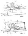
- Fig. 1 is a broken, perspective, exploded view of the electronic module with the plastic case removed;
- Fig. 2 is a perspective view of the electronic module attached to the base.
- an electronic module 10 is comprised of a housing 12, made at least partially of an insulating material such as plastic, mounted to a conductive base 14.
- the base is preferably made of metal and comprises a lug 16 to accept mounting means 18 defined by the housing.
- the base 14 provides mechanical support for the housing 12 when it is secured using a lug nut 20.
- the lug 16 is integrally formed on the base which, in combination with lug nut 20, provides suitable means for connecting the base 14 to the electronic module 10.
- any means of connecting the housing to the base would be acceptable.
- the mounting means 18 of the housing 12 comprises a thermally conductive port 22.
- the port 22 is made of metal and provides enhanced structural integrity to the mounting means of the housing 12.
- the electronic module 10 also comprises a printed circuit board 24, with at least one heat producing electrical component 26, enclosed within the housing 12.
- the printed circuit board 24 physically supports the electrical component 26 and provides an electric circuit 28 to operate all the components on the circuit board. Any other suitable substrate, including ceramic substrates, could be substituted for the printed circuit board in this invention.
- the heat producing electrical component 26 is adjacent a heat sink 30, with thermally conductive material 32 disposed between the component 26 and the heat sink 30. Heat generated by the component 26 is transferred by thermal conduction through the thermally conductive material 32 into the foundation 34 of the heat sink. Heat is then transferred by thermal conduction from the foundation 34 to heat sink fins 36, where it is dissipated by thermal convection due to fluid flow across the fins 36.
- the heat sink 30 is preferably made of a metal with high thermal conductivity and is insert molded into the housing 12 so as to align the foundation 34 with the heat producing electrical component 26.
- Thermally conductive material 32 is used to enhance thermal conduction between the component 26 and the heat sink foundation 34.
- the fins 36 are disposed on the exterior of the housing to enable fluid flow for convective cooling.
- a conductive runner 38 is integrally formed connecting the heat sink foundation 34 and the port 22.
- the runner 38 is formed of a metal with high thermal conductivity, preferably the same metal as the heat sink 30 and the port 22.
- the runner is at least partially embedded in the plastic housing 12.
- the conductive runner 38 enables a thermal conduction path from the heat producing electrical component 26, through the thermally conductive material 32, the heat sink foundation 34, the thermally conductive runner 38, the port 22, and the lug 16 to the base 18. This feature allows for a second heat sinking path from the component 26 to the base 18.
- this invention provides an electronic module, including a housing containing a printed circuit board with a heat producing electronic component.
- the housing has a mounting means for connecting to a conductive base.
- the mounting means provides structural support for the housing as well as a conductive port integrated into the mounting means.
- the conductive port is integrally formed with a conductive runner connecting the port and the foundation of a heat sink.
- the heat sink foundation is disposed adjacent the heat producing electronic component with a thermal conductive material therebetween. Heat from the heat producing electronic component is dissipated by conduction through the thermal conductive material to the heat sink foundation. From the heat sink foundation the heat may travel in one of two possible paths.
- the first path is from the heat sink foundation to the heat sink fins, which are disposed external the housing and are configured to dissipate the heat by convection to the external fluid flow.
- the second path is from the heat sink foundation through the conductive runner, the port, the lug and finally to the conductive base.
- the conductive runner enables a second conduction path for heat transfer out of the heat producing electronic component, increasing the efficiency of cooling the component, and increasing the reliability of the electronic module.
- Housing 12 is formed by injection molding an insulating plastic material using a mold having the specific size and shape for receiving the heat producing electrical component 26.
- the metal port 22 Prior to injection of the plastic material, the metal port 22 is placed in the locater section of the mold to ensure proper alignment of the conductive runner 38 and the heat sink 30.
- the locater section of the mold is the area that will form the mounting means 18 in the electronic module.
- the port 22, runner 38, and heat sink 30 are all one integral piece of conductive metal material.
- the insulating plastic material is injected into the mold, encasing a portion of both the thermally conductive runner 38 and heat sink foundation 34, and creating a cavity in which the printed circuit board 24 can be installed.
- a thermally conductive material 32 is applied to the bottom surface of the heat sink foundation 34 and the printed circuit board 24 is installed in the housing 12 so that the thermally conductive material 32 is disposed between the component 26 and the heat sink foundation 34.
- an electronic module 10 is comprised of a housing 12, made at least partially of an insulating material such as plastic, mounted to a conductive base 14.
- the base 14 is preferably made of metal and comprises a lug 16 to accept the mounting means 18 of the housing.
- the base 14 provides mechanical support for the housing 12 when it is secured with lug nut 20.
- a lug integrally formed on the base, in combination with a lug nut, provides suitable means for connecting the base to the electronic module, however any means of connecting the housing to the base would be acceptable.
- the mounting means 18 of the housing 12 comprises an electrically conductive port 22.
- the port 22 is made of metal and provides enhanced structural integrity to the mounting means of the housing.
- the electronic module 10 also comprises a printed circuit board 24, with at least one electrical ground lead 40, enclosed within the housing 12.
- the printed circuit board 24 provides the electric circuit 28 to operate all the components on the circuit board 24. Any other suitable substrate, including ceramic substrates, could be substituted for the printed circuit board in this invention.
- the electrical ground lead 40 is adjacent electrical connector 42, to facilitate electrical grounding of the printed circuit board 24.
- a conductive runner 38 is integrally formed connecting the electrical ground lead 40 and the port 24.
- the conductive runner 38 is formed of a metal, preferably the same metal as the electrical ground lead 40 and the port 24.
- the runner 38 is at least partially embedded in the plastic housing 12.
- the conductive runner 38 enables an electrical grounding path from the electrical connector 42, through the conductive runner 38, the port 22, and the lug 16 to the base 18. This feature allows for an electrical grounding path from the printed circuit board 24 to the base 18.
- this embodiment provides an alternative use for the conductive runner connecting the heat sink and the base. It may be desirable to use a conductive path from the printed circuit board and the components on the printed circuit board for both a heat sink and an electrical ground path.
- the printed circuit board and the heat producing components on the printed circuit board may be located within the housing.
- the conductive runner would allow for conductive heat dissipation from the component to the base external the housing.
- the conductive runner would also allow for an electrical ground path from the circuit on the printed circuit board to the base external the housing.
Landscapes
- Physics & Mathematics (AREA)
- Thermal Sciences (AREA)
- Engineering & Computer Science (AREA)
- Microelectronics & Electronic Packaging (AREA)
- Cooling Or The Like Of Electrical Apparatus (AREA)
Abstract
Description
- The invention relates to an electronic module, configured to be mounted on a base, and housing a heat producing electrical component. More particularly, the invention comprises an insulating housing with an embedded heat sink for convective dissipation of heat and a conductive runner extending from the heat sink to the port for conductive dissipation of heat. The port is coupled to the base structure, providing both a conductive heat sink and an electrical ground.
- It is known to package a printed circuit board (PCB) with heat producing electrical components in an electronic enclosure. The enclosure includes a thermal heat sink to prevent overheating of the electrical components. Metal enclosures with heat sinks, although efficient at removing heat, are less amenable to the intricate geometries that are desirable for electronic enclosures. Plastic enclosures are poor conductors of heat and are not as efficient at removing excess heat from heat producing electrical components. It is desired to have an electronic enclosure, made of a thermally insulating material such as plastic, which provides mechanisms for heat sinking and electrically grounding electrical components on a PCB.
- In accordance with this invention, an electronic module comprises a housing formed at least partially of an insulating material which includes a wall and a means for mounting the housing to a conductive base. The module further includes a heat sink adjacent a heat producing electrical component within the housing. The heat sink conducts thermal energy from the component and expels it by thermal convection external the housing. The module also includes a thermally conductive port on the exterior surface of the housing, which is coupled to the conductive base. A thermally conductive runner insert molded in the wall of the housing connects the heat sink with the port. This runner provides a thermal conduction path between the housing and the base to further expel heat from the heat producing electronic device.
- In one aspect of the invention, an electronic module comprises a housing formed at least partially of an insulating material. The housing includes a means for mounting the housing to a conductive base including a thermally conducting port on the external surface of the housing. The port is configured to accept the integrally formed mounting means of the base, enabling thermal energy transfer from the port to the base. The housing further includes a heat sink having a contact surface and a thermally conductive material disposed between the heat producing electrical component and the contact surface to enhance heat transfer. The heat sink also comprises fins, located opposite the contact surface and external the housing, to dissipate heat by thermal convection. Finally, the electronic module comprises a thermally conductive runner interconnecting the heat sink and the port to conduct heat from the heat sink in the housing to the conductive base. The runner is at least partially embedded in the wall of the housing.
- In another aspect of this invention, an electronic module comprises a housing formed at least partially of an injection molded thermoplastic material which includes a wall and a means for mounting the housing to a conductive base. A printed circuit board with at least one electrical ground lead is disposed inside the housing. An electrical connector disposed within the housing is in contact with the electrical ground lead on the PCB. The housing also comprises an electrically conductive port on the external surface of the housing. This port is configured to accept the integrally formed mounting means of the base, enabling electrical grounding from the port to the base. The electronic module further includes an electrically conductive runner at least partially insert molded within the wall of the housing. The runner interconnects the electrical connector and the port and provides an electrical ground path from the printed circuit board to the base.
- Further features and advantages of the invention will appear more clearly on a reading of the following detailed description of the preferred embodiment of the invention, which is given by way of non-limiting example only and with reference to the accompanying drawings.
- This invention will be further described with reference to the accompanying drawings in which:
-
Fig. 1 is a broken, perspective, exploded view of the electronic module with the plastic case removed; and -
Fig. 2 is a perspective view of the electronic module attached to the base. - In accordance with a preferred embodiment of this invention, referring to
Figs. 1 and 2 , anelectronic module 10 is comprised of ahousing 12, made at least partially of an insulating material such as plastic, mounted to aconductive base 14. The base is preferably made of metal and comprises alug 16 to accept mounting means 18 defined by the housing. Thebase 14 provides mechanical support for thehousing 12 when it is secured using alug nut 20. Thelug 16 is integrally formed on the base which, in combination withlug nut 20, provides suitable means for connecting thebase 14 to theelectronic module 10. However, any means of connecting the housing to the base would be acceptable. The mounting means 18 of thehousing 12 comprises a thermallyconductive port 22. Theport 22 is made of metal and provides enhanced structural integrity to the mounting means of thehousing 12. - The
electronic module 10 also comprises a printedcircuit board 24, with at least one heat producingelectrical component 26, enclosed within thehousing 12. The printedcircuit board 24 physically supports theelectrical component 26 and provides anelectric circuit 28 to operate all the components on the circuit board. Any other suitable substrate, including ceramic substrates, could be substituted for the printed circuit board in this invention. The heat producingelectrical component 26 is adjacent aheat sink 30, with thermallyconductive material 32 disposed between thecomponent 26 and theheat sink 30. Heat generated by thecomponent 26 is transferred by thermal conduction through the thermallyconductive material 32 into thefoundation 34 of the heat sink. Heat is then transferred by thermal conduction from thefoundation 34 toheat sink fins 36, where it is dissipated by thermal convection due to fluid flow across thefins 36. Theheat sink 30 is preferably made of a metal with high thermal conductivity and is insert molded into thehousing 12 so as to align thefoundation 34 with the heat producingelectrical component 26. Thermallyconductive material 32 is used to enhance thermal conduction between thecomponent 26 and theheat sink foundation 34. Thefins 36 are disposed on the exterior of the housing to enable fluid flow for convective cooling. - A
conductive runner 38 is integrally formed connecting theheat sink foundation 34 and theport 22. Therunner 38 is formed of a metal with high thermal conductivity, preferably the same metal as theheat sink 30 and theport 22. The runner is at least partially embedded in theplastic housing 12. Theconductive runner 38 enables a thermal conduction path from the heat producingelectrical component 26, through the thermallyconductive material 32, theheat sink foundation 34, the thermallyconductive runner 38, theport 22, and thelug 16 to thebase 18. This feature allows for a second heat sinking path from thecomponent 26 to thebase 18. - Thus, this invention provides an electronic module, including a housing containing a printed circuit board with a heat producing electronic component. The housing has a mounting means for connecting to a conductive base. The mounting means provides structural support for the housing as well as a conductive port integrated into the mounting means. The conductive port is integrally formed with a conductive runner connecting the port and the foundation of a heat sink. The heat sink foundation is disposed adjacent the heat producing electronic component with a thermal conductive material therebetween. Heat from the heat producing electronic component is dissipated by conduction through the thermal conductive material to the heat sink foundation. From the heat sink foundation the heat may travel in one of two possible paths. The first path is from the heat sink foundation to the heat sink fins, which are disposed external the housing and are configured to dissipate the heat by convection to the external fluid flow. The second path is from the heat sink foundation through the conductive runner, the port, the lug and finally to the conductive base. The conductive runner enables a second conduction path for heat transfer out of the heat producing electronic component, increasing the efficiency of cooling the component, and increasing the reliability of the electronic module.
- The manufacture of
electronic module 10 will now be described.Housing 12 is formed by injection molding an insulating plastic material using a mold having the specific size and shape for receiving the heat producingelectrical component 26. Prior to injection of the plastic material, themetal port 22 is placed in the locater section of the mold to ensure proper alignment of theconductive runner 38 and theheat sink 30. The locater section of the mold is the area that will form the mounting means 18 in the electronic module. Theport 22,runner 38, andheat sink 30 are all one integral piece of conductive metal material. After proper location of the aforementioned metal piece, the insulating plastic material is injected into the mold, encasing a portion of both the thermallyconductive runner 38 andheat sink foundation 34, and creating a cavity in which the printedcircuit board 24 can be installed. A thermallyconductive material 32 is applied to the bottom surface of theheat sink foundation 34 and the printedcircuit board 24 is installed in thehousing 12 so that the thermallyconductive material 32 is disposed between thecomponent 26 and theheat sink foundation 34. - In an alternate embodiment an
electronic module 10 is comprised of ahousing 12, made at least partially of an insulating material such as plastic, mounted to aconductive base 14. Thebase 14 is preferably made of metal and comprises alug 16 to accept the mounting means 18 of the housing. Thebase 14 provides mechanical support for thehousing 12 when it is secured withlug nut 20. A lug integrally formed on the base, in combination with a lug nut, provides suitable means for connecting the base to the electronic module, however any means of connecting the housing to the base would be acceptable. The mounting means 18 of thehousing 12 comprises an electricallyconductive port 22. Theport 22 is made of metal and provides enhanced structural integrity to the mounting means of the housing. - The
electronic module 10 also comprises a printedcircuit board 24, with at least oneelectrical ground lead 40, enclosed within thehousing 12. The printedcircuit board 24 provides theelectric circuit 28 to operate all the components on thecircuit board 24. Any other suitable substrate, including ceramic substrates, could be substituted for the printed circuit board in this invention. Theelectrical ground lead 40 is adjacentelectrical connector 42, to facilitate electrical grounding of the printedcircuit board 24. - A
conductive runner 38 is integrally formed connecting theelectrical ground lead 40 and theport 24. Theconductive runner 38 is formed of a metal, preferably the same metal as theelectrical ground lead 40 and theport 24. Therunner 38 is at least partially embedded in theplastic housing 12. Theconductive runner 38 enables an electrical grounding path from theelectrical connector 42, through theconductive runner 38, theport 22, and thelug 16 to thebase 18. This feature allows for an electrical grounding path from the printedcircuit board 24 to thebase 18. - Thus, this embodiment provides an alternative use for the conductive runner connecting the heat sink and the base. It may be desirable to use a conductive path from the printed circuit board and the components on the printed circuit board for both a heat sink and an electrical ground path. The printed circuit board and the heat producing components on the printed circuit board may be located within the housing. The conductive runner would allow for conductive heat dissipation from the component to the base external the housing. The conductive runner would also allow for an electrical ground path from the circuit on the printed circuit board to the base external the housing.
- While this invention has been described in terms of the preferred embodiments thereof, it is not intended to be so limited, but rather only to the extent set forth in the claims that follow.
Claims (10)
- An electronic module (10) comprising:a housing (12) formed at least partially of an insulating material including a wall and means for mounting said housing to a base (14), said base (14)formed of a conductive material;a heat sink (30) disposed adjacent a heat producing electrical component (26) within said housing (12), said heat sink (30) operative to expel thermal energy externally of said housing (12) by thermal convection;a port (22) formed of a thermally conductive material on an external surface of said housing, (12) said port (22) coupled to said base structure; anda runner (38) formed of thermally conductive material interconnecting said heat sink (38) and said port (22) for expelling thermal energy from said housing (12) into said base (14) by thermal conduction, wherein at least a portion of said runner (38) is insert molded within said wall.
- The electronic module (10) of claim 1, wherein said mounting means (18) comprises a feature integrally formed with said base (14) and adapted to accept said port (22).
- The electronic module of claim 1 or 2, wherein said housing wall portion is formed of injection molded thermoplastic material
- The electronic module (10) of claim 3, wherein at least a portion of said thermal runner (38) is insert molded within said wall.
- The electronic module (10) of any of the preceding claims taken in combination with claim 2, wherein said mounting feature (18) comprises a lug (16) integrally formed with said housing (10) and contacting said port (22)
- The electronic module (10) of any of the preceding claims, wherein the heat sink (30) comprises a contact surface and a thermally conductive material disposed between the heat producing electrical component (26) and said contact surface.
- The electronic module (10) of claim 6, wherein said heat sink (30) comprises fins (36), said fins (36) located opposite said contact surface and external said housing (12), wherein said fins (36) contact fluid flow to dissipate heat by thermal convection.
- The electronic module (10) of any of the preceding claims further comprising:a printed circuit board (24) enclosed in said housing (12), said printed circuit board including at least one electrical component and an electrical ground lead;an electrical connector (42) within said housing connected to said electrical ground lead; andsaid runner (38) interconnecting said electrical connector (42) and said port (22), said runner (38) operative to provide electrical ground (40) from said printed circuit board (24) to said base (14).
- The electronic module (10) of claim 8, comprising a heat producing electronic component (26) and a heat sink (30) adjacent the component (26), said heat sink (30) and said runner (38) made of a thermally conductive material.
- A method of forming an electronic module (10) comprising:providing a mold for injection molding said electronic module (10), said mold having a locater section;locating a thermally and electrically conductive port (22) into said locater section, said port connected to an thermally and electrically conductive runner (38) and a heat sink (30);injecting a thermally insulating material into said mold, wherein at least a portion of said thermally and electrically conducting runner (38) is encased in said thermally and electrically insulating material; andinstalling a printed circuit (24) board containing at least one heat producing electrical component (26) and at least one ground (40), said component (26) adjacent to said heat sink (30)
Applications Claiming Priority (1)
| Application Number | Priority Date | Filing Date | Title |
|---|---|---|---|
| US12/287,560 US7724526B2 (en) | 2008-10-10 | 2008-10-10 | Electronic module with heat sink |
Publications (2)
| Publication Number | Publication Date |
|---|---|
| EP2175708A1 true EP2175708A1 (en) | 2010-04-14 |
| EP2175708B1 EP2175708B1 (en) | 2016-05-11 |
Family
ID=41402269
Family Applications (1)
| Application Number | Title | Priority Date | Filing Date |
|---|---|---|---|
| EP09170763.8A Active EP2175708B1 (en) | 2008-10-10 | 2009-09-18 | Electronic module with heat sink |
Country Status (2)
| Country | Link |
|---|---|
| US (1) | US7724526B2 (en) |
| EP (1) | EP2175708B1 (en) |
Cited By (6)
| Publication number | Priority date | Publication date | Assignee | Title |
|---|---|---|---|---|
| WO2011160929A1 (en) * | 2010-06-24 | 2011-12-29 | Robert Bosch Gmbh | Electronic device having a housing made of profile material |
| GB2518381A (en) * | 2013-09-19 | 2015-03-25 | Quixant Plc | Electronic assembly casing and electronic assembly |
| KR20200009288A (en) * | 2018-07-18 | 2020-01-30 | 엘지이노텍 주식회사 | Converter |
| EP4131368A1 (en) * | 2021-08-06 | 2023-02-08 | ZF Friedrichshafen AG | Plastic module housing with embedded heat sink |
| CN116615964A (en) * | 2020-12-17 | 2023-08-18 | 法雷奥舒适驾驶助手公司 | Electronic assembly |
| US12082376B2 (en) | 2020-01-22 | 2024-09-03 | Hitachi Astemo, Ltd. | Electronic control device |
Families Citing this family (25)
| Publication number | Priority date | Publication date | Assignee | Title |
|---|---|---|---|---|
| DE102008041366A1 (en) * | 2008-08-20 | 2010-02-25 | Robert Bosch Gmbh | electronic module |
| TW201118543A (en) * | 2009-11-26 | 2011-06-01 | Hon Hai Prec Ind Co Ltd | Electronic device and heat dissipation module thereof |
| DE102010010926A1 (en) * | 2010-03-10 | 2011-09-15 | Knorr-Bremse Systeme für Nutzfahrzeuge GmbH | Connecting device for connecting an electronic component with a housing part and electronic control unit |
| US8169781B2 (en) * | 2010-04-06 | 2012-05-01 | Fsp Technology Inc. | Power supply and heat dissipation module thereof |
| US9119327B2 (en) * | 2010-10-26 | 2015-08-25 | Tdk-Lambda Corporation | Thermal management system and method |
| JP5236771B2 (en) * | 2011-04-18 | 2013-07-17 | 株式会社ソニー・コンピュータエンタテインメント | Electronics |
| CN103096674B (en) * | 2011-11-02 | 2015-11-11 | 纬创资通股份有限公司 | Fixing mechanism, electronic device and method for fixing electronic components |
| TWI504852B (en) * | 2012-09-07 | 2015-10-21 | 仁寶電腦工業股份有限公司 | Thermal module |
| KR101432372B1 (en) * | 2012-10-02 | 2014-08-20 | 삼성전기주식회사 | Radiant heat substrate and method for manufacturing of radiant heat substrate |
| DE102013001645A1 (en) * | 2013-01-31 | 2014-07-31 | Connaught Electronics Ltd. | Electronic device for camera system of motor car, has cooling component whose rib-shaped cooling elements are projected from bottom wall out of recess so that cooling component limits side walls in inner space of housing |
| US9258878B2 (en) * | 2013-02-13 | 2016-02-09 | Gerald Ho Kim | Isolation of thermal ground for multiple heat-generating devices on a substrate |
| CN105827177B (en) * | 2015-01-05 | 2020-06-09 | 德昌电机(深圳)有限公司 | Engine cooling module |
| CA2978795A1 (en) | 2015-03-16 | 2016-09-22 | Dana Canada Corporation | Heat exchangers with plates having surface patterns for enhancing flatness and methods for manufacturing same |
| CN107533347B (en) * | 2015-04-10 | 2020-11-06 | 菲尼克斯电气开发及制造股份有限公司 | Enclosures with Multiple Thermal Surfaces |
| US10128723B2 (en) | 2015-07-07 | 2018-11-13 | Milwaukee Electric Tool Corporation | Printed circuit board spacer |
| JP6537700B2 (en) * | 2016-03-04 | 2019-07-03 | 三菱電機株式会社 | Electrical component module and outdoor unit of air conditioner |
| JP6389211B2 (en) * | 2016-07-15 | 2018-09-12 | 本田技研工業株式会社 | Protective cover for electronic devices |
| US10545770B2 (en) * | 2016-11-14 | 2020-01-28 | Intel Corporation | Configurable client hardware |
| FR3062276B1 (en) * | 2017-01-20 | 2019-06-07 | Moteurs Leroy-Somer | ELECTRONIC DEVICE, IN PARTICULAR A SPEED CONTROLLER OR ALTERNATOR REGULATOR, COMPRISING A THERMAL DISSIPATOR AND A POWER CARD |
| JP2019003965A (en) * | 2017-06-09 | 2019-01-10 | 富士通株式会社 | Electronics |
| JP7107766B2 (en) * | 2018-06-26 | 2022-07-27 | デクセリアルズ株式会社 | Electronics |
| JP2020057701A (en) * | 2018-10-02 | 2020-04-09 | シャープ株式会社 | Electronics |
| US10691184B1 (en) * | 2018-11-29 | 2020-06-23 | Hewlett Packard Enterprise Development Lp | Heat sink assemblies having removable portions |
| FR3096224B1 (en) * | 2019-05-16 | 2021-08-13 | Skydrone Innovations | "Watertight box to receive an electronic source of heat" |
| DE102024108041A1 (en) * | 2024-03-20 | 2025-09-25 | Jungheinrich Aktiengesellschaft | Cover unit for a control system in an industrial truck |
Citations (4)
| Publication number | Priority date | Publication date | Assignee | Title |
|---|---|---|---|---|
| US5552961A (en) * | 1995-05-18 | 1996-09-03 | Northern Telecom Limited | Electronic unit |
| JP2005191130A (en) * | 2003-12-24 | 2005-07-14 | Denso Corp | Electronic control device and electronic control device group |
| JP2006287065A (en) * | 2005-04-01 | 2006-10-19 | Denso Corp | Electronic equipment |
| JP2008071854A (en) * | 2006-09-13 | 2008-03-27 | Daikin Ind Ltd | Electrical component case body structure |
Family Cites Families (13)
| Publication number | Priority date | Publication date | Assignee | Title |
|---|---|---|---|---|
| DE4326207A1 (en) * | 1992-10-06 | 1994-04-07 | Hewlett Packard Co | Mechanically floating multi-chip substrate |
| JP3416450B2 (en) * | 1997-03-21 | 2003-06-16 | 三菱電機株式会社 | Power transistor module mounting structure |
| US6008536A (en) * | 1997-06-23 | 1999-12-28 | Lsi Logic Corporation | Grid array device package including advanced heat transfer mechanisms |
| JP2991172B2 (en) * | 1997-10-24 | 1999-12-20 | 日本電気株式会社 | Semiconductor device |
| US6281573B1 (en) * | 1998-03-31 | 2001-08-28 | International Business Machines Corporation | Thermal enhancement approach using solder compositions in the liquid state |
| US6058013A (en) * | 1998-07-02 | 2000-05-02 | Motorola Inc. | Molded housing with integral heatsink |
| US6249434B1 (en) * | 2000-06-20 | 2001-06-19 | Adc Telecommunications, Inc. | Surface mounted conduction heat sink |
| US6752204B2 (en) * | 2001-09-18 | 2004-06-22 | Intel Corporation | Iodine-containing thermal interface material |
| US6773963B2 (en) * | 2002-01-16 | 2004-08-10 | Intel Corporation | Apparatus and method for containing excess thermal interface material |
| US6882535B2 (en) * | 2003-03-31 | 2005-04-19 | Intel Corporation | Integrated heat spreader with downset edge, and method of making same |
| JP4445409B2 (en) * | 2005-02-23 | 2010-04-07 | 株式会社東芝 | Heat dissipation device for electronic equipment |
| US7532474B2 (en) * | 2006-02-21 | 2009-05-12 | 3Com Corporation | Apparatus for dissipating heat from electronic components in an enclosed housing |
| JP4729525B2 (en) * | 2007-03-29 | 2011-07-20 | 日立オートモティブシステムズ株式会社 | Waterproof electronic control device and manufacturing method thereof |
-
2008
- 2008-10-10 US US12/287,560 patent/US7724526B2/en active Active
-
2009
- 2009-09-18 EP EP09170763.8A patent/EP2175708B1/en active Active
Patent Citations (4)
| Publication number | Priority date | Publication date | Assignee | Title |
|---|---|---|---|---|
| US5552961A (en) * | 1995-05-18 | 1996-09-03 | Northern Telecom Limited | Electronic unit |
| JP2005191130A (en) * | 2003-12-24 | 2005-07-14 | Denso Corp | Electronic control device and electronic control device group |
| JP2006287065A (en) * | 2005-04-01 | 2006-10-19 | Denso Corp | Electronic equipment |
| JP2008071854A (en) * | 2006-09-13 | 2008-03-27 | Daikin Ind Ltd | Electrical component case body structure |
Cited By (11)
| Publication number | Priority date | Publication date | Assignee | Title |
|---|---|---|---|---|
| WO2011160929A1 (en) * | 2010-06-24 | 2011-12-29 | Robert Bosch Gmbh | Electronic device having a housing made of profile material |
| CN102960079A (en) * | 2010-06-24 | 2013-03-06 | 罗伯特·博世有限公司 | Electronic equipment with a housing made of molded material |
| US9241424B2 (en) | 2010-06-24 | 2016-01-19 | Robert Bosch Gmbh | Electronic device having a housing made of profile material |
| GB2518381A (en) * | 2013-09-19 | 2015-03-25 | Quixant Plc | Electronic assembly casing and electronic assembly |
| GB2518381B (en) * | 2013-09-19 | 2017-08-16 | Quixant Plc | Electronic assembly casing and electronic assembly |
| KR20200009288A (en) * | 2018-07-18 | 2020-01-30 | 엘지이노텍 주식회사 | Converter |
| US12082376B2 (en) | 2020-01-22 | 2024-09-03 | Hitachi Astemo, Ltd. | Electronic control device |
| CN116615964A (en) * | 2020-12-17 | 2023-08-18 | 法雷奥舒适驾驶助手公司 | Electronic assembly |
| EP4131368A1 (en) * | 2021-08-06 | 2023-02-08 | ZF Friedrichshafen AG | Plastic module housing with embedded heat sink |
| DE102021208578A1 (en) | 2021-08-06 | 2023-02-09 | Zf Friedrichshafen Ag | Plastic module housing with embedded heat sink |
| US12004330B2 (en) | 2021-08-06 | 2024-06-04 | Zf Friedrichshafen Ag | Synthetic modular housing with embedded cooling body |
Also Published As
| Publication number | Publication date |
|---|---|
| US20100091460A1 (en) | 2010-04-15 |
| US7724526B2 (en) | 2010-05-25 |
| EP2175708B1 (en) | 2016-05-11 |
Similar Documents
| Publication | Publication Date | Title |
|---|---|---|
| US7724526B2 (en) | Electronic module with heat sink | |
| US6712621B2 (en) | Thermally enhanced interposer and method | |
| US20090139690A1 (en) | Heat sink and method for producing a heat sink | |
| CN108306144B (en) | Electric connector combination | |
| CN102090156B (en) | Electronic component and its manufacturing method | |
| EP1722612A1 (en) | Component mounting board structure and production method thereof | |
| EP2428990A2 (en) | Electrical component assembly for thermal transfer | |
| CN107896421B (en) | PCB capable of fast radiating | |
| JP2002520828A (en) | Molded housing with integral heat sink | |
| KR20110100522A (en) | Semiconductor module and socket for semiconductor module and their coupling structure | |
| US20020054480A1 (en) | Enhanced thermal coupling for electronic boards | |
| CN102612302A (en) | Optical module cooling device and communication equipment | |
| CN103608622A (en) | Heat sink assembly for opto-electronic components and a method for producing the same | |
| CN103676027A (en) | Connector | |
| CN107046373A (en) | Electronic power modules, electronic architectures, voltage converters and electric motors | |
| CN111345118A (en) | Circuit board and method for producing the same | |
| JP2010186907A (en) | Radiator plate, module, and method of manufacturing module | |
| CN107734837B (en) | PCB capable of fast radiating | |
| JP4619992B2 (en) | Electrical junction box | |
| EP2827687B1 (en) | A method of producing a support structure for lightning devices | |
| JP3906510B2 (en) | Heat dissipation board for mounting electronic components | |
| CN102821584B (en) | Heat release device | |
| CN113167446B (en) | Electro-optical components with heat dissipation and methods of making such components | |
| CN219627984U (en) | Ceramic-based embedded printed circuit board structure, integrated circuit module and electronic equipment | |
| JP4778837B2 (en) | Electrical junction box |
Legal Events
| Date | Code | Title | Description |
|---|---|---|---|
| PUAI | Public reference made under article 153(3) epc to a published international application that has entered the european phase |
Free format text: ORIGINAL CODE: 0009012 |
|
| AK | Designated contracting states |
Kind code of ref document: A1 Designated state(s): AT BE BG CH CY CZ DE DK EE ES FI FR GB GR HR HU IE IS IT LI LT LU LV MC MK MT NL NO PL PT RO SE SI SK SM TR |
|
| 17P | Request for examination filed |
Effective date: 20101014 |
|
| 17Q | First examination report despatched |
Effective date: 20101109 |
|
| GRAP | Despatch of communication of intention to grant a patent |
Free format text: ORIGINAL CODE: EPIDOSNIGR1 |
|
| INTG | Intention to grant announced |
Effective date: 20151202 |
|
| GRAS | Grant fee paid |
Free format text: ORIGINAL CODE: EPIDOSNIGR3 |
|
| GRAA | (expected) grant |
Free format text: ORIGINAL CODE: 0009210 |
|
| AK | Designated contracting states |
Kind code of ref document: B1 Designated state(s): AT BE BG CH CY CZ DE DK EE ES FI FR GB GR HR HU IE IS IT LI LT LU LV MC MK MT NL NO PL PT RO SE SI SK SM TR |
|
| REG | Reference to a national code |
Ref country code: GB Ref legal event code: FG4D |
|
| REG | Reference to a national code |
Ref country code: CH Ref legal event code: EP |
|
| REG | Reference to a national code |
Ref country code: AT Ref legal event code: REF Ref document number: 799539 Country of ref document: AT Kind code of ref document: T Effective date: 20160515 |
|
| REG | Reference to a national code |
Ref country code: IE Ref legal event code: FG4D |
|
| REG | Reference to a national code |
Ref country code: DE Ref legal event code: R096 Ref document number: 602009038561 Country of ref document: DE |
|
| REG | Reference to a national code |
Ref country code: LT Ref legal event code: MG4D |
|
| REG | Reference to a national code |
Ref country code: NL Ref legal event code: MP Effective date: 20160511 |
|
| PG25 | Lapsed in a contracting state [announced via postgrant information from national office to epo] |
Ref country code: FI Free format text: LAPSE BECAUSE OF FAILURE TO SUBMIT A TRANSLATION OF THE DESCRIPTION OR TO PAY THE FEE WITHIN THE PRESCRIBED TIME-LIMIT Effective date: 20160511 Ref country code: NL Free format text: LAPSE BECAUSE OF FAILURE TO SUBMIT A TRANSLATION OF THE DESCRIPTION OR TO PAY THE FEE WITHIN THE PRESCRIBED TIME-LIMIT Effective date: 20160511 Ref country code: LT Free format text: LAPSE BECAUSE OF FAILURE TO SUBMIT A TRANSLATION OF THE DESCRIPTION OR TO PAY THE FEE WITHIN THE PRESCRIBED TIME-LIMIT Effective date: 20160511 Ref country code: NO Free format text: LAPSE BECAUSE OF FAILURE TO SUBMIT A TRANSLATION OF THE DESCRIPTION OR TO PAY THE FEE WITHIN THE PRESCRIBED TIME-LIMIT Effective date: 20160811 |
|
| REG | Reference to a national code |
Ref country code: AT Ref legal event code: MK05 Ref document number: 799539 Country of ref document: AT Kind code of ref document: T Effective date: 20160511 |
|
| PG25 | Lapsed in a contracting state [announced via postgrant information from national office to epo] |
Ref country code: SE Free format text: LAPSE BECAUSE OF FAILURE TO SUBMIT A TRANSLATION OF THE DESCRIPTION OR TO PAY THE FEE WITHIN THE PRESCRIBED TIME-LIMIT Effective date: 20160511 Ref country code: ES Free format text: LAPSE BECAUSE OF FAILURE TO SUBMIT A TRANSLATION OF THE DESCRIPTION OR TO PAY THE FEE WITHIN THE PRESCRIBED TIME-LIMIT Effective date: 20160511 Ref country code: GR Free format text: LAPSE BECAUSE OF FAILURE TO SUBMIT A TRANSLATION OF THE DESCRIPTION OR TO PAY THE FEE WITHIN THE PRESCRIBED TIME-LIMIT Effective date: 20160812 Ref country code: HR Free format text: LAPSE BECAUSE OF FAILURE TO SUBMIT A TRANSLATION OF THE DESCRIPTION OR TO PAY THE FEE WITHIN THE PRESCRIBED TIME-LIMIT Effective date: 20160511 Ref country code: PT Free format text: LAPSE BECAUSE OF FAILURE TO SUBMIT A TRANSLATION OF THE DESCRIPTION OR TO PAY THE FEE WITHIN THE PRESCRIBED TIME-LIMIT Effective date: 20160912 Ref country code: LV Free format text: LAPSE BECAUSE OF FAILURE TO SUBMIT A TRANSLATION OF THE DESCRIPTION OR TO PAY THE FEE WITHIN THE PRESCRIBED TIME-LIMIT Effective date: 20160511 |
|
| PG25 | Lapsed in a contracting state [announced via postgrant information from national office to epo] |
Ref country code: IT Free format text: LAPSE BECAUSE OF FAILURE TO SUBMIT A TRANSLATION OF THE DESCRIPTION OR TO PAY THE FEE WITHIN THE PRESCRIBED TIME-LIMIT Effective date: 20160511 |
|
| PG25 | Lapsed in a contracting state [announced via postgrant information from national office to epo] |
Ref country code: EE Free format text: LAPSE BECAUSE OF FAILURE TO SUBMIT A TRANSLATION OF THE DESCRIPTION OR TO PAY THE FEE WITHIN THE PRESCRIBED TIME-LIMIT Effective date: 20160511 Ref country code: DK Free format text: LAPSE BECAUSE OF FAILURE TO SUBMIT A TRANSLATION OF THE DESCRIPTION OR TO PAY THE FEE WITHIN THE PRESCRIBED TIME-LIMIT Effective date: 20160511 Ref country code: CZ Free format text: LAPSE BECAUSE OF FAILURE TO SUBMIT A TRANSLATION OF THE DESCRIPTION OR TO PAY THE FEE WITHIN THE PRESCRIBED TIME-LIMIT Effective date: 20160511 Ref country code: RO Free format text: LAPSE BECAUSE OF FAILURE TO SUBMIT A TRANSLATION OF THE DESCRIPTION OR TO PAY THE FEE WITHIN THE PRESCRIBED TIME-LIMIT Effective date: 20160511 Ref country code: SK Free format text: LAPSE BECAUSE OF FAILURE TO SUBMIT A TRANSLATION OF THE DESCRIPTION OR TO PAY THE FEE WITHIN THE PRESCRIBED TIME-LIMIT Effective date: 20160511 |
|
| REG | Reference to a national code |
Ref country code: DE Ref legal event code: R097 Ref document number: 602009038561 Country of ref document: DE |
|
| PG25 | Lapsed in a contracting state [announced via postgrant information from national office to epo] |
Ref country code: AT Free format text: LAPSE BECAUSE OF FAILURE TO SUBMIT A TRANSLATION OF THE DESCRIPTION OR TO PAY THE FEE WITHIN THE PRESCRIBED TIME-LIMIT Effective date: 20160511 Ref country code: SM Free format text: LAPSE BECAUSE OF FAILURE TO SUBMIT A TRANSLATION OF THE DESCRIPTION OR TO PAY THE FEE WITHIN THE PRESCRIBED TIME-LIMIT Effective date: 20160511 Ref country code: BE Free format text: LAPSE BECAUSE OF NON-PAYMENT OF DUE FEES Effective date: 20160511 Ref country code: PL Free format text: LAPSE BECAUSE OF FAILURE TO SUBMIT A TRANSLATION OF THE DESCRIPTION OR TO PAY THE FEE WITHIN THE PRESCRIBED TIME-LIMIT Effective date: 20160511 |
|
| PLBE | No opposition filed within time limit |
Free format text: ORIGINAL CODE: 0009261 |
|
| STAA | Information on the status of an ep patent application or granted ep patent |
Free format text: STATUS: NO OPPOSITION FILED WITHIN TIME LIMIT |
|
| 26N | No opposition filed |
Effective date: 20170214 |
|
| PG25 | Lapsed in a contracting state [announced via postgrant information from national office to epo] |
Ref country code: MC Free format text: LAPSE BECAUSE OF FAILURE TO SUBMIT A TRANSLATION OF THE DESCRIPTION OR TO PAY THE FEE WITHIN THE PRESCRIBED TIME-LIMIT Effective date: 20160511 |
|
| REG | Reference to a national code |
Ref country code: CH Ref legal event code: PL |
|
| GBPC | Gb: european patent ceased through non-payment of renewal fee |
Effective date: 20160918 |
|
| PG25 | Lapsed in a contracting state [announced via postgrant information from national office to epo] |
Ref country code: SI Free format text: LAPSE BECAUSE OF FAILURE TO SUBMIT A TRANSLATION OF THE DESCRIPTION OR TO PAY THE FEE WITHIN THE PRESCRIBED TIME-LIMIT Effective date: 20160511 |
|
| REG | Reference to a national code |
Ref country code: IE Ref legal event code: MM4A |
|
| REG | Reference to a national code |
Ref country code: FR Ref legal event code: ST Effective date: 20170531 |
|
| PG25 | Lapsed in a contracting state [announced via postgrant information from national office to epo] |
Ref country code: CH Free format text: LAPSE BECAUSE OF NON-PAYMENT OF DUE FEES Effective date: 20160930 Ref country code: IE Free format text: LAPSE BECAUSE OF NON-PAYMENT OF DUE FEES Effective date: 20160918 Ref country code: FR Free format text: LAPSE BECAUSE OF NON-PAYMENT OF DUE FEES Effective date: 20160930 Ref country code: LI Free format text: LAPSE BECAUSE OF NON-PAYMENT OF DUE FEES Effective date: 20160930 Ref country code: GB Free format text: LAPSE BECAUSE OF NON-PAYMENT OF DUE FEES Effective date: 20160918 |
|
| PG25 | Lapsed in a contracting state [announced via postgrant information from national office to epo] |
Ref country code: LU Free format text: LAPSE BECAUSE OF NON-PAYMENT OF DUE FEES Effective date: 20160918 |
|
| PG25 | Lapsed in a contracting state [announced via postgrant information from national office to epo] |
Ref country code: HU Free format text: LAPSE BECAUSE OF FAILURE TO SUBMIT A TRANSLATION OF THE DESCRIPTION OR TO PAY THE FEE WITHIN THE PRESCRIBED TIME-LIMIT; INVALID AB INITIO Effective date: 20090918 Ref country code: CY Free format text: LAPSE BECAUSE OF FAILURE TO SUBMIT A TRANSLATION OF THE DESCRIPTION OR TO PAY THE FEE WITHIN THE PRESCRIBED TIME-LIMIT Effective date: 20160511 |
|
| PG25 | Lapsed in a contracting state [announced via postgrant information from national office to epo] |
Ref country code: MK Free format text: LAPSE BECAUSE OF FAILURE TO SUBMIT A TRANSLATION OF THE DESCRIPTION OR TO PAY THE FEE WITHIN THE PRESCRIBED TIME-LIMIT Effective date: 20160511 Ref country code: IS Free format text: LAPSE BECAUSE OF FAILURE TO SUBMIT A TRANSLATION OF THE DESCRIPTION OR TO PAY THE FEE WITHIN THE PRESCRIBED TIME-LIMIT Effective date: 20160511 Ref country code: TR Free format text: LAPSE BECAUSE OF FAILURE TO SUBMIT A TRANSLATION OF THE DESCRIPTION OR TO PAY THE FEE WITHIN THE PRESCRIBED TIME-LIMIT Effective date: 20160511 Ref country code: MT Free format text: LAPSE BECAUSE OF NON-PAYMENT OF DUE FEES Effective date: 20160930 |
|
| PG25 | Lapsed in a contracting state [announced via postgrant information from national office to epo] |
Ref country code: BG Free format text: LAPSE BECAUSE OF FAILURE TO SUBMIT A TRANSLATION OF THE DESCRIPTION OR TO PAY THE FEE WITHIN THE PRESCRIBED TIME-LIMIT Effective date: 20160511 |
|
| REG | Reference to a national code |
Ref country code: DE Ref legal event code: R081 Ref document number: 602009038561 Country of ref document: DE Owner name: DELPHI TECHNOLOGIES IP LIMITED, BB Free format text: FORMER OWNER: DELPHI TECHNOLOGIES, INC., TROY, MICH., US |
|
| P01 | Opt-out of the competence of the unified patent court (upc) registered |
Effective date: 20230327 |
|
| PGFP | Annual fee paid to national office [announced via postgrant information from national office to epo] |
Ref country code: DE Payment date: 20250808 Year of fee payment: 17 |