EP2175671B1 - Verfahren, vorrichtung, kodierer, dekodierer und audiosystem - Google Patents
Verfahren, vorrichtung, kodierer, dekodierer und audiosystem Download PDFInfo
- Publication number
- EP2175671B1 EP2175671B1 EP10152627A EP10152627A EP2175671B1 EP 2175671 B1 EP2175671 B1 EP 2175671B1 EP 10152627 A EP10152627 A EP 10152627A EP 10152627 A EP10152627 A EP 10152627A EP 2175671 B1 EP2175671 B1 EP 2175671B1
- Authority
- EP
- European Patent Office
- Prior art keywords
- signal
- stereo
- function
- channel
- mix
- Prior art date
- Legal status (The legal status is an assumption and is not a legal conclusion. Google has not performed a legal analysis and makes no representation as to the accuracy of the status listed.)
- Active
Links
- 238000000034 method Methods 0.000 title claims abstract description 49
- 238000012545 processing Methods 0.000 claims abstract description 35
- 230000005236 sound signal Effects 0.000 claims abstract description 14
- 230000010363 phase shift Effects 0.000 claims description 8
- 239000011159 matrix material Substances 0.000 description 31
- 238000012805 post-processing Methods 0.000 description 9
- 238000010586 diagram Methods 0.000 description 8
- 230000008569 process Effects 0.000 description 7
- 230000005540 biological transmission Effects 0.000 description 4
- 230000000694 effects Effects 0.000 description 3
- 239000000463 material Substances 0.000 description 3
- 238000013459 approach Methods 0.000 description 2
- 230000008901 benefit Effects 0.000 description 2
- 230000001419 dependent effect Effects 0.000 description 2
- 230000003044 adaptive effect Effects 0.000 description 1
- 230000002411 adverse Effects 0.000 description 1
- 238000004364 calculation method Methods 0.000 description 1
- 230000001276 controlling effect Effects 0.000 description 1
- 230000002596 correlated effect Effects 0.000 description 1
- 230000000875 corresponding effect Effects 0.000 description 1
- 230000000593 degrading effect Effects 0.000 description 1
- 238000002474 experimental method Methods 0.000 description 1
- 238000001914 filtration Methods 0.000 description 1
- 230000010354 integration Effects 0.000 description 1
- 238000012986 modification Methods 0.000 description 1
- 230000004048 modification Effects 0.000 description 1
- 230000009467 reduction Effects 0.000 description 1
- 230000011218 segmentation Effects 0.000 description 1
- 238000000926 separation method Methods 0.000 description 1
- 238000012546 transfer Methods 0.000 description 1
Images


Classifications
-
- H—ELECTRICITY
- H04—ELECTRIC COMMUNICATION TECHNIQUE
- H04S—STEREOPHONIC SYSTEMS
- H04S3/00—Systems employing more than two channels, e.g. quadraphonic
- H04S3/02—Systems employing more than two channels, e.g. quadraphonic of the matrix type, i.e. in which input signals are combined algebraically, e.g. after having been phase shifted with respect to each other
-
- G—PHYSICS
- G10—MUSICAL INSTRUMENTS; ACOUSTICS
- G10L—SPEECH ANALYSIS OR SYNTHESIS; SPEECH RECOGNITION; SPEECH OR VOICE PROCESSING; SPEECH OR AUDIO CODING OR DECODING
- G10L19/00—Speech or audio signals analysis-synthesis techniques for redundancy reduction, e.g. in vocoders; Coding or decoding of speech or audio signals, using source filter models or psychoacoustic analysis
- G10L19/008—Multichannel audio signal coding or decoding using interchannel correlation to reduce redundancy, e.g. joint-stereo, intensity-coding or matrixing
-
- H—ELECTRICITY
- H04—ELECTRIC COMMUNICATION TECHNIQUE
- H04S—STEREOPHONIC SYSTEMS
- H04S1/00—Two-channel systems
- H04S1/007—Two-channel systems in which the audio signals are in digital form
-
- H—ELECTRICITY
- H04—ELECTRIC COMMUNICATION TECHNIQUE
- H04S—STEREOPHONIC SYSTEMS
- H04S2400/00—Details of stereophonic systems covered by H04S but not provided for in its groups
- H04S2400/03—Aspects of down-mixing multi-channel audio to configurations with lower numbers of playback channels, e.g. 7.1 -> 5.1
-
- H—ELECTRICITY
- H04—ELECTRIC COMMUNICATION TECHNIQUE
- H04S—STEREOPHONIC SYSTEMS
- H04S2420/00—Techniques used stereophonic systems covered by H04S but not provided for in its groups
- H04S2420/03—Application of parametric coding in stereophonic audio systems
Definitions
- the present invention relates to a method and a device for processing a stereo signal obtained from an encoder, which encoder encodes an N-channel audio signal into spatial parameters and a stereo down-mix signal comprising first and second stereo signals.
- the invention also relates to an encoder apparatus comprising such an encoder and such a device.
- the present invention also relates to a method and a device for processing a stereo down-mix signal obtained by such a method and a device for processing a stereo signal obtained from an encoder.
- the invention also relates to a decoder apparatus comprising such a device for processing a stereo down-mix signal.
- the present invention also relates to an audio system comprising such an encoder apparatus and such a decoder apparatus.
- Matrixing reduces the amount of audio channels required for transmission and thus reduces the required bandwidth or bit-rate.
- An extra advantage with the matrix technique is that it is backwards compatible with stereo reproduction systems.
- a conventional audio coder can be applied to encode the matrixed stereo signaL
- Another possibility to reduce the bit rate is by coding all the individual channels without matrixing. This method results in a higher bit-rate, since five channels have to be coded instead of two, but the spatial reconstruction can be much closer to the original than by applying matrixing.
- the matrixing process is a lossy operation. Therefore, perfect reconstruction of the 5 channels from only a 2-channel mix is generally impossible. This property limits the maximum perceptual quality of the 5-channel reconstruction.
- US 5 818 941 A discloses a configurable cinema sound system.
- a digital surround sound decoder uses an architecture including two signal processing chips to achieve a program that can decode audio data at sufficiently high resolution.
- the decoder includes software that utilizes table lookups for critical functions in the decoding process.
- the decoder's program implements band pass filtering, sum-difference calculation, fast-attack slow-decay integration, summation and reciprocal processing, determination of fast and slow modes, look-up table indexing, adaptive matrix processing and various other functions to generate decoded surround sound signals from encoded left and right signal inputs.
- US 6,697,491 B1 discloses a five-to-five matrix encoder and decoder system.
- the decoder enhances the correlated component of the input signals in the desired direction and reduces the strength of such signals in channels not associated with the encoded direction, while preserving the apparent loudness of all output channels, the separation between the respective left and right output channels and the total energy of the uncorrelated component of the input channels in each output channel.
- the decoder comprises a uniquely defined matrix that has to ensure that the surface of the output signals is smooth and continuous.
- WO 2005/098826 A1 discloses a method, device, encoder apparatus, decoder apparatus and audio system for processing a stereo signal.
- a N channel audio signal is encoded in a stereo signal and spatial parameters.
- the stereo signal is processed using the spatial parameters for generating a processed stereo signal.
- the matrix of the processed stereo signal can be described as the matrix of the stereo signal multiplied by a filter matrix, which elements are filter functions operated with spatial parameters and a constant.
- the filter functions are time invariant and selected so that the matrix is invertible.
- An object of the present invention is to provide a method to combine parametric multi-channel audio coding with matrixing techniques, which method enables a full quality multi-channel reconstruction independent of the available decoder.
- This object is achieved according to the invention by means of a method for processing a stereo signal according to claim 1 and which prevents signal cancellation with front channels.
- the N-channel audio signal comprises front channel signals and rear channel signals
- said spatial parameters comprise a measure of the relative contribution of the rear channels in the stereo down-mix compared to the contribution of the front channels therein. This is because selection of rear channel contribution is necessary.
- the magnitude of said second complex function may be smaller than the magnitude of said first complex function to enable left/right rear steering and/or the magnitude of said third complex function is smaller than the magnitude of said fourth complex function.
- the second complex function and/or the third complex function may comprise a phase shift, which is substantially equal to plus or minus 90 degrees in order to prevent signal cancellation with front channel contribution.
- said fourth function may comprise third and fourth function parts, where the output of said fourth function part increases when said spatial parameters indicate that the contribution of the rear channels in said second stereo signal increases compared to the contribution of the front channels, and said fourth function part comprises a phase shift which is substantially equal to plus or minus 90 degrees.
- the first function part may have an opposite sign compared to said fourth function part.
- the second function may have an opposite sign compared to said third function.
- the second function and the fourth function part may have the same sign, and the third function and the second function part may have the same sign.
- a device for processing a stereo signal in accordance with the above mentioned methods and an encoder apparatus comprising such a device.
- a method for processing a stereo down-mix signal comprising first and second stereo signals, the method comprising inverting the processing in accordance with the above mentioned methods.
- a device for processing a stereo down-mix signal in accordance with the above mentioned method for processing a stereo down-mix signal, and a decoder apparatus comprising such a device.
- an audio system comprising such an encoder apparatus and such a decoder apparatus.
- the inventive method is able to make matrix decoding possible without degrading the parametric multi-channel reconstruction. That is possible because the matrixing techniques are applied in the encoder after down-mixing, in contradiction with usual matrixing, which is done before down-mixing.
- the matrixing of the down-mix is controlled by the spatial parameters.
- the decoder can undo the matrixing based on the transmitted encoder information parameters P.
- one feature of this invention is to replace the matrixing technique, which is normally applied on the 5-channel mix by a parameter-controlled modification of the two-channel mix.
- Fig. 1 discloses a block diagram of an encoder/decoder audio system incorporating the present invention.
- an N-channel audio signal is supplied to an encoder 2.
- the encoder 2 transforms the N-channel audio signal to stereo channel signals L 0 and R 0 and encoder information parameters P , by means of which a decoder 3 can decode the information and approximately reconstruct the original N-channel signal to be output from the decoder 3.
- the N-channel signals may be signals for a 5.1 system, comprising a center channel, two front channels, two surround channels and a Low Frequency Effects (LFE) channel.
- LFE Low Frequency Effects
- the encoded stereo channel signals L 0 and R 0 and encoder information parameters P are transmitted or distributed to the user in a suitable way, such as by CD, DVD, broadcast, laser disc, DBS, digital cable, Internet or any other transmission or distribution system, indicated by the circle line 4 in Fig. 1 .
- the system 1 is compatible with the vast number of receiving equipment that can only reproduce stereo signals.
- the decoder may decode the N-channel signals by providing an estimate thereof based on the information in the stereo channels L 0 and R 0 as well as the encoder information parameters P.
- N an integer which is larger than 2
- z 1 [ n ], z 2 [ n ], «, z N [ n ] discrete time-domain waveforms of the N channels.
- These N signals are segmented using a common segmentation, preferably using overlapping analysis windows. Subsequently, each segment is converted to the frequency domain using a complex transform (e.g., FFT).
- complex filter-bank structures may also be appropriate to obtain time/frequency tiles. This process results in segmented, sub-band representations of the input signals, which will be denoted by Z 1 [ k ], Z 2 [ k ],...., Z N [ k ] with k denoting the frequency index.
- the parameters ⁇ i and ⁇ i are chosen such that the stereo signal consisting of L o [ k ] and R o [ k ] has a good stereo image.
- a post-processor 5 can apply processing in such a way that it mainly affects the contribution of a specific channel i in the stereo mix.
- a specific matrixing technique can be chosen. This results in the left and right matrix-compatible signals L Ow [ k ] and R Ow [ k ] . These, together with the spatial parameters are transmitted to The decoder as illustrated by the circle 6 in Figure 1 .
- the device for processing a stereo signal obtained from an encoder comprises the post-processor 5.
- the encoder apparatus according to the present invention comprises the encoder 2 and the post-processor 5.
- the post-processed signals L 0w and R 0w may be supplied to a conventional stereo receiver (not shown) for playback.
- the post-processed signals L 0 w and R 0w may be supplied to a matrix decoder (not shown), e.g. a Dolby Pro Logic ® decoder or a Circle Surround ® decoder.
- a matrix decoder not shown
- the post-processed signals L 0w and R 0w may be supplied to a matrix decoder (not shown), e.g. a Dolby Pro Logic ® decoder or a Circle Surround ® decoder.
- Yet another possibility is to supply the post-processed signals L 0w and R 0w to an inverse post-processor 7 for undoing the processing of the post-processor 5.
- the resulting signals L 0 and R 0 can be supplied by the post-processor 7 to a multi-channel decoder 3.
- the filters C 1,z i and C 2,z i are preferably time- and frequency dependent, and their transfer functions are derived from the transmitted encoder information parameters P.
- Fig 2 shows how this post-processing block 5 may be embodied to make matrix decoding possible.
- the left input signal L o [ k ] is modified by a first complex function g 1 , which results in a first signal L OwL [ k ] which is fed to the left output L Ow [ k ].
- the left input signal L O [ k ] is also modified by a second complex function g 2 , which results in a second signal R OwL [ k ] which is fed to the right output R Ow [ k ].
- the functions g 1 and g 2 are chosen such that the difference signal L OwL - R OwL contains an equal or larger energy than the sum signal L OwL + R OwL .
- the magnitude of g 2 is smaller than the magnitude of g1. This enables left/right rear steering in the decoder.
- the right input signal R O [ k ] is modified by a fourth function g 4 , which results in a fourth signal R OwR [ k ], which is fed to the right output R Ow [ k ].
- the right input signal R O [ k ] is also modified by a third function g 3 , which results in a third signal L OwR [ k ], which is fed to the left output L Ow [ k ].
- the functions g 3 and g 4 are chosen, such that the amount of processing of the right input channel increases, when the contribution of the right rear in R o [ k ] increases, and also that subtracting L OwR from R OwR results in a larger signal than adding them.
- the magnitude of g 3 is preferably smaller than the magnitude of g 4 . This enables left/right rear steering in the decoder.
- L 0 k L k + C s k
- R 0 k R k + C s k in which C , [ k] is the mono signal that results after combining the LFE channel and center channel.
- L k c 1 c 2 ⁇ L f k
- L s k c 3 c 4 ⁇ R f k R s k
- L f is the left-front
- L s the left-surround R f the right-front and R s the right-surround channel.
- the constants c 1 to c 4 control the down-mix process and may be complex-valued and/or time and frequency dependent.
- L ⁇ k ⁇ ⁇ L 0 k + ⁇ - 1 ⁇ R 0 k
- R ⁇ k ⁇ - 1 ⁇ L 0 k + ⁇ ⁇ R 0 k
- C ⁇ k 1 - ⁇ ⁇ L 0 k + 1 - ⁇ ⁇ R 0 k
- L ⁇ [ k ] is an estimate of L [ k ]
- R ⁇ [ k ] an estimate of R [ k ]
- ⁇ [ k ] an estimate of C s [ k ].
- the parameters ⁇ and ⁇ are determined in the encoder and transmitted to the decoder, i.e., they are a subset of the encoder information parameters P .
- the information signal P may include (relative) signal levels between corresponding front and surround channels, i.e., an Inter-channel Intensity Difference (IID) between L f , L s , and R f , R s , respectively.
- IID Inter-channel Intensity Difference
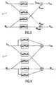
- the scheme in Fig. 2 can be replaced by the scheme in Fig. 3 .
- the left channel L O [ k ] only the parameters are necessary that determine the front/back contribution in the left input channel, which are the parameters IID L and ⁇ .
- the parameters IID R and ⁇ are necessary.
- the function g 2 can now be replaced by the function g 3 , but with an opposite sign.
- functions g 1 and g 4 are both split into two parallel function parts.
- the function g 1 is split into g 11 and g 12 .
- the function g 4 is split into g 11 and -g 12 .
- the output signals of the function part g 12 and the function g 3 are the contributions of the rear channels.
- the function part g 12 and the function g 3 need to be added with the same sign in one output, to prevent signal cancellation and with opposite sign in the different outputs.
- the function part g 12 and the function g 3 both contain a phase shift of plus or minus 90 degrees. This is to prevent cancellation of the front channel contribution (output of function part g 11 ).
- the parameter w l determines the amount of processing of L O [ k ] and w r of R O [ k ].
- L O [ k ] is not processed, and when w l is equal to 1, L O [ k ] is maximally processed.
- w r is equal to 1
- the blocks ⁇ -90 are all-pass filters that perform a 90-degree phase shift.
- the blocks G 1 and G 2 in Figure 5 are gains.
- H - 1 1 1 - w l - w r + w l ⁇ w r + w l - w r ⁇ ⁇ - 90 + G 1 ⁇ G 2 - 1 ⁇ w l ⁇ w r ⁇ ⁇ - 180 ⁇ 1 - w r - w r ⁇ ⁇ - 90 - w r ⁇ ⁇ - 90 ⁇ G 2 w l ⁇ ⁇ - 90 ⁇ G 1 1 - w l + w l ⁇ ⁇ - 90 ⁇ G 1 1 - w l + w l ⁇ ⁇ - 90 ⁇ G 1 1 - w l + w l ⁇ ⁇ - 90 ⁇ G 1 1 - w l + w l ⁇ ⁇ - 90
- the inversion can be done in the decoder without the necessity to transmit additional information, because the parameters w l and w r can be calculated from the transmitted parameters. Thus, the original stereo signal will be available again which is necessary for parametric decoding of the multi-channel mix.
- the gains G 1 and G 2 are a function of the inter-channel intensity difference (IID) between the surround channels. In that case this IID has to be transmitted to the decoder as well.
- IID inter-channel intensity difference
- f 1 ?? f 4 can be arbitrary functions.
- w r can be taken as is done in Circle Surround, but also a constant is suitable with the value 1 / 2 .
- H 1 - w l + w l ⁇ j 1 2 ⁇ 2 ⁇ w r ⁇ j - 1 2 ⁇ 2 ⁇ w l ⁇ j 1 - w r - w r ⁇ j
- det H 1 - w l - w r + 3 2 ⁇ w l ⁇ w r + j ⁇ w l - w r
- FIG. 6 shows a block diagram of an embodiment of the inverse post-processor 7.
- the inversion is done by a matrix multiplication for each frequency band:
- the functions k 1 ?? k 4 can be determined.
- the functions k 1 ?? k 4 are functions of the parameter set P , like the functions g 1 ?? g 4 . So for inversion the functions g 1 ?? g 4 and the parameter set P need to be known.
- Another application of the invention is to apply the post-processing on the stereo signal at the decoder-side only (i.e. without post-processing at the encoder side).
- the decoder can generate an enhanced stereo signal from a non-enhanced stereo signaL
- This decoder side only post-processing may be elaborated further in a situation wherein in the encoder the multichannel input signal is decoded into a single (mono) signal and associated spatial parameters.
- the mono signal may first be converted into a stereo signal (using the spatial parameters) and thereafter this stereo signal may be post-processed as described above.
- the mono signal may be decoded directly by a multichannel decoder.
Claims (14)
- Ein Verfahren zum Verarbeiten eines Stereosignals, das von einem Codierer erhalten wird, der ein N-Kanal-Audiosignal in räumliche Parameter (P) und ein Stereo-Abwärtsmisch-Signal codiert, das ein erstes und zweites Stereosignal (L0, R0) aufweist, wobei das Verfahren folgende Schritte aufweist:Addieren eines ersten Signals und eines dritten Signals, um ein erstes Ausgangssignal (L0w) zu erhalten, wobei das erste Signal (LOWL) das erste Stereosignal (L0) aufweist, modifiziert durch eine erste komplexe Funktion (g1), und wobei das dritte Signal (L0WR) das zweite Stereosignal (R0) aufweist, modifiziert durch eine dritte komplexe Funktion (g3); undAddieren eines zweiten Signals und eines vierten Signals, um ein zweites Ausgangssignal (R0w) zu erhalten, wobei das vierte Signal (R0WR) das zweite Stereosignal (R0) aufweist, modifiziert durch eine vierte komplexe Funktion (g4), und wobei das zweite Signal (ROWL) das erste Stereosignal (L0) aufweist, modifiziert durch eine zweite komplexe Funktion (g2);wobei die erste Funktion (g1) einen ersten und zweiten Funktionsteil (g11L; g12L) aufweist, wobei der Ausgang des zweiten Funktionsteils (g12L) zunimmt, wenn die räumlichen Parameter (P) anzeigen, dass ein Beitrag der Rück-Kanäle bei dem ersten Stereosignal (L0) zunimmt im Vergleich zu dem Beitrag der Front-Kanäle bei dem ersten Stereosignal (L0), und der zweite Funktionsteil (g12L) eine Phasenverschiebung aufweist, die im Wesentlichen gleich plus oder minus 90 Grad ist.
- Das Verfahren gemäß Anspruch 1, bei dem das N-Kanal-Audiosignal Front-Kanal-Signale und Rück-Kanal-Signale aufweist, und bei dem die räumlichen Parameter (P) ein Maß des relativen Beitrags der Rück-Kanäle bei dem Stereo-Abwärtsmischen (L0, R0) im Vergleich zu dem Beitrag der Front-Kanäle darin aufweisen.
- Das Verfahren gemäß Anspruch 1 oder 2, bei dem die Größe der zweiten komplexen Funktion (g2) kleiner ist als die Größe der ersten komplexen Funktion (g1) und/oder die Größe der dritten komplexen Funktion (g3) kleiner ist als die Größe der vierten komplexen Funktion (g4).
- Das Verfahren gemäß Anspruch 1, 2 oder 3, bei dem die zweite komplexe Funktion (g2) und/oder die dritte komplexe Funktion (g3) eine Phasenverschiebung aufweist, die im Wesentlichen gleich plus oder minus 90 Grad ist.
- Das Verfahren gemäß Anspruch 1, bei dem die vierte Funktion (g4) einen dritten und vierten Funktionsteil (g11R ; g12R) aufweist, wobei der Ausgang des vierten Funktionsteils (g12R) zunimmt, wenn die räumlichen Parameter (P) anzeigen, dass der Beitrag der Rück-Kanäle bei dem zweiten Stereosignal (R0) zunimmt im Vergleich zu dem Beitrag der Front-Kanäle bei dem zweiten Stereosignal (R0) und der vierte Funktionsteil (g12R) eine Phasenverschiebung aufweist, die im Wesentlichen gleich plus oder minus 90 Grad ist.
- Das Verfahren gemäß Anspruch 1, bei dem der erste Funktionsteil (g12L) ein entgegengesetztes Vorzeichen im Vergleich zu dem vierte Funktionsteil (g12R) aufweist.
- Das Verfahren gemäß Anspruch 5, bei dem die zweite Funktion (g2) ein entgegensetztes Vorzeichen im Vergleich zu der dritten Funktion (g3) aufweist.
- Das Verfahren gemäß Anspruch 6 oder 7, bei dem die zweite Funktion (g2) und der vierte Funktionsteil (g12R) dasselbe Vorzeichen haben und bei dem die dritte Funktion (g3) und der zweite Funktionsteil (g12L) dasselbe Vorzeichen haben.
- Eine Vorrichtung (5) zum Verarbeiten eines Stereosignals, das von einem Codierer erhalten wird, der ein N-Kanal-Audiosignal in räumliche Parameter (P) und ein Stereo-Abwärtsmischsignal codiert, das ein erstes und zweites Stereosignal (L0, R0) aufweist, wobei die Vorrichtung folgende Merkmale aufweist:eine erste Einrichtung zum Addieren, die konfiguriert ist, um ein erste Signal und ein drittes Signal zu addieren, um ein erstes Ausgangssignal (L0w) zu erhalten, wobei das erste Signal (L0WL) das erste Stereosignal (L0) aufweist, modifiziert durch eine erste komplexe Funktion (g1), und wobei das dritte Signal (L0WR) das zweite Stereosignal (Ro) aufweist, modifiziert durch eine dritte komplexe Funktion (g3); undeine zweite Einrichtung zum Addieren, die konfiguriert ist, um ein zweites Signal und ein viertes Signal zu addieren, um ein zweites Ausgangssignal (R0w) zu erhalten, wobei das vierte Signal (R0WR) das zweite Stereosignal (R0) aufweist, modifiziert durch eine vierte komplexe Funktion (g4), und wobei das zweite Signal (R0WL) das erste Stereosignal (L0) aufweist, modifiziert durch eine zweite komplexe Funktion (g2);wobei die erste Funktion (g1) einen ersten und zweiten Funktionsteil (g11L; g12L) aufweist, wobei die zweite Funktion derart konfiguriert ist, dass der Ausgang des zweiten Funktionsteils (g12L) zunimmt, wenn die räumlichen Parameter (P) anzeigen, dass ein Beitrag der Rück-Kanäle bei dem ersten Stereosignal (L0) zunimmt im Vergleich zu dem Beitrag der Front-Kanäle bei dem ersten Stereosignal (L0), und der zweite Funktionsteil (g12L) eine Phasenverschiebung aufweist, die im Wesentlichen gleich plus oder minus 90 Grad ist.
- Eine Codierervorrichtung, die folgende Merkmale aufweist:einen Codierer (2) zum Codieren eines N-Kanal-Audiosignals in räumliche Parameter (P) und ein Stereo-Abwärtsmisch-Signal, das ein erstes und zweites Stereosignal (L0, R0) aufweist, undeine Vorrichtung gemäß Anspruch 9 zum Verarbeiten des Stereo-Abwärtsmisch-Signals.
- Ein Verfahren zum Verarbeiten eines Stereo-Abwärtsmisch-Signals, das ein erstes und zweites Stereosignal (L0w, R0w) aufweist, wobei das Verfahren den Schritt zum Invertieren der Verarbeitungsoperation gemäß dem Verfahren von einem der Ansprüche 1 bis 8 aufweist.
- Eine Vorrichtung (7) zum Verarbeiten eines Stereo-Abwärtsmisch-Signals, das ein erstes und zweites Stereosignal (L0w, R0w) aufweist, wobei die Vorrichtung eine Einrichtung aufweist zum Invertieren der Verarbeitungsoperation gemäß dem Verfahren von einem der Ansprüche 1 bis 8.
- Eine Decodierervorrichtung, die folgende Merkmale aufweist:eine Vorrichtung (7) gemäß Anspruch 12 zum Verarbeiten eines Stereo-Abwärtsmisch-Signals, das ein erstes und zweites Stereosignal (L0w, R0w) aufweist, und einen Decodierer zum Decodieren der verarbeiteten Stereosignale (L0, R0) in ein N-Kanal-Audiosignal.
- Ein Audiosystem, das eine Codierervorrichtung gemäß Anspruch 10 und eine Decodierervorrichtung gemäß Anspruch 13 aufweist.
Priority Applications (2)
| Application Number | Priority Date | Filing Date | Title |
|---|---|---|---|
| PL10152627T PL2175671T3 (pl) | 2004-07-14 | 2005-07-07 | Sposób, urządzenie, urządzenie kodujące, urządzenie dekodujące i system audio |
| EP10152627A EP2175671B1 (de) | 2004-07-14 | 2005-07-07 | Verfahren, vorrichtung, kodierer, dekodierer und audiosystem |
Applications Claiming Priority (3)
| Application Number | Priority Date | Filing Date | Title |
|---|---|---|---|
| EP04103365 | 2004-07-14 | ||
| EP05761091A EP1769655B1 (de) | 2004-07-14 | 2005-07-07 | Verfahren, vorrichtung, kodierer, dekodierer und audiosystem |
| EP10152627A EP2175671B1 (de) | 2004-07-14 | 2005-07-07 | Verfahren, vorrichtung, kodierer, dekodierer und audiosystem |
Related Parent Applications (1)
| Application Number | Title | Priority Date | Filing Date |
|---|---|---|---|
| EP05761091.7 Division | 2005-07-07 |
Publications (3)
| Publication Number | Publication Date |
|---|---|
| EP2175671A2 EP2175671A2 (de) | 2010-04-14 |
| EP2175671A3 EP2175671A3 (de) | 2011-01-12 |
| EP2175671B1 true EP2175671B1 (de) | 2012-05-09 |
Family
ID=35044993
Family Applications (2)
| Application Number | Title | Priority Date | Filing Date |
|---|---|---|---|
| EP05761091A Active EP1769655B1 (de) | 2004-07-14 | 2005-07-07 | Verfahren, vorrichtung, kodierer, dekodierer und audiosystem |
| EP10152627A Active EP2175671B1 (de) | 2004-07-14 | 2005-07-07 | Verfahren, vorrichtung, kodierer, dekodierer und audiosystem |
Family Applications Before (1)
| Application Number | Title | Priority Date | Filing Date |
|---|---|---|---|
| EP05761091A Active EP1769655B1 (de) | 2004-07-14 | 2005-07-07 | Verfahren, vorrichtung, kodierer, dekodierer und audiosystem |
Country Status (11)
| Country | Link |
|---|---|
| US (2) | US8150042B2 (de) |
| EP (2) | EP1769655B1 (de) |
| JP (2) | JP4898673B2 (de) |
| KR (1) | KR101147187B1 (de) |
| CN (2) | CN102122508B (de) |
| AT (2) | ATE526797T1 (de) |
| ES (2) | ES2373728T3 (de) |
| HK (1) | HK1143481A1 (de) |
| PL (2) | PL2175671T3 (de) |
| TW (1) | TWI462603B (de) |
| WO (1) | WO2006008683A1 (de) |
Families Citing this family (29)
| Publication number | Priority date | Publication date | Assignee | Title |
|---|---|---|---|---|
| WO2005098826A1 (en) * | 2004-04-05 | 2005-10-20 | Koninklijke Philips Electronics N.V. | Method, device, encoder apparatus, decoder apparatus and audio system |
| EP1769491B1 (de) * | 2004-07-14 | 2009-09-30 | Koninklijke Philips Electronics N.V. | Tonkanalkonvertierung |
| PL2175671T3 (pl) * | 2004-07-14 | 2012-10-31 | Koninl Philips Electronics Nv | Sposób, urządzenie, urządzenie kodujące, urządzenie dekodujące i system audio |
| KR101346120B1 (ko) * | 2005-03-30 | 2014-01-02 | 코닌클리케 필립스 엔.브이. | 오디오 인코딩 및 디코딩 |
| JP4988717B2 (ja) | 2005-05-26 | 2012-08-01 | エルジー エレクトロニクス インコーポレイティド | オーディオ信号のデコーディング方法及び装置 |
| WO2006126844A2 (en) * | 2005-05-26 | 2006-11-30 | Lg Electronics Inc. | Method and apparatus for decoding an audio signal |
| EP1927266B1 (de) * | 2005-09-13 | 2014-05-14 | Koninklijke Philips N.V. | Audiokodierung |
| KR100803212B1 (ko) * | 2006-01-11 | 2008-02-14 | 삼성전자주식회사 | 스케일러블 채널 복호화 방법 및 장치 |
| JP4801174B2 (ja) * | 2006-01-19 | 2011-10-26 | エルジー エレクトロニクス インコーポレイティド | メディア信号の処理方法及び装置 |
| EP1982326A4 (de) * | 2006-02-07 | 2010-05-19 | Lg Electronics Inc | Vorrichtung und verfahren zum codieren/decodieren eines signals |
| JP5081838B2 (ja) | 2006-02-21 | 2012-11-28 | コーニンクレッカ フィリップス エレクトロニクス エヌ ヴィ | オーディオ符号化及び復号 |
| RU2407226C2 (ru) * | 2006-03-24 | 2010-12-20 | Долби Свидн Аб | Генерация пространственных сигналов понижающего микширования из параметрических представлений мультиканальных сигналов |
| ATE527833T1 (de) * | 2006-05-04 | 2011-10-15 | Lg Electronics Inc | Verbesserung von stereo-audiosignalen mittels neuabmischung |
| JP5134623B2 (ja) * | 2006-07-07 | 2013-01-30 | フラウンホッファー−ゲゼルシャフト ツァ フェルダールング デァ アンゲヴァンテン フォアシュンク エー.ファオ | 複数のパラメータ的に符号化された音源を合成するための概念 |
| CN101529898B (zh) | 2006-10-12 | 2014-09-17 | Lg电子株式会社 | 用于处理混合信号的装置及其方法 |
| KR100891665B1 (ko) | 2006-10-13 | 2009-04-02 | 엘지전자 주식회사 | 믹스 신호의 처리 방법 및 장치 |
| WO2008060111A1 (en) | 2006-11-15 | 2008-05-22 | Lg Electronics Inc. | A method and an apparatus for decoding an audio signal |
| KR101434198B1 (ko) * | 2006-11-17 | 2014-08-26 | 삼성전자주식회사 | 신호 복호화 방법 |
| AU2007328614B2 (en) | 2006-12-07 | 2010-08-26 | Lg Electronics Inc. | A method and an apparatus for processing an audio signal |
| EP2102855A4 (de) | 2006-12-07 | 2010-07-28 | Lg Electronics Inc | Verfahren und vorrichtung zum decodieren eines audiosignals |
| JP2010516077A (ja) | 2007-01-05 | 2010-05-13 | エルジー エレクトロニクス インコーポレイティド | オーディオ信号処理方法及び装置 |
| US8718290B2 (en) | 2010-01-26 | 2014-05-06 | Audience, Inc. | Adaptive noise reduction using level cues |
| DE102010015630B3 (de) * | 2010-04-20 | 2011-06-01 | Institut für Rundfunktechnik GmbH | Verfahren zum Erzeugen eines abwärtskompatiblen Tonformates |
| US9378754B1 (en) | 2010-04-28 | 2016-06-28 | Knowles Electronics, Llc | Adaptive spatial classifier for multi-microphone systems |
| KR101429564B1 (ko) * | 2010-09-28 | 2014-08-13 | 후아웨이 테크놀러지 컴퍼니 리미티드 | 디코딩된 다중채널 오디오 신호 또는 디코딩된 스테레오 신호를 포스트프로세싱하기 위한 장치 및 방법 |
| PL2880654T3 (pl) * | 2012-08-03 | 2018-03-30 | Fraunhofer-Gesellschaft zur Förderung der angewandten Forschung e.V. | Dekoder i sposób realizacji uogólnionej parametrycznej koncepcji kodowania przestrzennych obiektów audio dla przypadków wielokanałowego downmixu/upmixu |
| US20160269846A1 (en) * | 2013-10-02 | 2016-09-15 | Stormingswiss Gmbh | Derivation of multichannel signals from two or more basic signals |
| JP5977313B2 (ja) * | 2014-10-31 | 2016-08-24 | 住友化学株式会社 | 偏光板の製造方法 |
| GB2549532A (en) * | 2016-04-22 | 2017-10-25 | Nokia Technologies Oy | Merging audio signals with spatial metadata |
Family Cites Families (25)
| Publication number | Priority date | Publication date | Assignee | Title |
|---|---|---|---|---|
| DE4409368A1 (de) | 1994-03-18 | 1995-09-21 | Fraunhofer Ges Forschung | Verfahren zum Codieren mehrerer Audiosignale |
| US5642423A (en) | 1995-11-22 | 1997-06-24 | Sony Corporation | Digital surround sound processor |
| US5771295A (en) | 1995-12-26 | 1998-06-23 | Rocktron Corporation | 5-2-5 matrix system |
| US6198827B1 (en) | 1995-12-26 | 2001-03-06 | Rocktron Corporation | 5-2-5 Matrix system |
| US5812971A (en) | 1996-03-22 | 1998-09-22 | Lucent Technologies Inc. | Enhanced joint stereo coding method using temporal envelope shaping |
| US6697491B1 (en) * | 1996-07-19 | 2004-02-24 | Harman International Industries, Incorporated | 5-2-5 matrix encoder and decoder system |
| US6711266B1 (en) | 1997-02-07 | 2004-03-23 | Bose Corporation | Surround sound channel encoding and decoding |
| US6111958A (en) * | 1997-03-21 | 2000-08-29 | Euphonics, Incorporated | Audio spatial enhancement apparatus and methods |
| US6173061B1 (en) * | 1997-06-23 | 2001-01-09 | Harman International Industries, Inc. | Steering of monaural sources of sound using head related transfer functions |
| WO2000004744A1 (en) | 1998-07-17 | 2000-01-27 | Lucasfilm Ltd. | Multi-channel audio surround system |
| US6463410B1 (en) * | 1998-10-13 | 2002-10-08 | Victor Company Of Japan, Ltd. | Audio signal processing apparatus |
| US6539357B1 (en) | 1999-04-29 | 2003-03-25 | Agere Systems Inc. | Technique for parametric coding of a signal containing information |
| US7212872B1 (en) | 2000-05-10 | 2007-05-01 | Dts, Inc. | Discrete multichannel audio with a backward compatible mix |
| US7292901B2 (en) | 2002-06-24 | 2007-11-06 | Agere Systems Inc. | Hybrid multi-channel/cue coding/decoding of audio signals |
| US7450727B2 (en) | 2002-05-03 | 2008-11-11 | Harman International Industries, Incorporated | Multichannel downmixing device |
| JP2003333699A (ja) | 2002-05-10 | 2003-11-21 | Pioneer Electronic Corp | マトリックス・サラウンドデコード装置 |
| BRPI0305434B1 (pt) * | 2002-07-12 | 2017-06-27 | Koninklijke Philips Electronics N.V. | Methods and arrangements for encoding and decoding a multichannel audio signal, and multichannel audio coded signal |
| FI118370B (fi) * | 2002-11-22 | 2007-10-15 | Nokia Corp | Stereolaajennusverkon ulostulon ekvalisointi |
| WO2005031704A1 (en) * | 2003-09-29 | 2005-04-07 | Koninklijke Philips Electronics N.V. | Encoding audio signals |
| WO2005098826A1 (en) | 2004-04-05 | 2005-10-20 | Koninklijke Philips Electronics N.V. | Method, device, encoder apparatus, decoder apparatus and audio system |
| US8843378B2 (en) * | 2004-06-30 | 2014-09-23 | Fraunhofer-Gesellschaft Zur Foerderung Der Angewandten Forschung E.V. | Multi-channel synthesizer and method for generating a multi-channel output signal |
| US7391870B2 (en) | 2004-07-09 | 2008-06-24 | Fraunhofer-Gesellschaft Zur Foerderung Der Angewandten Forschung E V | Apparatus and method for generating a multi-channel output signal |
| PL2175671T3 (pl) | 2004-07-14 | 2012-10-31 | Koninl Philips Electronics Nv | Sposób, urządzenie, urządzenie kodujące, urządzenie dekodujące i system audio |
| US7573912B2 (en) * | 2005-02-22 | 2009-08-11 | Fraunhofer-Gesellschaft Zur Foerderung Der Angewandten Forschunng E.V. | Near-transparent or transparent multi-channel encoder/decoder scheme |
| US7751572B2 (en) * | 2005-04-15 | 2010-07-06 | Dolby International Ab | Adaptive residual audio coding |
-
2005
- 2005-07-07 PL PL10152627T patent/PL2175671T3/pl unknown
- 2005-07-07 EP EP05761091A patent/EP1769655B1/de active Active
- 2005-07-07 KR KR1020077000839A patent/KR101147187B1/ko active IP Right Grant
- 2005-07-07 US US11/571,840 patent/US8150042B2/en active Active
- 2005-07-07 PL PL05761091T patent/PL1769655T3/pl unknown
- 2005-07-07 AT AT05761091T patent/ATE526797T1/de not_active IP Right Cessation
- 2005-07-07 EP EP10152627A patent/EP2175671B1/de active Active
- 2005-07-07 JP JP2007520943A patent/JP4898673B2/ja active Active
- 2005-07-07 CN CN2010102544793A patent/CN102122508B/zh active Active
- 2005-07-07 WO PCT/IB2005/052254 patent/WO2006008683A1/en active Application Filing
- 2005-07-07 AT AT10152627T patent/ATE557552T1/de active
- 2005-07-07 ES ES05761091T patent/ES2373728T3/es active Active
- 2005-07-07 CN CN2005800238555A patent/CN1985544B/zh active Active
- 2005-07-07 ES ES10152627T patent/ES2387256T3/es active Active
- 2005-07-11 TW TW094123382A patent/TWI462603B/zh active
-
2010
- 2010-09-15 US US12/882,849 patent/US8144879B2/en active Active
- 2010-09-16 JP JP2010207979A patent/JP5485844B2/ja active Active
- 2010-10-13 HK HK10109704.6A patent/HK1143481A1/xx unknown
Also Published As
| Publication number | Publication date |
|---|---|
| JP2011039535A (ja) | 2011-02-24 |
| ATE557552T1 (de) | 2012-05-15 |
| CN102122508B (zh) | 2013-03-13 |
| EP1769655B1 (de) | 2011-09-28 |
| JP5485844B2 (ja) | 2014-05-07 |
| US20110058679A1 (en) | 2011-03-10 |
| KR20070039543A (ko) | 2007-04-12 |
| JP4898673B2 (ja) | 2012-03-21 |
| EP1769655A1 (de) | 2007-04-04 |
| CN1985544A (zh) | 2007-06-20 |
| TW200628002A (en) | 2006-08-01 |
| CN102122508A (zh) | 2011-07-13 |
| ATE526797T1 (de) | 2011-10-15 |
| JP2008537596A (ja) | 2008-09-18 |
| EP2175671A2 (de) | 2010-04-14 |
| WO2006008683A1 (en) | 2006-01-26 |
| PL1769655T3 (pl) | 2012-05-31 |
| PL2175671T3 (pl) | 2012-10-31 |
| CN1985544B (zh) | 2010-10-13 |
| US8144879B2 (en) | 2012-03-27 |
| HK1143481A1 (en) | 2010-12-31 |
| US8150042B2 (en) | 2012-04-03 |
| ES2373728T3 (es) | 2012-02-08 |
| TWI462603B (zh) | 2014-11-21 |
| ES2387256T3 (es) | 2012-09-19 |
| KR101147187B1 (ko) | 2012-07-09 |
| EP2175671A3 (de) | 2011-01-12 |
| US20070230710A1 (en) | 2007-10-04 |
Similar Documents
| Publication | Publication Date | Title |
|---|---|---|
| EP2175671B1 (de) | Verfahren, vorrichtung, kodierer, dekodierer und audiosystem | |
| US9992599B2 (en) | Method, device, encoder apparatus, decoder apparatus and audio system | |
| US10339942B2 (en) | Parametric joint-coding of audio sources | |
| KR100878367B1 (ko) | 콤팩트 보조 정보를 이용한 다중-채널 계층형 오디오 코딩 | |
| KR101158698B1 (ko) | 복수-채널 인코더, 입력 신호를 인코딩하는 방법, 저장 매체, 및 인코딩된 출력 데이터를 디코딩하도록 작동하는 디코더 | |
| AU2005204715B2 (en) | Apparatus and method for constructing a multi-channel output signal or for generating a downmix signal | |
| KR100848367B1 (ko) | 레벨 파라미터를 발생하는 장치 및 방법 그리고 멀티채널표현을 발생하는 장치 및 방법 | |
| US20080097750A1 (en) | Channel reconfiguration with side information |
Legal Events
| Date | Code | Title | Description |
|---|---|---|---|
| PUAI | Public reference made under article 153(3) epc to a published international application that has entered the european phase |
Free format text: ORIGINAL CODE: 0009012 |
|
| AC | Divisional application: reference to earlier application |
Ref document number: 1769655 Country of ref document: EP Kind code of ref document: P |
|
| AK | Designated contracting states |
Kind code of ref document: A2 Designated state(s): AT BE BG CH CY CZ DE DK EE ES FI FR GB GR HU IE IS IT LI LT LU LV MC NL PL PT RO SE SI SK TR |
|
| RIN1 | Information on inventor provided before grant (corrected) |
Inventor name: ROEDEN, KARL J. Inventor name: VAN LOON, MACHIEL W. Inventor name: BREEBART, DIRK J. Inventor name: SCHUIERS, ERIK G. P. Inventor name: PURNHAGEN, HEIKO Inventor name: HOTHO, GERARD H. |
|
| PUAL | Search report despatched |
Free format text: ORIGINAL CODE: 0009013 |
|
| RAP1 | Party data changed (applicant data changed or rights of an application transferred) |
Owner name: DOLBY INTERNATIONAL AB Owner name: KONINKLIJKE PHILIPS ELECTRONICS N.V. |
|
| REG | Reference to a national code |
Ref country code: HK Ref legal event code: DE Ref document number: 1143481 Country of ref document: HK |
|
| AK | Designated contracting states |
Kind code of ref document: A3 Designated state(s): AT BE BG CH CY CZ DE DK EE ES FI FR GB GR HU IE IS IT LI LT LU LV MC NL PL PT RO SE SI SK TR |
|
| 17P | Request for examination filed |
Effective date: 20110712 |
|
| GRAP | Despatch of communication of intention to grant a patent |
Free format text: ORIGINAL CODE: EPIDOSNIGR1 |
|
| RIC1 | Information provided on ipc code assigned before grant |
Ipc: H04S 7/00 20060101ALN20110915BHEP Ipc: G10L 19/00 20060101ALI20110915BHEP Ipc: H04S 3/02 20060101AFI20110915BHEP Ipc: H04S 1/00 20060101ALI20110915BHEP |
|
| RAP1 | Party data changed (applicant data changed or rights of an application transferred) |
Owner name: DOLBY INTERNATIONAL AB Owner name: KONINKLIJKE PHILIPS ELECTRONICS N.V. |
|
| GRAS | Grant fee paid |
Free format text: ORIGINAL CODE: EPIDOSNIGR3 |
|
| GRAA | (expected) grant |
Free format text: ORIGINAL CODE: 0009210 |
|
| AC | Divisional application: reference to earlier application |
Ref document number: 1769655 Country of ref document: EP Kind code of ref document: P |
|
| AK | Designated contracting states |
Kind code of ref document: B1 Designated state(s): AT BE BG CH CY CZ DE DK EE ES FI FR GB GR HU IE IS IT LI LT LU LV MC NL PL PT RO SE SI SK TR |
|
| REG | Reference to a national code |
Ref country code: GB Ref legal event code: FG4D |
|
| REG | Reference to a national code |
Ref country code: AT Ref legal event code: REF Ref document number: 557552 Country of ref document: AT Kind code of ref document: T Effective date: 20120515 Ref country code: CH Ref legal event code: EP |
|
| REG | Reference to a national code |
Ref country code: IE Ref legal event code: FG4D |
|
| REG | Reference to a national code |
Ref country code: DE Ref legal event code: R096 Ref document number: 602005034184 Country of ref document: DE Effective date: 20120705 |
|
| REG | Reference to a national code |
Ref country code: NL Ref legal event code: VDEP Effective date: 20120509 |
|
| REG | Reference to a national code |
Ref country code: ES Ref legal event code: FG2A Ref document number: 2387256 Country of ref document: ES Kind code of ref document: T3 Effective date: 20120919 |
|
| REG | Reference to a national code |
Ref country code: HK Ref legal event code: GR Ref document number: 1143481 Country of ref document: HK |
|
| REG | Reference to a national code |
Ref country code: LT Ref legal event code: MG4D Effective date: 20120509 |
|
| PG25 | Lapsed in a contracting state [announced via postgrant information from national office to epo] |
Ref country code: LT Free format text: LAPSE BECAUSE OF FAILURE TO SUBMIT A TRANSLATION OF THE DESCRIPTION OR TO PAY THE FEE WITHIN THE PRESCRIBED TIME-LIMIT Effective date: 20120509 Ref country code: CY Free format text: LAPSE BECAUSE OF FAILURE TO SUBMIT A TRANSLATION OF THE DESCRIPTION OR TO PAY THE FEE WITHIN THE PRESCRIBED TIME-LIMIT Effective date: 20120509 Ref country code: IS Free format text: LAPSE BECAUSE OF FAILURE TO SUBMIT A TRANSLATION OF THE DESCRIPTION OR TO PAY THE FEE WITHIN THE PRESCRIBED TIME-LIMIT Effective date: 20120909 Ref country code: SE Free format text: LAPSE BECAUSE OF FAILURE TO SUBMIT A TRANSLATION OF THE DESCRIPTION OR TO PAY THE FEE WITHIN THE PRESCRIBED TIME-LIMIT Effective date: 20120509 |
|
| REG | Reference to a national code |
Ref country code: PL Ref legal event code: T3 |
|
| REG | Reference to a national code |
Ref country code: AT Ref legal event code: MK05 Ref document number: 557552 Country of ref document: AT Kind code of ref document: T Effective date: 20120509 |
|
| PG25 | Lapsed in a contracting state [announced via postgrant information from national office to epo] |
Ref country code: LV Free format text: LAPSE BECAUSE OF FAILURE TO SUBMIT A TRANSLATION OF THE DESCRIPTION OR TO PAY THE FEE WITHIN THE PRESCRIBED TIME-LIMIT Effective date: 20120509 Ref country code: PT Free format text: LAPSE BECAUSE OF FAILURE TO SUBMIT A TRANSLATION OF THE DESCRIPTION OR TO PAY THE FEE WITHIN THE PRESCRIBED TIME-LIMIT Effective date: 20120910 Ref country code: GR Free format text: LAPSE BECAUSE OF FAILURE TO SUBMIT A TRANSLATION OF THE DESCRIPTION OR TO PAY THE FEE WITHIN THE PRESCRIBED TIME-LIMIT Effective date: 20120810 Ref country code: SI Free format text: LAPSE BECAUSE OF FAILURE TO SUBMIT A TRANSLATION OF THE DESCRIPTION OR TO PAY THE FEE WITHIN THE PRESCRIBED TIME-LIMIT Effective date: 20120509 |
|
| PG25 | Lapsed in a contracting state [announced via postgrant information from national office to epo] |
Ref country code: BE Free format text: LAPSE BECAUSE OF FAILURE TO SUBMIT A TRANSLATION OF THE DESCRIPTION OR TO PAY THE FEE WITHIN THE PRESCRIBED TIME-LIMIT Effective date: 20120509 |
|
| PG25 | Lapsed in a contracting state [announced via postgrant information from national office to epo] |
Ref country code: SK Free format text: LAPSE BECAUSE OF FAILURE TO SUBMIT A TRANSLATION OF THE DESCRIPTION OR TO PAY THE FEE WITHIN THE PRESCRIBED TIME-LIMIT Effective date: 20120509 Ref country code: NL Free format text: LAPSE BECAUSE OF FAILURE TO SUBMIT A TRANSLATION OF THE DESCRIPTION OR TO PAY THE FEE WITHIN THE PRESCRIBED TIME-LIMIT Effective date: 20120509 Ref country code: DK Free format text: LAPSE BECAUSE OF FAILURE TO SUBMIT A TRANSLATION OF THE DESCRIPTION OR TO PAY THE FEE WITHIN THE PRESCRIBED TIME-LIMIT Effective date: 20120509 Ref country code: AT Free format text: LAPSE BECAUSE OF FAILURE TO SUBMIT A TRANSLATION OF THE DESCRIPTION OR TO PAY THE FEE WITHIN THE PRESCRIBED TIME-LIMIT Effective date: 20120509 Ref country code: EE Free format text: LAPSE BECAUSE OF FAILURE TO SUBMIT A TRANSLATION OF THE DESCRIPTION OR TO PAY THE FEE WITHIN THE PRESCRIBED TIME-LIMIT Effective date: 20120509 Ref country code: RO Free format text: LAPSE BECAUSE OF FAILURE TO SUBMIT A TRANSLATION OF THE DESCRIPTION OR TO PAY THE FEE WITHIN THE PRESCRIBED TIME-LIMIT Effective date: 20120509 Ref country code: CZ Free format text: LAPSE BECAUSE OF FAILURE TO SUBMIT A TRANSLATION OF THE DESCRIPTION OR TO PAY THE FEE WITHIN THE PRESCRIBED TIME-LIMIT Effective date: 20120509 |
|
| PGFP | Annual fee paid to national office [announced via postgrant information from national office to epo] |
Ref country code: NL Payment date: 20120727 Year of fee payment: 8 |
|
| PG25 | Lapsed in a contracting state [announced via postgrant information from national office to epo] |
Ref country code: MC Free format text: LAPSE BECAUSE OF NON-PAYMENT OF DUE FEES Effective date: 20120731 |
|
| REG | Reference to a national code |
Ref country code: CH Ref legal event code: PL |
|
| PLBE | No opposition filed within time limit |
Free format text: ORIGINAL CODE: 0009261 |
|
| STAA | Information on the status of an ep patent application or granted ep patent |
Free format text: STATUS: NO OPPOSITION FILED WITHIN TIME LIMIT |
|
| 26N | No opposition filed |
Effective date: 20130212 |
|
| PG25 | Lapsed in a contracting state [announced via postgrant information from national office to epo] |
Ref country code: CH Free format text: LAPSE BECAUSE OF NON-PAYMENT OF DUE FEES Effective date: 20120731 Ref country code: LI Free format text: LAPSE BECAUSE OF NON-PAYMENT OF DUE FEES Effective date: 20120731 |
|
| REG | Reference to a national code |
Ref country code: IE Ref legal event code: MM4A |
|
| REG | Reference to a national code |
Ref country code: DE Ref legal event code: R097 Ref document number: 602005034184 Country of ref document: DE Effective date: 20130212 |
|
| PG25 | Lapsed in a contracting state [announced via postgrant information from national office to epo] |
Ref country code: IE Free format text: LAPSE BECAUSE OF NON-PAYMENT OF DUE FEES Effective date: 20120707 Ref country code: BG Free format text: LAPSE BECAUSE OF FAILURE TO SUBMIT A TRANSLATION OF THE DESCRIPTION OR TO PAY THE FEE WITHIN THE PRESCRIBED TIME-LIMIT Effective date: 20120809 |
|
| REG | Reference to a national code |
Ref country code: ES Ref legal event code: PC2A Owner name: KONINKLIJKE PHILIPS N.V. Effective date: 20140224 |
|
| REG | Reference to a national code |
Ref country code: DE Ref legal event code: R081 Ref document number: 602005034184 Country of ref document: DE Owner name: KONINKLIJKE PHILIPS N.V., NL Free format text: FORMER OWNER: DOLBY INTERNATIONAL AB, KONINKLIJKE PHILIPS ELECTRONICS, , NL Effective date: 20140320 Ref country code: DE Ref legal event code: R081 Ref document number: 602005034184 Country of ref document: DE Owner name: DOLBY INTERNATIONAL AB, NL Free format text: FORMER OWNER: DOLBY INTERNATIONAL AB, KONINKLIJKE PHILIPS ELECTRONICS, , NL Effective date: 20140320 Ref country code: DE Ref legal event code: R082 Ref document number: 602005034184 Country of ref document: DE Representative=s name: SCHOPPE, ZIMMERMANN, STOECKELER, ZINKLER, SCHE, DE Effective date: 20140320 Ref country code: DE Ref legal event code: R081 Ref document number: 602005034184 Country of ref document: DE Owner name: KONINKLIJKE PHILIPS N.V., NL Free format text: FORMER OWNERS: DOLBY INTERNATIONAL AB, AMSTERDAM, NL; KONINKLIJKE PHILIPS ELECTRONICS N.V., EINDHOVEN, NL Effective date: 20140320 Ref country code: DE Ref legal event code: R081 Ref document number: 602005034184 Country of ref document: DE Owner name: DOLBY INTERNATIONAL AB, NL Free format text: FORMER OWNERS: DOLBY INTERNATIONAL AB, AMSTERDAM, NL; KONINKLIJKE PHILIPS ELECTRONICS N.V., EINDHOVEN, NL Effective date: 20140320 Ref country code: DE Ref legal event code: R082 Ref document number: 602005034184 Country of ref document: DE Representative=s name: SCHOPPE, ZIMMERMANN, STOECKELER, ZINKLER & PAR, DE Effective date: 20140320 |
|
| PG25 | Lapsed in a contracting state [announced via postgrant information from national office to epo] |
Ref country code: LU Free format text: LAPSE BECAUSE OF NON-PAYMENT OF DUE FEES Effective date: 20120707 |
|
| PG25 | Lapsed in a contracting state [announced via postgrant information from national office to epo] |
Ref country code: HU Free format text: LAPSE BECAUSE OF FAILURE TO SUBMIT A TRANSLATION OF THE DESCRIPTION OR TO PAY THE FEE WITHIN THE PRESCRIBED TIME-LIMIT Effective date: 20050707 |
|
| REG | Reference to a national code |
Ref country code: FR Ref legal event code: CA Effective date: 20140806 Ref country code: FR Ref legal event code: CD Owner name: DOLBY INTERNATIONAL AB, NL Effective date: 20140806 Ref country code: FR Ref legal event code: CD Owner name: KONINKLIJKE PHILIPS ELECTRONICS N Effective date: 20140806 |
|
| REG | Reference to a national code |
Ref country code: FR Ref legal event code: PLFP Year of fee payment: 12 |
|
| REG | Reference to a national code |
Ref country code: FR Ref legal event code: PLFP Year of fee payment: 13 |
|
| REG | Reference to a national code |
Ref country code: FR Ref legal event code: PLFP Year of fee payment: 14 |
|
| REG | Reference to a national code |
Ref country code: FR Ref legal event code: PLFP Year of fee payment: 18 |
|
| REG | Reference to a national code |
Ref country code: DE Ref legal event code: R081 Ref document number: 602005034184 Country of ref document: DE Owner name: DOLBY INTERNATIONAL AB, IE Free format text: FORMER OWNERS: DOLBY INTERNATIONAL AB, AMSTERDAM, NL; KONINKLIJKE PHILIPS N.V., EINDHOVEN, NL Ref country code: DE Ref legal event code: R081 Ref document number: 602005034184 Country of ref document: DE Owner name: KONINKLIJKE PHILIPS N.V., NL Free format text: FORMER OWNERS: DOLBY INTERNATIONAL AB, AMSTERDAM, NL; KONINKLIJKE PHILIPS N.V., EINDHOVEN, NL Ref country code: DE Ref legal event code: R081 Ref document number: 602005034184 Country of ref document: DE Owner name: DOLBY INTERNATIONAL AB, NL Free format text: FORMER OWNERS: DOLBY INTERNATIONAL AB, AMSTERDAM, NL; KONINKLIJKE PHILIPS N.V., EINDHOVEN, NL |
|
| REG | Reference to a national code |
Ref country code: DE Ref legal event code: R081 Ref document number: 602005034184 Country of ref document: DE Owner name: KONINKLIJKE PHILIPS N.V., NL Free format text: FORMER OWNERS: DOLBY INTERNATIONAL AB, DP AMSTERDAM, NL; KONINKLIJKE PHILIPS N.V., EINDHOVEN, NL Ref country code: DE Ref legal event code: R081 Ref document number: 602005034184 Country of ref document: DE Owner name: DOLBY INTERNATIONAL AB, IE Free format text: FORMER OWNERS: DOLBY INTERNATIONAL AB, DP AMSTERDAM, NL; KONINKLIJKE PHILIPS N.V., EINDHOVEN, NL |
|
| P01 | Opt-out of the competence of the unified patent court (upc) registered |
Effective date: 20230528 |
|
| P02 | Opt-out of the competence of the unified patent court (upc) changed |
Effective date: 20230528 |
|
| PGFP | Annual fee paid to national office [announced via postgrant information from national office to epo] |
Ref country code: PL Payment date: 20230628 Year of fee payment: 19 |
|
| PGFP | Annual fee paid to national office [announced via postgrant information from national office to epo] |
Ref country code: TR Payment date: 20230704 Year of fee payment: 19 Ref country code: IT Payment date: 20230727 Year of fee payment: 19 Ref country code: GB Payment date: 20230713 Year of fee payment: 19 Ref country code: FI Payment date: 20230713 Year of fee payment: 19 Ref country code: ES Payment date: 20230801 Year of fee payment: 19 |
|
| PGFP | Annual fee paid to national office [announced via postgrant information from national office to epo] |
Ref country code: FR Payment date: 20230713 Year of fee payment: 19 Ref country code: DE Payment date: 20230717 Year of fee payment: 19 |