BACKGROUND OF THE INVENTION
1. Field of the Invention:
-
The present invention generally relates to a mechanical-to-electrical energy conversion technology and, more particularly, to a swinging apparatus and an energy harvester using the swinging apparatus wherein the swinging frequency can be adjusted automatically and mechanical energy can be converted to electrical energy.
2. Description of the Prior Art:
-
The tires play an important role when the performance and safety of a vehicle is concerned. If the tire condition can be monitored, danger due to tire puncture can be prevented, adaptability of roads can be improved, gasoline consumption can be reduced, lifetime of the tires can be lengthened, and the cost of a vehicle can be reduced. To effectively monitor the tire condition, the tire pressure monitoring system (TPMS) has been adopted by the vehicle industry. According to National Thruway and Highway Traffic Safety Administration (NTHTSA), since 2007, all the cars to be sold in the U.S. have to be equipped with tire pressure monitoring systems, which will soon be the next big thing in the car electronic applications.
-
The TPMS is used for real-time automatic tire pressure monitoring when the car is moving so as to issue an alarm of a flat or low-pressure tire to insure driving safety. The TPMS is an alarm system for protecting the lives of the driver and the passengers. Statistically, there will be 29,000,000 cars demanded in Europe and 18,000,000 units demanded in Europe by the year of 2010, which leads to a total of 192,000,000 TPMS's. The power consumption of a TPMS is 70 µW as powered by Li batteries. Even though Li batteries provide sufficient energy for monitoring the tire pressure, Li batteries are harmful to the environment. Environment-friendly products are more popular in U.S. and some developed countries in Europe. According to Kyoto Protocol and ROHS, people are encouraged to manufacture environment-friendly products.
-
Therefore, there have been a number of various energy harvesters to replace the batteries. For example, in
U.S. Pat. Pub. No. 2005/0151375 , an energy harvester is disclosed to convert mechanical energy to electrical energy to be used in the pressure gauge. Magnetic movement (Faraday's Law) is used in the prior art to convert the kinetic energy into electrical energy. However, power generation by magnetic movement is limited to the moving velocity of the magnetic.
-
Furthermore, in
U.S. Pat. No. 6,407,484 , a piezoelectric energy harvester is disclosed to convert rotational energy to electrical energy. The centrifugal force of the rotational element drives the metallic sheet to expand or contract the piezoelectric material to convert strain energy to electrical energy. Moreover, in
U.S. Pat. Pub. No. 2004/0075363 , piezoelectric cantilever beams are used to convert vibration energy to electrical energy. Piezoelectric cantilever beams with various lengths are used to harvest vibration energy at different frequencies. Moreover,
U.S. Pat. No. 7,116,036 and
U.S. Pat. No. 7,256,505 also disclose an energy harvester that replaces conventional batteries.
SUMMARY OF THE INVENTION
-
The present invention provides a swinging apparatus comprising an energy provider and a swinging mechanism disposed thereon. By means of adjusting the distance between the swinging mechanism and the energy provider and the ratio of the swinging mechanism to a characteristic value, the swinging frequency of the swinging mechanism may be adjusted automatically with the variation of the motion frequency of the energy provider.
-
The present invention provides a swinging apparatus, wherein a weight loading portion is disposed on a swinging mechanism capable of swinging according to the variation of the driving energy frequency so that the swinging mechanism causes resonance during swinging and the swinging frequency varies with the variation of the rotational frequency of the driving rotational velocity to harvest the low-frequency energy.
-
The present invention provides an energy harvester, wherein the natural frequency automatically varies with the variation of the driving energy frequency so that that the swinging mechanism with a weight loading portion is resonating at any time. Therefore, large displacement and large velocity are caused under any driving rotational velocity to improve the mechanical-to-electrical energy conversion efficiency.
-
In one embodiment, the present invention provides a swinging apparatus, comprising: an energy provider, being capable of performing a rotational movement with respect to a rotational axis; and a swinging mechanism, being disposed on the energy provider and being a specific distance away from the rotational axis, wherein a ratio of the specific distance to a characteristic value is in a range between 4 and 0.25, and the characteristic value is a ratio of the rotational inertia of the swinging mechanism to an equivalent constant of the swinging mechanism.
-
In another embodiment, the present invention further provides an energy harvester, comprising: an energy provider, being capable of performing a rotational movement with respect to a rotational axis; a magnetic swinging mechanism, being disposed on the energy provider and being a specific distance away from the rotational axis; and an induction coil portion, being disposed corresponding to the magnetic swinging mechanism to generate an induced current when the magnetic swinging mechanism is swinging.
BRIEF DESCRIPTION OF THE DRAWINGS
-
The objects, spirits and advantages of various embodiments of the present invention will be readily understood by the accompanying drawings and detailed descriptions, wherein:
- FIG 1A and FIG 1B are schematic diagrams of a swinging apparatus according to one embodiment of the present invention;
- FIG. 2A to FIG. 2C are schematic diagrams of a swinging apparatus comprising a single object according to one embodiment of the present invention;
- FIG. 3A and FIG 3B are schematic diagrams of an energy harvester according to one embodiment of the present invention;
- FIG. 4 is a schematic diagram of a swinging apparatus according to another embodiment of the present invention;
- FIG. 5A and FIG. 5B are schematic diagrams showing the operations of a swinging apparatus according to another embodiment of the present invention;
- FIG 6 is a schematic diagram showing the swing of a swinging mechanism when an energy provider is rotating in the present invention;
- FIG. 7A to FIG 7F are schematic diagrams of a swinging mechanism according to other embodiments of the present invention;
- FIG 8A is a schematic diagram of an energy harvester according to another embodiment of the present invention;
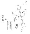
- FIG. 8B is a schematic diagram of an energy harvester according to still another embodiment of the present invention; and
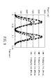
- FIG 9 is a graph showing the power generated by the energy harvester of the present invention.
DETAILED DESCRIPTION OF THE PREFERRED EMBODIMENT
-
The present invention can be exemplified but not limited by the embodiments as described hereinafter.
-
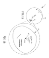
Please refer to
FIG. 1A and FIG. 1B, which are schematic diagrams of a swinging apparatus according to one embodiment of the present invention. In the present embodiment, the
swinging apparatus 1 comprises a
swinging mechanism 11, which is coupled to an
energy provider 10. The
energy provider 10 is capable of rotating with an angular velocity of ω. When the
energy provider 10 is rotating, the center O is stationary (by simply rotating) or making a translational movement (by rolling). Since the center of the swinging
mechanism 11 is a specific distance R from the center O of the
energy provider 10, the swinging
mechanism 11 experiences a centrifugal acceleration
a, expressed as Equation (1):
-
When the
energy provider 10 is rotating, the gravity the swinging
mechanism 11 experiences varies with the change of its position to further drive the swinging
mechanism 11 to swing with respect to its
fulcrum 110 as a center. The volume of the swinging apparatus is V and the density of mass is ρ, a function of its coordinate (x,y,z). In other words, the swinging
mechanism 11 comprises materials of different densities. Assuming the swinging angle is θ, the motion equation of the swinging mechanism according to the vibration theory is expressed as Equation (2):
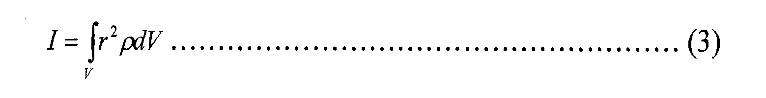
wherein t is time, g is gravity acceleration. Therefore, the rotational inertia I of the swinging
mechanism 11 is expressed as Equation (3):
-
Moreover, the swinging
mechanism 11 further comprises an equivalent elastic constant K, expressed as Equation (4), a relation of the angular velocity ω, the specific distance R and an equivalent constant
-
Therefore, according to Equations (3) and (4), the swinging natural frequency ω
n can be obtained as Equation (5):
wherein L* is a characteristic value, which is the ratio of the rotational inertia I to the equivalent constant, expressed as Equation (6):
-
According to the resonance principle in the vibration theory, if the angular velocity ω (rotational frequency) of the
energy provider 10 approaches the natural frequency of the swinging
mechanism 11, resonance happens to the swinging
mechanism 11. In other words, as Equation (7) holds, resonance takes place:
-
Therefore, as the parameters such as the size, the density and the shape of the swinging
mechanism 11 are properly selected, ω
n ≅ ω. In other words, with the parameters such as the size, the density and the shape of the swinging
mechanism 11 being properly selected, the swinging
mechanism 11 resonates with the movement of the
energy provider 10. In the present embodiment, the ratio of the specific distance R to the characteristic value
L* is in a range between 4 and 0.25, In other words, the root value of the ratio is in a range between 2 and 0.5, expressed as Equation (8):
-
From
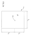
FIG. 1A and FIG. 1B, the swinging mechanism may be implemented in two modes. In the first mode, the swinging mechanism is a single object or a plurality of objects (with different density distributions) interconnected. In the second mode, the swinging mechanism comprises a plurality of objects and shafts. First, please refer to
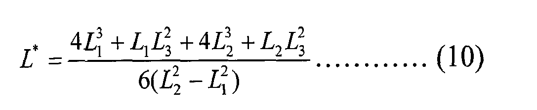
FIG 2A, which is a schematic diagram of a swinging apparatus comprising a single object according to one embodiment of the present invention. In the present embodiment, the swinging
mechanism 11a is disposed on an energy provider (as shown in
FIG. 1A) and is a rectangular plate with a density of mass of p and a swinging
fulcrum 110 as a fulcrum. As previously stated, the motion equation of the swinging mechanism in
FIG. 2A can be obtained as Equations (9) and (10):
-
According to Equations (5), (7) and (8), when the energy provider is rotating, the centrifugal force enables the natural frequency ω n of the swinging mechanism 11a to be automatically adjusted with the variation of ω. In other words, when the rotational velocity ω of the energy provider increases, the natural frequency ω n of the swinging mechanism also increases. On the contrary, when the rotational velocity ω of the tire slows down, the natural frequency ω n of the swinging mechanism decreases.
-
As shown in
FIG 2B, the present embodiment is basically similar to the structure in
FIG. 2A. In other words, the
swinging mechanism 11b comprises a single object. However, the single object on the
swinging mechanism 11b is composed of two
rectangular plates 111 and 112, each with a density of mass of ρ
1 and ρ
2, respectively. The
swinging mechanism 11b swings with respect to a
fulcrum 110b. Similarly, as previously stated, the motion equation of the
swinging mechanism 11b in
FIG. 2B can be obtained as Equations (11) and (12):
-
According to Equations (5), (7) and (8), when the energy provider is rotating, the centrifugal force enables the natural frequency ω n of the swinging mechanism 11b to be automatically adjusted with the variation of ω. In other words, when the rotational velocity ω of the energy provider increases, the natural frequency ω n of the swinging mechanism also increases. On the contrary, when the rotational velocity ω of the tire slows down, the natural frequency ω n of the swinging mechanism decreases.
-
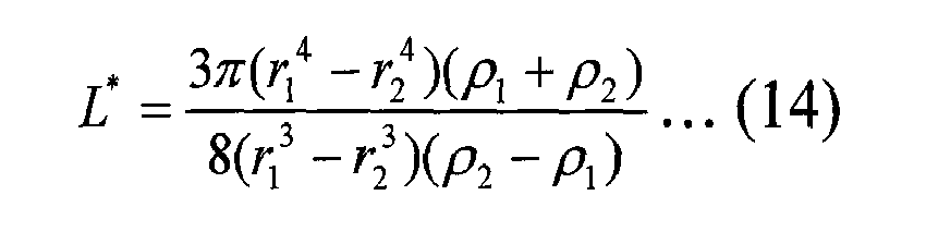
As shown in
FIG 2C, the swinging
mechanism 11c is composed of two
semi-rings 113 and 114, each with a density of mass of ρ
1 and ρ
2, respectively. The swinging
mechanism 11c swings with respect to a
fulcrum 110c. Similarly, as previously stated, the motion equation of the
swinging mechanism 11c in
FIG. 2C can be obtained as Equations (13) and (14):
-
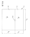
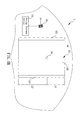
FIG. 3A and FIG. 3B are schematic diagrams of an energy harvester according to one embodiment of the present invention. In FIG. 3A and FIG. 3B, the energy harvester in the first mode is used. In other words, the magnetic effect due to the swing motion contributes to power generation. In FIG. 3A, the energy harvester 4 comprises an energy provider 40, a magnetic swinging mechanism 41, an induction coil portion 42, an energy storage device 43 and a sensor 44. The energy provider 40 is an object that is capable of rotating or rolling (exemplified by, but not limited to, a tire) with a rotational angular velocity. The magnetic swinging mechanism 41 basically is similar to the swinging mechanism 11c in FIG. 2C. The magnetic swinging mechanism 41 comprises a connecting portion 410 and at least a magnetic object. In the present embodiment, a pair of magnetic objects 412 and 413 are provided. The connecting portion 410 comprises a fulcrum 411 on one end so that the magnetic swinging mechanism 41 may swing with respect to the fulcrum 411. The operating mechanism of the magnetic swinging mechanism 41 is as stated above and is not repeated herein. The magnetic objects 412 and 413 comprise magnetic materials to exhibit a magnetic field. In the present embodiment, the magnetic objects 412 and 413 further comprise a gap D therebetween. The induction coil portion 42 comprises a pipe 420 with a curvature. On the outer wall of the pipe 420, there is an induction coil 421. On both ends of the pipe 420, parts of the magnetic objects 412 and 413 are enclosed therein. The energy storage device 43 is coupled to the induction coil 421. In the present embodiment, the energy storage device 43 is implemented by a battery or other energy storage devices. Moreover, the energy storage device 43 is further coupled to a sensor 44, which can be implemented by a pressure sensor, a temperature sensor or other sensors. When the energy provider 40 is rotating or rolling, the magnetic swinging mechanism 41 resonates to swing in the pipe. During the swinging of the magnetic swinging mechanism 41, an induced current is induced in the induction coil 421 on the outer wall of the pipe 420 to further store the induced electrical energy in the energy storage device 43 to be supplied to the sensor 44. In the present embodiment, the connecting portion 410 is analogous to the object 113 in FIG. 2C, and the pair of magnetic objects 412 and 413 are analogous to the object 114.
-
As shown in FIG. 3B, in the present embodiment, the energy harvester 5 as formed in FIG 2A is used. In the present embodiment, the energy harvester comprises an energy provider 50, a magnetic swinging mechanism 52, an induction coil 53 and an energy storage device 54. The energy provider 50 is as previously stated and is not repeated herein. The magnetic swinging mechanism 52 swings with respect to a fulcrum 51. The magnetic swinging mechanism 52 comprises an object 520, which is coupled to magnetic objects 521 on both sides. Certainly, the object 520 and the magnetic objects 521 can be formed as a single object with magnetism. The induction coil 53 and the energy storage device 54 are as previously stated and are not repeated herein. Certainly, the energy storage device 54 can be coupled to the sensor, which is as previously stated and is not repeated herein.
-
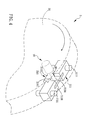
The second mode will be described hereinafter. Please refer to FIG. 4, which is a schematic diagram of a swinging apparatus according to another embodiment of the present invention. In the present embodiment, the swinging apparatus 2 comprises an energy provider 20 and a swinging mechanism 21 comprising a swinging portion 210 and a weight loading portion 211. The energy provider 20 is capable of providing the swinging mechanism 21 with energy. The energy provider 20 is a rotator or a roller, but it is not limited thereto. In other words, the energy provider 20 is capable of changing the gravity of the swinging mechanism experiences by a rotational movement. The roller is capable of rotating and moving translationally. In the present embodiment, the energy provider 20 is the rim of a tire. The rim is rotating or rolling to change the gravity experienced by the swinging portion so that the swinging portion 210 in the swinging mechanism 21 swings. The swinging portion 210 disposed on the energy provider 20 swings with respect to a fulcrum 2100. The fulcrum 2100 is coupled to the energy provider 20 via a shaft 90.
-
The swinging portion 210 comprises a shaft 2101 and an object 2102. The shaft 2101 is coupled to the fulcrum 2100 on one end, and the object 2102 is coupled to the other end of the shaft 2101. The object 2102 exhibits magnetism or is an object formed of metallic and magnetic materials. The weight loading portion 211 is coupled to the swinging portion 210 to enable the swinging frequency of the swinging portion 210 to vary with the variation of the frequency of the energy supplied by the energy provider 20. In the present embodiment, the weight loading portion 211 comprises a shaft 2110 and a pair of objects 2111. The center of the shaft 2110 is coupled to the fulcrum 2100, and the pair of objects 2111 is coupled to both ends of the shaft 2110, respectively. In the present embodiment, the pair of objects 2111 exhibits magnetism or are objects formed of metallic and magnetic materials.
-
Please refer to
FIG 5A and FIG 5B for schematic diagrams showing the operations of a swinging apparatus according to another embodiment of the present invention. In
FIG 5A, a swinging
apparatus 2 is shown comprising a swinging
mechanism 21 disposed on the
energy provider 20a. In the present embodiment, the
energy provider 20a is a rim.
Label 22 denotes the tire attached onto the
rim 20a. For clarity, the swinging portion and the weight loading portion in
FIG. 5B are reduced from the swinging portion and the weight loading portion in
FIG 4, wherein identical labels denote identical elements. According to the vibration theory, the motion equation of the system in
FIG. 5B is expressed as Equation (15):
wherein m
1 and m
2 represent the
objects 2102 and 2111 in
FIG. 4, respectively, L
1 represents the length of the
shaft 2101, L
2 represents the length of the
shaft 2110, and θ represents the swinging angle of the swinging
mechanism 21. During the rotation of the
rim 20a, the centripetal force generated by the swinging
mechanism 21 is expressed as Equation (16):
wherein
a is the centripetal acceleration, r is the radius of the rim, R is the total radius of the
rim 20a and the
tire 22, and
V is the velocity of the center of mass of the tire when the wheel (including the
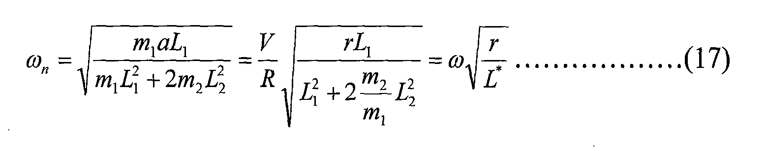
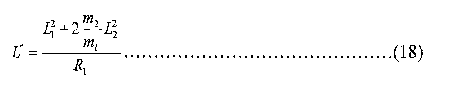
rim 20a and the tire 22) is rolling. Therefore, according to Equation (15) and Equation (16), the natural frequency ω
n of the swinging
mechanism 21 is expressed as Equation (17):
L* is expressed as Equation (18):
-
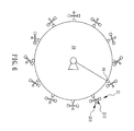
In Equation (17), ω n represents the natural frequency of the swinging mechanism 21, and ω represents the angular velocity or the rotational frequency when the energy provider 20 is rolling or rotating. From Equations (17) and (18), the relation between m1, m2, L1 and L2 is obtained. Since the present invention comprises a weight loading portion 211, when the tire is rotating, the centrifugal force enables the natural frequency ω n of the swinging mechanism 21 to vary with the variation of ω to be automatically adjusted. In other words, the natural frequency ω n of the swinging mechanism also increases when the rotational velocity ω of the tire increases. On the contrary, when the rotational velocity ω of the tire slows down, the natural frequency ω n of the swinging mechanism also decreases. Please refer to FIG 6, which is a schematic diagram showing the swing of a swinging mechanism when an energy provider is rotating in the present invention. More particularly, FIG. 6 shows the swinging of a swinging mechanism 21 comprising a swinging portion 210 and a weight loading portion 211 disposed on the position 91 on the energy provider 20 when the energy provider 20 rotates counterclockwise. Other positions excluding the position 91 on the swinging mechanism correspond to different swinging states when the energy provider 20 is rotating or rolling.
-
Moreover, according to Equation (17) and Equation (18), as m1, m2, L1 and L2 are properly selected, ω n ≅ ω. In other words, with the m1, m2, L1 and L2 being properly selected, the swinging mechanism 21 is resonating with the rotational frequency when the swinging mechanism 21 is rotating with the wheel. Therefore, the maximum amplitude of the rotational frequency of the swinging mechanism 21 is achieved due to resonance so as to harvest the work accomplished on the swinging mechanism experiencing the gravity when the wheel is rolling. For example, considering the radius of the wheel (including the rim 20a and the tire 22) is 0.3 m and the radius of the rim 22a is 0.2 m, if L1=4mm, L2=14mm, m1=2.5g and m2=5g, the natural frequency of the swinging mechanism 21 is equal to the rotational frequency of the wheel whatever the car speed is. In other words, the swinging mechanism is resonating at any time so as to achieve the maximum swinging amplitude.
-
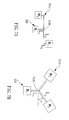
Please refer to
FIG 7A to FIG. 7F for the schematic diagrams of a swinging mechanism according to other embodiments of the present invention. In the embodiments in
FIG. 7A to FIG. 7D, the swinging
portion 210 is similar to the swinging portion in
FIG 4 except that the
weight loading portion 210 in
FIG. 7A to FIG. 7D is modified based on the spirits as previously stated. In
FIG 7A, the
weight loading portion 211 a comprises a plurality of shafts, namely the shaft L
2 and the shaft L
3. Taking the shaft on the right side of the
fulcrum 2100 for example, the shaft L
2 is coupled to the
fulcrum 2100 on one end and is coupled to the shaft L
3 on the other end. The other end of the shaft L
3 is coupled to the object m
2. In
FIG. 7A, the motion equation of the swinging mechanism is expressed as Equations (19) and (20), wherein
a is the centrifugal force, and θ is the swinging angle;
-
As shown in
FIG. 7B, the
weight loading portion 211b in the present embodiment comprises a pair of shafts coupled to the
fulcrum 2100 on one end, and an angle φ is between the two shafts and the horizontal line. The motion equation is expressed as Equations (21) and (22):
-
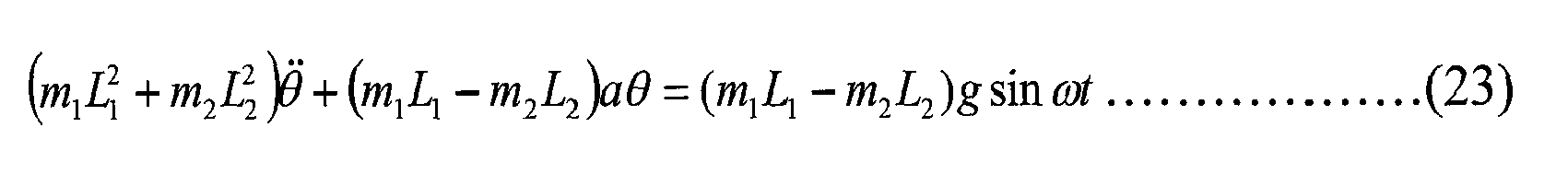
Furthermore, as shown in
FIG. 7C, in the present embodiment, the
weight loading portion 211c comprises a shaft L
2 coupled to the
fulcrum 2100. The motion equation is expressed as Equations (23) and (24):
-
As shown in
FIG 7D, in the present embodiment, the
weight loading portion 211d is similar to the
weight loading portion 211c in
FIG. 4 except that the
fulcrum 2100 coupled to the shafts is not located at the center. Therefore, the distances from the objects m
2 and m
3 to the fulcrum are L
2 and L
3, respectively. In the swinging mechanism of the present embodiment, the motion equation is expressed as Equations (25), (26) and Equation (27):
-
As shown in
FIG. 7E, in the present embodiment, the swinging
portion 210a and the
weight loading portion 211e are structured as a cross shape. The swinging
portion 210a comprises a shaft L
1. The shaft L
1 is coupled to an object m
1 on one end, and is coupled to a
fulcrum 2100 on the other end. The
weight loading portion 211e comprises a shaft L
2 and two shafts L
3. These three shafts L
2 and L
3 are connected to the
fulcrum 2100 on one end, and connected to objects m
2 and m
3, respectively, on the other end. The motion equation in
FIG. 7E is expressed as Equations (28) and (29):
-
In
FIG. 7F, unlike the previous embodiment, the
weight loading portion 211f is not coupled to the
fulcrum 2100. The shafts L
2 of the
weight loading portion 211f are both coupled to the object m
1 of the swinging
portion 210. The motion equation of the swinging mechanism in
FIG 7F is expressed as Equations (30) and (31):
-
From the motion equations in the previous embodiments, the relation between the natural frequency of ω n of the swinging mechanism and the motion frequency of ω of the energy provider can be acquired. Therefore, the design of the swinging mechanisms in FIG. 7A to FIG. 7F enables the natural frequency ω n to vary with the frequency ω of the power from the energy provider. As the mass of the object and the shaft length are properly selected, ωn ≅ ω.
-
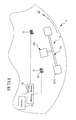
As shown in FIG. 8A, which is a schematic diagram of an energy harvester according to another embodiment of the present invention, the energy harvester 3 comprises an energy provider 30, a magnetic swinging mechanism 31 and a pair of induction coils 33. The energy provider 30 is structured as the energy provider 20 in the previous embodiment in FIG. 4, and thus a description is not repeated herein. The magnetic swinging mechanism 31 comprises a swinging portion 310 and a weight loading portion 311. In the present embodiment, the swinging portion 310 and the weight loading portion 311 are structured as those in FIG. 4 except that the objects 3110 on both ends of the weight loading portion 311 are magnetic objects, which may provide a magnetic field. The pair of induction coils 33 is disposed respectively on one side of the magnetic objects 3110. When the energy provider 30 is rotating, the magnetic swinging mechanism 31 resonates according to the description in FIG. 4. Therefore, an induced current is induced in the pair of the induction coils 33 during the swinging of the magnetic objects 3110 so as to store induced energy in the energy storage device 34 coupled to the induction coils 33. Please refer to FIG. 9, which is a graph showing the power generated by the energy harvester of the present invention. In FIG. 9, it is found that the swinging mechanism disposed on the rim may generate milli-watts of power when the car is moving at a speed of 50 Km/h.
-
Please refer to FIG. 8B, which is a schematic diagram of an energy harvester according to still another embodiment of the present invention. The present embodiment is similar to the embodiment in FIG. 8A except that the object 3100 of the swinging portion 310 in the present embodiment is a magnetic object. Therefore, the induction coil 33 is disposed on a position corresponding to the magnetic object 3100 of the swinging portion 310. Referring to FIG 8A, the energy storage device 34 is further coupled to a sensor 35. In the present embodiment, the sensor 35 is a pressure sensor for detecting whether the tire pressure is normal. Certainly, the magnetic swinging mechanism 31 can be replaced according to FIG 7A to FIG. 7F.
-
Accordingly, the present invention discloses a swinging apparatus and an energy harvester using the swinging apparatus wherein the swinging frequency can be adjusted automatically and mechanical energy can be converted to electrical energy. Therefore, the present invention is useful, novel and non-obvious.
-
Although this invention has been disclosed and illustrated with reference to particular embodiments, the principles involved are susceptible for use in numerous other embodiments that will be apparent to persons skilled in the art. This invention is, therefore, to be limited only as indicated by the scope of the appended claims.