EP2175537A2 - Differential power detection - Google Patents
Differential power detection Download PDFInfo
- Publication number
- EP2175537A2 EP2175537A2 EP09251411A EP09251411A EP2175537A2 EP 2175537 A2 EP2175537 A2 EP 2175537A2 EP 09251411 A EP09251411 A EP 09251411A EP 09251411 A EP09251411 A EP 09251411A EP 2175537 A2 EP2175537 A2 EP 2175537A2
- Authority
- EP
- European Patent Office
- Prior art keywords
- current
- threshold
- resistor
- input signal
- power
- Prior art date
- Legal status (The legal status is an assumption and is not a legal conclusion. Google has not performed a legal analysis and makes no representation as to the accuracy of the status listed.)
- Granted
Links
Images



Classifications
-
- H—ELECTRICITY
- H02—GENERATION; CONVERSION OR DISTRIBUTION OF ELECTRIC POWER
- H02H—EMERGENCY PROTECTIVE CIRCUIT ARRANGEMENTS
- H02H3/00—Emergency protective circuit arrangements for automatic disconnection directly responsive to an undesired change from normal electric working condition with or without subsequent reconnection ; integrated protection
- H02H3/26—Emergency protective circuit arrangements for automatic disconnection directly responsive to an undesired change from normal electric working condition with or without subsequent reconnection ; integrated protection responsive to difference between voltages or between currents; responsive to phase angle between voltages or between currents
- H02H3/28—Emergency protective circuit arrangements for automatic disconnection directly responsive to an undesired change from normal electric working condition with or without subsequent reconnection ; integrated protection responsive to difference between voltages or between currents; responsive to phase angle between voltages or between currents involving comparison of the voltage or current values at two spaced portions of a single system, e.g. at opposite ends of one line, at input and output of apparatus
Definitions
- a suitable transducer may sense flow rate.
- Flow rate is not power, but may be proportional to power.
- a power bus that transfers power in the form of steam it may not be sufficient to sense only flow rate, and may be necessary to sense power, which in this example would be a function of mass flow rate, pressure and temperature.
Landscapes
- Engineering & Computer Science (AREA)
- Power Engineering (AREA)
- Measurement Of Current Or Voltage (AREA)
- Testing Electric Properties And Detecting Electric Faults (AREA)
- Testing Of Short-Circuits, Discontinuities, Leakage, Or Incorrect Line Connections (AREA)
Abstract
Description
- This application relates to power bus faults, and more specifically to a circuit operable to detect power bus faults.
- Power buses deliver power from a source to a load. Electrical power buses are conductors insulated from unintended conduction paths used to convey power from a source to a load. Certain conditions, such as chafing, age, or wear, can cause power bus faults, such as undesirable connections to an unintended conductor or return path. Such faults divert power from the power bus causing the amount of power leaving the source to not be equal to the amount of power arriving at the load. A method of detecting faults, called the "Differential Power" or "DP" method, detects a difference in power between source and load and, if the difference is excessive (exceeds a threshold), indicates a fault. The subject of this application is an improved method of implementing the "Differential Power" method of bus fault detection.
- The effectiveness of the "Differential Power" method of bus fault detection depends largely upon the accuracy and reliability of a circuit used to implement the method. The more accurately the circuit can determine if there is a power difference, the smaller the fault current can be that the circuit can dependably identify. The "Differential Power" method can therefore be used to detect even small faults, before they cause injury or damage. Reliability, as defined for this application, is the likelihood the circuit will falsely fail to report a bus fault due to a circuit failure.
-
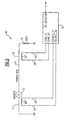
Figure 1 schematically illustrates a first,prior art circuit 18a for detecting a bus fault using the "Differential Power" method. The circuit is compatible withtransducers Fig. 3 ). A current transformer ("CT") is an example of such a transducer. Although current transformers sense current, the current in the power bus in many applications is proportional to the power in the power bus, and therefore a current transformer may be used with the "Differential Power" method. The voltage acrossresistor 34 is proportional to a difference in current output of thetransducers signal conditioner 40a conditions thevoltage input signals difference signal 42 suitable for thecontrol module 44 to follow. Acontrol module 44 evaluates an amplitude of theconditioned difference signal 42, and if the amplitude is excessive (exceeds a first threshold), thecontrol module 44 indicates a bus fault. -
Figure 2 schematically illustrates a second,prior art circuit 18b for detecting a bus fault using the "Differential Power" method. Thecircuit 18b is compatible withtransducers Fig. 3 ).Signal conditioners 40b-c condition theinput signals transducers current signal 46 and aload current signal 48 suitable for acontrol module 50 to follow. Thecontrol module 50 determines a difference between an amplitude of each of thesignals control module 50 indicates a bus fault. - A circuit's reliability is improved by the use of BITE ("Built In Test Equipment"). BITE is circuitry built into a given circuit that verifies if the circuit is still functional. Without BIT ("Built In Test"), the probability of circuit failure is calculated over the life of the product or for the duration of time between scheduled maintenance, at which time the circuitry is tested. However, the reliability of a circuit using BITE is calculated over the period of time between BIT tests, which is often very brief. Thus, the decreased time period between tests offered by BITE significantly increases reliability. A feasible, cost effective method to BIT the
resistor 38 ofFigure 1 is not known within the industry. Thus, the circuitry offigure 2 can be made very reliable, as can much of the circuitry ofFigure 1 , but not theresistor 38 ofFigure 1 . - A technique often used in conjunction with BITE is to stimulate (abbreviated "STIM") the circuit to be tested. A STIM signal injects a known signal into the circuitry to be tested. Control circuitry (or software) verifies that the circuit produces the expected output signal while it is stimulated.
- The
circuit 18a ofFigure 1 stimulates thesignal conditioner 40a. Since thedifference signal 42 output of thesignal conditioner 40a is negligible during normal use while no bus faults exist, there is no way to distinguish a circuit that is failed from one that is correctly reporting no difference current, unless the circuit is stimulated. However, a feasible, cost effective method of stimulating theresistor 38 ofFigure 1 is not known. - The circuit of
Figure 2 does not require stimulation of thesignal conditioners 40b-c. Because the output of thesignal conditioners 40b-c are equal and non-zero during normal use, while no bus faults exist, the circuit can be verified to be working by verifying that the output values of thesignal conditioners 40b-c are equal and non-zero. - However, each of the
known circuits circuit 18a offigure 1 is less reliable than thecircuit 18b because if theresistor 38 ofFigure 1 fails, thecircuit 18b could erroneously fail to detect a difference between the source and load current and could therefore erroneously not indicate a bus fault. Also, as discussed above, a STIM signal cannot be used to verify that theresistor 34 is functioning properly. - The
circuit 18b ofFigure 2 is inherently less accurate than thecircuit 18a ofFigure 1 . Each circuit element introduces error, and since thecircuit 18b ofFigure 2 has multipleadditional signal conditioners 40b-c it can not be made as accurate as that ofFigure 1 , all other conditions being equal. Also, because the signalconditioning circuit module 40a ofFigure 1 operates on the difference signal, its error affects only the difference signal, whereas thesignal conditioners 40b-c ofFigure 2 operate onsource signal load signal circuit 18a. Thus, an error contributed by a given signal conditioning circuit module to thetotal circuit 18b is many times larger than inFigure 1 . - For example, suppose the
source current load current signal conditioners 40a-c is 1% and all other circuit elements are ideal (0% error). In this example, thecircuit 18a ofFigure 1 determines a voltage acrossresistor 34 corresponding to 1 amp and thesignal conditioner 40a processes that signal with ±1% error, potentially introducing an error of .01 Amps (1% of 1 Amp). Thecircuit 18b ofFigure 2 has a ±200% error, as thesignal conditioner 40b potentially introduces an error of 1 Amp (1% of 100 Amps), and thesignal conditioner 40c potentially introduces an error of 1 Amp (1% of 99 Amps), yielding an overall potential error of 2 Amps (200% of 1 Amp). - A method of determining a differential power condition includes comparing a voltage across a resistor to a first threshold. The voltage across the resistor is proportional to a difference between a first current and a second current. The method also includes comparing a difference between the first current and the second current to a second threshold. A differential power condition is determined in response to the voltage across the resistor exceeding the first threshold, the difference exceeding the second threshold, or both.
- A system for determining a differential power condition includes a first resistor electrically connected to a first input signal, a second resistor electrically connected to the first resistor and electrically connected to a second input signal, and a third resistor. The third resistor is electrically connected to the first resistor, the second resistor, and a common connection of the first input signal and the second input signal. A voltage across the third resistor is proportional to a difference between the first current and the second current. The system also includes a control module operable to determine a differential power condition in response to the voltage across the first resistor exceeding a first threshold, the difference between the first input signal and the second input signal exceeding a second threshold, or both.
- A system for determining a differential power condition includes an electric generator associated with a turbine engine of an aircraft and a load. The load is coupled to the electric generator via a power bus. The system also includes a first transducer, a second transducer, and a circuit for detecting a differential power condition. The first transducer outputs a first current having an amplitude proportional to a power flowing in the power bus at a first location associated with the electric generator. The second transducer outputs a second current having an amplitude proportional to the power flowing through the power bus at a second location associated with the load. The circuit for detecting a differential power condition includes a first resistor, a second resistor, a third resistor, and a control module. The first resistor is electrically connected to the first current. The second resistor is electrically connected to the first resistor and electrically connected to the second current. The third resistor is electrically connected to the first resistor, the second resistor, and a common connection of the first current and the second current. A voltage across the third resistor is proportional to a difference between the first current and the second current. The control module is operable to determine a differential power condition in response to the voltage across the first resistor exceeding a first threshold, the difference between the first current and the second current exceeding a second threshold, or both.
-
-
Figure 1 schematically illustrates a first, prior art circuit for detecting a differential power condition. -
Figure 2 schematically illustrates a second, prior art circuit for detecting a differential power condition. -
Figure 3 schematically illustrates a system that includes differential power bus fault protection. -
Figure 4 schematically illustrates an improved circuit for detecting a differential power condition. -
Figure 3 schematically illustrates asystem 10 that includes apower source 12, aload 14, andpower bus 16 that conveys power from thepower source 12 to theload 14. A first,source transducer 20 outputs asignal power source 12 into thepower bus 16 at afirst location 17. A second,load transducer 22 outputs asignal power bus 16 at asecond location 19 into the load 14 (a "line current"). In one example thetransducers signal signal system 10 includes acircuit 18 that is operable to detect a differential power condition in response to the transducer signals 24, 26, 28, 30. In one example thesystem 10 corresponds to an aircraft, thesource 12 corresponds to an electric generator associated with a turbine engine, and thecircuit 18 is duplicated for each of a plurality of phases of current. Of course, it is understood that thecircuit 18 could be used in other applications withother power sources 12 and with other types of power buses. - The
circuit 18 includes inputs SOURCE_X1 and SOURCE_X2 that together bring thecurrent signal source transducer 20 into thecircuit 18. Thecircuit 18 also includes inputs LOAD_X1 and LOAD_X2 that together bring thecurrent signal load transducer 22 into thecircuit 18. -
Figure 4 schematically illustrates acircuit 18c operable to detect a bus fault using the "Differential Power" method. Thecircuit 18c incorporates elements of each of thecircuits circuit 18c includes a plurality ofresistors circuit 18c to sense the source current (24, 26), the load current (28, 30), and a difference between the source current and load current, while contributing only a negligible error. As in thecircuit 18a, thecircuit 18c is compatible withtransducers resistor 34 has a resistance that is greater than a resistance of either of theresistors -
Resistor 34 is electrically connected at one end toresistors resistor 34 is proportional to an amplitude of the difference between the source transducercurrent signal current signal locations signal conditioner 40a conditions voltage input signals 51, 52 and provides adifference signal 42. The conditioning performed bysignal conditioner 40a may include filtering, buffering, attenuating, or amplifying thesignals control module 60 evaluates an amplitude of thedifference signal 42, and indicates a bus fault if the difference exceeds a first threshold by outputting a fault signal 62 ("DP_DETECTED"). In one example, thecontrol module 60 only indicates a differential power condition if the difference exceeds the first threshold for a predetermined time period. - A voltage across
resistor 36 is proportional to an amplitude of the source transducercurrent signals power bus 16 atlocation 17. A voltage acrossresistor 38 is proportional to the amplitude of the load transducercurrent signal power bus 16 atlocation 19.Signal conditioner 40b conditions voltage signals 53, 54 emanating fromresistor 36 and provides a sourcecurrent signal 46 suitable for thecontrol module 60 to follow.Signal conditioner 40c conditions voltage signals 55, 56 emanating fromresistor 38 and provides a loadcurrent signal 48 suitable for thecontrol module 60 to follow. The conditioning performed bysignal conditioners 40a-c may include filtering, buffering, attenuating, or amplifying the signals 53-56. However, it is understood that other types of conditioning could be performed. Thecontrol module 60 determines a difference between thesignals control module 60 only indicates a differential power condition if the difference exceeds the second threshold for a predetermined time period. Thecontrol module 60 may include a microprocessor, analog circuitry, or other implementation technologies. In one example, thecontrol module 60 deenergizes thepower bus 16, thepower source 12, or both in response to determining a differential power condition. - Although the
signal conditioners 40a-c are represented by a single reference numeral, it is understood that they do not need to be identical, and could be designed differently. - The
control module 60 may also generate a stimulation signal 64 ("STIM") and evaluates the resulting output from the stimulated circuitry to verify that the circuitry is functional. Although all threesignal conditioners 40a-c are illustrated as having STIM inputs, it is understood that thesignal conditioners 40b-c may not use their STIM inputs in thecircuit 18c, and it is understood that the STIM input is an optional feature for thesignal conditioners 40a-c. - The thresholds, timing and filtering applied to the
signals source 12,load 14, power bus 16), thetransducers circuit 18c (resistors signal conditioners 40a-c, and the control module 60). One aspect of the "coordination" could be to apply a larger threshold to the difference of the source and load signals than to the difference signal. That is, the second threshold may be set such that the second threshold is greater than the first threshold. The thresholds as a goal may be set to be as low as the components of the system 10 (source 12,load 14, power bus 16), thetransducers circuit 18c (resistors signal conditioners 40a-c, and the control module 60) will allow without undue risk of false indications. - Another aspect of the "coordination" could be to perform additional filtering of the difference of the source and load result, such that brief transients are filtered from the result to prevent false DP indications. A third aspect of the "coordination" could be "debounce," which is a time delay such that the difference of the source and load signals must exceed a threshold for a continuous time period before a condition is indicated. The details of the coordination are highly dependent on the specific characteristics of the components of the system 10 (
source 12,load 14, power bus 16), thetransducers circuit 18c (resistors signal conditioners 40a-c, and the control module 60). - The
circuit 18c ofFigure 4 provides a redundancy not present in either of thecircuits resistor 34 ofcircuit 18a were to fail or become shorted, thecircuit 18a could erroneously ignore DP conditions by falsely indicating no difference between thesignals signals circuit 18c provides a redundancy throughsignal conditioners 40b-c and signals 46, 48. Also, accuracy is not compromised in thecircuit 18c because even though the second threshold may be larger than the first threshold and therefore unable to detect some DP conditions, the first threshold will still detect the DP conditions with full accuracy. - The
circuit 18c is able to detect faults early while they are still benign, and yet is highly reliable in that a latent circuitry failure will not cause thecircuit 18c to fail to detect a fault. The term "latent failure" refers to when a circuit component fails, but does not cause a system effect until later, perhaps when the effect is critical. An example of a latent failure is a circuit breaker shorting closed, as the breaker failure may have no effect on a system until a circuit associated with the breaker is overloaded and the system relies upon the breaker for protection. - The
circuit 18c is widely applicable to applications other than electrical power buses that deliver electrical power. For example, thesource 12 could be a source of water, thepower bus 16 could be a pipe that delivers water from awater source 12 to a hydro-dynamic load 14, thetransducers output signals circuit 18c could be implemented to indicate a difference in flow rate betweenlocations - Suitable transducers must be selected based upon the type of power bus and the application. With the
electrical power bus 16 ofFigure 3 and the described aviation application,transducers bus 16 is proportional to the power in thebus 16. With other electrical power buses a current transducer may not be sufficient, and a power transducer or power sensing device may be required. With other types of power buses the power sensing device may be required to sense power in other forms such as fluid-dynamic power, radiated power, mechanical power, etc. - For a fluid dynamic power bus, a suitable transducer may sense flow rate. Flow rate is not power, but may be proportional to power. With a power bus that transfers power in the form of steam, it may not be sufficient to sense only flow rate, and may be necessary to sense power, which in this example would be a function of mass flow rate, pressure and temperature.
- Although a preferred embodiment of this invention has been disclosed, a worker of ordinary skill in this art would recognize that certain modifications would come within the scope of this invention. For that reason, the following claims should be studied to determine the true scope and content of this invention.
Claims (15)
- A method of determining a differential power condition comprising:comparing a voltage across a resistor (34) to a first threshold, wherein the voltage across the resistor is proportional to a difference between a first current and a second current;comparing a difference between the first current and the second current to a second threshold; anddetermining a differential power condition in response to at least one of the voltage across the resistor exceeding the first threshold, the difference exceeding the second threshold, or both.
- The method of claim 1, wherein the first current is output by a first transducer (20) and has an output amplitude proportional to a power flowing in a bus (16) at a first location (17), and wherein the second current is output by a second transducer (22) and has an output amplitude proportional to the power flowing in the bus at a second location (19); preferably wherein the first location is associated with a power source (12) and the second location is associated with a load (14); and further preferably wherein the differential power condition indicates that an amount of power leaving the source is not equal to an amount of power arriving at the load.
- The method of claim 2, further comprising:de-energizing at least one of the power bus (16) and the power source (12) in response to determining a differential power condition.
- The method of claim 1, 2 or 3 further comprising:determining the first current (46);determining the second current (48); anddetermining the difference between the first current and the second current.
- The method of claim 1, 2, 3 or 4 wherein the second threshold is greater than the first threshold.
- The method of any preceding claim, further comprising:assigning values to the first threshold and the second threshold based on characteristics of system and circuit components.
- The method of any preceding claim, wherein the step of determining a differential power condition is only performed if at least one of the first threshold and the second threshold is exceeded for a predetermined time period.
- The method of any preceding claim, further comprising:conditioning (40b) a signal corresponding to the first current;conditioning (40c) a signal corresponding to the second current; andconditioning (40a) a signal corresponding to the voltage across the resistor; and preferably wherein the conditioning includes at least one of filtering, buffering, attenuating, and amplifying.
- The method of claim 8, further comprising:coordinating the conditioning steps based on characteristics of system and circuit components; andcoordinating a timing of the steps of comparing a difference between a first current and a second current to a first threshold, comparing a voltage across a resistor to a second threshold, and determining a differential power condition based on characteristics of system and circuit components.
- The method of any preceding claim, wherein the steps of comparing a difference between a first current and a second current to a first threshold, comparing a voltage across a resistor to a second threshold, and determining a differential power condition are performed for each of a plurality of phases of current.
- A system (10) for determining a differential power condition comprising:a first resistor (36) electrically connected to a first input signal;a second resistor (38) electrically connected to the first resistor and electrically connected to a second input signal;a third resistor (34) electrically connected to the first resistor, the second resistor, and a common connection of the first input signal and the second input signal, wherein a voltage across the third resistor is proportional to a difference between the first input signal and the second input signal; anda control module (60) operable to determine a differential power condition in response to the voltage across the first resistor exceeding a first threshold, the difference between the first input signal and the second input signal exceeding a second threshold, or both.
- The system of claim 11, wherein the second threshold is greater than the first threshold.
- The system of claim 11 or 12, wherein the first input signal has an amplitude proportional to a current flowing in a power bus (16) at a first location (17) associated with a power source (12), and wherein the second input signal has an amplitude proportional to the current flowing in the power bus at a second location (19) associated with a load (14).
- The system of claim 11, 12 or 13 further comprising:a first signal conditioner (40b) operable to provide a first conditioned signal (46) that is proportional to the first input signal;a second signal conditioner (40c) operable to provide a second conditioned signal (48) that is proportional to the second input signal; anda third signal conditioner (40a) operable to provide a difference current signal (42) that is proportional to a difference between the first input signal and the second input signal.
- An electrical system comprising:an electric generator (12) associated with a turbine engine of an aircraft;a load (14) coupled to the electric generator via a power bus (16);a first current transducer (20) that outputs a first current having an amplitude proportional to a current flowing in the power bus at a first location (17) associated with the electric generator;a second current transducer (22) that outputs a second current having an amplitude proportional to the current flowing through the power bus at a second location (19) associated with the load (14); anda circuit for detecting a differential power condition as claimed in claim 11, 12, 13 or 14;the first current forming said first input signal,and the second current forming said second input signal.
Applications Claiming Priority (1)
| Application Number | Priority Date | Filing Date | Title |
|---|---|---|---|
| US12/247,543 US8072225B2 (en) | 2008-10-08 | 2008-10-08 | Differential power detection |
Publications (3)
| Publication Number | Publication Date |
|---|---|
| EP2175537A2 true EP2175537A2 (en) | 2010-04-14 |
| EP2175537A3 EP2175537A3 (en) | 2012-11-21 |
| EP2175537B1 EP2175537B1 (en) | 2017-07-19 |
Family
ID=41478727
Family Applications (1)
| Application Number | Title | Priority Date | Filing Date |
|---|---|---|---|
| EP09251411.6A Active EP2175537B1 (en) | 2008-10-08 | 2009-05-28 | Differential power detection |
Country Status (2)
| Country | Link |
|---|---|
| US (1) | US8072225B2 (en) |
| EP (1) | EP2175537B1 (en) |
Family Cites Families (13)
| Publication number | Priority date | Publication date | Assignee | Title |
|---|---|---|---|---|
| US4321645A (en) * | 1980-02-26 | 1982-03-23 | Sundstrand Corporation | Differential fault current protection of a multiprocessor controlled electric power generating system |
| US4908565A (en) * | 1987-02-18 | 1990-03-13 | Sundstrand Corporation | Power generating system |
| US4937462A (en) * | 1989-01-23 | 1990-06-26 | Sundstrand Corporation | No break power transfer control for a VSCF power generating system |
| US5521787A (en) * | 1993-07-28 | 1996-05-28 | Sundstrand Corporation | Differential current fault protection for a system utilizing a power conversion unit exhibiting balanced load characteristics |
| FR2714771B1 (en) * | 1994-01-06 | 1996-02-02 | Merlin Gerin | Differential protection device for a power transformer. |
| US5539602A (en) * | 1994-10-19 | 1996-07-23 | Gte Airfone Incorporated | Ground fault interrupter |
| US5995911A (en) * | 1997-02-12 | 1999-11-30 | Power Measurement Ltd. | Digital sensor apparatus and system for protection, control, and management of electricity distribution systems |
| US6356421B1 (en) * | 1999-11-29 | 2002-03-12 | Schweitzer Engineering Labs., Inc. | System for power transformer differential protection |
| DE19959777A1 (en) * | 1999-12-07 | 2001-06-28 | Siemens Ag | Differential protection method |
| US6518767B1 (en) * | 2000-10-19 | 2003-02-11 | Schweitzer Engineering Laboratories, Inc. | Line differential protection system for a power transmission line |
| US6590397B2 (en) * | 2000-10-19 | 2003-07-08 | Schweitzer Engineering Laboratories, Inc. | Line differential protection system for a power transmission line |
| US7362551B2 (en) * | 2001-02-01 | 2008-04-22 | Hydro-Aire, Inc. | Aircraft applicable circuit imbalance detection and circuit interrupter and packaging thereof |
| GB0300507D0 (en) * | 2003-01-09 | 2003-02-12 | Goodrich Corp | Apparatus for and method of ground fault detection |
-
2008
- 2008-10-08 US US12/247,543 patent/US8072225B2/en active Active
-
2009
- 2009-05-28 EP EP09251411.6A patent/EP2175537B1/en active Active
Also Published As
| Publication number | Publication date |
|---|---|
| US8072225B2 (en) | 2011-12-06 |
| US20100085059A1 (en) | 2010-04-08 |
| EP2175537A3 (en) | 2012-11-21 |
| EP2175537B1 (en) | 2017-07-19 |
Similar Documents
| Publication | Publication Date | Title |
|---|---|---|
| CN109416382B (en) | Ground Loss Detection Circuit | |
| AU2020202694B2 (en) | Absence of voltage detection device | |
| EP2953225B1 (en) | Method of detection and isolation of faults within power conversion and distribution systems | |
| CN104583787B (en) | Devices for diagnosing circuit assemblies | |
| US10393789B2 (en) | Ground fault tester | |
| US20200028349A1 (en) | System and method for detecting arc faults | |
| US10288664B2 (en) | Methods and devices for detecting a disconnection of a protective conductor connection | |
| EP3262428A1 (en) | Method and apparatus for an electrical fault detecting system for a cable | |
| US20100289499A1 (en) | Monitoring device for monitoring a terminal of a terminal component | |
| US8305723B2 (en) | Motor drive ground fault detection | |
| JP6874125B2 (en) | Electronic control device | |
| CN103069287B (en) | For the method and apparatus that parasitic current detects | |
| EP3360217A1 (en) | Fault current protection device for monitoring an electric load for a vehicle, and method for carrying out a self-test of a fault current sensor | |
| CN106159912A (en) | For closing the method and device of the device part presenting insulation fault in ungrounded electric power system | |
| JP6932964B2 (en) | DC power supply circuit disconnection discriminator and wiring discriminator | |
| EP2175537B1 (en) | Differential power detection | |
| US7183934B2 (en) | Diagnostic circuit | |
| AU2013245827B2 (en) | Neutral grounding resistor monitor | |
| KR101713966B1 (en) | Communication diagnostic device of train control apparatus | |
| CN102804307B (en) | Circuit for detecting contactor position in a turbine engine | |
| US9841798B2 (en) | Battery, battery controller, and method for the secured digital transmission of current measurement values | |
| KR102944001B1 (en) | Method for detecting ground connection loss, controller, and brake system | |
| US20070262779A1 (en) | Detection of unbalanced power feed conditions | |
| KR102844019B1 (en) | relay module unit for controlling and monitoring the electric power facilities | |
| JP2015021954A (en) | Current controller |
Legal Events
| Date | Code | Title | Description |
|---|---|---|---|
| PUAI | Public reference made under article 153(3) epc to a published international application that has entered the european phase |
Free format text: ORIGINAL CODE: 0009012 |
|
| AK | Designated contracting states |
Kind code of ref document: A2 Designated state(s): AT BE BG CH CY CZ DE DK EE ES FI FR GB GR HR HU IE IS IT LI LT LU LV MC MK MT NL NO PL PT RO SE SI SK TR |
|
| AX | Request for extension of the european patent |
Extension state: AL BA RS |
|
| RIC1 | Information provided on ipc code assigned before grant |
Ipc: H02H 3/28 20060101AFI20120907BHEP |
|
| PUAL | Search report despatched |
Free format text: ORIGINAL CODE: 0009013 |
|
| RIC1 | Information provided on ipc code assigned before grant |
Ipc: H02H 3/28 20060101AFI20121002BHEP |
|
| AK | Designated contracting states |
Kind code of ref document: A3 Designated state(s): AT BE BG CH CY CZ DE DK EE ES FI FR GB GR HR HU IE IS IT LI LT LU LV MC MK MT NL NO PL PT RO SE SI SK TR |
|
| AX | Request for extension of the european patent |
Extension state: AL BA RS |
|
| RIC1 | Information provided on ipc code assigned before grant |
Ipc: H02H 3/28 20060101AFI20121012BHEP |
|
| 17P | Request for examination filed |
Effective date: 20130422 |
|
| 17Q | First examination report despatched |
Effective date: 20150209 |
|
| GRAP | Despatch of communication of intention to grant a patent |
Free format text: ORIGINAL CODE: EPIDOSNIGR1 |
|
| INTG | Intention to grant announced |
Effective date: 20170202 |
|
| GRAS | Grant fee paid |
Free format text: ORIGINAL CODE: EPIDOSNIGR3 |
|
| GRAA | (expected) grant |
Free format text: ORIGINAL CODE: 0009210 |
|
| AK | Designated contracting states |
Kind code of ref document: B1 Designated state(s): AT BE BG CH CY CZ DE DK EE ES FI FR GB GR HR HU IE IS IT LI LT LU LV MC MK MT NL NO PL PT RO SE SI SK TR |
|
| REG | Reference to a national code |
Ref country code: GB Ref legal event code: FG4D |
|
| REG | Reference to a national code |
Ref country code: CH Ref legal event code: EP |
|
| REG | Reference to a national code |
Ref country code: IE Ref legal event code: FG4D |
|
| REG | Reference to a national code |
Ref country code: AT Ref legal event code: REF Ref document number: 911253 Country of ref document: AT Kind code of ref document: T Effective date: 20170815 |
|
| REG | Reference to a national code |
Ref country code: DE Ref legal event code: R096 Ref document number: 602009047188 Country of ref document: DE |
|
| REG | Reference to a national code |
Ref country code: NL Ref legal event code: MP Effective date: 20170719 |
|
| REG | Reference to a national code |
Ref country code: LT Ref legal event code: MG4D |
|
| REG | Reference to a national code |
Ref country code: AT Ref legal event code: MK05 Ref document number: 911253 Country of ref document: AT Kind code of ref document: T Effective date: 20170719 |
|
| PG25 | Lapsed in a contracting state [announced via postgrant information from national office to epo] |
Ref country code: NL Free format text: LAPSE BECAUSE OF FAILURE TO SUBMIT A TRANSLATION OF THE DESCRIPTION OR TO PAY THE FEE WITHIN THE PRESCRIBED TIME-LIMIT Effective date: 20170719 Ref country code: FI Free format text: LAPSE BECAUSE OF FAILURE TO SUBMIT A TRANSLATION OF THE DESCRIPTION OR TO PAY THE FEE WITHIN THE PRESCRIBED TIME-LIMIT Effective date: 20170719 Ref country code: NO Free format text: LAPSE BECAUSE OF FAILURE TO SUBMIT A TRANSLATION OF THE DESCRIPTION OR TO PAY THE FEE WITHIN THE PRESCRIBED TIME-LIMIT Effective date: 20171019 Ref country code: HR Free format text: LAPSE BECAUSE OF FAILURE TO SUBMIT A TRANSLATION OF THE DESCRIPTION OR TO PAY THE FEE WITHIN THE PRESCRIBED TIME-LIMIT Effective date: 20170719 Ref country code: AT Free format text: LAPSE BECAUSE OF FAILURE TO SUBMIT A TRANSLATION OF THE DESCRIPTION OR TO PAY THE FEE WITHIN THE PRESCRIBED TIME-LIMIT Effective date: 20170719 Ref country code: SE Free format text: LAPSE BECAUSE OF FAILURE TO SUBMIT A TRANSLATION OF THE DESCRIPTION OR TO PAY THE FEE WITHIN THE PRESCRIBED TIME-LIMIT Effective date: 20170719 Ref country code: LT Free format text: LAPSE BECAUSE OF FAILURE TO SUBMIT A TRANSLATION OF THE DESCRIPTION OR TO PAY THE FEE WITHIN THE PRESCRIBED TIME-LIMIT Effective date: 20170719 |
|
| PG25 | Lapsed in a contracting state [announced via postgrant information from national office to epo] |
Ref country code: LV Free format text: LAPSE BECAUSE OF FAILURE TO SUBMIT A TRANSLATION OF THE DESCRIPTION OR TO PAY THE FEE WITHIN THE PRESCRIBED TIME-LIMIT Effective date: 20170719 Ref country code: PL Free format text: LAPSE BECAUSE OF FAILURE TO SUBMIT A TRANSLATION OF THE DESCRIPTION OR TO PAY THE FEE WITHIN THE PRESCRIBED TIME-LIMIT Effective date: 20170719 Ref country code: IS Free format text: LAPSE BECAUSE OF FAILURE TO SUBMIT A TRANSLATION OF THE DESCRIPTION OR TO PAY THE FEE WITHIN THE PRESCRIBED TIME-LIMIT Effective date: 20171119 Ref country code: GR Free format text: LAPSE BECAUSE OF FAILURE TO SUBMIT A TRANSLATION OF THE DESCRIPTION OR TO PAY THE FEE WITHIN THE PRESCRIBED TIME-LIMIT Effective date: 20171020 Ref country code: BG Free format text: LAPSE BECAUSE OF FAILURE TO SUBMIT A TRANSLATION OF THE DESCRIPTION OR TO PAY THE FEE WITHIN THE PRESCRIBED TIME-LIMIT Effective date: 20171019 Ref country code: ES Free format text: LAPSE BECAUSE OF FAILURE TO SUBMIT A TRANSLATION OF THE DESCRIPTION OR TO PAY THE FEE WITHIN THE PRESCRIBED TIME-LIMIT Effective date: 20170719 |
|
| REG | Reference to a national code |
Ref country code: DE Ref legal event code: R097 Ref document number: 602009047188 Country of ref document: DE |
|
| REG | Reference to a national code |
Ref country code: FR Ref legal event code: PLFP Year of fee payment: 10 |
|
| PG25 | Lapsed in a contracting state [announced via postgrant information from national office to epo] |
Ref country code: DK Free format text: LAPSE BECAUSE OF FAILURE TO SUBMIT A TRANSLATION OF THE DESCRIPTION OR TO PAY THE FEE WITHIN THE PRESCRIBED TIME-LIMIT Effective date: 20170719 Ref country code: RO Free format text: LAPSE BECAUSE OF FAILURE TO SUBMIT A TRANSLATION OF THE DESCRIPTION OR TO PAY THE FEE WITHIN THE PRESCRIBED TIME-LIMIT Effective date: 20170719 Ref country code: CZ Free format text: LAPSE BECAUSE OF FAILURE TO SUBMIT A TRANSLATION OF THE DESCRIPTION OR TO PAY THE FEE WITHIN THE PRESCRIBED TIME-LIMIT Effective date: 20170719 |
|
| PLBE | No opposition filed within time limit |
Free format text: ORIGINAL CODE: 0009261 |
|
| STAA | Information on the status of an ep patent application or granted ep patent |
Free format text: STATUS: NO OPPOSITION FILED WITHIN TIME LIMIT |
|
| PG25 | Lapsed in a contracting state [announced via postgrant information from national office to epo] |
Ref country code: IT Free format text: LAPSE BECAUSE OF FAILURE TO SUBMIT A TRANSLATION OF THE DESCRIPTION OR TO PAY THE FEE WITHIN THE PRESCRIBED TIME-LIMIT Effective date: 20170719 Ref country code: SK Free format text: LAPSE BECAUSE OF FAILURE TO SUBMIT A TRANSLATION OF THE DESCRIPTION OR TO PAY THE FEE WITHIN THE PRESCRIBED TIME-LIMIT Effective date: 20170719 Ref country code: EE Free format text: LAPSE BECAUSE OF FAILURE TO SUBMIT A TRANSLATION OF THE DESCRIPTION OR TO PAY THE FEE WITHIN THE PRESCRIBED TIME-LIMIT Effective date: 20170719 |
|
| 26N | No opposition filed |
Effective date: 20180420 |
|
| PG25 | Lapsed in a contracting state [announced via postgrant information from national office to epo] |
Ref country code: SI Free format text: LAPSE BECAUSE OF FAILURE TO SUBMIT A TRANSLATION OF THE DESCRIPTION OR TO PAY THE FEE WITHIN THE PRESCRIBED TIME-LIMIT Effective date: 20170719 |
|
| REG | Reference to a national code |
Ref country code: DE Ref legal event code: R119 Ref document number: 602009047188 Country of ref document: DE |
|
| REG | Reference to a national code |
Ref country code: CH Ref legal event code: PL |
|
| REG | Reference to a national code |
Ref country code: BE Ref legal event code: MM Effective date: 20180531 |
|
| PG25 | Lapsed in a contracting state [announced via postgrant information from national office to epo] |
Ref country code: MC Free format text: LAPSE BECAUSE OF FAILURE TO SUBMIT A TRANSLATION OF THE DESCRIPTION OR TO PAY THE FEE WITHIN THE PRESCRIBED TIME-LIMIT Effective date: 20170719 |
|
| REG | Reference to a national code |
Ref country code: IE Ref legal event code: MM4A |
|
| PG25 | Lapsed in a contracting state [announced via postgrant information from national office to epo] |
Ref country code: LI Free format text: LAPSE BECAUSE OF NON-PAYMENT OF DUE FEES Effective date: 20180531 Ref country code: CH Free format text: LAPSE BECAUSE OF NON-PAYMENT OF DUE FEES Effective date: 20180531 |
|
| PG25 | Lapsed in a contracting state [announced via postgrant information from national office to epo] |
Ref country code: LU Free format text: LAPSE BECAUSE OF NON-PAYMENT OF DUE FEES Effective date: 20180528 |
|
| PG25 | Lapsed in a contracting state [announced via postgrant information from national office to epo] |
Ref country code: DE Free format text: LAPSE BECAUSE OF NON-PAYMENT OF DUE FEES Effective date: 20181201 Ref country code: IE Free format text: LAPSE BECAUSE OF NON-PAYMENT OF DUE FEES Effective date: 20180528 |
|
| PG25 | Lapsed in a contracting state [announced via postgrant information from national office to epo] |
Ref country code: BE Free format text: LAPSE BECAUSE OF NON-PAYMENT OF DUE FEES Effective date: 20180531 |
|
| PG25 | Lapsed in a contracting state [announced via postgrant information from national office to epo] |
Ref country code: MT Free format text: LAPSE BECAUSE OF NON-PAYMENT OF DUE FEES Effective date: 20180528 |
|
| PG25 | Lapsed in a contracting state [announced via postgrant information from national office to epo] |
Ref country code: TR Free format text: LAPSE BECAUSE OF FAILURE TO SUBMIT A TRANSLATION OF THE DESCRIPTION OR TO PAY THE FEE WITHIN THE PRESCRIBED TIME-LIMIT Effective date: 20170719 |
|
| PG25 | Lapsed in a contracting state [announced via postgrant information from national office to epo] |
Ref country code: HU Free format text: LAPSE BECAUSE OF FAILURE TO SUBMIT A TRANSLATION OF THE DESCRIPTION OR TO PAY THE FEE WITHIN THE PRESCRIBED TIME-LIMIT; INVALID AB INITIO Effective date: 20090528 Ref country code: PT Free format text: LAPSE BECAUSE OF FAILURE TO SUBMIT A TRANSLATION OF THE DESCRIPTION OR TO PAY THE FEE WITHIN THE PRESCRIBED TIME-LIMIT Effective date: 20170719 |
|
| PG25 | Lapsed in a contracting state [announced via postgrant information from national office to epo] |
Ref country code: CY Free format text: LAPSE BECAUSE OF FAILURE TO SUBMIT A TRANSLATION OF THE DESCRIPTION OR TO PAY THE FEE WITHIN THE PRESCRIBED TIME-LIMIT Effective date: 20170719 Ref country code: MK Free format text: LAPSE BECAUSE OF NON-PAYMENT OF DUE FEES Effective date: 20170719 |
|
| P01 | Opt-out of the competence of the unified patent court (upc) registered |
Effective date: 20230522 |
|
| PGFP | Annual fee paid to national office [announced via postgrant information from national office to epo] |
Ref country code: GB Payment date: 20250423 Year of fee payment: 17 |
|
| PGFP | Annual fee paid to national office [announced via postgrant information from national office to epo] |
Ref country code: FR Payment date: 20250424 Year of fee payment: 17 |