EP2175529A1 - Inner conductor sealing insulator for coaxial connector - Google Patents
Inner conductor sealing insulator for coaxial connector Download PDFInfo
- Publication number
- EP2175529A1 EP2175529A1 EP09012084A EP09012084A EP2175529A1 EP 2175529 A1 EP2175529 A1 EP 2175529A1 EP 09012084 A EP09012084 A EP 09012084A EP 09012084 A EP09012084 A EP 09012084A EP 2175529 A1 EP2175529 A1 EP 2175529A1
- Authority
- EP
- European Patent Office
- Prior art keywords
- insulator
- seal
- inner conductor
- connector
- coaxial cable
- Prior art date
- Legal status (The legal status is an assumption and is not a legal conclusion. Google has not performed a legal analysis and makes no representation as to the accuracy of the status listed.)
- Granted
Links
Images




Classifications
-
- H—ELECTRICITY
- H01—ELECTRIC ELEMENTS
- H01R—ELECTRICALLY-CONDUCTIVE CONNECTIONS; STRUCTURAL ASSOCIATIONS OF A PLURALITY OF MUTUALLY-INSULATED ELECTRICAL CONNECTING ELEMENTS; COUPLING DEVICES; CURRENT COLLECTORS
- H01R24/00—Two-part coupling devices, or either of their cooperating parts, characterised by their overall structure
- H01R24/38—Two-part coupling devices, or either of their cooperating parts, characterised by their overall structure having concentrically or coaxially arranged contacts
- H01R24/40—Two-part coupling devices, or either of their cooperating parts, characterised by their overall structure having concentrically or coaxially arranged contacts specially adapted for high frequency
-
- H—ELECTRICITY
- H01—ELECTRIC ELEMENTS
- H01R—ELECTRICALLY-CONDUCTIVE CONNECTIONS; STRUCTURAL ASSOCIATIONS OF A PLURALITY OF MUTUALLY-INSULATED ELECTRICAL CONNECTING ELEMENTS; COUPLING DEVICES; CURRENT COLLECTORS
- H01R13/00—Details of coupling devices of the kinds covered by groups H01R12/70 or H01R24/00 - H01R33/00
- H01R13/46—Bases; Cases
- H01R13/52—Dustproof, splashproof, drip-proof, waterproof, or flameproof cases
-
- H—ELECTRICITY
- H01—ELECTRIC ELEMENTS
- H01R—ELECTRICALLY-CONDUCTIVE CONNECTIONS; STRUCTURAL ASSOCIATIONS OF A PLURALITY OF MUTUALLY-INSULATED ELECTRICAL CONNECTING ELEMENTS; COUPLING DEVICES; CURRENT COLLECTORS
- H01R13/00—Details of coupling devices of the kinds covered by groups H01R12/70 or H01R24/00 - H01R33/00
- H01R13/02—Contact members
- H01R13/03—Contact members characterised by the material, e.g. plating, or coating materials
-
- H—ELECTRICITY
- H01—ELECTRIC ELEMENTS
- H01R—ELECTRICALLY-CONDUCTIVE CONNECTIONS; STRUCTURAL ASSOCIATIONS OF A PLURALITY OF MUTUALLY-INSULATED ELECTRICAL CONNECTING ELEMENTS; COUPLING DEVICES; CURRENT COLLECTORS
- H01R4/00—Electrically-conductive connections between two or more conductive members in direct contact, i.e. touching one another; Means for effecting or maintaining such contact; Electrically-conductive connections having two or more spaced connecting locations for conductors and using contact members penetrating insulation
- H01R4/58—Electrically-conductive connections between two or more conductive members in direct contact, i.e. touching one another; Means for effecting or maintaining such contact; Electrically-conductive connections having two or more spaced connecting locations for conductors and using contact members penetrating insulation characterised by the form or material of the contacting members
- H01R4/62—Connections between conductors of different materials; Connections between or with aluminium or steel-core aluminium conductors
Definitions
- the invention relates to electrical connectors for coaxial cable. More particularly the invention relates to a coaxial cable insulator that provides an environmental seal for at least the inner conductor to inner contact electrical interconnection.
- Prior coaxial connectors typically rely upon multiple seals between the connector, coaxial cable and/or interface element joints to prevent entry of moisture and/or humid air.
- the plurality of environmental seals significantly increases the complexity of the coaxial connector manufacture as well as assembly and installation procedures.
- Figure 1 is a schematic isometric 90 degree cut-away view of a first exemplary insulator.
- Figure 2 is a schematic isometric 90 degree cut-away view of figure 1 , including an inner contact.
- Figure 3 is a schematic cut-away side view of figure 1 .
- Figure 4 is a schematic cut-away side view of an insulator demonstrating over-molded seals.
- Figure 5 is a schematic cut-away side view of a first exemplary coaxial cable assembly with an insulator according to the invention, prepared for coaxial cable attachment.
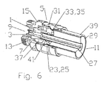
- Figure 6 is a schematic isometric 90 degree cut-away view of the embodiment of Figure 5 , with coaxial cable attached.
- Figure 7 is a schematic isometric 90 degree cut-away view of a second exemplary embodiment of a coaxial cable assembly, with coaxial cable attached.
- Figure 8 is a schematic cut-away side view of figure 7 .
- Figure 9 is a close-up view of area A of figure 8 .
- Prior coaxial cables typically have inner and outer conductors made from copper and copper alloy.
- the inventor has recognized that new coaxial cable configurations and/or materials such as inner and/or outer conductors of aluminum and/or aluminum with copper or other metallic outer coating may require improved protection of the electrical interconnection, especially when these materials are connected to the dissimilar metals commonly applied to electrical connectors.
- the environmental seals in prior coaxial connectors are typically located around entry paths through the connector body and therefore do not protect the electrical interconnection between the inner conductor and the inner contact from any moisture which (a) may migrate past environmental seals of the connector body, (b) is sealed within the connector during installation and/or (c) may migrate to the electrical interconnection area along the inside of the coaxial cable.
- An installation error and/or failure of any one of these connector body environmental seals may allow moisture and/or humid air to enter the connection areas of the connector where it can pool and cause corrosion resulting in significant performance degradation of the electrical connections.
- An insulator 1 for supporting an inner contact 3 ( figure 2 ) within a coaxial cable connector assembly 5 ( figures 5-9 ) is formed as a monolithic dielectric body 7 with a connector end 9 and a cable end 11 (these end designations along the insulator 1 longitudinal axis are hereinafter similarly applied to individual elements of the insulator 1, and associated coaxial cable connector assembly 5) provided with a mounting portion 13 proximate the connector end 9.
- the outer diameter of the mounting portion 13 may be dimensioned to seat the insulator 1 within a connector body 15 of the coaxial cable connector assembly 5.
- a bore 17 through the dielectric body 7 is dimensioned to seat the inner contact 3 therein, retaining the inner contact 3 coaxial with the connector body 15.
- the bore 17 may be formed with an inner diameter that increases between the connector end 9 and the cable end 11, for example via a step 19 against which an increased diameter contact portion 21 of the inner contact 3 bottoms, preventing further movement of the inner contact 3 towards the connector end 9.
- An annular first seal groove 23 is provided in an inner diameter of the bore 17 proximate the cable end 11.
- An inner conductor seal 25 is disposed in the first seal groove 23, for example an o-ring or other form of annular gasket.
- the inner conductor seal 25 may be over-molded upon the dielectric body 7 ( figure 4 ).
- the inner conductor seal 25 is dimensioned to seal between the insulator 1 and the inner conductor 27 as the inner conductor 27 is inserted to couple with the inner contact 3.
- the insulator 1 may also be configured to provide a seal against the inner diameter of the outer conductor 29.
- an outer diameter aligning portion 31 of the dielectric body 7 proximate the cable end 11 may be provided with an annular second seal groove 33 around the outer diameter.
- the second seal groove 33 receives an outer conductor seal 35 dimensioned to seal between the insulator 1 and an inner diameter of the outer conductor 29 when the outer conductor 29 is coupled to the connector body 15.
- the outer conductor seal 35 may also be an o-ring or other form of annular gasket and/or may be over-molded directly upon the second seal groove 33.
- a material reduction groove may be located between the mounting portion 13 and the aligning portion 31.
- the diameter of the mounting portion 13 may be smaller than the diameter of the aligning portion 31.
- the aligning portion may be provided with step and/or ramp surfaces to align the outer conductor seal 35 with the outer conductor 29, for example where the outer conductor 29 inner diameter is the same as the inner diameter of a body bore of the connector body 15 at the cable end 11.
- an insulator 1 may also include a surface sealant 41 (notation 41 in the various figures indicating several possible general surface sealant 41 application area(s), as the surface sealant 41 may be applied in coating thicknesses that are too thin to graphically represent in the various figures) such as an oxidation and/or corrosion inhibitor coating or grease.
- a surface sealant 41 is the family of Dostex TM oxide inhibitors available from Dossert Corporation of Waterbury, Connecticut, US.
- the surface sealant 41 may be applied to the inner conductor seal 25 , outer conductor seal 29, first seal groove 23, second seal groove 33, inner contact 3, the cable end 11 of the bore 17 and/or the inner conductor 27.
- the surface sealant 41 is applied, for example to the inner conductor seal 25 and/or first seal groove 23, displacement of the inner conductor seal 25 into/against the first seal groove 23 as the inner conductor 27 is moved towards the inner contact 3 will spread a coating of the surface sealant 41 upon the inner conductor 27.
- the mechanical force of the inner contact 3 will displace the surface sealant 41 from the immediate area of the electrical interconnection, sealing the electrical interconnection from exposure to the atmosphere and any moisture that may be present.
- the surface sealant may be applied to exposed surfaces of the electrical interconnection area, coaxial cable connector assembly 5 and/or coaxial cable 39 as a manual step of a method for coupling the coaxial cable connector assembly 5 to the end of the coaxial cable 39.
- the present invention may be easily integrated with existing coaxial connector configurations with a minimum of engineering rework and/or tooling modification.
- the required modifications may be limited to the exchange of a conventional insulator configuration with an insulator 1 according to the invention.
- An insulator 1 according to the invention provides an improved environmental seal located proximate the electrical interconnection connection between the inner conductor 27 and the inner contact 3 thus reducing opportunities for connector failure due to corrosion and/or oxidation inherent in metals such as aluminum alloys when mechanically coupled to dissimilar metals.
- the insulator 1 according to the invention is especially suited for use in electrical connectors for a coaxial cable 39 with an aluminum inner conductor 11 having a copper or other metal coating about the outer diameter surface 9.
- the exposed end of the inner conductor 27 and the metal coating edge exposed by cable end preparation for coaxial cable connector assembly 5 attachment is protected from moisture and/or air exposure, opportunities for accelerated corrosion of the exposed aluminum and/or related delamination of the metal coating are reduced, especially when a surface sealant 41 is applied to the socket formed by the inner contact 3 and the bore 17 at the cable end 11 prior to insertion of the inner conductor 27, to further exclude air and/or moisture from the area of the electrical interconnection.
- the insulator 1 may be configured to provide a seal against the inner diameter of the outer conductor 29 thereby effectively isolating the coaxial cable connector assembly 5 from any moisture that may be present in or migrating along the inside of the coaxial cable 39.
- exemplary coaxial cable connector assembly 5 and coaxial cable 39 combinations are provided demonstrating outer conductor 29 threaded clamp retention configurations for annular corrugated ( figures 7-9 ) and smooth walled ( figures 5 and 6 ) coaxial cable(s) 39
- the insulator 1 is applicable to any desired coaxial cable connector assembly 5 and coaxial cable 39 combination.
Landscapes
- Connector Housings Or Holding Contact Members (AREA)
- Coupling Device And Connection With Printed Circuit (AREA)
Abstract
Description
- The invention relates to electrical connectors for coaxial cable. More particularly the invention relates to a coaxial cable insulator that provides an environmental seal for at least the inner conductor to inner contact electrical interconnection.
- Prior coaxial connectors typically rely upon multiple seals between the connector, coaxial cable and/or interface element joints to prevent entry of moisture and/or humid air. The plurality of environmental seals significantly increases the complexity of the coaxial connector manufacture as well as assembly and installation procedures.
- Competition within the coaxial cable and connector industry has focused attention upon improving electrical performance as well as reducing manufacturing, materials and installation costs.
- Therefore, it is an object of the invention to provide a method and apparatus that overcomes deficiencies in such prior art.
- The accompanying drawings, which are incorporated in and constitute a part of this specification, illustrate embodiments of the invention and, together with a general description of the invention given above, and the detailed description of the embodiments given below, serve to explain the principles of the invention.
-
Figure 1 is a schematic isometric 90 degree cut-away view of a first exemplary insulator. -
Figure 2 is a schematic isometric 90 degree cut-away view offigure 1 , including an inner contact. -
Figure 3 is a schematic cut-away side view offigure 1 . -
Figure 4 is a schematic cut-away side view of an insulator demonstrating over-molded seals. -
Figure 5 is a schematic cut-away side view of a first exemplary coaxial cable assembly with an insulator according to the invention, prepared for coaxial cable attachment. -
Figure 6 is a schematic isometric 90 degree cut-away view of the embodiment ofFigure 5 , with coaxial cable attached. -
Figure 7 is a schematic isometric 90 degree cut-away view of a second exemplary embodiment of a coaxial cable assembly, with coaxial cable attached. -
Figure 8 is a schematic cut-away side view offigure 7 . -
Figure 9 is a close-up view of area A offigure 8 . - Prior coaxial cables typically have inner and outer conductors made from copper and copper alloy. The inventor has recognized that new coaxial cable configurations and/or materials such as inner and/or outer conductors of aluminum and/or aluminum with copper or other metallic outer coating may require improved protection of the electrical interconnection, especially when these materials are connected to the dissimilar metals commonly applied to electrical connectors.
- The environmental seals in prior coaxial connectors are typically located around entry paths through the connector body and therefore do not protect the electrical interconnection between the inner conductor and the inner contact from any moisture which (a) may migrate past environmental seals of the connector body, (b) is sealed within the connector during installation and/or (c) may migrate to the electrical interconnection area along the inside of the coaxial cable.
- An installation error and/or failure of any one of these connector body environmental seals may allow moisture and/or humid air to enter the connection areas of the connector where it can pool and cause corrosion resulting in significant performance degradation of the electrical connections.
- In the case of metals such as aluminum, an oxide film is formed on surfaces exposed to atmosphere in a very short time (within seconds). Also, accelerated galvanic corrosion can occur between aluminum and other metals in presence of an electrolytic solution, such as water.
- In a coaxial connector incorporating an inner conductor sealing insulator according to the invention, local isolation of the interconnection area is provided, reducing the overall seal area required and improving the reliability of the environmental seal.
- An insulator 1 (best demonstrated in
figures 1-4 ) for supporting an inner contact 3 (figure 2 ) within a coaxial cable connector assembly 5 (figures 5-9 ) is formed as a monolithicdielectric body 7 with a connector end 9 and a cable end 11 (these end designations along theinsulator 1 longitudinal axis are hereinafter similarly applied to individual elements of theinsulator 1, and associated coaxial cable connector assembly 5) provided with amounting portion 13 proximate the connector end 9. The outer diameter of themounting portion 13 may be dimensioned to seat theinsulator 1 within aconnector body 15 of the coaxialcable connector assembly 5. - A
bore 17 through thedielectric body 7 is dimensioned to seat theinner contact 3 therein, retaining theinner contact 3 coaxial with theconnector body 15. Thebore 17 may be formed with an inner diameter that increases between the connector end 9 and thecable end 11, for example via astep 19 against which an increaseddiameter contact portion 21 of theinner contact 3 bottoms, preventing further movement of theinner contact 3 towards the connector end 9. - An annular
first seal groove 23 is provided in an inner diameter of thebore 17 proximate thecable end 11. Aninner conductor seal 25 is disposed in thefirst seal groove 23, for example an o-ring or other form of annular gasket. To improve theinner conductor seal 25 seal characteristics and/or minimize the chance for misplacing and/or unseating theinner conductor seal 25 during assembly and/or cable to connector installation, theinner conductor seal 25 may be over-molded upon the dielectric body 7 (figure 4 ). Theinner conductor seal 25 is dimensioned to seal between theinsulator 1 and theinner conductor 27 as theinner conductor 27 is inserted to couple with theinner contact 3. - Similar to the sealing of the electrical connection between the
inner conductor 27 and theinner contact 3, theinsulator 1 may also be configured to provide a seal against the inner diameter of theouter conductor 29. For example, an outerdiameter aligning portion 31 of thedielectric body 7 proximate thecable end 11 may be provided with an annularsecond seal groove 33 around the outer diameter. Thesecond seal groove 33 receives anouter conductor seal 35 dimensioned to seal between theinsulator 1 and an inner diameter of theouter conductor 29 when theouter conductor 29 is coupled to theconnector body 15. Theouter conductor seal 35 may also be an o-ring or other form of annular gasket and/or may be over-molded directly upon thesecond seal groove 33. - To reduce material costs and overall connector assembly weight, a material reduction groove may be located between the
mounting portion 13 and the aligningportion 31. Depending upon thecoaxial cable 39 dimensions and the selected connection interface for the coaxial cable connector assembly, the diameter of themounting portion 13 may be smaller than the diameter of the aligningportion 31. To locate theouter conductor seal 35 at a position for contacting the inner diameter of theouter conductor 29, theinsulator 1 may extend beyond theconnector body 15 at thecable end 11. Further, the aligning portion may be provided with step and/or ramp surfaces to align theouter conductor seal 35 with theouter conductor 29, for example where theouter conductor 29 inner diameter is the same as the inner diameter of a body bore of theconnector body 15 at thecable end 11. - In addition to seal design to prevent aluminum oxidation and/or corrosion, an
insulator 1 according to the invention may also include a surface sealant 41 (notation 41 in the various figures indicating several possiblegeneral surface sealant 41 application area(s), as thesurface sealant 41 may be applied in coating thicknesses that are too thin to graphically represent in the various figures) such as an oxidation and/or corrosion inhibitor coating or grease. An example of suitable surface sealant(s) is the family of Dostex ™ oxide inhibitors available from Dossert Corporation of Waterbury, Connecticut, US. - The
surface sealant 41 may be applied to theinner conductor seal 25 ,outer conductor seal 29,first seal groove 23,second seal groove 33,inner contact 3, thecable end 11 of thebore 17 and/or theinner conductor 27. - Where the
surface sealant 41 is applied, for example to theinner conductor seal 25 and/orfirst seal groove 23, displacement of theinner conductor seal 25 into/against thefirst seal groove 23 as theinner conductor 27 is moved towards theinner contact 3 will spread a coating of thesurface sealant 41 upon theinner conductor 27. When theinner contact 3 couples with thesurface sealant 41 coatedinner conductor 27, the mechanical force of theinner contact 3 will displace thesurface sealant 41 from the immediate area of the electrical interconnection, sealing the electrical interconnection from exposure to the atmosphere and any moisture that may be present. - Alternatively, the surface sealant may be applied to exposed surfaces of the electrical interconnection area, coaxial
cable connector assembly 5 and/orcoaxial cable 39 as a manual step of a method for coupling the coaxialcable connector assembly 5 to the end of thecoaxial cable 39. - One skilled in the art will appreciate that the present invention may be easily integrated with existing coaxial connector configurations with a minimum of engineering rework and/or tooling modification. The required modifications may be limited to the exchange of a conventional insulator configuration with an
insulator 1 according to the invention. - An
insulator 1 according to the invention provides an improved environmental seal located proximate the electrical interconnection connection between theinner conductor 27 and theinner contact 3 thus reducing opportunities for connector failure due to corrosion and/or oxidation inherent in metals such as aluminum alloys when mechanically coupled to dissimilar metals. Theinsulator 1 according to the invention is especially suited for use in electrical connectors for acoaxial cable 39 with an aluminuminner conductor 11 having a copper or other metal coating about the outer diameter surface 9. Because the exposed end of theinner conductor 27 and the metal coating edge exposed by cable end preparation for coaxialcable connector assembly 5 attachment is protected from moisture and/or air exposure, opportunities for accelerated corrosion of the exposed aluminum and/or related delamination of the metal coating are reduced, especially when asurface sealant 41 is applied to the socket formed by theinner contact 3 and thebore 17 at thecable end 11 prior to insertion of theinner conductor 27, to further exclude air and/or moisture from the area of the electrical interconnection. Similarly, theinsulator 1 may be configured to provide a seal against the inner diameter of theouter conductor 29 thereby effectively isolating the coaxialcable connector assembly 5 from any moisture that may be present in or migrating along the inside of thecoaxial cable 39. - Although exemplary coaxial
cable connector assembly 5 andcoaxial cable 39 combinations are provided demonstratingouter conductor 29 threaded clamp retention configurations for annular corrugated (figures 7-9 ) and smooth walled (figures 5 and6 ) coaxial cable(s) 39, one skilled in the art will recognize that theinsulator 1 is applicable to any desired coaxialcable connector assembly 5 andcoaxial cable 39 combination.Table of Parts 1 insulator 3 inner contact 5 coaxial cable connector assembly 7 dielectric body 9 connector end 11 cable end 13 mounting portion 15 connector body 17 bore 19 step 21 contact portion 23 first seal groove 25 inner conductor seal 27 inner conductor 29 outer conductor 31 aligning portion 33 second seal groove 35 outer conductor seal 37 material reduction groove 39 coaxial cable 41 surface sealant - Where in the foregoing description reference has been made to ratios, integers or components having known equivalents then such equivalents are herein incorporated as if individually set forth.
- While the present invention has been illustrated by the description of the embodiments thereof, and while the embodiments have been described in considerable detail, it is not the intention of the applicant to restrict or in any way limit the scope of the appended claims to such detail. Additional advantages and modifications will readily appear to those skilled in the art. Therefore, the invention in its broader aspects is not limited to the specific details, representative apparatus, methods, and illustrative examples shown and described. Accordingly, departures may be made from such details without departure from the spirit or scope of applicant's general inventive concept. Further, it is to be appreciated that improvements and/or modifications may be made thereto without departing from the scope or spirit of the present invention as defined by the following claims.
Claims (15)
- An insulator for supporting an inner contact within a coaxial cable connector; the coaxial cable connector for coupling with a coaxial cable having an outer conductor and an inner conductor; the insulator comprising:a monolithic dielectric body provided with a mounting portion proximate a connector end, the mounting portion dimensioned to seat within a connector body of the coaxial cable connector;a bore through the dielectric body dimensioned to seat the inner contact therein;an annular first seal groove in an inner diameter of the bore proximate a cable end; andan inner conductor seal disposed in the first seal groove;
the inner conductor seal dimensioned to seal between the insulator and the inner conductor when the inner conductor is coupled to the inner contact. - The insulator of claim 1, wherein the inner diameter of the bore increases between a connector end and the cable end.
- The insulator of claim 2, wherein the increase of the inner diameter of the bore between the connector end and the cable end is via a step.
- The insulator of claim 1, further including a surface sealant applied to the inner conductor seal.
- The insulator of claim 1, further including a surface sealant applied to the first seal groove.
- The insulator of claim 1, further including a surface sealant applied to the cable end of the bore.
- The insulator of claim 1, further including an outer diameter aligning portion of the dielectric body proximate the cable end; the outer diameter aligning portion including an annular second seal groove in an outer diameter; and
an outer conductor seal disposed in the second seal groove dimensioned to seal between the insulator and an inner diameter of the outer conductor when the outer conductor is coupled to the connector body. - The insulator of claim 7, further including a surface sealant applied to the outer conductor seal.
- The insulator of claim 7, further including a surface sealant applied to the second seal groove.
- The insulator of claim 7, further including a material reduction groove between the mounting portion and the aligning portion.
- The insulator of claim 7, wherein the mounting portion has a smaller outer diameter than the aligning portion.
- The insulator of claim 7, wherein the insulator extends beyond the connector body at the cable end.
- A method for sealing the connection between an inner contact and an inner conductor within a coaxial cable connector; comprising:providing a monolithic dielectric body with a mounting portion proximate a connector end, the mounting portion dimensioned to seat within a connector body of the coaxial cable connector; a bore through the dielectric body dimensioned to seat the inner contact therein; an annular first seal groove in an inner diameter of the bore proximate a cable end; an inner conductor seal disposed in the first seal groove;applying a surface sealant to at least one of proximate the bore and upon the inner conductor; andinserting the inner conductor into the cable end of the bore past the inner conductor seal into coupling engagement with the inner contact; the inner conductor sealing against the inner conductor seal.
- The method of claim 13, wherein the surface sealant is applied to the inner conductor seal.
- The method of claim 13, wherein the surface sealant is applied to the first seal groove.
Applications Claiming Priority (1)
| Application Number | Priority Date | Filing Date | Title |
|---|---|---|---|
| US12/246,656 US7798847B2 (en) | 2008-10-07 | 2008-10-07 | Inner conductor sealing insulator for coaxial connector |
Publications (2)
| Publication Number | Publication Date |
|---|---|
| EP2175529A1 true EP2175529A1 (en) | 2010-04-14 |
| EP2175529B1 EP2175529B1 (en) | 2012-04-25 |
Family
ID=41349694
Family Applications (1)
| Application Number | Title | Priority Date | Filing Date |
|---|---|---|---|
| EP09012084A Not-in-force EP2175529B1 (en) | 2008-10-07 | 2009-09-23 | Inner conductor sealing insulator for coaxial connector |
Country Status (5)
| Country | Link |
|---|---|
| US (1) | US7798847B2 (en) |
| EP (1) | EP2175529B1 (en) |
| CN (1) | CN101714708A (en) |
| AT (1) | ATE555520T1 (en) |
| BR (1) | BRPI0904356A2 (en) |
Cited By (1)
| Publication number | Priority date | Publication date | Assignee | Title |
|---|---|---|---|---|
| CN105591234A (en) * | 2016-03-03 | 2016-05-18 | 厦门乃尔电子有限公司 | Connector and preparation method thereof |
Families Citing this family (31)
| Publication number | Priority date | Publication date | Assignee | Title |
|---|---|---|---|---|
| US8136234B2 (en) * | 2008-11-24 | 2012-03-20 | Andrew Llc | Flaring coaxial cable end preparation tool and associated methods |
| US7931499B2 (en) | 2009-01-28 | 2011-04-26 | Andrew Llc | Connector including flexible fingers and associated methods |
| CN102576947A (en) * | 2009-06-05 | 2012-07-11 | 安德鲁有限责任公司 | Clamp and grip coaxial connector |
| GB201006063D0 (en) * | 2010-04-12 | 2010-05-26 | Technetix Group Ltd | Cable connector |
| DE102010014981A1 (en) * | 2010-04-14 | 2011-10-20 | Pfisterer Kontaktsysteme Gmbh | Device for electrically connecting a cable, in particular plug connection part |
| US8475204B2 (en) * | 2010-09-02 | 2013-07-02 | Tyco Electronics Corporation | Electrical connector having shaped dielectric insert for controlling impedance |
| US8563861B2 (en) | 2010-11-22 | 2013-10-22 | Andrew Llc | Friction weld inner conductor cap and interconnection method |
| US8365404B2 (en) | 2010-11-22 | 2013-02-05 | Andrew Llc | Method for ultrasonic welding a coaxial cable to a coaxial connector |
| US8876549B2 (en) | 2010-11-22 | 2014-11-04 | Andrew Llc | Capacitively coupled flat conductor connector |
| US8887388B2 (en) | 2010-11-22 | 2014-11-18 | Andrew Llc | Method for interconnecting a coaxial connector with a solid outer conductor coaxial cable |
| DE102011106293B3 (en) * | 2011-05-18 | 2012-05-24 | Harting Kgaa | connector housing |
| JP2013114830A (en) * | 2011-11-28 | 2013-06-10 | Tyco Electronics Japan Kk | Waterproof connector, and packaging structure and packaging method of waterproof connector |
| US9017102B2 (en) * | 2012-02-06 | 2015-04-28 | John Mezzalingua Associates, LLC | Port assembly connector for engaging a coaxial cable and an outer conductor |
| CN102593674B (en) * | 2012-03-09 | 2014-04-16 | 南京全信传输科技股份有限公司 | Self-locking type radio frequency coaxial connector |
| CN102637976B (en) * | 2012-04-01 | 2014-03-05 | 中航光电科技股份有限公司 | An anti-loosening threaded electrical connector and electrical connector assembly |
| US9464790B2 (en) * | 2012-05-08 | 2016-10-11 | Cooper Technologies Company | Systems, methods, and devices for providing rotatable light modules and hinged mount in a luminaire |
| CN102801063B (en) * | 2012-08-16 | 2015-11-25 | 中航光电科技股份有限公司 | Connecting cable radio frequency (RF) coaxial connector |
| US9276332B2 (en) * | 2013-03-15 | 2016-03-01 | Fct, Us L.L.C. | High-temperature RF connector |
| EP2962368B1 (en) | 2013-06-17 | 2019-05-15 | CommScope Technologies LLC | Coaxial cable and connector with capacitive coupling |
| US9616602B2 (en) * | 2013-07-10 | 2017-04-11 | Commscope Technologies Llc | Interconnection seal |
| WO2016130421A1 (en) * | 2015-02-09 | 2016-08-18 | Commscope Technologies Llc | Back body for coaxial connector |
| US9991650B2 (en) * | 2016-01-22 | 2018-06-05 | Te Connectivity Corporation | Connector assembly |
| CN106785642A (en) * | 2016-10-31 | 2017-05-31 | 努比亚技术有限公司 | Attachment structure and electronic installation |
| ES2667619B1 (en) * | 2016-11-11 | 2019-01-29 | Sacopa Sa | Lamp |
| CN107732533A (en) * | 2017-10-23 | 2018-02-23 | 苏州中航天成电子科技有限公司 | A kind of package casing for integrating low-and high-frequency connector |
| CN108645918A (en) * | 2018-06-25 | 2018-10-12 | 宁夏共享集团股份有限公司 | A kind of ultrasonic fault detector probe interface switching device |
| WO2020182471A1 (en) * | 2019-03-08 | 2020-09-17 | Huber+Suhner Ag | Coaxial connector and cable assembly |
| CN210430179U (en) * | 2019-08-15 | 2020-04-28 | 东莞富强电子有限公司 | Electric vehicle socket connector device |
| WO2022150169A1 (en) * | 2021-01-05 | 2022-07-14 | Commscope Technologies Llc | Coaxial cable and connector assemblies |
| CN113418004B (en) * | 2021-06-28 | 2024-04-16 | 绍兴亚冠机电科技有限公司 | Vacuum feedthrough and method for producing the same |
| CN114122784B (en) * | 2021-11-19 | 2024-01-23 | 苏州华旃航天电器有限公司 | Multi-core coaxial injection molding sealing electric connector |
Citations (6)
| Publication number | Priority date | Publication date | Assignee | Title |
|---|---|---|---|---|
| US5803767A (en) * | 1995-03-23 | 1998-09-08 | Yazaki Corporation | Insulating structure for a coaxial connector |
| EP0955701A2 (en) | 1998-04-06 | 1999-11-10 | Andrew A.G. | One piece connector for a coaxial cable with an annularly corrugated outer conductor |
| GB2387280A (en) * | 2001-01-19 | 2003-10-08 | Yazaki Corp | Waterproof terminal seal formed by rotary swaging |
| WO2004055943A1 (en) * | 2002-12-18 | 2004-07-01 | Corning Cabelcon A/S | Double seal for coaxial connector devices |
| US20080009166A1 (en) * | 2006-07-04 | 2008-01-10 | Achim Raad | Electrically conductive connector housing part |
| US20080045081A1 (en) * | 2004-11-08 | 2008-02-21 | Huberag | Cable Plug for a Coaxial Cable and Method for Mounting a Cable Plug of this Type |
Family Cites Families (11)
| Publication number | Priority date | Publication date | Assignee | Title |
|---|---|---|---|---|
| EP0820649B1 (en) * | 1995-04-12 | 1999-10-13 | Itt Industries Limited | Electrical connector |
| US6203368B1 (en) * | 1997-12-19 | 2001-03-20 | The Whitaker Corporation | Electrical connector with seizure screw |
| SE510051C2 (en) * | 1998-02-17 | 1999-04-12 | Teracom Components Ab | Contact device for high frequency cables |
| EP1299926A2 (en) * | 2000-03-03 | 2003-04-09 | Centerpin Technology, Inc. | Electrical connector apparatus and method |
| US6796829B1 (en) * | 2000-03-03 | 2004-09-28 | Centerpin Technology, Inc. | Electrical connector apparatus and method |
| US6309250B1 (en) * | 2000-08-10 | 2001-10-30 | Itt Manufacturing Enterprises, Inc. | Coaxial connector termination |
| US7134189B2 (en) * | 2002-09-12 | 2006-11-14 | Andrew Corporation | Coaxial cable connector and tool and method for connecting a coaxial cable |
| US6848941B2 (en) * | 2003-02-13 | 2005-02-01 | Andrew Corporation | Low cost, high performance cable-connector system and assembly method |
| US7347727B2 (en) * | 2004-01-23 | 2008-03-25 | Andrew Corporation | Push-on connector interface |
| US7077700B2 (en) * | 2004-12-20 | 2006-07-18 | Corning Gilbert Inc. | Coaxial connector with back nut clamping ring |
| US7448906B1 (en) * | 2007-08-22 | 2008-11-11 | Andrew Llc | Hollow inner conductor contact for coaxial cable connector |
-
2008
- 2008-10-07 US US12/246,656 patent/US7798847B2/en active Active
-
2009
- 2009-09-23 EP EP09012084A patent/EP2175529B1/en not_active Not-in-force
- 2009-09-23 AT AT09012084T patent/ATE555520T1/en active
- 2009-10-07 BR BRPI0904356-0A patent/BRPI0904356A2/en not_active IP Right Cessation
- 2009-10-09 CN CN200910180226A patent/CN101714708A/en active Pending
Patent Citations (6)
| Publication number | Priority date | Publication date | Assignee | Title |
|---|---|---|---|---|
| US5803767A (en) * | 1995-03-23 | 1998-09-08 | Yazaki Corporation | Insulating structure for a coaxial connector |
| EP0955701A2 (en) | 1998-04-06 | 1999-11-10 | Andrew A.G. | One piece connector for a coaxial cable with an annularly corrugated outer conductor |
| GB2387280A (en) * | 2001-01-19 | 2003-10-08 | Yazaki Corp | Waterproof terminal seal formed by rotary swaging |
| WO2004055943A1 (en) * | 2002-12-18 | 2004-07-01 | Corning Cabelcon A/S | Double seal for coaxial connector devices |
| US20080045081A1 (en) * | 2004-11-08 | 2008-02-21 | Huberag | Cable Plug for a Coaxial Cable and Method for Mounting a Cable Plug of this Type |
| US20080009166A1 (en) * | 2006-07-04 | 2008-01-10 | Achim Raad | Electrically conductive connector housing part |
Cited By (2)
| Publication number | Priority date | Publication date | Assignee | Title |
|---|---|---|---|---|
| CN105591234A (en) * | 2016-03-03 | 2016-05-18 | 厦门乃尔电子有限公司 | Connector and preparation method thereof |
| CN105591234B (en) * | 2016-03-03 | 2018-07-31 | 厦门乃尔电子有限公司 | Connector and preparation method thereof |
Also Published As
| Publication number | Publication date |
|---|---|
| US20100087090A1 (en) | 2010-04-08 |
| ATE555520T1 (en) | 2012-05-15 |
| BRPI0904356A2 (en) | 2011-02-01 |
| CN101714708A (en) | 2010-05-26 |
| US7798847B2 (en) | 2010-09-21 |
| EP2175529B1 (en) | 2012-04-25 |
Similar Documents
| Publication | Publication Date | Title |
|---|---|---|
| US7798847B2 (en) | Inner conductor sealing insulator for coaxial connector | |
| US8678858B2 (en) | Coaxial connector interconnection cap | |
| EP2184815A1 (en) | Sealed inner conductor contact for coaxial cable connector | |
| US7695331B2 (en) | Electrical contact assembly including a sleeve member | |
| US7753705B2 (en) | Flexible RF seal for coaxial cable connector | |
| US5691505A (en) | Electric cable termination gland | |
| US7448906B1 (en) | Hollow inner conductor contact for coaxial cable connector | |
| KR101817144B1 (en) | Hermetic terminal with fully insulated direct wire connection | |
| EP3214704B1 (en) | Hermetically sealed electrical penetrator assembly and manufacturing method thereof | |
| US9466967B2 (en) | Oil-cooled equipment harness | |
| AU2003222705B2 (en) | Device for electronically contacting an electrically conductive part of a high-frequency system | |
| EP2117016A1 (en) | Draw rod mounting arrangement for a high voltage bushing, high voltage bushing comprising such arrangement and high voltage device comprising bushing with such arrangement | |
| JP2012028021A (en) | Electric wire with terminal | |
| US20200067210A1 (en) | A bimetal end sleeve | |
| US4250350A (en) | Expansion joint with interior grounding continuity bond | |
| EP3787119B1 (en) | Electric-wire-equipped terminal and method of manufacturing the same | |
| US7534961B2 (en) | Method of contacting an electrical conductor and flexible element for providing an electrical contact | |
| JPH08106960A (en) | Coaxial cable connector | |
| JPH0412762Y2 (en) | ||
| GB2098010A (en) | Electrical connector | |
| JP2013222569A (en) | Terminal fitting, electric wire with terminal fitting and method of manufacturing electric wire with terminal fitting |
Legal Events
| Date | Code | Title | Description |
|---|---|---|---|
| PUAI | Public reference made under article 153(3) epc to a published international application that has entered the european phase |
Free format text: ORIGINAL CODE: 0009012 |
|
| AK | Designated contracting states |
Kind code of ref document: A1 Designated state(s): AT BE BG CH CY CZ DE DK EE ES FI FR GB GR HR HU IE IS IT LI LT LU LV MC MK MT NL NO PL PT RO SE SI SK SM TR |
|
| AX | Request for extension of the european patent |
Extension state: AL BA RS |
|
| 17P | Request for examination filed |
Effective date: 20100916 |
|
| 17Q | First examination report despatched |
Effective date: 20101111 |
|
| REG | Reference to a national code |
Ref country code: DE Ref legal event code: R079 Ref document number: 602009006477 Country of ref document: DE Free format text: PREVIOUS MAIN CLASS: H01R0013646000 Ipc: H01R0009050000 |
|
| GRAP | Despatch of communication of intention to grant a patent |
Free format text: ORIGINAL CODE: EPIDOSNIGR1 |
|
| RIC1 | Information provided on ipc code assigned before grant |
Ipc: H01R 24/40 20110101ALI20111007BHEP Ipc: H01R 13/52 20060101ALI20111007BHEP Ipc: H01R 4/62 20060101ALI20111007BHEP Ipc: H01R 9/05 20060101AFI20111007BHEP |
|
| GRAS | Grant fee paid |
Free format text: ORIGINAL CODE: EPIDOSNIGR3 |
|
| GRAA | (expected) grant |
Free format text: ORIGINAL CODE: 0009210 |
|
| AK | Designated contracting states |
Kind code of ref document: B1 Designated state(s): AT BE BG CH CY CZ DE DK EE ES FI FR GB GR HR HU IE IS IT LI LT LU LV MC MK MT NL NO PL PT RO SE SI SK SM TR |
|
| REG | Reference to a national code |
Ref country code: GB Ref legal event code: FG4D |
|
| REG | Reference to a national code |
Ref country code: CH Ref legal event code: EP |
|
| REG | Reference to a national code |
Ref country code: AT Ref legal event code: REF Ref document number: 555520 Country of ref document: AT Kind code of ref document: T Effective date: 20120515 |
|
| REG | Reference to a national code |
Ref country code: IE Ref legal event code: FG4D |
|
| REG | Reference to a national code |
Ref country code: DE Ref legal event code: R096 Ref document number: 602009006477 Country of ref document: DE Effective date: 20120621 |
|
| REG | Reference to a national code |
Ref country code: SE Ref legal event code: TRGR |
|
| REG | Reference to a national code |
Ref country code: NL Ref legal event code: VDEP Effective date: 20120425 |
|
| REG | Reference to a national code |
Ref country code: AT Ref legal event code: MK05 Ref document number: 555520 Country of ref document: AT Kind code of ref document: T Effective date: 20120425 |
|
| LTIE | Lt: invalidation of european patent or patent extension |
Effective date: 20120425 |
|
| PG25 | Lapsed in a contracting state [announced via postgrant information from national office to epo] |
Ref country code: CY Free format text: LAPSE BECAUSE OF FAILURE TO SUBMIT A TRANSLATION OF THE DESCRIPTION OR TO PAY THE FEE WITHIN THE PRESCRIBED TIME-LIMIT Effective date: 20120425 Ref country code: IS Free format text: LAPSE BECAUSE OF FAILURE TO SUBMIT A TRANSLATION OF THE DESCRIPTION OR TO PAY THE FEE WITHIN THE PRESCRIBED TIME-LIMIT Effective date: 20120825 Ref country code: LT Free format text: LAPSE BECAUSE OF FAILURE TO SUBMIT A TRANSLATION OF THE DESCRIPTION OR TO PAY THE FEE WITHIN THE PRESCRIBED TIME-LIMIT Effective date: 20120425 Ref country code: PL Free format text: LAPSE BECAUSE OF FAILURE TO SUBMIT A TRANSLATION OF THE DESCRIPTION OR TO PAY THE FEE WITHIN THE PRESCRIBED TIME-LIMIT Effective date: 20120425 Ref country code: NO Free format text: LAPSE BECAUSE OF FAILURE TO SUBMIT A TRANSLATION OF THE DESCRIPTION OR TO PAY THE FEE WITHIN THE PRESCRIBED TIME-LIMIT Effective date: 20120725 |
|
| PGFP | Annual fee paid to national office [announced via postgrant information from national office to epo] |
Ref country code: FI Payment date: 20120927 Year of fee payment: 4 Ref country code: SE Payment date: 20120927 Year of fee payment: 4 |
|
| PG25 | Lapsed in a contracting state [announced via postgrant information from national office to epo] |
Ref country code: SI Free format text: LAPSE BECAUSE OF FAILURE TO SUBMIT A TRANSLATION OF THE DESCRIPTION OR TO PAY THE FEE WITHIN THE PRESCRIBED TIME-LIMIT Effective date: 20120425 Ref country code: LV Free format text: LAPSE BECAUSE OF FAILURE TO SUBMIT A TRANSLATION OF THE DESCRIPTION OR TO PAY THE FEE WITHIN THE PRESCRIBED TIME-LIMIT Effective date: 20120425 Ref country code: GR Free format text: LAPSE BECAUSE OF FAILURE TO SUBMIT A TRANSLATION OF THE DESCRIPTION OR TO PAY THE FEE WITHIN THE PRESCRIBED TIME-LIMIT Effective date: 20120726 Ref country code: PT Free format text: LAPSE BECAUSE OF FAILURE TO SUBMIT A TRANSLATION OF THE DESCRIPTION OR TO PAY THE FEE WITHIN THE PRESCRIBED TIME-LIMIT Effective date: 20120827 Ref country code: HR Free format text: LAPSE BECAUSE OF FAILURE TO SUBMIT A TRANSLATION OF THE DESCRIPTION OR TO PAY THE FEE WITHIN THE PRESCRIBED TIME-LIMIT Effective date: 20120425 |
|
| PG25 | Lapsed in a contracting state [announced via postgrant information from national office to epo] |
Ref country code: BE Free format text: LAPSE BECAUSE OF FAILURE TO SUBMIT A TRANSLATION OF THE DESCRIPTION OR TO PAY THE FEE WITHIN THE PRESCRIBED TIME-LIMIT Effective date: 20120425 |
|
| PGFP | Annual fee paid to national office [announced via postgrant information from national office to epo] |
Ref country code: FR Payment date: 20121001 Year of fee payment: 4 |
|
| PG25 | Lapsed in a contracting state [announced via postgrant information from national office to epo] |
Ref country code: DK Free format text: LAPSE BECAUSE OF FAILURE TO SUBMIT A TRANSLATION OF THE DESCRIPTION OR TO PAY THE FEE WITHIN THE PRESCRIBED TIME-LIMIT Effective date: 20120425 Ref country code: AT Free format text: LAPSE BECAUSE OF FAILURE TO SUBMIT A TRANSLATION OF THE DESCRIPTION OR TO PAY THE FEE WITHIN THE PRESCRIBED TIME-LIMIT Effective date: 20120425 Ref country code: NL Free format text: LAPSE BECAUSE OF FAILURE TO SUBMIT A TRANSLATION OF THE DESCRIPTION OR TO PAY THE FEE WITHIN THE PRESCRIBED TIME-LIMIT Effective date: 20120425 Ref country code: RO Free format text: LAPSE BECAUSE OF FAILURE TO SUBMIT A TRANSLATION OF THE DESCRIPTION OR TO PAY THE FEE WITHIN THE PRESCRIBED TIME-LIMIT Effective date: 20120425 Ref country code: SK Free format text: LAPSE BECAUSE OF FAILURE TO SUBMIT A TRANSLATION OF THE DESCRIPTION OR TO PAY THE FEE WITHIN THE PRESCRIBED TIME-LIMIT Effective date: 20120425 Ref country code: EE Free format text: LAPSE BECAUSE OF FAILURE TO SUBMIT A TRANSLATION OF THE DESCRIPTION OR TO PAY THE FEE WITHIN THE PRESCRIBED TIME-LIMIT Effective date: 20120425 Ref country code: CZ Free format text: LAPSE BECAUSE OF FAILURE TO SUBMIT A TRANSLATION OF THE DESCRIPTION OR TO PAY THE FEE WITHIN THE PRESCRIBED TIME-LIMIT Effective date: 20120425 |
|
| PGFP | Annual fee paid to national office [announced via postgrant information from national office to epo] |
Ref country code: DE Payment date: 20120927 Year of fee payment: 4 |
|
| PG25 | Lapsed in a contracting state [announced via postgrant information from national office to epo] |
Ref country code: IT Free format text: LAPSE BECAUSE OF FAILURE TO SUBMIT A TRANSLATION OF THE DESCRIPTION OR TO PAY THE FEE WITHIN THE PRESCRIBED TIME-LIMIT Effective date: 20120425 |
|
| PLBE | No opposition filed within time limit |
Free format text: ORIGINAL CODE: 0009261 |
|
| STAA | Information on the status of an ep patent application or granted ep patent |
Free format text: STATUS: NO OPPOSITION FILED WITHIN TIME LIMIT |
|
| 26N | No opposition filed |
Effective date: 20130128 |
|
| PG25 | Lapsed in a contracting state [announced via postgrant information from national office to epo] |
Ref country code: MC Free format text: LAPSE BECAUSE OF NON-PAYMENT OF DUE FEES Effective date: 20120930 |
|
| REG | Reference to a national code |
Ref country code: DE Ref legal event code: R097 Ref document number: 602009006477 Country of ref document: DE Effective date: 20130128 |
|
| REG | Reference to a national code |
Ref country code: IE Ref legal event code: MM4A |
|
| PG25 | Lapsed in a contracting state [announced via postgrant information from national office to epo] |
Ref country code: BG Free format text: LAPSE BECAUSE OF FAILURE TO SUBMIT A TRANSLATION OF THE DESCRIPTION OR TO PAY THE FEE WITHIN THE PRESCRIBED TIME-LIMIT Effective date: 20120725 Ref country code: IE Free format text: LAPSE BECAUSE OF NON-PAYMENT OF DUE FEES Effective date: 20120923 |
|
| PG25 | Lapsed in a contracting state [announced via postgrant information from national office to epo] |
Ref country code: ES Free format text: LAPSE BECAUSE OF FAILURE TO SUBMIT A TRANSLATION OF THE DESCRIPTION OR TO PAY THE FEE WITHIN THE PRESCRIBED TIME-LIMIT Effective date: 20120805 |
|
| PG25 | Lapsed in a contracting state [announced via postgrant information from national office to epo] |
Ref country code: MT Free format text: LAPSE BECAUSE OF FAILURE TO SUBMIT A TRANSLATION OF THE DESCRIPTION OR TO PAY THE FEE WITHIN THE PRESCRIBED TIME-LIMIT Effective date: 20120425 |
|
| REG | Reference to a national code |
Ref country code: SE Ref legal event code: EUG |
|
| PG25 | Lapsed in a contracting state [announced via postgrant information from national office to epo] |
Ref country code: SE Free format text: LAPSE BECAUSE OF NON-PAYMENT OF DUE FEES Effective date: 20130924 Ref country code: FI Free format text: LAPSE BECAUSE OF NON-PAYMENT OF DUE FEES Effective date: 20130923 Ref country code: TR Free format text: LAPSE BECAUSE OF FAILURE TO SUBMIT A TRANSLATION OF THE DESCRIPTION OR TO PAY THE FEE WITHIN THE PRESCRIBED TIME-LIMIT Effective date: 20120425 |
|
| REG | Reference to a national code |
Ref country code: CH Ref legal event code: PL |
|
| GBPC | Gb: european patent ceased through non-payment of renewal fee |
Effective date: 20130923 |
|
| PG25 | Lapsed in a contracting state [announced via postgrant information from national office to epo] |
Ref country code: LU Free format text: LAPSE BECAUSE OF NON-PAYMENT OF DUE FEES Effective date: 20120923 Ref country code: SM Free format text: LAPSE BECAUSE OF FAILURE TO SUBMIT A TRANSLATION OF THE DESCRIPTION OR TO PAY THE FEE WITHIN THE PRESCRIBED TIME-LIMIT Effective date: 20120425 |
|
| REG | Reference to a national code |
Ref country code: DE Ref legal event code: R119 Ref document number: 602009006477 Country of ref document: DE Effective date: 20140401 |
|
| REG | Reference to a national code |
Ref country code: FR Ref legal event code: ST Effective date: 20140530 |
|
| PG25 | Lapsed in a contracting state [announced via postgrant information from national office to epo] |
Ref country code: GB Free format text: LAPSE BECAUSE OF NON-PAYMENT OF DUE FEES Effective date: 20130923 Ref country code: CH Free format text: LAPSE BECAUSE OF NON-PAYMENT OF DUE FEES Effective date: 20130930 Ref country code: LI Free format text: LAPSE BECAUSE OF NON-PAYMENT OF DUE FEES Effective date: 20130930 Ref country code: HU Free format text: LAPSE BECAUSE OF FAILURE TO SUBMIT A TRANSLATION OF THE DESCRIPTION OR TO PAY THE FEE WITHIN THE PRESCRIBED TIME-LIMIT Effective date: 20090923 |
|
| PG25 | Lapsed in a contracting state [announced via postgrant information from national office to epo] |
Ref country code: FR Free format text: LAPSE BECAUSE OF NON-PAYMENT OF DUE FEES Effective date: 20130930 Ref country code: DE Free format text: LAPSE BECAUSE OF NON-PAYMENT OF DUE FEES Effective date: 20140401 |
|
| PG25 | Lapsed in a contracting state [announced via postgrant information from national office to epo] |
Ref country code: MK Free format text: LAPSE BECAUSE OF FAILURE TO SUBMIT A TRANSLATION OF THE DESCRIPTION OR TO PAY THE FEE WITHIN THE PRESCRIBED TIME-LIMIT Effective date: 20120425 |