EP2175385B1 - Spatial index for locating geographic data parcels stored on physical storage media - Google Patents
Spatial index for locating geographic data parcels stored on physical storage media Download PDFInfo
- Publication number
- EP2175385B1 EP2175385B1 EP09252211.9A EP09252211A EP2175385B1 EP 2175385 B1 EP2175385 B1 EP 2175385B1 EP 09252211 A EP09252211 A EP 09252211A EP 2175385 B1 EP2175385 B1 EP 2175385B1
- Authority
- EP
- European Patent Office
- Prior art keywords
- tile
- data
- parcel
- geographic
- identification
- Prior art date
- Legal status (The legal status is an assumption and is not a legal conclusion. Google has not performed a legal analysis and makes no representation as to the accuracy of the status listed.)
- Active
Links
- 238000000034 method Methods 0.000 claims description 14
- 238000004891 communication Methods 0.000 description 11
- 238000010586 diagram Methods 0.000 description 11
- 230000003044 adaptive effect Effects 0.000 description 6
- 230000007246 mechanism Effects 0.000 description 3
- 230000008901 benefit Effects 0.000 description 2
- 238000013461 design Methods 0.000 description 2
- 238000005516 engineering process Methods 0.000 description 2
- 230000006870 function Effects 0.000 description 2
- 238000003491 array Methods 0.000 description 1
- 230000001413 cellular effect Effects 0.000 description 1
- 238000013500 data storage Methods 0.000 description 1
- 230000001419 dependent effect Effects 0.000 description 1
- 238000001514 detection method Methods 0.000 description 1
- 230000000694 effects Effects 0.000 description 1
- 230000007613 environmental effect Effects 0.000 description 1
- 239000000284 extract Substances 0.000 description 1
- 238000000605 extraction Methods 0.000 description 1
- 230000029305 taxis Effects 0.000 description 1
- 238000012360 testing method Methods 0.000 description 1
- 238000013519 translation Methods 0.000 description 1
- XLYOFNOQVPJJNP-UHFFFAOYSA-N water Substances O XLYOFNOQVPJJNP-UHFFFAOYSA-N 0.000 description 1
Images


Classifications
-
- G—PHYSICS
- G06—COMPUTING; CALCULATING OR COUNTING
- G06F—ELECTRIC DIGITAL DATA PROCESSING
- G06F16/00—Information retrieval; Database structures therefor; File system structures therefor
- G06F16/20—Information retrieval; Database structures therefor; File system structures therefor of structured data, e.g. relational data
- G06F16/29—Geographical information databases
Definitions
- the present invention relates generally to geographic databases for advanced driver assistance systems (ADAS), and more particularly, relates to locating geographic data parcels stored on a physical storage media for use by the advanced driver assistance systems.
- ADAS advanced driver assistance systems
- ADAS was developed to improve the comfort, efficiency, safety, and overall satisfaction of driving.
- Examples of these advanced driver assistance systems include adaptive headlight aiming, adaptive cruise control, lane departure warning and control, curve warning, speed limit notification, hazard warning, predictive cruise control, and adaptive shift control, as well as others.
- Some of these advanced driver assistance systems use a variety of sensor mechanisms in the vehicle to determine the current state of the vehicle and the current state of the roadway in front of the vehicle. These sensor mechanisms may include radar, infrared, ultrasonic, and vision-oriented sensors, such as digital video cameras and lidar.
- Digital map data can be used in advanced driver assistance systems to provide information about the road network, road geometry, road conditions, and other items associated with the road and terrain around the vehicle. Unlike some sensors, digital map data is not affected by environmental conditions, such as fog, rain, or snow. In addition, digital map data can provide useful information that cannot reliably be provided by cameras or radar, such as curvature, grade, bank, speed limits that are not indicated by signage, traffic and lane restrictions, and so on. Further, digital map data can provide a predictive capability well beyond the range of other sensors or even beyond the driver's vision to determine the road ahead of the vehicle, around corners, over hills, or beyond obstructions. Accordingly, digital map data can be a useful addition for some advanced driver assistance systems.
- the map-enhanced advanced driver assistance systems commonly use data from a geographic database associated with a navigation system in a vehicle.
- the navigation system database contains data that represents the road network in the region, such as the locations (geographic coordinates, including altitude) of roads and intersections, road names, speed limits along roads, turn restrictions at intersections, addresses or address ranges along roads, the number of lanes each road has, lane width, lane markings, functional classes of roads, the locations of medians, and so on.
- the navigation system database may also contain information about other geographic features, such as bodies of water, parks, administrative areas (including municipal, state and country boundaries), and locations of points of interest, such as businesses, hospitals, police stations, and so on.
- the navigation system database has much more data than an advanced driver assistance system needs. Additionally, a geographic database designed for navigation may not have all the data and/or may not have data with the accuracy levels needed by an advanced driver assistance system. As a result, there has been some effort in designing a geographic database specifically for advanced driver assistance systems. For example, U.S. Patent Publication No. 2006/0100780 describes a geographic database having a data storage format designed for a sensor device in a motor vehicle system.
- a geographic database designed specifically for ADAS contains less data than a navigation system database, less memory is needed to store the ADAS database.
- the database can be stored on a memory chip.
- Other efficiencies may also be realized. For example, the manner in which data needed by an advanced driver assistance system is retrieved from physical storage media may be changed to improve the efficiency of data retrieval.
- a method and system for locating geographic data stored in parcels on physical storage media is disclosed.
- the geographic data is located in a geographic database that is organized by parcels of one or more tiles bounded by lines of constant latitude or longitude in a world tile grid. Each tile is assigned a tile ID.
- a map access application receives a request for geographic data.
- the request includes information that the map access application can use to obtain the tile ID for the tile associated with the requested geographic data.
- the information may be geographic coordinates of a current vehicle position as determined by a positioning system.
- the information may also be a segment or node identification.
- the map access application After obtaining the tile ID, the map access application identifies a row and a column associated with the tile and uses a spatial index organized as a sparse two dimensional array to identify a media address of the parcel that contains the requested data. The map access application uses the media address to access and read the parcel from the physical storage media. The map access application then provides access to the parcel of geographic data so that the driver assistance application can receive the geographic data.
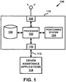
- FIG 1 is a block diagram of map-enhanced ADAS architecture 100.
- the map-enhanced ADAS architecture 100 includes driver assistance applications 114, and a map and positioning engine (MPE) 116.
- the MPE 116 is shown in Figure 1 as a standalone module; however, it is understood that the MPE 116 may be distributed into multiple packages and/or integrated into other device packages, such as a sensor package.
- the MPE 116 includes a processor 102, a positioning system 104, a geographic database 106, a communication system 108, and an in-vehicle data bus interface 110.
- the MPE 116 may also include other hardware, software, and/or firmware, such as memory and a power source.
- the processor 102 may be any type of processor, controller, or other computing device.
- the processor 102 may be a digital signal processor.
- the processor 102 receives inputs from the positioning system 104, the geographic database 106, the communication system 108, the in-vehicle data bus interface 110, and other sources.
- the processor 102 then processes the inputs using application software programs 200, some of which are described with reference to Figure 2 .
- the processor 102 then provides outputs to driver assistance applications 114 via the in-vehicle data bus interface 110 and a data bus 112.
- the in-vehicle data bus interface 110 and the data bus 112 are a Controller-Area Network (CAN) interface and a CAN-bus, which are designed for automotive applications.
- the driver assistance applications 114 may include adaptive headlight aiming, adaptive cruise control, obstruction detection, obstruction avoidance, collision avoidance, adaptive shift control, and others.
- the positioning system 104 may utilize GPS-type technology, a dead reckoning-type system, or combinations of these or other systems, all of which are known in the art.
- the positioning system 104 may also include suitable sensing devices that measure the traveling distance speed, direction, orientation, and so on.
- the positioning system 104 may include a GPS system and a gyroscope.
- the positioning system 104 provides an output signal to the processor 102.
- Some of the application software programs 200 that run on the processor 102 use the output signal from the positioning system 104 to determine the location, direction, orientation, etc., of the MPE 116.
- the geographic database 106 is designed for ADAS applications. Like a navigation system geographic database, the geographic database 106 contains data about roads and intersections in a geographic region. For example, the geographic database 106 contains at least one database record (also referred to as "entity” or “entry”) for each road segment.
- the road segment data record includes a segment identification (ID) by which the data record can be identified in the geographic database 106.
- the road segment data record also includes data providing the geographic coordinates (e.g., the latitude, longitude, altitude) of the endpoints of the represented road segment and data providing the shape of the road segment.
- the endpoint data references node data records that represent the nodes corresponding to the endpoints of the represented road segment.
- the node data records includes a node ID by which the data record can be identified in the geographic database 106.
- the geographic database 106 may include higher quality (i.e., more accurate) data than the data typically contained in a navigation system geographic database. For example, with respect to road geometry, the data in the geographic database 106 may be more accurate with respect to longitude, latitude, and/or altitude. Also, the starting and stopping locations of tunnels may be more accurately specified in the geographic database 106. Further, the data in the geographic database 106 may be more accurate with respect to derived information, such as curvature.
- the geographic database 106 may also include more kinds of data (e.g., more kinds of attributes) than the data typically contained in a navigation system geographic database.
- the geographic database 106 may include data about road objects, such as signs and crosswalks, including their positions along a road segment, sign object type, and sign text.
- the geographic database 106 is organized into parcels.
- a parcel is a grouping of one or more tiles, which are described with reference to Figure 4 .
- a parcel is the smallest unit of the geographic database 106 that can be replaced or updated.
- the geographic database 106 may be updated on a regular basis using the communications system 108.
- a portion of the geographic database 106 may be updated independently of other portions.
- the geographic database 106 may be updated by receiving new parcels that either add additional coverage to the geographic database 106 or replace existing parcels via the communications system 108.
- the communications system 108 preferably receives the new parcels over a wireless communications link. Any wireless communications system, including cellular, PCS, satellite, FM, radio, or technologies that may be developed in the future, may be used to transmit the new or updated parcels to the communications system 108.
- Figure 2 is a block diagram depicting some of the software applications 200 available to the processor 102.
- the software applications 200 depicted in Figure 2 include a map access application 202, a map update application 204, a vehicle positioning application 206, an electronic horizon application 208, and an interface application 210.
- Figure 2 also depicts other applications 212, which may include a startup routine, self-test diagnostics, and so on.
- the map access application 202 provides data access to the geographic database 106 stored on physical storage media.
- the map access application 202 receives a request for data from the processor 102 and locates data responsive to the request on the physical storage media. As described with respect to Figures 6-7 , the map access application 202 uses a spatial index to identify and read the requested data.
- the map access application 202 preferably provides an application programming interface (API) for use by the processor 102 and/or other applications 200.
- API application programming interface
- the map update application 204 facilitates updates to the geographic database 106.
- the communications system 108 receives one or more parcels that either add additional coverage to an existing database or replace existing parcels.
- the map update application 204 stores the parcel on the physical storage media.
- the map update application 204 replaces the old parcel with the new parcel on the physical storage media.
- the vehicle positioning application 206 determines the vehicle's position relative to a road network that is represented by data included in the geographic database 106.
- the vehicle positioning application 206 uses the output from the positioning system 104 and matches the output to data in the geographic database 106 using a vehicle positioning algorithm, which is sometimes referred to as a map matching algorithm.
- the vehicle positioning application 206 may use any vehicle positioning algorithm currently known or developed in the future.
- the electronic horizon application 208 determines an electronic horizon.
- An electronic horizon is a collection of roads and intersections leading out from the current vehicle position to an extent determined by the electronic horizon application 208.
- the collection of roads and intersections are potential paths that the vehicle may follow from the current vehicle position.
- the electronic horizon application 208 determines extent using one or more costing functions.
- the costing functions are based on the needs of the driver assistance applications 114 and may take into consideration various factors, such as vehicle speed, travel time, and driving distance.
- An example electronic horizon application is described in U.S. Patent No. 6,405,128 , which is assigned to the same assignee as the current application and is hereby incorporated by reference in its entirety.
- the interface application 210 controls communications between the MPE 116 and the driver assistance applications 114 via the interface 110 and the bus 112.
- the interface application 210 is based on the CAN protocol, which is a serial communication protocol for communicating between various electronic devices in the vehicle.
- the various electronic devices in the vehicle can be coupled to a single serial bus (e.g., the bus 112) such that messages and data can be sent from one electronic device in the vehicle to another.
- the CAN protocol is a message based protocol in which CAN frames are placed on a common CAN bus.
- the CAN bus may be a single wire or may be a differentially driven pair of wires.
- Figure 3 is a block diagram of some of the data attributes 300 for road segment data records found in the geographic database 106.
- the data attributes depicted in Figure 3 include segment identification 302, control points 304, direction of travel 306, speed category 308, lane category 310, road type 312, segment characteristics 314, and access characteristics 316.
- Figure 3 also depicts other attributes 318.
- the segment data attributes 300 may also include references to node data records in the form of a node ID corresponding to endpoints of the segment.
- the road segment data record includes a segment ID 302 by which the data record can be identified in the geographic database 106.
- the control point attributes 304 contain bit flags that provide additional information regarding control points to aid in the creation of curvature, heading, and slope profiles from spline data.
- the control point attributes 304 may include a byte-size flag per control point. One of the bits in the flag is assigned to curvature, while another of the bits is assigned to slope. If the curvature bit flag is set to one, then the control point is marked as part of the curvature profile. Similarly, if the slope bit flag is set to one, then the control point is marked as part of the slope profile.
- the direction of travel attribute 306 represents the allowed direction of traffic flow on a segment.
- the segment may represent a portion of a road network in which travel is permitted in both directions.
- the segment may represent a portion of a road network allowing only one-way travel.
- the direction of travel attribute 306 identifies whether the segment allows bi-directional travel or unidirectional travel, and if unidirectional, the direction of travel attribute 306 also identifies the allowed direction of travel.
- the speed category attribute 308 represents the general speed trend of a road based on posted or implied speed limit.
- the speed category attribute 308 contains data associated with a speed range.
- the speed category attribute 308 may include a data representation of the integer 1 for speeds exceeding 80 mph, the integer 2 for speeds in the range of 65-80mph, the integer 3 for speeds in the range of 55-64 mph, and so on until the speed range includes 0 mph.
- the lane category attribute 310 represents the predominant number of lanes on a segment in one direction of travel. Preferably, the lane category attribute 310 does not include turn lanes. If the number of lanes is different for each direction, the lane category attribute 310 may represent the higher number.
- the road type attribute 312 represents the type of road the segment represents.
- the road type attribute 312 may contain data associated with an interstate highway, a controlled access highway, a ramp, a pedestrian walkway, and so on.
- the segment characteristic attribute 314 contains bit flags that describe various characteristics of the segment. For example, the segment characteristic attribute 314 may identify whether a segment is paved, a ramp, a bridge, a tunnel, a roundabout, and so on.
- the access characteristic attribute 316 contains bit flags that define the types of traffic allowed on the segment. For example, the access characteristic attribute 316 may identify whether cars, buses, trucks, taxis, emergency vehicles, pedestrians, and so on are allowed on the segment.
- Figure 4 depicts a world map 400 segmented into tiles 402.
- the tiles are bounded by lines of constant latitude or longitude.
- the size in longitude and latitude direction is preferably equal in terms of World Geodetic System 1984 (WGS 84) coordinate units.
- WGS 84 coordinate system uniquely identifies every point (x, y; where x corresponds to longitude and y corresponds to latitude) on the earth's surface except the North and South Poles.
- the world tile grid 400 consists of 8,192 (2 13 ) rows and 16,384 (2 14 ) columns with row 0 located at -90 degrees latitude and column 0 located at -180 degrees longitude.
- Each of the tiles 402 is assigned a tile ID.
- the tile ID is a sequential number starting from zero, in row order, west to east, then south to north.
- the area coverage per tile 402 depends on the latitude.
- Each of the tiles 402 has a height of approximately 2.44 km.
- the width of the tile 402 varies based on the latitude and ranges from approximately 2.44 km at the equator down to approximately 424 meters at ⁇ 80 degrees latitude.
- tile borderlines are assigned to tiles.
- each of the tiles 402 contains its western and southern borderline, while the eastern and northern border lines are part of a neighboring tile.
- (x 1 , y 1 ) is the southwest corner of a tile and (x 2 , y 2 ) is the tile's northeast corner, then all points (x, y) with x 1 ⁇ x ⁇ x 2 and y 1 ⁇ y ⁇ y 2 are uniquely assigned to that tile.
- other mechanisms for assigning borderlines may also be used.
- FIG. 5 is a block diagram shows how the tiles 402 depicted in Figure 4 are grouped into parcels 500 (denoted by the darker lines).
- the geographic database 106 is organized as a collection of parcels 500, each of which contains the data for one or more tiles 402.
- the data in the geographic database 106 is stored on the physical storage media by parcel.
- the parcels 500 can be spatial parcels, representing map data for a single geographic area, including position coordinates.
- the parcels 500 can also be non-spatial, representing a particular type of data (e.g., an index).
- Each parcel 500 begins with a header specifying the type and size of the parcel, and any parameters specific to that parcel.
- Parcelization is the process of dividing the geographic database 106 into spatial parcels.
- the parcel boundaries are defined based on the world tile grid 400 described with respect to Figure 4 .
- the parcel 500 can be defined as a single tile 402 or a rectangular group (including square groups) of tiles 402.
- the number of tiles 402 contained in the parcel 500 is determined by a compiler based on a target parcel size. For example, Figure 5 depicts twenty-eight tiles 402 grouped into eight parcels 500 of various sizes.
- the parcels are stored on the physical storage media.
- the physical storage media is flash memory; however, any suitable memory type may be used to store the geographic database 106.
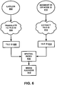
- Figure 6 is a flow chart depicting how a spatial index 616 is used to locate the parcels 500 on the physical storage media.
- the spatial index 616 locates a spatial parcel 500 on the physical storage media using a tile ID 608, 614.
- the spatial index 616 receives the tile ID 608, 614 after the map access application 202 receives a request for geographic data from the processor 102.
- the request for geographic data may include data regarding the vehicle's current location.
- the data regarding the vehicle's current location may be in the form of geographic coordinates 602 (i.e., latitude/longitude) of the vehicle's position based on data from the positioning system 104.
- the data regarding the vehicle's current location may be in the form of a segment ID and/or a node ID 610 currently associated with the vehicle's position based on data from the vehicle positioning application 206.
- the request for geographic data may include a segment ID and/or a node ID 610 without reference to the vehicle's current position.
- the map access application 202 If the map access application 202 receives the segment ID and/or node ID 610, the map access application 202 extracts 612 the tile ID 614.
- the tile ID 614 is embedded in the geographic database ID.
- the map access application 202 uses the segment ID and/or the node ID 610 to obtain the tile ID 614 from the geographic database ID.
- the map access application 202 identifies the parcel's media address 618 using the spatial index 616.
- Each entry in the spatial index 616 is the media address 618 of the parcel 500 containing the corresponding tile 402.
- the spatial index 616 uses the tile ID, rather than a parcel ID, to obtain the media address 618.
- Using the tile ID allows the spatial index 616 to be a two-dimensional array indexed by a tile's row and column in the world tile grid 400.
- the spatial index 616 design is simpler than an index using parcel IDs, which is typically a tree index (e.g., a kd-tree index).
- the media address 618 is used to access and read the parcel 500 from the physical storage media.
- the media address 618 includes a Media Table of Contents (MTOC) index, a parcel offset (e.g., in sectors) from the address specified in the MTOC for that entry, and a parcel size (e.g., in sectors).
- MTOC Media Table of Contents
- Various types of physical storage media have different logical sector sizes. Typically, one logical sector is the smallest amount of data that can be read.
- the MTOC index identifies and locates components contained in the geographic database 106.
- the MTOC index is used to access an appropriate MTOC entry (e.g., component type, offset from beginning of file, size of component, and component filename).
- the information in the MTOC combined with a parcel offset in the media address 618 may be used to read the parcel 500 from the physical storage media. Because the media address 618 is relative to an entry in the MTOC, the order of parcels on the physical storage media can be changed and new parcels can be added without affecting existing software.
- FIG 7 is a block diagram of the spatial index 616 depicted in Figure 6 .
- the spatial index 616 is organized as a sparse two dimensional array indexed by the tile's row and column numbers. As described above, because the spatial index 616 uses the tile ID and not the parcel ID, the spatial index 616 does not need to use a more complicated tree index. However, unlike parcels, which are typically uniformly filled, the tiles 402 are not uniformly filled and many tiles contain no geographic data at all (e.g., oceans, farm fields, rural areas). To reduce the amount of space needed to store the spatial index 616 on the physical storage media, the spatial index 616 is designed as a sparse array.
- a sparse array is an array in which most of the elements have the same value referred to as the default value, which is typically "0" or null.
- the spatial index 616 consists of a single row parcel 702 followed by one or more column parcels 704.
- the spatial index 616 may consist of a single column parcel followed by one or more row parcels.
- a single row parcel and/or a single column parcel may be stored in multiple parcels, for example, due to size constraints.
- multiple row and/or column indexes may be stored in a single parcel.
- the geographic database 106 has a database header 706 that contains information and parameters that describe the database 106.
- the database header 706 includes the media address of the spatial index's row parcel 702.
- Each spatial index parcel 702, 704 contains a spatial index parcel header 708, followed by an array of bit flags 710 that indicate the presence of a media address entry, followed by an array of media addresses 712.
- the spatial index parcel header 708 includes the type of spatial index parcel (i.e., row or column), the starting and ending index values for entries in the row or column, the number of bitmap fields in the array of bit flags 710, the number of media address entries in the array of media addresses 712, and offset values from the start of the header 708 to the arrays 710, 712.
- the spatial index parcel header 708 may include additional information as well.
- the array of bit flags 710 includes a series of bitmap fields that indicate the presence or absence of a media address entry in the array of media addresses 712.
- each of the bitmap fields is four bytes.
- the most significant bit of the first bitmap field corresponds to the starting index value specified in the spatial index parcel header 708.
- the remaining bits in the bitmap fields represent the corresponding media address entries in sequential order through the end index value specified in the spatial index parcel header 708.
- the spatial index 616 After identifying the row entry for the tile corresponding to the tile ID in the media address array 712 of the row parcel 702, the spatial index 616 identifies the media address of the spatial index's column parcel 704. After identifying the column entry for the tile corresponding to the tile ID in the media address array 712 of the column parcel 704, the spatial index 616 identifies the media address 618 of the parcel 500 containing the tile 402 corresponding to the tile ID 608, 614.
- the index of an entry in the media address array 712 that corresponds to a requested row or column index is the sum of the non-zero bits in the array of bit flags 710 that precede the bit for the requested index (requested index - start index).
- Figure 7 depicts one example configuration of the spatial index 616, it is understood that other sparse array designs may be used.
- a sparse array By using a sparse array, the amount of space needed to store the spatial index 616 on the physical storage media is reduced. Additionally, retrieval of data needed by an advanced driver assistance system from the physical storage media is more efficient.
Description
- The present invention relates generally to geographic databases for advanced driver assistance systems (ADAS), and more particularly, relates to locating geographic data parcels stored on a physical storage media for use by the advanced driver assistance systems.
- ADAS was developed to improve the comfort, efficiency, safety, and overall satisfaction of driving. Examples of these advanced driver assistance systems include adaptive headlight aiming, adaptive cruise control, lane departure warning and control, curve warning, speed limit notification, hazard warning, predictive cruise control, and adaptive shift control, as well as others. Some of these advanced driver assistance systems use a variety of sensor mechanisms in the vehicle to determine the current state of the vehicle and the current state of the roadway in front of the vehicle. These sensor mechanisms may include radar, infrared, ultrasonic, and vision-oriented sensors, such as digital video cameras and lidar.
- Some advanced driver assistance systems also use digital map data. These systems are sometimes referred to as map-enhanced ADAS. Digital map data can be used in advanced driver assistance systems to provide information about the road network, road geometry, road conditions, and other items associated with the road and terrain around the vehicle. Unlike some sensors, digital map data is not affected by environmental conditions, such as fog, rain, or snow. In addition, digital map data can provide useful information that cannot reliably be provided by cameras or radar, such as curvature, grade, bank, speed limits that are not indicated by signage, traffic and lane restrictions, and so on. Further, digital map data can provide a predictive capability well beyond the range of other sensors or even beyond the driver's vision to determine the road ahead of the vehicle, around corners, over hills, or beyond obstructions. Accordingly, digital map data can be a useful addition for some advanced driver assistance systems.
- The map-enhanced advanced driver assistance systems commonly use data from a geographic database associated with a navigation system in a vehicle. The navigation system database contains data that represents the road network in the region, such as the locations (geographic coordinates, including altitude) of roads and intersections, road names, speed limits along roads, turn restrictions at intersections, addresses or address ranges along roads, the number of lanes each road has, lane width, lane markings, functional classes of roads, the locations of medians, and so on. The navigation system database may also contain information about other geographic features, such as bodies of water, parks, administrative areas (including municipal, state and country boundaries), and locations of points of interest, such as businesses, hospitals, police stations, and so on.
- The navigation system database has much more data than an advanced driver assistance system needs. Additionally, a geographic database designed for navigation may not have all the data and/or may not have data with the accuracy levels needed by an advanced driver assistance system. As a result, there has been some effort in designing a geographic database specifically for advanced driver assistance systems. For example,
U.S. Patent Publication No. 2006/0100780 describes a geographic database having a data storage format designed for a sensor device in a motor vehicle system. - Because a geographic database designed specifically for ADAS contains less data than a navigation system database, less memory is needed to store the ADAS database. For example, instead of storing the geographic database on a CD, the database can be stored on a memory chip. Other efficiencies may also be realized. For example, the manner in which data needed by an advanced driver assistance system is retrieved from physical storage media may be changed to improve the efficiency of data retrieval.
- According to an aspect of the invention, there is provided a system according to claim 1. According to another aspect of the invention, there is provided a method according to claim 8. Further aspects are defined by the dependent claims.
- In one example, a method and system for locating geographic data stored in parcels on physical storage media is disclosed. The geographic data is located in a geographic database that is organized by parcels of one or more tiles bounded by lines of constant latitude or longitude in a world tile grid. Each tile is assigned a tile ID. A map access application receives a request for geographic data. The request includes information that the map access application can use to obtain the tile ID for the tile associated with the requested geographic data. The information may be geographic coordinates of a current vehicle position as determined by a positioning system. The information may also be a segment or node identification.
- After obtaining the tile ID, the map access application identifies a row and a column associated with the tile and uses a spatial index organized as a sparse two dimensional array to identify a media address of the parcel that contains the requested data. The map access application uses the media address to access and read the parcel from the physical storage media. The map access application then provides access to the parcel of geographic data so that the driver assistance application can receive the geographic data.
- These as well as other aspects and advantages will become apparent to those of ordinary skill in the art by reading the following detailed description, with reference where appropriate to the accompanying drawings. Further, it is understood that this summary is merely an example and is not intended to limit the scope of the invention as claimed.
- Presently preferred embodiments are described below in conjunction with the appended drawing figures, wherein like reference numerals refer to like elements in the various figures, and wherein:
-
Figure 1 is a block diagram of map-enhanced ADAS architecture, according to an example; -
Figure 2 is a block diagram of software applications available to a processor depicted inFigure 1 , according to an example; -
Figure 3 is a block diagram of data attributes for road segment data records in a geographical database depicted inFigure 1 , according to an example; -
Figure 4 is a diagram depicting a world map segmented into tiles, according to an example; -
Figure 5 is a block diagram showing how the tiles depicted inFigure 5 are parcelized, according to an example; -
Figure 6 is a flow chart showing how a spatial index is used to locate the parcels depicted inFigure 5 on physical storage media, according to an example; and -
Figure 7 is a block diagram of the spatial index depicted inFigure 6 , according to an example. -
Figure 1 is a block diagram of map-enhanced ADASarchitecture 100. In this example, the map-enhanced ADASarchitecture 100 includesdriver assistance applications 114, and a map and positioning engine (MPE) 116. The MPE 116 is shown inFigure 1 as a standalone module; however, it is understood that the MPE 116 may be distributed into multiple packages and/or integrated into other device packages, such as a sensor package. The MPE 116 includes aprocessor 102, apositioning system 104, ageographic database 106, acommunication system 108, and an in-vehicledata bus interface 110. The MPE 116 may also include other hardware, software, and/or firmware, such as memory and a power source. - The
processor 102 may be any type of processor, controller, or other computing device. For example, theprocessor 102 may be a digital signal processor. Theprocessor 102 receives inputs from thepositioning system 104, thegeographic database 106, thecommunication system 108, the in-vehicledata bus interface 110, and other sources. Theprocessor 102 then processes the inputs usingapplication software programs 200, some of which are described with reference toFigure 2 . - The
processor 102 then provides outputs todriver assistance applications 114 via the in-vehicledata bus interface 110 and adata bus 112. Preferably, the in-vehicledata bus interface 110 and thedata bus 112 are a Controller-Area Network (CAN) interface and a CAN-bus, which are designed for automotive applications. Thedriver assistance applications 114 may include adaptive headlight aiming, adaptive cruise control, obstruction detection, obstruction avoidance, collision avoidance, adaptive shift control, and others. - The
positioning system 104 may utilize GPS-type technology, a dead reckoning-type system, or combinations of these or other systems, all of which are known in the art. Thepositioning system 104 may also include suitable sensing devices that measure the traveling distance speed, direction, orientation, and so on. For example, thepositioning system 104 may include a GPS system and a gyroscope. Thepositioning system 104 provides an output signal to theprocessor 102. Some of theapplication software programs 200 that run on theprocessor 102 use the output signal from thepositioning system 104 to determine the location, direction, orientation, etc., of theMPE 116. - The
geographic database 106 is designed for ADAS applications. Like a navigation system geographic database, thegeographic database 106 contains data about roads and intersections in a geographic region. For example, thegeographic database 106 contains at least one database record (also referred to as "entity" or "entry") for each road segment. The road segment data record includes a segment identification (ID) by which the data record can be identified in thegeographic database 106. - The road segment data record also includes data providing the geographic coordinates (e.g., the latitude, longitude, altitude) of the endpoints of the represented road segment and data providing the shape of the road segment. In one embodiment, the endpoint data references node data records that represent the nodes corresponding to the endpoints of the represented road segment. Like the segment ID, the node data records includes a node ID by which the data record can be identified in the
geographic database 106. - The
geographic database 106 may include higher quality (i.e., more accurate) data than the data typically contained in a navigation system geographic database. For example, with respect to road geometry, the data in thegeographic database 106 may be more accurate with respect to longitude, latitude, and/or altitude. Also, the starting and stopping locations of tunnels may be more accurately specified in thegeographic database 106. Further, the data in thegeographic database 106 may be more accurate with respect to derived information, such as curvature. - The
geographic database 106 may also include more kinds of data (e.g., more kinds of attributes) than the data typically contained in a navigation system geographic database. For example, thegeographic database 106 may include data about road objects, such as signs and crosswalks, including their positions along a road segment, sign object type, and sign text. Some of the data attributes found in thegeographic database 106 are described with reference toFigure 3 . - The
geographic database 106 is organized into parcels. A parcel is a grouping of one or more tiles, which are described with reference toFigure 4 . A parcel is the smallest unit of thegeographic database 106 that can be replaced or updated. Thegeographic database 106 may be updated on a regular basis using thecommunications system 108. A portion of thegeographic database 106 may be updated independently of other portions. Thegeographic database 106 may be updated by receiving new parcels that either add additional coverage to thegeographic database 106 or replace existing parcels via thecommunications system 108. Thecommunications system 108 preferably receives the new parcels over a wireless communications link. Any wireless communications system, including cellular, PCS, satellite, FM, radio, or technologies that may be developed in the future, may be used to transmit the new or updated parcels to thecommunications system 108. -
Figure 2 is a block diagram depicting some of thesoftware applications 200 available to theprocessor 102. Thesoftware applications 200 depicted inFigure 2 , include a map access application 202, amap update application 204, a vehicle positioning application 206, an electronic horizon application 208, and aninterface application 210. As this is not an exhaustive list of all thesoftware applications 200 available to theprocessor 102,Figure 2 also depictsother applications 212, which may include a startup routine, self-test diagnostics, and so on. - The map access application 202 provides data access to the
geographic database 106 stored on physical storage media. The map access application 202 receives a request for data from theprocessor 102 and locates data responsive to the request on the physical storage media. As described with respect toFigures 6-7 , the map access application 202 uses a spatial index to identify and read the requested data. The map access application 202 preferably provides an application programming interface (API) for use by theprocessor 102 and/orother applications 200. - The
map update application 204 facilitates updates to thegeographic database 106. Thecommunications system 108 receives one or more parcels that either add additional coverage to an existing database or replace existing parcels. For new parcels, themap update application 204 stores the parcel on the physical storage media. For existing parcels, themap update application 204 replaces the old parcel with the new parcel on the physical storage media. - The vehicle positioning application 206 determines the vehicle's position relative to a road network that is represented by data included in the
geographic database 106. The vehicle positioning application 206 uses the output from thepositioning system 104 and matches the output to data in thegeographic database 106 using a vehicle positioning algorithm, which is sometimes referred to as a map matching algorithm. The vehicle positioning application 206 may use any vehicle positioning algorithm currently known or developed in the future. - The electronic horizon application 208 determines an electronic horizon. An electronic horizon is a collection of roads and intersections leading out from the current vehicle position to an extent determined by the electronic horizon application 208. The collection of roads and intersections are potential paths that the vehicle may follow from the current vehicle position. The electronic horizon application 208 determines extent using one or more costing functions. The costing functions are based on the needs of the
driver assistance applications 114 and may take into consideration various factors, such as vehicle speed, travel time, and driving distance. An example electronic horizon application is described inU.S. Patent No. 6,405,128 , which is assigned to the same assignee as the current application and is hereby incorporated by reference in its entirety. - The
interface application 210 controls communications between theMPE 116 and thedriver assistance applications 114 via theinterface 110 and thebus 112. Preferably, theinterface application 210 is based on the CAN protocol, which is a serial communication protocol for communicating between various electronic devices in the vehicle. In accordance with the CAN protocol, the various electronic devices in the vehicle can be coupled to a single serial bus (e.g., the bus 112) such that messages and data can be sent from one electronic device in the vehicle to another. The CAN protocol is a message based protocol in which CAN frames are placed on a common CAN bus. The CAN bus may be a single wire or may be a differentially driven pair of wires. -
Figure 3 is a block diagram of some of the data attributes 300 for road segment data records found in thegeographic database 106. The data attributes depicted inFigure 3 includesegment identification 302, control points 304, direction oftravel 306,speed category 308,lane category 310,road type 312,segment characteristics 314, andaccess characteristics 316. As this is not an exhaustive list of all the data attributes for the road segment data records,Figure 3 also depicts other attributes 318. For example, the segment data attributes 300 may also include references to node data records in the form of a node ID corresponding to endpoints of the segment. - As described previously, the road segment data record includes a
segment ID 302 by which the data record can be identified in thegeographic database 106. The control point attributes 304 contain bit flags that provide additional information regarding control points to aid in the creation of curvature, heading, and slope profiles from spline data. For example, the control point attributes 304 may include a byte-size flag per control point. One of the bits in the flag is assigned to curvature, while another of the bits is assigned to slope. If the curvature bit flag is set to one, then the control point is marked as part of the curvature profile. Similarly, if the slope bit flag is set to one, then the control point is marked as part of the slope profile. - The direction of
travel attribute 306 represents the allowed direction of traffic flow on a segment. For example, the segment may represent a portion of a road network in which travel is permitted in both directions. Alternatively, the segment may represent a portion of a road network allowing only one-way travel. The direction oftravel attribute 306 identifies whether the segment allows bi-directional travel or unidirectional travel, and if unidirectional, the direction oftravel attribute 306 also identifies the allowed direction of travel. - The
speed category attribute 308 represents the general speed trend of a road based on posted or implied speed limit. Thespeed category attribute 308 contains data associated with a speed range. For example, thespeed category attribute 308 may include a data representation of the integer 1 for speeds exceeding 80 mph, the integer 2 for speeds in the range of 65-80mph, the integer 3 for speeds in the range of 55-64 mph, and so on until the speed range includes 0 mph. - The
lane category attribute 310 represents the predominant number of lanes on a segment in one direction of travel. Preferably, thelane category attribute 310 does not include turn lanes. If the number of lanes is different for each direction, thelane category attribute 310 may represent the higher number. - The
road type attribute 312 represents the type of road the segment represents. For example, theroad type attribute 312 may contain data associated with an interstate highway, a controlled access highway, a ramp, a pedestrian walkway, and so on. - The segment
characteristic attribute 314 contains bit flags that describe various characteristics of the segment. For example, the segmentcharacteristic attribute 314 may identify whether a segment is paved, a ramp, a bridge, a tunnel, a roundabout, and so on. - The access
characteristic attribute 316 contains bit flags that define the types of traffic allowed on the segment. For example, the accesscharacteristic attribute 316 may identify whether cars, buses, trucks, taxis, emergency vehicles, pedestrians, and so on are allowed on the segment. -
Figure 4 depicts aworld map 400 segmented intotiles 402. The tiles are bounded by lines of constant latitude or longitude. The size in longitude and latitude direction is preferably equal in terms of World Geodetic System 1984 (WGS 84) coordinate units. However, other coordinate systems for the earth now known or developed in the future may be used. Beneficially, the WGS 84 coordinate system uniquely identifies every point (x, y; where x corresponds to longitude and y corresponds to latitude) on the earth's surface except the North and South Poles. - The
world tile grid 400 consists of 8,192 (213) rows and 16,384 (214) columns with row 0 located at -90 degrees latitude and column 0 located at -180 degrees longitude. Each of thetiles 402 is assigned a tile ID. Preferably, the tile ID is a sequential number starting from zero, in row order, west to east, then south to north. - With WGS 84, the area coverage per
tile 402 depends on the latitude. Each of thetiles 402 has a height of approximately 2.44 km. The width of thetile 402 varies based on the latitude and ranges from approximately 2.44 km at the equator down to approximately 424 meters at ±80 degrees latitude. - In order to provide a unique allocation of coordinates to the
tiles 402, tile borderlines are assigned to tiles. In one example, each of thetiles 402 contains its western and southern borderline, while the eastern and northern border lines are part of a neighboring tile. Thus, if (x1, y1) is the southwest corner of a tile and (x2, y2) is the tile's northeast corner, then all points (x, y) with x1 ≤ x < x2 and y1 ≤ y < y2 are uniquely assigned to that tile. Of course, other mechanisms for assigning borderlines may also be used. -
Figure 5 is a block diagram shows how thetiles 402 depicted inFigure 4 are grouped into parcels 500 (denoted by the darker lines). Thegeographic database 106 is organized as a collection ofparcels 500, each of which contains the data for one ormore tiles 402. The data in thegeographic database 106 is stored on the physical storage media by parcel. Theparcels 500 can be spatial parcels, representing map data for a single geographic area, including position coordinates. Theparcels 500 can also be non-spatial, representing a particular type of data (e.g., an index). Eachparcel 500 begins with a header specifying the type and size of the parcel, and any parameters specific to that parcel. - Parcelization is the process of dividing the
geographic database 106 into spatial parcels. The parcel boundaries are defined based on theworld tile grid 400 described with respect toFigure 4 . Theparcel 500 can be defined as asingle tile 402 or a rectangular group (including square groups) oftiles 402. The number oftiles 402 contained in theparcel 500 is determined by a compiler based on a target parcel size. For example,Figure 5 depicts twenty-eighttiles 402 grouped into eightparcels 500 of various sizes. After parcelization, the parcels are stored on the physical storage media. Preferably, the physical storage media is flash memory; however, any suitable memory type may be used to store thegeographic database 106. -
Figure 6 is a flow chart depicting how aspatial index 616 is used to locate theparcels 500 on the physical storage media. Thespatial index 616 locates aspatial parcel 500 on the physical storage media using atile ID spatial index 616 receives thetile ID processor 102. - The request for geographic data may include data regarding the vehicle's current location. The data regarding the vehicle's current location may be in the form of geographic coordinates 602 (i.e., latitude/longitude) of the vehicle's position based on data from the
positioning system 104. Alternatively, the data regarding the vehicle's current location may be in the form of a segment ID and/or anode ID 610 currently associated with the vehicle's position based on data from the vehicle positioning application 206. Alternatively, the request for geographic data may include a segment ID and/or anode ID 610 without reference to the vehicle's current position. - If the map access application 202 receives the
geographic coordinates 602 of the vehicle, the map access application 202 translates 604 thegeographic coordinates 602 into thetile ID 608. For example, the map access application 202 may compute thetile ID 608 from the latitude and longitude as follows:


- If the map access application 202 receives the segment ID and/or
node ID 610, the map access application 202extracts 612 thetile ID 614. Thetile ID 614 is embedded in the geographic database ID. The map access application 202 uses the segment ID and/or thenode ID 610 to obtain thetile ID 614 from the geographic database ID. - Once the
tile ID translation 604 orextraction 612, the map access application 202 identifies the parcel'smedia address 618 using thespatial index 616. Each entry in thespatial index 616 is themedia address 618 of theparcel 500 containing thecorresponding tile 402. The row and column number of thetile 402 can be obtained from thetile ID 

- Beneficially, the
spatial index 616 uses the tile ID, rather than a parcel ID, to obtain themedia address 618. Using the tile ID allows thespatial index 616 to be a two-dimensional array indexed by a tile's row and column in theworld tile grid 400. As a result, thespatial index 616 design is simpler than an index using parcel IDs, which is typically a tree index (e.g., a kd-tree index). - The
media address 618 is used to access and read theparcel 500 from the physical storage media. In one example, themedia address 618 includes a Media Table of Contents (MTOC) index, a parcel offset (e.g., in sectors) from the address specified in the MTOC for that entry, and a parcel size (e.g., in sectors). Various types of physical storage media have different logical sector sizes. Typically, one logical sector is the smallest amount of data that can be read. - The MTOC index identifies and locates components contained in the
geographic database 106. The MTOC index is used to access an appropriate MTOC entry (e.g., component type, offset from beginning of file, size of component, and component filename). The information in the MTOC combined with a parcel offset in themedia address 618 may be used to read theparcel 500 from the physical storage media. Because themedia address 618 is relative to an entry in the MTOC, the order of parcels on the physical storage media can be changed and new parcels can be added without affecting existing software. -
Figure 7 is a block diagram of thespatial index 616 depicted inFigure 6 . Thespatial index 616 is organized as a sparse two dimensional array indexed by the tile's row and column numbers. As described above, because thespatial index 616 uses the tile ID and not the parcel ID, thespatial index 616 does not need to use a more complicated tree index. However, unlike parcels, which are typically uniformly filled, thetiles 402 are not uniformly filled and many tiles contain no geographic data at all (e.g., oceans, farm fields, rural areas). To reduce the amount of space needed to store thespatial index 616 on the physical storage media, thespatial index 616 is designed as a sparse array. A sparse array is an array in which most of the elements have the same value referred to as the default value, which is typically "0" or null. - The
spatial index 616 consists of asingle row parcel 702 followed by one ormore column parcels 704. In another example, thespatial index 616 may consist of a single column parcel followed by one or more row parcels. In yet another example, a single row parcel and/or a single column parcel may be stored in multiple parcels, for example, due to size constraints. In yet another example, multiple row and/or column indexes may be stored in a single parcel. - The
geographic database 106 has a database header 706 that contains information and parameters that describe thedatabase 106. The database header 706 includes the media address of the spatial index'srow parcel 702. - Each
spatial index parcel index parcel header 708, followed by an array ofbit flags 710 that indicate the presence of a media address entry, followed by an array of media addresses 712. The spatialindex parcel header 708 includes the type of spatial index parcel (i.e., row or column), the starting and ending index values for entries in the row or column, the number of bitmap fields in the array ofbit flags 710, the number of media address entries in the array of media addresses 712, and offset values from the start of theheader 708 to thearrays index parcel header 708 may include additional information as well. - The array of bit flags 710 includes a series of bitmap fields that indicate the presence or absence of a media address entry in the array of media addresses 712. Preferably, each of the bitmap fields is four bytes. The most significant bit of the first bitmap field corresponds to the starting index value specified in the spatial
index parcel header 708. The remaining bits in the bitmap fields represent the corresponding media address entries in sequential order through the end index value specified in the spatialindex parcel header 708. - After identifying the row entry for the tile corresponding to the tile ID in the
media address array 712 of therow parcel 702, thespatial index 616 identifies the media address of the spatial index'scolumn parcel 704. After identifying the column entry for the tile corresponding to the tile ID in themedia address array 712 of thecolumn parcel 704, thespatial index 616 identifies themedia address 618 of theparcel 500 containing thetile 402 corresponding to thetile ID - The index of an entry in the
media address array 712 that corresponds to a requested row or column index is the sum of the non-zero bits in the array ofbit flags 710 that precede the bit for the requested index (requested index - start index). - While
Figure 7 depicts one example configuration of thespatial index 616, it is understood that other sparse array designs may be used. By using a sparse array, the amount of space needed to store thespatial index 616 on the physical storage media is reduced. Additionally, retrieval of data needed by an advanced driver assistance system from the physical storage media is more efficient. - It is intended that the foregoing detailed description be regarded as illustrative rather than limiting and that it is understood that the following claims including all equivalents are intended to define the scope of the invention. For example, while the
geographic database 106 was described as an ADAS database, other databases may also benefit from a spatial index that is organized as a sparse array to locate data on a physical storage media. The claims should not be read as limited to the described order or elements unless stated to that effect. Therefore, all embodiments that come within the scope and spirit of the following claims and equivalents thereto are claimed as the invention.
Claims (15)
- A system for locating geographic data sorted in parcels on physical storage media, wherein the geographic data is located in a geographic database that is organized by parcels of one or more tiles bounded by lines of constant latitude or constant longitude in a world tile grid segmenting a world map into tiles of constant latitude or constant longitude, wherein the geographic database is organized as a collection of parcels such that the data in the geographic database is stored on the physical storage media by parcel, wherein each parcel has a parcel boundary defined based on the world tile grid, and wherein each parcel contains the data for one or more tiles in the world tile grid,
the system comprising:a software application configured to receive a request for geographic data, wherein the request includes information that the software application uses to identify a tile in the world tile grid that contains the requested geographic data and to obtain a tile identification of this tile;a spatial index organized as a two-dimensional sparse array indexed by a tile's row and column in the world tile grid wherein each entry in the spatial index is a media address of the parcel containing the corresponding tile,wherein the software application is configured to provide the tile identification to the spatial index and the spatial index is configured to use the tile identification to identify a row and a column associated with the tile,and wherein the spatial index is configured to use the row and the column to identify a parcel location at the corresponding media address on the physical storage media that contains the requested geographic data contained in the corresponding required tile. - The system of claim 1, wherein the information that the software application uses to identify the tile includes data associated with a current position of a vehicle.
- The system of claim 2, wherein the data associated with the current position of the vehicle includes geographic coordinates of the vehicle's position.
- The system of claim 2, wherein the data associated with the current position of the vehicle includes at least one of a segment identification and a node identification.
- The system of claim 1, wherein the information that the software application uses to identify the tile includes at least one of a segment identification and a node identification.
- The system of claim 1, wherein the spatial index includes a single row parcel and at least one column parcel.
- The system of claim 6, wherein the row parcel and the at least one column parcel includes a header, a first array, and a second array, wherein the first array indicates presence of entries in the second array.
- A method for locating geographic data stored in parcels on physical storage media, the method being performed by a software application,
wherein the geographic data is located in a geographic database that is organized by parcels of one or more tiles bounded by lines of constant latitude or constant longitude in a world tile grid segmenting a world map into tiles of constant latitude or constant longitude, wherein the geographic database is organized as a collection of parcels such that the data in the geographic database is stored on the physical storage media by parcel, wherein each parcel has a parcel boundary defined based on the world tile grid, and wherein each parcel contains the data for one or more tiles in the world tile grid, the method comprising:receiving a request for geographic data, wherein the request includes information identifying a tile in the world tile grid that contains the requested geographic data;identifying a tile that contains the requested geographic data and obtaining a tile identification of this tile, wherein the tile identification is associated with the row and the column of the required tile in the world tile grid; andretrieving a media address for a parcel containing the corresponding tile using a spatial index organized as a two-dimensional sparse array indexed by the tile's row and column in the world tile grid, wherein the row and column associated with the required tile are obtained from the tile identification. - The method of claim 8, wherein the request includes data associated with a current position of a vehicle.
- The method of claim 9, wherein the data associated with the current position of the vehicle includes geographic coordinates of the vehicle's position.
- The method of claim 10, wherein identifying the tile includes translating the geographic coordinates of the vehicle's position to obtain the tile identification.
- The method of claim 9, wherein the data associated with the current position of the vehicle includes at least one of a segment identification and a node identification.
- The method of claim 12, wherein identifying the tile includes extracting the tile identification from a geographic database identification using at least one of the segment identification and the node identification.
- The method of claim 8, wherein the request includes at least one of a segment identification and a node identification.
- The method of claim 8, further comprising reading the parcel from the physical storage media.
Applications Claiming Priority (1)
| Application Number | Priority Date | Filing Date | Title |
|---|---|---|---|
| US12/243,186 US20100082564A1 (en) | 2008-10-01 | 2008-10-01 | Spatial Index for Locating Geographic Data Parcels Stored on Physical Storage Media |
Publications (2)
| Publication Number | Publication Date |
|---|---|
| EP2175385A1 EP2175385A1 (en) | 2010-04-14 |
| EP2175385B1 true EP2175385B1 (en) | 2019-11-13 |
Family
ID=41351755
Family Applications (1)
| Application Number | Title | Priority Date | Filing Date |
|---|---|---|---|
| EP09252211.9A Active EP2175385B1 (en) | 2008-10-01 | 2009-09-17 | Spatial index for locating geographic data parcels stored on physical storage media |
Country Status (3)
| Country | Link |
|---|---|
| US (1) | US20100082564A1 (en) |
| EP (1) | EP2175385B1 (en) |
| JP (3) | JP2010085414A (en) |
Families Citing this family (16)
| Publication number | Priority date | Publication date | Assignee | Title |
|---|---|---|---|---|
| US7972045B2 (en) * | 2006-08-11 | 2011-07-05 | Donnelly Corporation | Automatic headlamp control system |
| US20130066881A1 (en) * | 2009-05-15 | 2013-03-14 | Hyundai Motor Company | Indexing system of spatial information for combined soi object and content |
| US8023540B2 (en) * | 2009-05-26 | 2011-09-20 | Redfern Integrated Optics, Inc. | Pair of optically locked semiconductor narrow linewidth external cavity lasers with frequency offset tuning |
| US20100306287A1 (en) * | 2009-05-26 | 2010-12-02 | Nabil Raafat Mahrous Raphaeil | Method and apparatus for global addressing of parcels of land |
| CN101976239A (en) * | 2010-09-19 | 2011-02-16 | 北京腾瑞万里科技有限公司 | Method and device for searching geographical object information |
| US8676494B2 (en) * | 2010-09-29 | 2014-03-18 | Navteq B.V. | Multi-dimensional road representation |
| EP2518443B1 (en) * | 2011-04-29 | 2016-06-08 | Harman Becker Automotive Systems GmbH | Method of generating a database, navigation device and method of determining height information |
| CN103927933B (en) * | 2013-01-14 | 2016-07-13 | 北京中交兴路信息科技有限公司 | A kind of magnanimity moves method and the device that target renders |
| GB2513196A (en) * | 2013-04-19 | 2014-10-22 | What3Words Ltd | A method and apparatus for identifying and communicating locations |
| JP2015161717A (en) * | 2014-02-26 | 2015-09-07 | 株式会社デンソー | data structure of map data |
| US10007677B1 (en) | 2014-12-04 | 2018-06-26 | Google Llc | System and method for geospatial indexing |
| US10049129B2 (en) * | 2014-12-22 | 2018-08-14 | Here Global B.V. | Method and apparatus for providing map updates from distance based bucket processing |
| DE102015001247A1 (en) * | 2015-01-31 | 2016-08-04 | Audi Ag | Method for providing information about at least one object in a surrounding area of a motor vehicle and system |
| US9874450B2 (en) * | 2016-04-28 | 2018-01-23 | Here Global B.V. | Referencing closed area geometry |
| US10991241B2 (en) | 2016-07-20 | 2021-04-27 | Harman Becker Automotive Systems Gmbh | Dynamic layers for navigation database systems |
| CN115546493B (en) * | 2022-12-06 | 2023-05-02 | 成都智元汇信息技术股份有限公司 | Method, device and medium for filtering and weighing package identification information based on column data |
Family Cites Families (31)
| Publication number | Priority date | Publication date | Assignee | Title |
|---|---|---|---|---|
| NL8602654A (en) * | 1986-10-23 | 1988-05-16 | Philips Nv | METHOD FOR DIVIDING IN LOTS AND STORING BITCH IN A MASSAGE MEMORY A DATA FILE, AND FOR ADDRESSING A LOT, AND APPARATUS FOR PERFORMING THE METHOD |
| US5408663A (en) * | 1993-11-05 | 1995-04-18 | Adrem Technologies, Inc. | Resource allocation methods |
| US6321158B1 (en) * | 1994-06-24 | 2001-11-20 | Delorme Publishing Company | Integrated routing/mapping information |
| US5948040A (en) * | 1994-06-24 | 1999-09-07 | Delorme Publishing Co. | Travel reservation information and planning system |
| AU4199396A (en) * | 1994-11-21 | 1996-06-17 | Oracle Corporation | Method and apparatus for multidimensional database using binary hyperspatial code |
| US6047280A (en) * | 1996-10-25 | 2000-04-04 | Navigation Technologies Corporation | Interface layer for navigation system |
| US5968109A (en) * | 1996-10-25 | 1999-10-19 | Navigation Technologies Corporation | System and method for use and storage of geographic data on physical media |
| US7266560B2 (en) * | 1998-01-30 | 2007-09-04 | Navteq North America, Llc | Parcelized geographic data medium with internal spatial indices and method and system for use and formation thereof |
| US6438561B1 (en) * | 1998-11-19 | 2002-08-20 | Navigation Technologies Corp. | Method and system for using real-time traffic broadcasts with navigation systems |
| US6161071A (en) * | 1999-03-12 | 2000-12-12 | Navigation Technologies Corporation | Method and system for an in-vehicle computing architecture |
| US6122593A (en) * | 1999-08-03 | 2000-09-19 | Navigation Technologies Corporation | Method and system for providing a preview of a route calculated with a navigation system |
| US6405128B1 (en) * | 1999-12-20 | 2002-06-11 | Navigation Technologies Corp. | Method and system for providing an electronic horizon in an advanced driver assistance system architecture |
| US6601073B1 (en) * | 2000-03-22 | 2003-07-29 | Navigation Technologies Corp. | Deductive database architecture for geographic data |
| US6278939B1 (en) * | 2000-07-24 | 2001-08-21 | Navigation Technologies Corp. | Method and system for providing data from a remotely located geographic database for use in navigation system units |
| US6691128B2 (en) * | 2001-04-19 | 2004-02-10 | Navigation Technologies Corp. | Navigation system with distributed computing architecture |
| JP3866075B2 (en) * | 2001-10-15 | 2007-01-10 | 日本電信電話株式会社 | How to provide location-dependent information |
| US7082443B1 (en) * | 2002-07-23 | 2006-07-25 | Navteq North America, Llc | Method and system for updating geographic databases |
| DE10244329A1 (en) * | 2002-09-23 | 2004-04-01 | Daimlerchrysler Ag | Sensor device for a motor vehicle system |
| US6782319B1 (en) * | 2002-11-26 | 2004-08-24 | Navteq North America, Llc | Method for organizing map data |
| JP3860797B2 (en) * | 2003-02-19 | 2006-12-20 | 株式会社エヌ・ティ・ティ・ドコモ | Information providing server |
| US7099882B2 (en) * | 2003-04-29 | 2006-08-29 | Navteq North America, Llc | Method and system for forming, updating, and using a geographic database |
| DE10336333A1 (en) * | 2003-08-07 | 2005-03-03 | Robert Bosch Gmbh | Driver assistance system with function locking device |
| US8648854B2 (en) * | 2003-09-29 | 2014-02-11 | Autodesk, Inc. | Interactive method for designing parcels |
| JP3644954B1 (en) * | 2003-12-15 | 2005-05-11 | 良明 水谷 | Travel time calculation device and program |
| US7096117B1 (en) * | 2004-01-20 | 2006-08-22 | Navteq North America, Llc | Method and system of polyline generation for rendering a richly attributed representation of a geographic region |
| JP2006086833A (en) * | 2004-09-16 | 2006-03-30 | Yamaha Corp | Address display system of gps positional information |
| JP2006091669A (en) * | 2004-09-27 | 2006-04-06 | Yamaha Corp | Compression transmission system of map-related data |
| US20070203909A1 (en) * | 2006-02-28 | 2007-08-30 | Tekelec | Methods, systems, and computer program products for indexing, validating, recovering, and consolidating a database indexed by range-bound numeric data |
| JP2007249364A (en) * | 2006-03-14 | 2007-09-27 | Denso Corp | Safe driving support system and device |
| EP2115593B1 (en) * | 2007-01-26 | 2018-10-24 | Intel Corporation | Hierarchical immutable content-addressable memory processor |
| JP4948205B2 (en) * | 2007-02-28 | 2012-06-06 | クラリオン株式会社 | Navigation device, navigation system, and route display method. |
-
2008
- 2008-10-01 US US12/243,186 patent/US20100082564A1/en not_active Abandoned
-
2009
- 2009-09-17 EP EP09252211.9A patent/EP2175385B1/en active Active
- 2009-10-01 JP JP2009244904A patent/JP2010085414A/en active Pending
-
2015
- 2015-04-01 JP JP2015074840A patent/JP5926833B2/en not_active Expired - Fee Related
-
2016
- 2016-04-21 JP JP2016085358A patent/JP6250730B2/en active Active
Non-Patent Citations (1)
| Title |
|---|
| None * |
Also Published As
| Publication number | Publication date |
|---|---|
| JP6250730B2 (en) | 2017-12-20 |
| JP2010085414A (en) | 2010-04-15 |
| JP5926833B2 (en) | 2016-05-25 |
| US20100082564A1 (en) | 2010-04-01 |
| JP2015130205A (en) | 2015-07-16 |
| EP2175385A1 (en) | 2010-04-14 |
| JP2016149156A (en) | 2016-08-18 |
Similar Documents
| Publication | Publication Date | Title |
|---|---|---|
| EP2175385B1 (en) | Spatial index for locating geographic data parcels stored on physical storage media | |
| US10628671B2 (en) | Road modeling from overhead imagery | |
| EP3550471B1 (en) | Method, apparatus, and system for determining polyline homogeneity | |
| EP3805700A2 (en) | Method, apparatus, and system for predicting a pose error for a sensor system | |
| EP2172747B1 (en) | Bezier curves for advanced driver assistance systems | |
| KR102624434B1 (en) | Sparse map for autonomous vehicle navigation | |
| US11222527B2 (en) | Method, apparatus, and system for vehicle map data update | |
| US10762364B2 (en) | Method, apparatus, and system for traffic sign learning | |
| CN110146910B (en) | Positioning method and device based on data fusion of GPS and laser radar | |
| US8698649B2 (en) | Data mining in a digital map database to identify decreasing radius of curvature along roads and enabling precautionary actions in a vehicle | |
| CN110118564B (en) | Data management system, management method, terminal and storage medium for high-precision map | |
| US20120253605A1 (en) | Data mining in a digital map database to identify intersections located at hill bottoms and enabling precautionary actions in a vehicle | |
| WO2018113451A1 (en) | Map data system, method for generating and using same, and application thereof | |
| EP3706072B1 (en) | Method, apparatus, and system for detecting degraded ground paint in an image | |
| EP3557556A1 (en) | Method, apparatus, and system for traffic sign learning near a ramp | |
| US10733484B2 (en) | Method, apparatus, and system for dynamic adaptation of an in-vehicle feature detector | |
| CN109387208B (en) | Map data processing method, device, equipment and medium | |
| EP3644013B1 (en) | Method, apparatus, and system for location correction based on feature point correspondence | |
| US11055862B2 (en) | Method, apparatus, and system for generating feature correspondence between image views | |
| CN111126130A (en) | Method and device for retrieving map data based on environment | |
| EP3569984B1 (en) | Method and apparatus for generating navigation guidance for an incomplete map | |
| US10949707B2 (en) | Method, apparatus, and system for generating feature correspondence from camera geometry | |
| US20230358566A1 (en) | Method, apparatus, and computer program product for map geometry generation based on object detection | |
| EP4325171A1 (en) | Method and system for generating a map and the localization of an ego-vehicle |
Legal Events
| Date | Code | Title | Description |
|---|---|---|---|
| PUAI | Public reference made under article 153(3) epc to a published international application that has entered the european phase |
Free format text: ORIGINAL CODE: 0009012 |
|
| AK | Designated contracting states |
Kind code of ref document: A1 Designated state(s): AT BE BG CH CY CZ DE DK EE ES FI FR GB GR HR HU IE IS IT LI LT LU LV MC MK MT NL NO PL PT RO SE SI SK SM TR |
|
| AX | Request for extension of the european patent |
Extension state: AL BA RS |
|
| 17P | Request for examination filed |
Effective date: 20100525 |
|
| 17Q | First examination report despatched |
Effective date: 20100625 |
|
| RAP1 | Party data changed (applicant data changed or rights of an application transferred) |
Owner name: NAVTEQ B.V. |
|
| RAP1 | Party data changed (applicant data changed or rights of an application transferred) |
Owner name: HERE GLOBAL B.V. |
|
| RAP1 | Party data changed (applicant data changed or rights of an application transferred) |
Owner name: HERE GLOBAL B.V. |
|
| STAA | Information on the status of an ep patent application or granted ep patent |
Free format text: STATUS: EXAMINATION IS IN PROGRESS |
|
| GRAP | Despatch of communication of intention to grant a patent |
Free format text: ORIGINAL CODE: EPIDOSNIGR1 |
|
| STAA | Information on the status of an ep patent application or granted ep patent |
Free format text: STATUS: GRANT OF PATENT IS INTENDED |
|
| INTG | Intention to grant announced |
Effective date: 20180613 |
|
| GRAJ | Information related to disapproval of communication of intention to grant by the applicant or resumption of examination proceedings by the epo deleted |
Free format text: ORIGINAL CODE: EPIDOSDIGR1 |
|
| STAA | Information on the status of an ep patent application or granted ep patent |
Free format text: STATUS: EXAMINATION IS IN PROGRESS |
|
| INTC | Intention to grant announced (deleted) | ||
| REG | Reference to a national code |
Ref country code: DE Ref legal event code: R079 Ref document number: 602009060423 Country of ref document: DE Free format text: PREVIOUS MAIN CLASS: G06F0017300000 Ipc: G06F0016290000 |
|
| GRAP | Despatch of communication of intention to grant a patent |
Free format text: ORIGINAL CODE: EPIDOSNIGR1 |
|
| STAA | Information on the status of an ep patent application or granted ep patent |
Free format text: STATUS: GRANT OF PATENT IS INTENDED |
|
| RIC1 | Information provided on ipc code assigned before grant |
Ipc: G06F 16/29 20190101AFI20190515BHEP |
|
| INTG | Intention to grant announced |
Effective date: 20190611 |
|
| GRAS | Grant fee paid |
Free format text: ORIGINAL CODE: EPIDOSNIGR3 |
|
| GRAA | (expected) grant |
Free format text: ORIGINAL CODE: 0009210 |
|
| STAA | Information on the status of an ep patent application or granted ep patent |
Free format text: STATUS: THE PATENT HAS BEEN GRANTED |
|
| AK | Designated contracting states |
Kind code of ref document: B1 Designated state(s): AT BE BG CH CY CZ DE DK EE ES FI FR GB GR HR HU IE IS IT LI LT LU LV MC MK MT NL NO PL PT RO SE SI SK SM TR |
|
| REG | Reference to a national code |
Ref country code: GB Ref legal event code: FG4D |
|
| REG | Reference to a national code |
Ref country code: CH Ref legal event code: EP Ref country code: AT Ref legal event code: REF Ref document number: 1202405 Country of ref document: AT Kind code of ref document: T Effective date: 20191115 |
|
| REG | Reference to a national code |
Ref country code: DE Ref legal event code: R096 Ref document number: 602009060423 Country of ref document: DE |
|
| REG | Reference to a national code |
Ref country code: IE Ref legal event code: FG4D |
|
| REG | Reference to a national code |
Ref country code: NL Ref legal event code: FP |
|
| REG | Reference to a national code |
Ref country code: LT Ref legal event code: MG4D |
|
| PG25 | Lapsed in a contracting state [announced via postgrant information from national office to epo] |
Ref country code: LV Free format text: LAPSE BECAUSE OF FAILURE TO SUBMIT A TRANSLATION OF THE DESCRIPTION OR TO PAY THE FEE WITHIN THE PRESCRIBED TIME-LIMIT Effective date: 20191113 Ref country code: SE Free format text: LAPSE BECAUSE OF FAILURE TO SUBMIT A TRANSLATION OF THE DESCRIPTION OR TO PAY THE FEE WITHIN THE PRESCRIBED TIME-LIMIT Effective date: 20191113 Ref country code: PT Free format text: LAPSE BECAUSE OF FAILURE TO SUBMIT A TRANSLATION OF THE DESCRIPTION OR TO PAY THE FEE WITHIN THE PRESCRIBED TIME-LIMIT Effective date: 20200313 Ref country code: PL Free format text: LAPSE BECAUSE OF FAILURE TO SUBMIT A TRANSLATION OF THE DESCRIPTION OR TO PAY THE FEE WITHIN THE PRESCRIBED TIME-LIMIT Effective date: 20191113 Ref country code: GR Free format text: LAPSE BECAUSE OF FAILURE TO SUBMIT A TRANSLATION OF THE DESCRIPTION OR TO PAY THE FEE WITHIN THE PRESCRIBED TIME-LIMIT Effective date: 20200214 Ref country code: ES Free format text: LAPSE BECAUSE OF FAILURE TO SUBMIT A TRANSLATION OF THE DESCRIPTION OR TO PAY THE FEE WITHIN THE PRESCRIBED TIME-LIMIT Effective date: 20191113 Ref country code: LT Free format text: LAPSE BECAUSE OF FAILURE TO SUBMIT A TRANSLATION OF THE DESCRIPTION OR TO PAY THE FEE WITHIN THE PRESCRIBED TIME-LIMIT Effective date: 20191113 Ref country code: NO Free format text: LAPSE BECAUSE OF FAILURE TO SUBMIT A TRANSLATION OF THE DESCRIPTION OR TO PAY THE FEE WITHIN THE PRESCRIBED TIME-LIMIT Effective date: 20200213 Ref country code: BG Free format text: LAPSE BECAUSE OF FAILURE TO SUBMIT A TRANSLATION OF THE DESCRIPTION OR TO PAY THE FEE WITHIN THE PRESCRIBED TIME-LIMIT Effective date: 20200213 Ref country code: FI Free format text: LAPSE BECAUSE OF FAILURE TO SUBMIT A TRANSLATION OF THE DESCRIPTION OR TO PAY THE FEE WITHIN THE PRESCRIBED TIME-LIMIT Effective date: 20191113 |
|
| PG25 | Lapsed in a contracting state [announced via postgrant information from national office to epo] |
Ref country code: HR Free format text: LAPSE BECAUSE OF FAILURE TO SUBMIT A TRANSLATION OF THE DESCRIPTION OR TO PAY THE FEE WITHIN THE PRESCRIBED TIME-LIMIT Effective date: 20191113 Ref country code: IS Free format text: LAPSE BECAUSE OF FAILURE TO SUBMIT A TRANSLATION OF THE DESCRIPTION OR TO PAY THE FEE WITHIN THE PRESCRIBED TIME-LIMIT Effective date: 20200313 |
|
| PG25 | Lapsed in a contracting state [announced via postgrant information from national office to epo] |
Ref country code: CZ Free format text: LAPSE BECAUSE OF FAILURE TO SUBMIT A TRANSLATION OF THE DESCRIPTION OR TO PAY THE FEE WITHIN THE PRESCRIBED TIME-LIMIT Effective date: 20191113 Ref country code: DK Free format text: LAPSE BECAUSE OF FAILURE TO SUBMIT A TRANSLATION OF THE DESCRIPTION OR TO PAY THE FEE WITHIN THE PRESCRIBED TIME-LIMIT Effective date: 20191113 Ref country code: EE Free format text: LAPSE BECAUSE OF FAILURE TO SUBMIT A TRANSLATION OF THE DESCRIPTION OR TO PAY THE FEE WITHIN THE PRESCRIBED TIME-LIMIT Effective date: 20191113 Ref country code: RO Free format text: LAPSE BECAUSE OF FAILURE TO SUBMIT A TRANSLATION OF THE DESCRIPTION OR TO PAY THE FEE WITHIN THE PRESCRIBED TIME-LIMIT Effective date: 20191113 |
|
| REG | Reference to a national code |
Ref country code: DE Ref legal event code: R097 Ref document number: 602009060423 Country of ref document: DE |
|
| REG | Reference to a national code |
Ref country code: AT Ref legal event code: MK05 Ref document number: 1202405 Country of ref document: AT Kind code of ref document: T Effective date: 20191113 |
|
| PG25 | Lapsed in a contracting state [announced via postgrant information from national office to epo] |
Ref country code: SK Free format text: LAPSE BECAUSE OF FAILURE TO SUBMIT A TRANSLATION OF THE DESCRIPTION OR TO PAY THE FEE WITHIN THE PRESCRIBED TIME-LIMIT Effective date: 20191113 Ref country code: SM Free format text: LAPSE BECAUSE OF FAILURE TO SUBMIT A TRANSLATION OF THE DESCRIPTION OR TO PAY THE FEE WITHIN THE PRESCRIBED TIME-LIMIT Effective date: 20191113 |
|
| PLBE | No opposition filed within time limit |
Free format text: ORIGINAL CODE: 0009261 |
|
| STAA | Information on the status of an ep patent application or granted ep patent |
Free format text: STATUS: NO OPPOSITION FILED WITHIN TIME LIMIT |
|
| 26N | No opposition filed |
Effective date: 20200814 |
|
| PG25 | Lapsed in a contracting state [announced via postgrant information from national office to epo] |
Ref country code: SI Free format text: LAPSE BECAUSE OF FAILURE TO SUBMIT A TRANSLATION OF THE DESCRIPTION OR TO PAY THE FEE WITHIN THE PRESCRIBED TIME-LIMIT Effective date: 20191113 Ref country code: AT Free format text: LAPSE BECAUSE OF FAILURE TO SUBMIT A TRANSLATION OF THE DESCRIPTION OR TO PAY THE FEE WITHIN THE PRESCRIBED TIME-LIMIT Effective date: 20191113 |
|
| PG25 | Lapsed in a contracting state [announced via postgrant information from national office to epo] |
Ref country code: IT Free format text: LAPSE BECAUSE OF FAILURE TO SUBMIT A TRANSLATION OF THE DESCRIPTION OR TO PAY THE FEE WITHIN THE PRESCRIBED TIME-LIMIT Effective date: 20191113 |
|
| PG25 | Lapsed in a contracting state [announced via postgrant information from national office to epo] |
Ref country code: MC Free format text: LAPSE BECAUSE OF FAILURE TO SUBMIT A TRANSLATION OF THE DESCRIPTION OR TO PAY THE FEE WITHIN THE PRESCRIBED TIME-LIMIT Effective date: 20191113 |
|
| REG | Reference to a national code |
Ref country code: CH Ref legal event code: PL |
|
| GBPC | Gb: european patent ceased through non-payment of renewal fee |
Effective date: 20200917 |
|
| REG | Reference to a national code |
Ref country code: BE Ref legal event code: MM Effective date: 20200930 |
|
| PG25 | Lapsed in a contracting state [announced via postgrant information from national office to epo] |
Ref country code: LU Free format text: LAPSE BECAUSE OF NON-PAYMENT OF DUE FEES Effective date: 20200917 |
|
| PG25 | Lapsed in a contracting state [announced via postgrant information from national office to epo] |
Ref country code: CH Free format text: LAPSE BECAUSE OF NON-PAYMENT OF DUE FEES Effective date: 20200930 Ref country code: BE Free format text: LAPSE BECAUSE OF NON-PAYMENT OF DUE FEES Effective date: 20200930 Ref country code: GB Free format text: LAPSE BECAUSE OF NON-PAYMENT OF DUE FEES Effective date: 20200917 Ref country code: LI Free format text: LAPSE BECAUSE OF NON-PAYMENT OF DUE FEES Effective date: 20200930 Ref country code: IE Free format text: LAPSE BECAUSE OF NON-PAYMENT OF DUE FEES Effective date: 20200917 |
|
| PG25 | Lapsed in a contracting state [announced via postgrant information from national office to epo] |
Ref country code: TR Free format text: LAPSE BECAUSE OF FAILURE TO SUBMIT A TRANSLATION OF THE DESCRIPTION OR TO PAY THE FEE WITHIN THE PRESCRIBED TIME-LIMIT Effective date: 20191113 Ref country code: MT Free format text: LAPSE BECAUSE OF FAILURE TO SUBMIT A TRANSLATION OF THE DESCRIPTION OR TO PAY THE FEE WITHIN THE PRESCRIBED TIME-LIMIT Effective date: 20191113 Ref country code: CY Free format text: LAPSE BECAUSE OF FAILURE TO SUBMIT A TRANSLATION OF THE DESCRIPTION OR TO PAY THE FEE WITHIN THE PRESCRIBED TIME-LIMIT Effective date: 20191113 |
|
| PG25 | Lapsed in a contracting state [announced via postgrant information from national office to epo] |
Ref country code: MK Free format text: LAPSE BECAUSE OF FAILURE TO SUBMIT A TRANSLATION OF THE DESCRIPTION OR TO PAY THE FEE WITHIN THE PRESCRIBED TIME-LIMIT Effective date: 20191113 |
|
| P01 | Opt-out of the competence of the unified patent court (upc) registered |
Effective date: 20230517 |
|
| PGFP | Annual fee paid to national office [announced via postgrant information from national office to epo] |
Ref country code: NL Payment date: 20230816 Year of fee payment: 15 |
|
| PGFP | Annual fee paid to national office [announced via postgrant information from national office to epo] |
Ref country code: FR Payment date: 20230710 Year of fee payment: 15 Ref country code: DE Payment date: 20230726 Year of fee payment: 15 |