EP2175254B1 - Anordnung zur Schwingungsüberwachung eines rotierenden Bauteils - Google Patents
Anordnung zur Schwingungsüberwachung eines rotierenden Bauteils Download PDFInfo
- Publication number
- EP2175254B1 EP2175254B1 EP09167797.1A EP09167797A EP2175254B1 EP 2175254 B1 EP2175254 B1 EP 2175254B1 EP 09167797 A EP09167797 A EP 09167797A EP 2175254 B1 EP2175254 B1 EP 2175254B1
- Authority
- EP
- European Patent Office
- Prior art keywords
- signal
- distance
- component
- designed
- adaptive
- Prior art date
- Legal status (The legal status is an assumption and is not a legal conclusion. Google has not performed a legal analysis and makes no representation as to the accuracy of the status listed.)
- Active
Links
Images


Classifications
-
- G—PHYSICS
- G01—MEASURING; TESTING
- G01M—TESTING STATIC OR DYNAMIC BALANCE OF MACHINES OR STRUCTURES; TESTING OF STRUCTURES OR APPARATUS, NOT OTHERWISE PROVIDED FOR
- G01M13/00—Testing of machine parts
- G01M13/02—Gearings; Transmission mechanisms
- G01M13/028—Acoustic or vibration analysis
-
- G—PHYSICS
- G01—MEASURING; TESTING
- G01H—MEASUREMENT OF MECHANICAL VIBRATIONS OR ULTRASONIC, SONIC OR INFRASONIC WAVES
- G01H1/00—Measuring characteristics of vibrations in solids by using direct conduction to the detector
- G01H1/003—Measuring characteristics of vibrations in solids by using direct conduction to the detector of rotating machines
- G01H1/006—Measuring characteristics of vibrations in solids by using direct conduction to the detector of rotating machines of the rotor of turbo machines
Definitions
- the present invention relates to an arrangement and a method for vibration monitoring rotating components, in particular fast-rotating shafts.
- contact-free distance-detecting sensors are known, which, however, usually do not have a high signal width.
- Those sensor types which have a sufficiently high signal width are economically uninteresting for an application in fast-rotating waves.
- triangulation sensors with fast CCD sensors and interferometers with fast evaluation circuits are relatively expensive and maintenance-intensive. Tactile, so touching, systems are eliminated for most applications.
- the US 4,144,578 A relates to a method for monitoring and correcting an influenceable by machining operations physical characteristic of machined in series workpieces by forming an average of these characteristics of several finished workpieces, in particular for monitoring and correcting the balancing state of workpieces.
- the arrangement according to the invention for vibration monitoring with the features of claim 1 has the advantage over that simple, commercial detectors can be used for the required distance measuring device. These distance measuring devices according to the invention are much cheaper than, for example, triangulation sensors and interferometers. Any disadvantages, such as a thermally induced Wegpegeldrift, the simple distance measuring device, are compensated by the inventive adaptation device.
- the adaptation device is composed of known components and is thus easy and inexpensive to produce.
- an arrangement for vibration monitoring of a rotating component comprising a distance measuring device, an adaptation device and a control / control unit is provided.
- the distance measuring device is designed to measure a distance to the rotating component, in particular to the surface of a fast rotating shaft, and to generate therefrom a distance signal.
- the adaptation device is connected to the distance measuring device and is designed to compensate for a shift level drift of the distance measuring device.
- the adaptation device comprises a frequency filter, which is designed to generate an average value signal from the distance signal, and an amplifier, in particular differential amplifier, which is designed to generate an adaptive signal from the mean value signal and the distance signal.
- the control / control unit is connected to the adaptation device and designed to perform a monitoring function.
- the adaptation device according to the invention thus forms an average value from a current distance signal and combines this with the distance signal. From this, the adaptive signal or the adaptively tracked measurement signal is then generated.
- the inventive arrangement further comprises a first comparator, which is designed to compare the adaptive signal with a threshold signal, which indicates a triggering threshold, and to generate a shutdown signal when the adaptive signal exceeds the triggering threshold.
- the comparator thus compares the adaptive signal with a triggering threshold and can send a shutdown signal to the control unit.
- the arrangement according to the invention can not only monitor the vibration on a rotating component, but also switch off its drive in case of excessive unbalance.
- a Critical speed of a rotating component for example, at about 85% of the critical speed, a shutdown performed to prevent shaft breakage.
- the critical speed is understood to mean the rotational speed of the rotating component, in which transverse forces occurring due to imbalance lead to component failure.
- the first comparator with the trip threshold is designed so that a shutdown can be done at 85% of the critical speed.
- the triggering threshold can also be understood advantageously as a warning limit. In this case, the speed of the rotating component is reduced instead of turning off the rotation.
- the arrangement according to the invention comprises a second comparator, which is designed to monitor limits, in particular limited currents, of the distance measuring device and / or of the adaptation device.
- a second comparator which is designed to monitor in particular the current strengths in the distance signal and in the adaptive signal.
- the distance measuring device is an inductive proximity switch, wherein the distance signal is a direct, analog measuring signal of the inductive proximity switch.
- the distance signal is a direct, analog measuring signal of the inductive proximity switch.
- the distance signal corresponds to the measuring signal in a switching range of the inductive proximity switch, wherein the switching range is an approximately linear range of the measuring signal about a switching point of the inductive proximity switch.
- the measuring signal for inductive proximity switches can usually only be used near the switching point. Typical switching points are eg in the range of 1-2 mm. The switching range is limited to a width of a few 1/10 mm. In the vicinity of the operating point or switching point, the signal profile can be regarded as quasi-linear or approximately linear. In this restricted switching range, the signal from the inductive proximity switch thus provides direct information about the distance from the rotating component to the distance measuring device.
- the frequency filter of the adaptation device is either a low-pass filter or a high-pass filter.
- a high-pass filter and a low-pass filter are conceivable and advantageous.
- the low-pass filter is the better solution since the adaptation of the distance signal is much more stable here.
- the distance measuring device it is also advantageous to design the distance measuring device so that it can measure either the oscillation of the rotating component in the axial or in the radial direction. In most cases, the vibration or imbalance in the radial direction of interest.
- the arrangement according to the invention can also be used for axial monitoring.
- the distance measuring device is arranged on a surface of the shaft, wherein this surface is perpendicular to a rotation axis of the shaft.
- couplings are used as tolerance compensation, to provide an absolute monitoring of the radial position. Coupling types used with high-speed shafts often generate a design-proportional lateral force and thus favor the fracture behavior of the shaft. This absolute monitoring can also be handled with distance-measuring sensors.
- the invention further comprises a method for monitoring the vibration of a rotating component comprising the steps of: measuring a distance to the component and generating a distance signal, in particular from a direct, analog measuring signal of an inductive proximity switch, and compensating a Wegpegeldrifts the distance signal.
- the compensation of the switching level drift comprises the following two steps: generating an average signal from the distance signal, and generating an adaptive signal, in particular by subtraction, from the mean value signal and the distance signal.
- the distance signal from a distance measuring device is generated, wherein a minimum bandwidth of the distance measuring device corresponds to at least four times the rotational speed of the rotating component.
- the double bandwidth should still be able to be reliably detected as angular resolution at maximum speed.
- ⁇ / 4 of the fundamental wave (90 ° of the fundamental wave) is advantageous.
- the minimum bandwidth corresponds to 45 ° angular resolution. This results, for example, at 20,000 rpm. for 45 ° angular resolution a bandwidth of approx. 2.7 kHz.
- a first electric motor 24 is connected via a shaft 2 (rotating component) to a second electric motor 25.
- the shaft 2 comprises a torsion element 23 for torque measurement and a multi-plate clutch 22 for tolerance compensation.
- the arrangement 1 is arranged on the test bed 7.
- the arrangement 1 comprises a distance measuring device 3, designed as an inductive proximity switch, an adaptation device 4, a first comparator unit 5 and a control / control unit 6.
- the arrangement 1 detects with the distance measuring device 3 a vibration of the shaft 2 and regulates or controls the rule - / Control unit 6, the electric motor 25th
- FIG. 2 a placement of the distance measuring device 3 on the shaft 2 shown.
- FIG. 4 A more detailed description of the arrangement 1 follows with reference to FIG. 4 ,
- FIG. 2 shows the shaft 2 in a sectional view and the arrangement 1.
- the shaft 2 has a direction of rotation 27 in a clockwise direction and an unbalance 26 (vibration).
- the imbalance 26 alternates with a distance to the distance measuring device 3, shown as a rash r.
- the distance measuring device 3 of Arrangement 1 is arranged horizontally to a circumference of the shaft 2 and as close to the shaft 2 as possible.
- FIG. 3 represents an unbalance curve u.
- a rotation angle ⁇ of the shaft 2 is recorded on the horizontal axis.
- the orthogonal designates an amplitude A of the imbalance 26 with the maximum deflection r.
- This unbalance course u is detected by the distance measuring device 3 and further processed in the arrangement 1.
- FIG. 4 shows the inventive arrangement 1 according to the embodiment with the distance measuring device 3, the adaptation device 4, the first comparator unit 5 and the control / control unit. 6
- the distance measuring device 3 generates a distance signal a ( FIG. 5 ) and outputs this distance signal a to the adaptation device 4.
- the adaptation device 4 in turn generates an adaptive signal c (FIG. FIG. 6 ) and forwards this adaptive signal c to the first comparator unit 5.
- the first comparator unit 5 generates a control signal e (FIG. FIG. 9 ) and passes this control signal e on to the control / control unit 6.
- the adaptation device 4 comprises a frequency filter 41, designed as a low-pass filter, and an amplifier 42, designed as a differential amplifier, with a first input 42a, a second input 42b and an output 42c.
- the first input 42a of the amplifier 42 is preceded by the frequency filter 41.
- the frequency filter 41 generates an average signal b from the distance signal a and outputs that Average signal b to the first input 42a of the amplifier 42 on.
- the amplifier 42 generates the adaptive signal c, which is forwarded to the comparator unit 5.
- the first comparator unit 5 consists of a first comparator 51 with a first comparator input 51a, a second comparator input 51b and a comparator output 51c.
- the first comparator input 51a is connected directly to the output 42c of the amplifier 42 and thus receives the adaptive signal c.
- the second comparator input 51b receives a threshold signal d ( FIG. 8 ). in the first comparator 51, the control signal e is generated and forwarded via the comparator output 51c to the control / control unit 6.
- the inductive proximity switch used is commercially available and inexpensive. Although it has a thermally induced switching level drift, but this can be compensated with the inventive adaptation device 4 in a simple and effective manner.
- the first comparator unit 5 together with the control / control unit 6 forms a universal interface to a drive of the shaft 2.
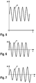
- FIG. 5 shows the distance signal a, which generates the distance measuring device 3 from the detected imbalance 26 of the shaft 2.
- a sinusoidal oscillation of the distance signal a can be seen over the time t with an amplitude A on the orthogonal.
- This distance signal a must be tracked due to temperature-induced switching level drift of the distance measuring device 3 in the adaptation device 4.
- FIG. 6 shows the adaptive signal c as a sinusoidal oscillation over the time t with the amplitude A on the orthogonal.
- This adaptive signal c is produced in the amplifier 42 by subtraction from the mean value signal b of the frequency filter 41 and the distance signal a.
- the shaft 2 wobbles about an axis center in the event of imbalance 26, ie, that an average value of the distance signal a represents a zero signal of a nominal shaft axis.
- the frequency filter 41 is to be designed such that the expected temperature change is compensated. In general, time constants of several seconds to one minute are a useful size.
- the adaptive device 4 generates by linearization an adaptive signal c, which is adjusted by the switching level drift.
- FIG. 7 shows an increasing adaptive signal f as sinusoidal wave over time t with the amplitude A.
- a variant of the adaptive signal c is shown with an increase in the unbalance 26 over the time t.
- the increase is due to an acceleration of the shaft 2.
- This rising adaptive signal f of FIG. 7 is the basis for the following description of a switch-off by means of the first comparator unit 5 and the control / control unit 6th
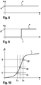
- FIG. 8 shows a constant threshold signal d with the trigger threshold D.
- This threshold signal d is fed to the second comparator 51d and serves to define a triggering threshold for a shutdown of the shaft second
- FIG. 9 shows the control signal e over the time t with a signal level S on the orthogonal.
- a control signal height E is drawn on the orthogonal.
- the first comparator 41 checks whether an amplitude A of the rising adaptive signal f (FIG. FIG. 7 ) the threshold signal d ( FIG. 8 ) exceeds.
- FIG. 9 is an exceeding of the threshold signal d at time t 'shown.
- the control signal e jumps abruptly to the control signal level E.
- the control signal e with the control signal level E is then forwarded via the comparator output 41c to the control / control unit 6.
- control signal e can be used to switch off the first electric motor 24 and the second electric motor 25.
- the control signal e can be used to switch off the first electric motor 24 and the second electric motor 25.
- a reduction of speed or torque of the first electric motor 24 and / or the second electric motor 25 is conceivable.
- FIG. 10 shows a diagram with the deflection r of the shaft 2 on a horizontal axis and a current I of the distance signal a on an orthogonal.
- a current distance course i is drawn.
- This current distance curve i has a lower switching limit 31, an upper switching limit 32 and a switching point 33.
- the lower switching limit 31 and the upper switching limit 32 thus indicate the limits of a usable range of the distance measuring device 3.
- Between the lower switching limit 31 and the upper switching limit 32 of the current-distance curve i is approximately linear or quasi-linear. As can be seen, this approximately linear region is 0.4 mm wide and extends over 1 mA. To monitor these limits, it is advantageous to provide a second comparator unit with a second comparator (not shown).
Landscapes
- Physics & Mathematics (AREA)
- General Physics & Mathematics (AREA)
- Acoustics & Sound (AREA)
- Measurement Of Mechanical Vibrations Or Ultrasonic Waves (AREA)
- Measurement Of Length, Angles, Or The Like Using Electric Or Magnetic Means (AREA)
- Testing Of Devices, Machine Parts, Or Other Structures Thereof (AREA)
Description
- Die vorliegende Erfindung betrifft eine Anordnung sowie ein Verfahren zur Schwingungsüberwachung rotierenden Bauteile, insbesondere schnelldrehender Wellen.
- Bei der Überwachung schnelldrehender Wellen wird heutzutage oft nur die Drehzahl an der Antriebsseite und der Abtriebsseite gemessen. Durch Vergleich dieser beiden Drehzahlen kann jedoch lediglich der Bruch der Welle detektiert werden.
- Zur genaueren Überwachung der Schwingung bzw. Unwucht schnelldrehender Wellen sind berührungslos arbeitende abstandserfassende Sensoren bekannt, welche jedoch meist nicht über eine hohe Signalbreite verfügen. Diejenigen Sensortypen, welche über eine ausreichend hohe Signalbreite verfügen, sind für einen Einsatzfall in schnelldrehenden Wellen wirtschaftlich uninteressant. So sind beispielsweise Triangulationssensoren mit schnellen CCD-Sensoren und Interferometern mit schnellen Auswerteschaltungen relativ kosten- und wartungsintensiv. Taktile, also berührende, Systeme scheiden für die meisten Anwendungsfälle aus.
- Die
US 4,144,578 A betrifft ein Verfahren zur Überwachung und Korrektur einer durch Bearbeitungsvorgänge beeinflussbaren physikalischen Kenngröße von in Serie bearbeiteten Werkstücken durch Bildung eines Mittelwertes aus diesen Kenngrößen mehrerer fertig bearbeiteter Werkstücke, insbesondere zur Überwachung und Korrektur des Auswuchtzustandes von Werkstücken. - Weiteren relevanten Stand der Technik zeigen
US 3331252 A undDE 4215381 A1 . - Die erfindungsgemäße Anordnung zur Schwingungsüberwachung mit den Merkmalen des Patentanspruchs 1 weist demgegenüber den Vorteil auf, dass für das benötigte Abstandsmessgerät einfache, handelsübliche Detektoren verwendet werden können. Diese Abstandsmessgeräte im Sinne der Erfindung sind wesentlich kostengünstiger als beispielsweise Triangulationssensoren und Interferometer. Etwaige Nachteile, wie beispielsweise ein thermisch bedingter Schaltpegeldrift, des einfachen Abstandsmessgerätes, werden durch die erfindungsgemäße Adaptionsvorrichtung ausgeglichen. Die Adaptationsvorrichtung setzt sich aus bekannten Bauteilen zusammen und ist somit einfach und kostengünstig herstellbar. Dies wird erfindungsgemäß dadurch erreicht, dass eine Anordnung zur Schwingungsüberwachung eines rotierenden Bauteils, umfassend ein Abstandsmessgerät, eine Adaptionsvorrichtung und eine Regel-/Steuereinheit vorgesehen wird. Dabei ist das Abstandsmessgerät ausgebildet, um einen Abstand zum rotierenden Bauteil, insbesondere zur Oberfläche einer schnellrotierenden Welle, zu messen und daraus ein Abstandssignal zu erzeugen. Die Adaptionsvorrichtung ist mit dem Abstandsmessgerät verbunden und ist dazu ausgebildet, einen Schaltpegeldrift des Abstandsmessgeräts auszugleichen. Dazu umfasst die Adaptionsvorrichtung einen Frequenzfilter, welcher ausgebildet ist, um aus dem Abstandssignal ein Mittelwertsignal zu erzeugen, und einen Verstärker, insbesondere Differenzverstärker, welcher ausgebildet ist, um aus dem Mittelwertsignal und dem Abstandssignal ein Adaptivsignal zu erzeugen. Die Regel-/Steuereinheit ist mit der Adaptionseinrichtung verbunden und dazu ausgebildet, eine Überwachungsfunktion auszuführen. Die erfindungsgemäße Adaptionsvorrichtung bildet also aus einem aktuellen Abstandssignal einen Mittelwert und kombiniert diesen mit dem Abstandssignal. Daraus wird dann das Adaptivsignal bzw. das adaptiv nachgeführte Messsignal, erzeugt. Somit ist es möglich, einen nachteiligen Schaltpegeldrift preisgünstiger Abstandsmessgeräte auszugleichen und Schwingungen auf schnelllaufenden Wellen mit einfachen Mitteln zu detektieren.
- Die Unteransprüche zeigen bevorzugte Weiterbildungen der Erfindung.
- In vorteilhafter Ausgestaltung umfasst die erfindungsgemäße Anordnung ferner einen ersten Komparator, welcher ausgebildet ist, um das Adaptivsignal mit einem Schwellwertsignal, welches eine Auslöseschwelle angibt, zu vergleichen und ein Abschaltsignal zu erzeugen, wenn das Adaptivsignal die Auslöseschwelle überschreitet. Der Komparator vergleicht also das Adaptivsignal mit einer Auslöseschwelle und kann ein Abschaltsignal an die Regelsteuereinheit senden. Somit kann die erfindungsgemäße Anordnung die Schwingung an einem rotierenden Bauteil nicht nur überwachen, sondern auch dessen Antrieb bei zu großer Unwucht abschalten. Vorzugsweise wird noch vor Erreichen einer kritischen Drehzahl eines rotierenden Bauteils, z.B. bei ca. 85 % der kritischen Drehzahl, eine Abschaltung ausgeführt um einen Wellenbruch zu verhindern. Als kritische Drehzahl wird dabei die Drehzahl des rotierenden Bauteils verstanden, bei welcher durch Unwucht auftretende Querkräfte zum Bauteilversagen führen. Somit wird in vorteilhafter Ausgestaltung der erste Komparator mit der Auslöseschwelle so ausgebildet, dass ein Abschalten bei 85 % der kritischen Drehzahl erfolgen kann. Alternativ kann die Auslöseschwelle auch vorteilhaft als Warngrenze verstanden werden. In diesem Fall wird die Drehzahl des rotierenden Bauteils reduziert anstatt die Rotation abzuschalten.
- In weiterer vorteilhafter Ausgestaltung umfasst die erfindungsgemäße Anordnung einen zweiten Komparator, welcher ausgebildet ist, um Grenzen, insbesondere begrenzte Stromstärken, des Abstandsmessgerätes und/oder der Adaptionsvorrichtung zu überwachen. Um Fehlfunktionen der Schaltung bei der Adaption bzw. Nachführung des Abstandssignals zu verhindern, muss auf die Grenzen des Abstandsmessgerätes und der Adaptionsvorrichtung geachtet werden. Dies erfolgt mit einem zweiten Komparator, welcher ausgebildet ist, um insbesondere die Stromstärken im Abstandssignal und im Adaptivsignal zu überwachen.
- Ferner vorteilhaft ist es, dass das Abstandsmessgerät ein induktiver Näherungsschalter ist, wobei das Abstandssignal ein direktes, analoges Messsignal des induktiven Näherungsschalters ist. Wie bereits diskutiert, können optisch arbeitende Messsysteme nach Stand der Technik in der Regel keine ausreichende Bandbreite messen. Dies kann jedoch hervorragend mit preiswerten induktiven Näherungsschaltern gelöst werden, bei welchen das Messsignal direkt ausgewertet wird. Wichtig ist hierbei, dass direkt das analoge Messsignal des induktiven Näherungsschalters ausgewertet wird, d.h., dass der induktive Sensor nicht als Schalter verwendet wird.
- Weiterhin vorteilhaft ist es, bei Verwendung eines induktiven Näherungsschalters, dass das Abstandssignal dem Messsignal in einem Schaltbereich des induktiven Näherungsschalters entspricht, wobei der Schaltbereich ein annähernd linearer Bereich des Messsignals um einen Schaltpunkt des induktiven Näherungsschalters ist. Das Messsignal für induktive Näherungsschalter ist meist nur in der Nähe des Schaltpunktes verwendbar. Typische Schaltpunkte liegen z.B. im Bereich von 1-2 mm. Der Schaltbereich ist dabei auf eine Breite von wenigen 1/10 mm beschränkt. In der Nähe des Arbeitspunktes bzw. Schaltpunktes kann der Signalverlauf als quasi linear oder annähernd linear betrachtet werden. In diesem eingeschränkten Schaltbereich gibt das Signal des induktiven Näherungsschalters somit direkten Aufschluss über den Abstand vom rotierenden Bauteil zum Abstandsmessgerät.
- In vorteilhafter Ausgestaltung ist der Frequenzfilter der Adaptionsvorrichtung entweder ein Tiefpassfilter oder ein Hochpassfilter. Für die Auskopplung des Adaptivsignals aus dem Abstandssignal ist sowohl ein Hochpassfilter als auch ein Tiefpassfilter denkbar und von Vorteil. Jedoch sei angemerkt, dass in den meisten Fällen der Tiefpassfilter die bessere Lösung darstellt, da hier die Adaption des Abstandssignals wesentlich stabiler verläuft.
- Weiterhin vorteilhaft ist es, das Abstandsmessgerät so auszubilden, dass es entweder die Schwingung des rotierenden Bauteils in axialer oder in radialer Richtung messen kann. In den meisten Fällen ist die Schwingung bzw. Unwucht in radialer Richtung von Interesse. Jedoch kann die erfindungsgemäße Anordnung auch zur axialen Überwachung verwendet werden. Hierbei wird das Abstandsmessgerät an einer Fläche der Welle angeordnet, wobei diese Fläche senkrecht zu einer Rotationsachse der Welle ist. Ferner vorteilhaft ist es, falls Kupplungen als Toleranzausgleich eingesetzt werden, eine Absolutüberwachung der Radialposition vorzusehen. Bei schnelllaufenden Wellen verwendete Kupplungsarten erzeugen oft eine auslegungsproportionale Querkraft und begünstigen somit das Bruchverhalten der Welle. Diese Absolutüberwachung kann ebenfalls mit abstandsmessenden Sensoren bewältigt werden.
- Die Erfindung umfasst ferner ein Verfahren zur Schwingungsüberwachung eines rotierenden Bauteils mit den Schritten: Messen eines Abstands zum Bauteil und Erzeugen eines Abstandssignals, insbesondere aus einem direkten, analogen Messsignal eines induktiven Näherungsschalters, und Ausgleichen eines Schaltpegeldrifts des Abstandssignals. Dabei umfasst das Ausgleichen des Schaltpegeldrifts die folgenden beiden Schritte: Erzeugen eines Mittelwertsignals aus dem Abstandssignal, und Erzeugen eines Adaptivsignals, insbesondere durch Differenzbildung, aus dem Mittelwertsignal und dem Abstandssignal.
- Die Vorteile der erfindungsgemäßen Anordnung gelten sinngemäß für das erfindungsgemäße Verfahren. Die vorteilhaften Ausgestaltungen der erfindungsgemäßen Anordnung kommen auch in Verbindung mit dem erfindungsgemäßen Verfahren vorteilhaft zum Einsatz.
- Ferner ist in vorteilhafter Ausgestaltung des erfindungsgemäßen Verfahrens vorgesehen, dass das Abstandssignal aus einem Abstandsmessgerät, insbesondere einem induktiven Näherungsschalter, erzeugt wird, wobei eine Minimalbandbreite des Abstandsmessgerätes mindestens dem vierfachen der Drehzahl des rotierenden Bauteils entspricht. In der Regel sollte die doppelte Bandbreite als Winkelauflösung bei Maximaldrehzahl noch sicher erfasst werden können. Als Minimalbandbreite für eine technische Nutzung sind λ/4 der Grundwelle (90° der Grundwelle) von Vorteil. Weiterhin vorteilhaft ist es, dieses Signal technisch doppelt abzutasten, d.h., die Minimalbandbreite entspricht 45° Winkelauflösung. Somit ergibt sich beispielsweise bei 20000 U/min. für 45° Winkelauflösung eine Bandbreite von ca. 2,7 kHz.
- In weiterer vorteilhafter Ausgestaltung wird das erfindungsgemäße Verfahren zur Überwachung von Wellen mit einer Drehzahl größer oder gleich 20000 U/min und/oder von Wellen eines Elektromotors für Turbolader und/oder eines Luftverdichters und/oder eins Hybridmotors und/oder eines elektrohydraulischen Systems in Windkraftanlagen und/oder eines Verteilergetriebes eingesetzt.
- Nachfolgend wird ein bevorzugtes Ausführungsbeispiel der Erfindung unter Bezugnahme auf die begleitende Zeichnung beschrieben. In der Zeichnung ist:
- Figur 1
- ein Prüfstand für eine schnelldrehende Welle, bei welchem die erfindungsgemäße Anordnung nach dem Ausführungsbeispiel zur Anwendung kommt,
- Figur 2
- eine geschnittene Darstellung der Welle aus
Figur 1 mit der erfindungsgemäßen Anordnung nach dem Ausführungsbeispiel, - Figur 3
- eine Darstellung eines Abstandsverlaufs zwischen der Welle und einem Abstandsmessgerät,
- Figur 4
- ein Schaltbild der erfindungsgemäßen Anordnung nach dem Ausführungsbeispiel,
- Figur 5-9
- Darstellungen von Signalverläufen in der erfindungsgemäßen Anordnung nach dem Ausführungsbeispiel, und
- Figur 10
- eine Darstellung eines Strom-Abstandsverlaufs in der erfindungsgemäßen Anordnung nach dem Ausführungsbeispiel.
- Nachfolgend wird unter Bezugnahme auf
Figur 1 ein Prüfstand 7 mit einer Anordnung 1 gemäß einem Ausführungsbeispiel der vorliegenden Erfindung beschrieben. Dabei ist ein erster Elektromotor 24 über eine Welle 2 (rotierendes Bauteil) mit einem zweiten Elektromotor 25 verbunden. Die Welle 2 umfasst dabei ein Torsionselement 23 zur Drehmomentmessung sowie eine Lamellenkupplung 22 zum Toleranzausgleich. Zur Schwingungsüberwachung der Welle 2 ist die Anordnung 1 an dem Prüfstand 7 angeordnet. - Die Anordnung 1 umfasst ein Abstandsmessgerät 3, ausgebildet als induktiver Näherungsschalter, eine Adaptionsvorrichtung 4, eine erste Komparatoreinheit 5 und eine Regel-/Steuereinheit 6. Die Anordnung 1 erfasst mit dem Abstandsmessgerät 3 eine Schwingung der Welle 2 und regelt bzw. steuert über die Regel-/Steuereinheit 6 den Elektromotor 25.
- Im Folgenden wird nun anhand
Figur 2 eine Platzierung des Abstandsmessgerätes 3 an der Welle 2 aufgezeigt. Eine genauere Beschreibung der Anordnung 1 folgt unter Bezugnahme aufFigur 4 . -
Figur 2 zeigt die Welle 2 in geschnittener Darstellung sowie die Anordnung 1. Die Welle 2 weist einen Drehsinn 27 im Uhrzeigersinn sowie eine Unwucht 26 (Schwingung) auf. Die Unwucht 26 alterniert mit einem Abstand zum Abstandsmessgerät 3, dargestellt als Ausschlag r. Das Abstandsmessgerät 3 der Anordnung 1 ist horizontal zu einem Umfang der Welle 2 und möglichst nahe an der Welle 2 angeordnet. -
Figur 3 stellt einen Unwuchtverlauf u dar. Dabei ist auf der horizontalen Achse ein Drehwinkel ϕ der Welle 2 aufgezeichnet. Die Orthogonale bezeichnet eine Amplitude A der Unwucht 26 mit dem maximalen Ausschlag r. Dieser Unwuchtverlauf u wird von dem Abstandsmessgerät 3 erfasst und in der Anordnung 1 weiterverarbeitet. -
Figur 4 zeigt die erfindungsgemäße Anordnung 1 nach dem Ausführungsbeispiel mit dem Abstandsmessgerät 3, der Adaptionsvorrichtung 4, der ersten Komparatoreinheit 5 sowie der Regel-/Steuereinheit 6. - Das Abstandsmessgerät 3 erzeugt ein Abstandssignal a (
Figur 5 ) und gibt dieses Abstandssignal a weiter an die Adaptionsvorrichtung 4. Die Adaptionsvorrichtung 4 wiederum erzeugt ein Adaptivsignal c (Figur 6 ) und gibt dieses Adaptivsignal c weiter an die erste Komparatoreinheit 5. Die erste Komparatoreinheit 5 erzeugt ein Steuersignal e (Figur 9 ) und gibt dieses Steuersignal e weiter an die Regel-/Steuereinheit 6. - Die Adaptionsvorrichtung 4 umfasst einen Frequenzfilter 41, ausgebildet als Tiefpassfilter, und einen Verstärker 42, ausgebildet als Differenzverstärker, mit einem ersten Eingang 42a, einem zweiten Eingang 42b sowie einem Ausgang 42c. Dem ersten Eingang 42a des Verstärkers 42 ist der Frequenzfilter 41 vorgelagert. Am Eingang der Adaptionsvorrichtung 4 befindet sich eine Verzweigung 43. Von dieser Verzweigung 43 geht das Abstandssignal a sowohl in den Frequenzfilter 41 als auch direkt in den zweiten Eingang 42b des Verstärkers 42. Der Frequenzfilter 41 erzeugt ein Mittelwertsignal b aus dem Abstandssignal a und gibt das Mittelwertsignal b an den ersten Eingang 42a des Verstärkers 42 weiter. Der Verstärker 42 erzeugt das Adaptivsignal c, welches zur Komparatoreinheit 5 weitergeleitet wird.
- Die erste Komparatoreinheit 5 besteht aus einem ersten Komparator 51 mit einem ersten Komparatoreingang 51a, einem zweiten Komparatoreingang 51b und einem Komparatorausgang 51c. Der erste Komparatoreingang 51a ist direkt mit dem Ausgang 42c des Verstärkers 42 verbunden und empfängt somit das Adaptivsignal c. Der zweite Komparatoreingang 51b empfängt ein Schwellwertsignal d (
Figur 8 ). Im ersten Komparator 51 wird das Steuersignal e erzeugt und über den Komparatorausgang 51c an die Regel-/Steuereinheit 6 weitergeleitet. - Mit dem soeben beschriebenen Aufbau der Anordnung 1 ist eine kompakte und kostengünstige Überwachungsvorrichtung für schnellaufende Wellen aufgezeigt. Der verwendete induktive Näherungsschalter ist handelsüblich und kostengünstig. Er weist zwar einen thermisch bedingten Schaltpegeldrift auf, dieser kann jedoch mit der erfindungsgemäßen Adaptionsvorrichtung 4 auf einfache und effektive Weise ausgeglichen werden. Die erste Komparatoreinheit 5 bildet zusammen mit der Regel-/Steuereinheit 6 eine universelle Schnittstelle zu einem Antrieb der Welle 2.
-
Figur 5 zeigt das Abstandssignal a, welches das Abstandsmessgerät 3 aus der detektierten Unwucht 26 der Welle 2 erzeugt. Dabei ist eine sinusförmige Schwingung des Abstandssignals a über der Zeit t mit einer Amplitude A auf der Orthogonalen zu sehen. Dieses Abstandssignal a muss aufgrund von temperaturbedingten Schaltpegeldrift des Abstandsmessgerätes 3 in der Adaptionsvorrichtung 4 nachgeführt werden. -
Figur 6 zeigt das Adaptivsignal c als sinusförmige Schwingung über der Zeit t mit der Amplitude A auf der Orthogonalen. Dieses Adaptivsignal c entsteht im Verstärker 42 durch Differenzbildung aus dem Mittelwertsignal b des Frequenzfilters 41 und dem Abstandssignal a. Hierzu ist anzumerken, dass die Welle 2 bei Unwucht 26 um einen Achsmittelpunkt taumelt, d.h., dass ein Mittelwert aus dem Abstandssignal a ein Nullsignal einer nominellen Wellenachse darstellt. Somit kann mittels einer gleitenden Mittelwertbildung im Frequenzfilter 41 das Abstandssignal a zur Bildung des Mittelwertsignals b verwendet werden. Dabei ist zu beachten, dass der Frequenzfilter 41 derart auszulegen ist, dass die zu erwartende Temperaturänderung ausgeglichen wird. In der Regel sind Zeitkonstanten von mehreren Sekunden bis eine Minute eine brauchbare Größe. Somit erzeugt die Adaptivvorrichtung 4 durch Linearisierung ein Adaptivsignal c, welches vom Schaltpegeldrift bereinigt ist. -
Figur 7 zeigt ein ansteigendes Adaptivsignal f als Sinusschwingung über der Zeit t mit der Amplitude A. InFigur 7 ist somit eine Variante des Adaptivsignals c bei einer Erhöhung der Unwucht 26 über der Zeit t dargestellt. Dadurch entsteht das ansteigende Adaptivsignal f. Das Ansteigen ist auf eine Beschleunigung der Welle 2 zurückzuführen. Dieses ansteigende Adaptivsignal f derFigur 7 ist Grundlage für die folgende Beschreibung eines Abschaltvorgangs mittels der ersten Komparatoreinheit 5 und der Regel-/Steuereinheit 6. -
Figur 8 zeigt ein konstantes Schwellwertsignal d mit der Auslöseschwelle D. Dabei bezeichnet die horizontale Achse die Zeit t und die Orthogonale die Signalhöhe S. Dieses Schwellwertsignal d wird in den zweiten Komparatoreingang 51d eingespeist und dient dort zur Definition einer Auslöseschwelle für eine Abschaltung der Welle 2. -
Figur 9 zeigt das Steuersignal e über der Zeit t mit einer Signalhöhe S auf der Orthogonalen. Auf der Orthogonalen ist dabei eine Steuersignalhöhe E eingezeichnet. Der erste Komparator 41 überprüft, ob eine Amplitude A des ansteigenden Adaptivsignals f (Figur 7 ) das Schwellwertsignal d (Figur 8 ) überschreitet. InFigur 9 ist ein Überschreiten des Schwellwertsignals d zum Zeitpunkt t' dargestellt. Zu diesem Zeitpunkt t' springt das Steuersignal e sprungartig auf die Steuersignalhöhe E. Das Steuersignal e mit der Steuersignalhöhe E wird dann über den Komparatorausgang 41c an die Regel-/Steuereinheit 6 weitergeleitet. - An der Regel-/Steuereinheit 6 kann das Steuersignal e zum Abschalten des ersten Elektromotors 24 und des zweiten Elektromotors 25 verwendet werden. Alternativ ist natürlich auch eine Reduzierung von Drehzahl oder Drehmoment des ersten Elektromotors 24 und/oder des zweiten Elektromotors 25 denkbar.
-
Figur 10 zeigt ein Diagramm mit dem Ausschlag r der Welle 2 auf einer horizontalen Achse und einer Stromstärke I des Abstandssignals a auf einer Orthogonalen. Darin ist ein Strom-Abstandsverlauf i eingezeichnet. Dieser Stromabstandsverlauf i weist eine untere Schaltgrenze 31, eine obere Schaltgrenze 32 und einen Schaltpunkt 33 auf. Die untere Schaltgrenze 31 und die obere Schaltgrenze 32 zeigen somit die Grenzen eines nutzbaren Bereiches des Abstandsmessgeräts 3 auf. Zwischen der unteren Schaltgrenze 31 und der oberen Schaltgrenze 32 verläuft der Strom-Abstandsverlauf i annähernd linear bzw. quasi linear. Wie zu sehen ist, ist dieser annähernd lineare Bereich 0,4 mm breit und erstreckt sich über 1 mA. Zur Überwachung dieser Grenzen ist es vorteilhaft, eine zweite Komparatoreinheit mit einem zweiten Komparator (nicht dargestellt) vorzusehen.
Claims (12)
- Anordnung zur Schwingungsüberwachung eines rotierenden Bauteils (2) umfassend- ein Abstandsmessgerät (3), welches ausgebildet ist, um einen Abstand (r) zum Bauteil (2) zu messen und daraus ein Abstandssignal (a) zu erzeugen,- eine Adaptionsvorrichtung (4) verbunden mit dem Abstandsmessgerät (3), um einen Schaltpegeldrift des Abstandsmessgerätes (3) auszugleichen, umfassend- einen Frequenzfilter (41), welcher ausgebildet ist, um aus dem Abstandssignal (a) ein Mittelwertsignal (b) zu erzeugen, und- einen Verstärker (42), insbesondere Differenzverstärker, welcher ausgebildet ist, um aus dem Mittelwertsignal (b) und dem Abstandssignal (a) ein Adaptivsignal (c) zu erzeugen, und- eine Regel-/Steuereinheit (6) verbunden mit der Adaptionsvorrichtung (4), welche ausgebildet ist, um eine Überwachungsfunktion auszuführen.
- Anordnung nach Anspruch 1, ferner umfassend einen ersten Komparator (51), welcher ausgebildet, um das Adaptivsignal (c) mit einem Schwellwertsignal (d), welches eine Auslöseschwelle (D) angibt, zu vergleichen und ein Steuersignal (e) zu erzeugen wenn das Adaptivsignal (c) die Auslöseschwelle (D) überschreitet.
- Anordnung nach einem der vorhergehenden Ansprüche, ferner umfassend einen zweiten Komparator, welcher ausgebildet ist, um Grenzen, insbesondere begrenzte Stromstärken, des Abstandsmessgerätes (3) und/oder der Adaptionsvorrichtung (4) zu überwachen.
- Anordnung nach einem der vorhergehenden Ansprüche, dadurch gekennzeichnet, dass das Abstandsmessgerät (3) ein induktiver Näherungsschalter ist, wobei das Abstandssignal (a) ein direktes, analoges Messsignal des induktiven Näherungsschalters ist.
- Anordnung nach Anspruch 4, dadurch gekennzeichnet, dass das Abstandssignal (a) dem Messsignal in einem Schaltbereich des induktiven Näherungsschalters entspricht, wobei der Schaltbereich ein annähernd linearer Bereich des Messsignals um einen Schaltpunkt (33) des induktiven Näherungsschalters ist.
- Anordnung nach einem der vorhergehenden Ansprüche, dadurch gekennzeichnet, dass der Frequenzfilter (41) einen Tiefpassfilter oder einen Hochpassfilter umfasst.
- Verfahren zur Schwingungsüberwachung eines rotierenden Bauteils umfassend die Schritte:- Messen eines Abstands (r) zum Bauteil (2) und Erzeugen eines Abstandssignals (a), und- Ausgleichen eines Schaltpegeldrifts des Abstandssignals (a) durch- Erzeugen eines Mittelwertsignals (b) aus dem Abstandssignal (a), und- Erzeugen eines Adaptivsignals (c), insbesondere durch Differenzbildung, aus dem Mittelwertsignal (b) und dem Abstandssignal (a).
- Verfahren nach Anspruch 7, ferner umfassend die Schritte:- Vergleichen des Adaptivsignals (c) mit einem Schwellwertsignal (d), welches eine Auslöseschwelle (D) angibt, und Erzeugen eines Steuersignals (e) wenn das Adaptivsignal (c) die Auslöseschwelle (D) überschreitet, und- Weiterleiten des Steuersignals (e) zu einer eine Regel-/Steuereinheit (6), um eine Überwachungsfunktion auszuführen.
- Verfahren nach einem der Ansprüche 7 oder 8, dadurch gekennzeichnet, dass zumindest eine Grenze, insbesondere eine begrenzte Stromstärke, des Abstandssignals (a) und/oder des Adaptivsignals (c) überwacht wird.
- Verfahren nach einem der Ansprüche 7 bis 9, dadurch gekennzeichnet, dass das Abstandssignal (a) aus einem Abstandsmessgerät (3), insbesondere einem induktiven Näherungsschalter, erzeugt wird, wobei eine Minimalbandbreite des Abstandsmessgeräts (3) mindestens dem vierfachen einer Drehzahl des Bauteils (2) entspricht.
- Verfahren nach einem der Ansprüche 7 bis 10, dadurch gekennzeichnet, dass der Abstand (r) zum Bauteil (2) in radialer Richtung zum Bauteil gemessen wird und/oder dass der Abstand (r) zum Bauteil (2) in axialer Richtung zum Bauteil (2) gemessen wird.
- Verfahren nach einem der Ansprüche 7 bis 11, dadurch gekennzeichnet, dass das Verfahren zur Überwachung von Wellen mit einer Drehzahl größer 20000 U/min und/oder von Wellen eines Elektromotors für Turbolader und/oder eines Luftverdichters und/oder eines Hybridmotors und/oder eines elektrohydraulischen Systems in Windkraftanlagen und/oder eines Verteilergetriebes eingesetzt wird.
Applications Claiming Priority (1)
| Application Number | Priority Date | Filing Date | Title |
|---|---|---|---|
| DE102008042769A DE102008042769A1 (de) | 2008-10-13 | 2008-10-13 | Anordnung zur Schwingungsüberwachung eines rotierenden Bauteils |
Publications (3)
| Publication Number | Publication Date |
|---|---|
| EP2175254A2 EP2175254A2 (de) | 2010-04-14 |
| EP2175254A3 EP2175254A3 (de) | 2016-01-20 |
| EP2175254B1 true EP2175254B1 (de) | 2019-10-09 |
Family
ID=41508838
Family Applications (1)
| Application Number | Title | Priority Date | Filing Date |
|---|---|---|---|
| EP09167797.1A Active EP2175254B1 (de) | 2008-10-13 | 2009-08-13 | Anordnung zur Schwingungsüberwachung eines rotierenden Bauteils |
Country Status (2)
| Country | Link |
|---|---|
| EP (1) | EP2175254B1 (de) |
| DE (1) | DE102008042769A1 (de) |
Families Citing this family (1)
| Publication number | Priority date | Publication date | Assignee | Title |
|---|---|---|---|---|
| JP5680526B2 (ja) * | 2011-12-28 | 2015-03-04 | 三菱重工業株式会社 | 風力発電用風車の衝撃荷重監視システム及び衝撃荷重監視方法 |
Family Cites Families (3)
| Publication number | Priority date | Publication date | Assignee | Title |
|---|---|---|---|---|
| US3331252A (en) * | 1965-03-23 | 1967-07-18 | Int Research & Dev Co Ltd | Electronic vibration analyzing apparatus |
| DE2605485B2 (de) * | 1976-02-12 | 1980-05-29 | Carl Schenck Ag, 6100 Darmstadt | Verfahren zum relativen Einstellen der Drehachsen von in Serie zu bearbeitenden Werkstücken in einer Zentriermaschine |
| DE4215381A1 (de) * | 1992-05-11 | 1993-11-18 | Siemens Ag | Anordnung zur radialen und/oder axialen Positionserfassung einer Welle |
-
2008
- 2008-10-13 DE DE102008042769A patent/DE102008042769A1/de not_active Ceased
-
2009
- 2009-08-13 EP EP09167797.1A patent/EP2175254B1/de active Active
Non-Patent Citations (1)
| Title |
|---|
| None * |
Also Published As
| Publication number | Publication date |
|---|---|
| DE102008042769A1 (de) | 2010-04-15 |
| EP2175254A3 (de) | 2016-01-20 |
| EP2175254A2 (de) | 2010-04-14 |
Similar Documents
| Publication | Publication Date | Title |
|---|---|---|
| DE112012005157B4 (de) | Verfahren und System zur synchronen Unterdrückung der unterkritischen Schwingungdes Magnetschwebe-Molekularpumpe-Rotors | |
| DE102020102065B3 (de) | Kupplungsaktor, Erfassungssystem und Verfahren zur Erfassung einer Winkelposition eines Drehbauteils | |
| EP2624089B1 (de) | Reglerstruktur zur Dämpfung niederfrequenter Schwingungen | |
| EP3063423A1 (de) | Gedämpfte lagerung einer rotorwelle | |
| EP2887023A2 (de) | Verfahren zum Bestimmen einer Drehwinkelstellung und/oder einer Drehzahl | |
| EP2669513A2 (de) | Verfahren zur Dämpfung von Torsionsschwingungen in einer Antriebsstrangkomponente | |
| DE102013225330A1 (de) | Wälzlager oder Gleitlager mit Schwingungsdämpfung | |
| EP3527950A1 (de) | Lagerlose winkelmesseinrichtung | |
| DE102013113986A1 (de) | Rotierendes System | |
| WO2012072255A1 (de) | Vorrichtung zur messung einer drehrate | |
| DE4215381A1 (de) | Anordnung zur radialen und/oder axialen Positionserfassung einer Welle | |
| EP2113758B1 (de) | Drehmomentsensor mit Telemetriesystem | |
| DE1914876A1 (de) | Vorrichtung zur kapazitiven Abstandermittlung | |
| EP4274711B1 (de) | Verfahren zur positionierung | |
| EP1956349B1 (de) | Füllstandsschalter und Verfahren zur Erfassung des Füllzustands eines in einem Behälter vorgesehenen Mediums | |
| EP2175254A2 (de) | Anordnung zur Schwingungsüberwachung eines rotierenden Bauteils | |
| EP4026753B1 (de) | Verfahren zur bestimmung des verschleisses eines lenksystems eines fahrzeugs | |
| DE102016214456A1 (de) | Positionsmesseinrichtung und Verfahren zum Betreiben einer Positionsmesseinrichtung | |
| DE102018217934A1 (de) | Positionsmesseinrichtung und Verfahren zum Betreiben einer Positionsmesseinrichtung | |
| DE102015202303A1 (de) | Kurzschlussfeste Schaltung zur Ansteuerung eines Resolvers | |
| EP2767806A1 (de) | Winkelmesseinrichtung | |
| EP2250392B1 (de) | Aktives schwingungsisolationssystem | |
| EP3483451B1 (de) | Positionserfassungsvorrichtung für einen magnetgelagerten rotor | |
| DE102004056996A1 (de) | Maschinenanordnung mit einer Maschine, die einen Grundkörper und einen Zusatzkörper aufweist | |
| WO2015082512A2 (de) | Hydrodynamische maschine mit messsystem |
Legal Events
| Date | Code | Title | Description |
|---|---|---|---|
| PUAI | Public reference made under article 153(3) epc to a published international application that has entered the european phase |
Free format text: ORIGINAL CODE: 0009012 |
|
| AK | Designated contracting states |
Kind code of ref document: A2 Designated state(s): AT BE BG CH CY CZ DE DK EE ES FI FR GB GR HR HU IE IS IT LI LT LU LV MC MK MT NL NO PL PT RO SE SI SK SM TR |
|
| PUAL | Search report despatched |
Free format text: ORIGINAL CODE: 0009013 |
|
| AK | Designated contracting states |
Kind code of ref document: A3 Designated state(s): AT BE BG CH CY CZ DE DK EE ES FI FR GB GR HR HU IE IS IT LI LT LU LV MC MK MT NL NO PL PT RO SE SI SK SM TR |
|
| RIC1 | Information provided on ipc code assigned before grant |
Ipc: G01M 13/02 20060101AFI20151214BHEP Ipc: G01H 1/00 20060101ALI20151214BHEP |
|
| 17P | Request for examination filed |
Effective date: 20160720 |
|
| RBV | Designated contracting states (corrected) |
Designated state(s): AT BE BG CH CY CZ DE DK EE ES FI FR GB GR HR HU IE IS IT LI LT LU LV MC MK MT NL NO PL PT RO SE SI SK SM TR |
|
| REG | Reference to a national code |
Ref country code: DE Ref legal event code: R079 Ref document number: 502009015980 Country of ref document: DE Free format text: PREVIOUS MAIN CLASS: G01M0013020000 Ipc: G01M0013028000 |
|
| RIC1 | Information provided on ipc code assigned before grant |
Ipc: G01H 1/00 20060101ALI20190319BHEP Ipc: G01M 13/028 20190101AFI20190319BHEP |
|
| GRAP | Despatch of communication of intention to grant a patent |
Free format text: ORIGINAL CODE: EPIDOSNIGR1 |
|
| STAA | Information on the status of an ep patent application or granted ep patent |
Free format text: STATUS: GRANT OF PATENT IS INTENDED |
|
| INTG | Intention to grant announced |
Effective date: 20190508 |
|
| GRAS | Grant fee paid |
Free format text: ORIGINAL CODE: EPIDOSNIGR3 |
|
| GRAA | (expected) grant |
Free format text: ORIGINAL CODE: 0009210 |
|
| STAA | Information on the status of an ep patent application or granted ep patent |
Free format text: STATUS: THE PATENT HAS BEEN GRANTED |
|
| AK | Designated contracting states |
Kind code of ref document: B1 Designated state(s): AT BE BG CH CY CZ DE DK EE ES FI FR GB GR HR HU IE IS IT LI LT LU LV MC MK MT NL NO PL PT RO SE SI SK SM TR |
|
| REG | Reference to a national code |
Ref country code: GB Ref legal event code: FG4D Free format text: NOT ENGLISH |
|
| REG | Reference to a national code |
Ref country code: CH Ref legal event code: EP |
|
| REG | Reference to a national code |
Ref country code: DE Ref legal event code: R096 Ref document number: 502009015980 Country of ref document: DE |
|
| REG | Reference to a national code |
Ref country code: IE Ref legal event code: FG4D Free format text: LANGUAGE OF EP DOCUMENT: GERMAN |
|
| REG | Reference to a national code |
Ref country code: AT Ref legal event code: REF Ref document number: 1189393 Country of ref document: AT Kind code of ref document: T Effective date: 20191115 |
|
| REG | Reference to a national code |
Ref country code: NL Ref legal event code: MP Effective date: 20191009 |
|
| REG | Reference to a national code |
Ref country code: LT Ref legal event code: MG4D |
|
| RAP2 | Party data changed (patent owner data changed or rights of a patent transferred) |
Owner name: ROBERT BOSCH GMBH |
|
| PG25 | Lapsed in a contracting state [announced via postgrant information from national office to epo] |
Ref country code: NL Free format text: LAPSE BECAUSE OF FAILURE TO SUBMIT A TRANSLATION OF THE DESCRIPTION OR TO PAY THE FEE WITHIN THE PRESCRIBED TIME-LIMIT Effective date: 20191009 Ref country code: LT Free format text: LAPSE BECAUSE OF FAILURE TO SUBMIT A TRANSLATION OF THE DESCRIPTION OR TO PAY THE FEE WITHIN THE PRESCRIBED TIME-LIMIT Effective date: 20191009 Ref country code: LV Free format text: LAPSE BECAUSE OF FAILURE TO SUBMIT A TRANSLATION OF THE DESCRIPTION OR TO PAY THE FEE WITHIN THE PRESCRIBED TIME-LIMIT Effective date: 20191009 Ref country code: SE Free format text: LAPSE BECAUSE OF FAILURE TO SUBMIT A TRANSLATION OF THE DESCRIPTION OR TO PAY THE FEE WITHIN THE PRESCRIBED TIME-LIMIT Effective date: 20191009 Ref country code: FI Free format text: LAPSE BECAUSE OF FAILURE TO SUBMIT A TRANSLATION OF THE DESCRIPTION OR TO PAY THE FEE WITHIN THE PRESCRIBED TIME-LIMIT Effective date: 20191009 Ref country code: BG Free format text: LAPSE BECAUSE OF FAILURE TO SUBMIT A TRANSLATION OF THE DESCRIPTION OR TO PAY THE FEE WITHIN THE PRESCRIBED TIME-LIMIT Effective date: 20200109 Ref country code: GR Free format text: LAPSE BECAUSE OF FAILURE TO SUBMIT A TRANSLATION OF THE DESCRIPTION OR TO PAY THE FEE WITHIN THE PRESCRIBED TIME-LIMIT Effective date: 20200110 Ref country code: PT Free format text: LAPSE BECAUSE OF FAILURE TO SUBMIT A TRANSLATION OF THE DESCRIPTION OR TO PAY THE FEE WITHIN THE PRESCRIBED TIME-LIMIT Effective date: 20200210 Ref country code: ES Free format text: LAPSE BECAUSE OF FAILURE TO SUBMIT A TRANSLATION OF THE DESCRIPTION OR TO PAY THE FEE WITHIN THE PRESCRIBED TIME-LIMIT Effective date: 20191009 Ref country code: NO Free format text: LAPSE BECAUSE OF FAILURE TO SUBMIT A TRANSLATION OF THE DESCRIPTION OR TO PAY THE FEE WITHIN THE PRESCRIBED TIME-LIMIT Effective date: 20200109 Ref country code: PL Free format text: LAPSE BECAUSE OF FAILURE TO SUBMIT A TRANSLATION OF THE DESCRIPTION OR TO PAY THE FEE WITHIN THE PRESCRIBED TIME-LIMIT Effective date: 20191009 |
|
| PG25 | Lapsed in a contracting state [announced via postgrant information from national office to epo] |
Ref country code: HR Free format text: LAPSE BECAUSE OF FAILURE TO SUBMIT A TRANSLATION OF THE DESCRIPTION OR TO PAY THE FEE WITHIN THE PRESCRIBED TIME-LIMIT Effective date: 20191009 Ref country code: IS Free format text: LAPSE BECAUSE OF FAILURE TO SUBMIT A TRANSLATION OF THE DESCRIPTION OR TO PAY THE FEE WITHIN THE PRESCRIBED TIME-LIMIT Effective date: 20200224 |
|
| REG | Reference to a national code |
Ref country code: DE Ref legal event code: R097 Ref document number: 502009015980 Country of ref document: DE |
|
| PG2D | Information on lapse in contracting state deleted |
Ref country code: IS |
|
| PG25 | Lapsed in a contracting state [announced via postgrant information from national office to epo] |
Ref country code: RO Free format text: LAPSE BECAUSE OF FAILURE TO SUBMIT A TRANSLATION OF THE DESCRIPTION OR TO PAY THE FEE WITHIN THE PRESCRIBED TIME-LIMIT Effective date: 20191009 Ref country code: CZ Free format text: LAPSE BECAUSE OF FAILURE TO SUBMIT A TRANSLATION OF THE DESCRIPTION OR TO PAY THE FEE WITHIN THE PRESCRIBED TIME-LIMIT Effective date: 20191009 Ref country code: EE Free format text: LAPSE BECAUSE OF FAILURE TO SUBMIT A TRANSLATION OF THE DESCRIPTION OR TO PAY THE FEE WITHIN THE PRESCRIBED TIME-LIMIT Effective date: 20191009 Ref country code: DK Free format text: LAPSE BECAUSE OF FAILURE TO SUBMIT A TRANSLATION OF THE DESCRIPTION OR TO PAY THE FEE WITHIN THE PRESCRIBED TIME-LIMIT Effective date: 20191009 Ref country code: IS Free format text: LAPSE BECAUSE OF FAILURE TO SUBMIT A TRANSLATION OF THE DESCRIPTION OR TO PAY THE FEE WITHIN THE PRESCRIBED TIME-LIMIT Effective date: 20200209 |
|
| PLBE | No opposition filed within time limit |
Free format text: ORIGINAL CODE: 0009261 |
|
| STAA | Information on the status of an ep patent application or granted ep patent |
Free format text: STATUS: NO OPPOSITION FILED WITHIN TIME LIMIT |
|
| PG25 | Lapsed in a contracting state [announced via postgrant information from national office to epo] |
Ref country code: IT Free format text: LAPSE BECAUSE OF FAILURE TO SUBMIT A TRANSLATION OF THE DESCRIPTION OR TO PAY THE FEE WITHIN THE PRESCRIBED TIME-LIMIT Effective date: 20191009 Ref country code: SK Free format text: LAPSE BECAUSE OF FAILURE TO SUBMIT A TRANSLATION OF THE DESCRIPTION OR TO PAY THE FEE WITHIN THE PRESCRIBED TIME-LIMIT Effective date: 20191009 Ref country code: SM Free format text: LAPSE BECAUSE OF FAILURE TO SUBMIT A TRANSLATION OF THE DESCRIPTION OR TO PAY THE FEE WITHIN THE PRESCRIBED TIME-LIMIT Effective date: 20191009 |
|
| 26N | No opposition filed |
Effective date: 20200710 |
|
| PGFP | Annual fee paid to national office [announced via postgrant information from national office to epo] |
Ref country code: TR Payment date: 20200810 Year of fee payment: 12 Ref country code: FR Payment date: 20200820 Year of fee payment: 12 |
|
| PG25 | Lapsed in a contracting state [announced via postgrant information from national office to epo] |
Ref country code: SI Free format text: LAPSE BECAUSE OF FAILURE TO SUBMIT A TRANSLATION OF THE DESCRIPTION OR TO PAY THE FEE WITHIN THE PRESCRIBED TIME-LIMIT Effective date: 20191009 |
|
| PG25 | Lapsed in a contracting state [announced via postgrant information from national office to epo] |
Ref country code: MC Free format text: LAPSE BECAUSE OF FAILURE TO SUBMIT A TRANSLATION OF THE DESCRIPTION OR TO PAY THE FEE WITHIN THE PRESCRIBED TIME-LIMIT Effective date: 20191009 |
|
| REG | Reference to a national code |
Ref country code: CH Ref legal event code: PL |
|
| GBPC | Gb: european patent ceased through non-payment of renewal fee |
Effective date: 20200813 |
|
| PG25 | Lapsed in a contracting state [announced via postgrant information from national office to epo] |
Ref country code: LI Free format text: LAPSE BECAUSE OF NON-PAYMENT OF DUE FEES Effective date: 20200831 Ref country code: CH Free format text: LAPSE BECAUSE OF NON-PAYMENT OF DUE FEES Effective date: 20200831 Ref country code: LU Free format text: LAPSE BECAUSE OF NON-PAYMENT OF DUE FEES Effective date: 20200813 |
|
| REG | Reference to a national code |
Ref country code: BE Ref legal event code: MM Effective date: 20200831 |
|
| PG25 | Lapsed in a contracting state [announced via postgrant information from national office to epo] |
Ref country code: BE Free format text: LAPSE BECAUSE OF NON-PAYMENT OF DUE FEES Effective date: 20200831 Ref country code: IE Free format text: LAPSE BECAUSE OF NON-PAYMENT OF DUE FEES Effective date: 20200813 Ref country code: GB Free format text: LAPSE BECAUSE OF NON-PAYMENT OF DUE FEES Effective date: 20200813 |
|
| REG | Reference to a national code |
Ref country code: AT Ref legal event code: MM01 Ref document number: 1189393 Country of ref document: AT Kind code of ref document: T Effective date: 20200813 |
|
| PG25 | Lapsed in a contracting state [announced via postgrant information from national office to epo] |
Ref country code: AT Free format text: LAPSE BECAUSE OF NON-PAYMENT OF DUE FEES Effective date: 20200813 |
|
| PGFP | Annual fee paid to national office [announced via postgrant information from national office to epo] |
Ref country code: DE Payment date: 20211025 Year of fee payment: 13 |
|
| PG25 | Lapsed in a contracting state [announced via postgrant information from national office to epo] |
Ref country code: MT Free format text: LAPSE BECAUSE OF FAILURE TO SUBMIT A TRANSLATION OF THE DESCRIPTION OR TO PAY THE FEE WITHIN THE PRESCRIBED TIME-LIMIT Effective date: 20191009 Ref country code: CY Free format text: LAPSE BECAUSE OF FAILURE TO SUBMIT A TRANSLATION OF THE DESCRIPTION OR TO PAY THE FEE WITHIN THE PRESCRIBED TIME-LIMIT Effective date: 20191009 |
|
| PG25 | Lapsed in a contracting state [announced via postgrant information from national office to epo] |
Ref country code: MK Free format text: LAPSE BECAUSE OF FAILURE TO SUBMIT A TRANSLATION OF THE DESCRIPTION OR TO PAY THE FEE WITHIN THE PRESCRIBED TIME-LIMIT Effective date: 20191009 |
|
| PG25 | Lapsed in a contracting state [announced via postgrant information from national office to epo] |
Ref country code: FR Free format text: LAPSE BECAUSE OF NON-PAYMENT OF DUE FEES Effective date: 20210831 |
|
| REG | Reference to a national code |
Ref country code: DE Ref legal event code: R119 Ref document number: 502009015980 Country of ref document: DE |
|
| PG25 | Lapsed in a contracting state [announced via postgrant information from national office to epo] |
Ref country code: DE Free format text: LAPSE BECAUSE OF NON-PAYMENT OF DUE FEES Effective date: 20230301 |
|
| PG25 | Lapsed in a contracting state [announced via postgrant information from national office to epo] |
Ref country code: TR Free format text: LAPSE BECAUSE OF NON-PAYMENT OF DUE FEES Effective date: 20210813 |