EP2175250A1 - Combination weighing apparatus - Google Patents
Combination weighing apparatus Download PDFInfo
- Publication number
- EP2175250A1 EP2175250A1 EP09172473A EP09172473A EP2175250A1 EP 2175250 A1 EP2175250 A1 EP 2175250A1 EP 09172473 A EP09172473 A EP 09172473A EP 09172473 A EP09172473 A EP 09172473A EP 2175250 A1 EP2175250 A1 EP 2175250A1
- Authority
- EP
- European Patent Office
- Prior art keywords
- spiral members
- trough
- product material
- spiral
- external peripheral
- Prior art date
- Legal status (The legal status is an assumption and is not a legal conclusion. Google has not performed a legal analysis and makes no representation as to the accuracy of the status listed.)
- Granted
Links
Images


Classifications
-
- G—PHYSICS
- G01—MEASURING; TESTING
- G01G—WEIGHING
- G01G19/00—Weighing apparatus or methods adapted for special purposes not provided for in the preceding groups
- G01G19/387—Weighing apparatus or methods adapted for special purposes not provided for in the preceding groups for combinatorial weighing, i.e. selecting a combination of articles whose total weight or number is closest to a desired value
- G01G19/393—Weighing apparatus or methods adapted for special purposes not provided for in the preceding groups for combinatorial weighing, i.e. selecting a combination of articles whose total weight or number is closest to a desired value using two or more weighing units
Definitions
- the present invention relates to a combination weighing apparatus. Background Information
- a combination weighing apparatus relating to the background art is disclosed in U.S. Patent Application Publication No. 2006/0196701 .
- This combination weighing apparatus comprises a conical distribution table, and a plurality of troughs arranged in a circle around the periphery of the distribution table.
- a core is placed in each trough, and a helical transport screw is wound around the external surface of each core.
- the cores are rotatably driven by motors, whereby the transport screws are also rotated.
- Product material supplied from the distribution table to the inside edges of the troughs is pushed from behind by the rotating transport screws and conveyed toward the outside edges of the troughs.
- the present invention was devised in view of such circumstances, and an object thereof is to obtain a combination weighing apparatus in which it is possible to effectively prevent product material from sliding off of conveying unit having trough.
- a combination weighing apparatus includes a distribution unit, a plurality of conveying units and a plurality of weighing hoppers.
- the distribution unit is configured and arranged to radially distribute product material introduced from above.
- the conveying units are arranged around a periphery of the distribution unit.
- the weighing hoppers arranged around a periphery of the conveying units.
- At least one of the conveying units has a trough and a plurality of spiral members.
- the trough has an inside edge positioned below the distribution unit and an outside edge positioned above the weighing hopper.
- the spiral members are placed above a bottom surface of the trough with each of the spiral members defining an external peripheral surface.
- the spiral members are configured and arranged to be rotatably driven so that the spiral members convey the product material supplied from the distribution unit in a vicinity of the inside edge of the trough, along the external peripheral surfaces toward a vicinity of the outside edge of the trough.
- the spiral members are configured and arranged to stop movement of the product material on the external peripheral surfaces when the spiral members are not being rotatably driven.
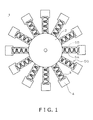
- FIG. 1 is a top plan view schematically depicting the overall configuration of a combination weighing apparatus according to an embodiment of the present invention.
- FIG. 2 is a top plan view in which the distribution table is omitted from FIG. 1 to schematically depict the conveying mechanisms and the weighing units.
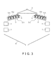
- FIG. 3 is a side cross-sectional view schematically depicting the overall configuration of the combination weighing apparatus.
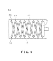
- FIG. 4 is an enlarged top plan view showing the structure of one of conveying mechanisms.
- FIG. 5 is a front view showing the structure of one of conveying mechanisms.
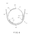
- FIG. 6 is a front view showing the structure of one of conveying mechanisms according to a modification.
- FIG. 1 is a top plan view schematically depicting the overall configuration of a combination weighing apparatus 1 according to an embodiment of the present invention.
- FIG. 2 is a top plan view in which a distribution table 2 is omitted from FIG. 1 to schematically depict conveying mechanisms 50 and the weighing units.
- FIG. 3 is a side cross-sectional view schematically depicting the overall configuration of the combination weighing apparatus 1.
- the combination weighing apparatus 1 includes a distribution table 2, conveying mechanisms 50 (conveying units), pool hoppers 4, weighing hoppers 7, and a collecting chute 8, as shown in FIGS. 1 to 3 .
- the distribution table 2 is placed in the substantial center of the main body of the combination weighing apparatus 1.
- the distribution table 2 preferably has the external shape of an eccentric cone in which the position of the apex is eccentric from the center of the bottom surface.
- the conveying mechanisms 50 are aligned in a circle around the periphery of the distribution table 2.
- the combination weighing apparatus 1 includes twelve conveying mechanisms 50, as shown in FIGS. 1 and 2 .
- the number of conveying mechanisms 50 is not limited to twelve, and may be another plural number.
- the pool hoppers 4 are aligned in a circle around the periphery of the conveying mechanisms 50. In other words, the pool hoppers 4 are arranged in a circular alignment.
- the combination weighing apparatus 1 includes twelve pool hoppers 4.
- the weighing hoppers 7 are aligned below the pool hoppers 4 in a circle around the periphery of the conveying mechanisms 50. In other words, the weighing hoppers 7 are arranged in a circular alignment.
- Each weighing hopper 7 is placed corresponding to a respective pool hopper 4. Therefore, in the present embodiment, the combination weighing apparatus 1 includes twelve weighing hoppers 7.
- the collecting chute 8 is placed below the weighing hoppers 7.
- the pool hoppers 4 and the weighing hoppers 7 together preferably correspond to the weighing units in the present embodiment.
- FIGS. 4 and 5 are, respectively, a top view and a front view showing the structure of one of conveying mechanisms 50.
- a conveying mechanism 50 is shown as seen from the outside edge of a trough 3 into the inside edge of the trough 3.
- Each of the other conveying mechanisms 50 not shown in FIGS. 4 and 5 has the same structure as the conveying mechanism 50 shown in FIGS. 4 and 5 .
- the conveying mechanism 50 includes the trough 3 and a plurality (two in the example in FIGS. 4 and 5 ) of spiral members 5A, 5B, as shown in FIGS. 4 and 5 .
- Each of the spiral members 5A and 5B is formed by a helical rod member.
- the spiral members 5A, 5B have the same shape (as used herein, the term “same shape” includes the meaning of “substantially similar shape”), and the center axes of the spiral members 5A, 5B overlap (as used herein, the term “overlap” includes the meaning of “substantially overlap”) each other with two helices formed by the spiral members 5A, 5B differing by a translation along the center axis.
- the spiral members 5A, 5B form a double helix structure.
- spiral members 5A, 5B rotate at the same speed in the same direction around the respective center axes as the respective rotational centers (as used herein, "rotate around a spiral member's center axis as a rotational center” includes the meaning of “rotate around a spiral member's center axis substantially as a rotational center”).
- the spiral members 5A, 5B are placed in a positional relationship in which a 360° helical cycle is substantially equally divided, or in this embodiment, bisected (as used herein "being bisected” includes the meaning of "being substantially bisected”).
- the spiral members 5A, 5B are placed in a positional relationship such that a circumference R hypothetically defined at the outside edge of the trough 3 is bisected by the distal ends 8A, 8B (free ends) of the spiral members 5A, 5B, as shown in FIG. 5 .
- the circumference R is defined as the rotational path of the distal ends 8A, 8B of the spiral members 5A, 5B.
- the spiral members 5A, 5B may have mutually different shapes. In such cases, it is possible that the centers of two circumferences R corresponding to the respective spiral members 5A, 5B do not overlap.
- the inside edges of the troughs 3 are positioned below the external peripheral edges of the distribution table 2, and the outside edges of the troughs 3 are positioned above the pool hoppers 4, as shown in FIG. 3 . Since the pool hoppers 4 are positioned above the weighing hoppers 7, the outside edges of the troughs 3 are also positioned above the weighing hoppers 7.
- Each trough 3 has the shape of a combination of the remaining bottom half 3a after the substantial top half of a cylinder is cut away from the cylinder, and two side walls 3b, 3c added in proximity to the outside edge of the remaining bottom half 3a (see FIG. 5 ).
- each trough 3 has a bottom surface defined as the inside surface of a semicylinder, two side surfaces continuous with the bottom surface, and an open top surface.
- the gaps between the side surfaces of the troughs 3 and the external peripheral surfaces of the spiral members 5A, 5B are wider than the gaps between the bottom surfaces of the troughs 3 and the external peripheral surfaces of the spiral members 5A, 5B as shown in Figure 5 .
- the term "external peripheral surface" of the spiral member 5A or 5B refers to a hypothetical surface defined so as to include (encompass) the entire spiral member 5A or 5B.
- the hypothetical surface encompassing the spiral member 5A or 5B is formed as a cylindrical surface since each of the spiral members 5A and 5B forms an overall shape of a cylinder.
- the spiral members 5A, 5B are turnably disposed above the bottom surfaces of the troughs 3.
- the inside ends of the spiral members 5A, 5B are fixed to rotating shafts 6.
- the rotating shafts 6 are located along the center axes of the spiral members 5A, 5B (as used herein, "being located along the center axes” includes the meaning of "being located substantially along the center axes").
- the rotating shafts 6 are rotatably driven by motors (not shown), thereby causing the spiral members 5A, 5B to be rotatably driven in a direction that conveys product material on the external peripheral surfaces of the spiral members 5A, 5B from the proximities of the inside edges of the troughs 3, which are over the external peripheral surfaces of the spiral members 5A, 5B, along the external peripheral surfaces of the spiral members 5A, 5B toward the proximities of the outside edges of the troughs 3, which are over the external peripheral surfaces of the spiral members 5A, 5B.
- the rotating shafts 6 are rotatably driven by the motors (not shown), whereby the spiral members 5A, 5B are rotatably driven in a direction that pushes product material inside the troughs 3 from the vicinities of the inside edges of the troughs 3 out toward the vicinities of the outside edges of the troughs 3.
- the spiral members 5A, 5B are placed in a positional relationship such that 360° helical cycles are bisected. Therefore, referring to FIG.
- 180° rotation of the rotating shafts 6 causes a transition from a state in which the distal ends 8A are positioned at the lowest points of the troughs 3 to a state in which the distal ends 8B are positioned at the lowest points of the troughs 3.
- the product material can be prevented from falling off in cases in which the transport screw has stopped at a position where the distal end is in contact with the product material, but in cases in which the transport screw is stopped at a position where the distal end is not in contact with the product material, the product material cannot be supported from in front by the distal end, and the product material cannot be prevented from sliding off.
- the two spiral members 5A, 5B are placed corresponding to each trough 3, and the spiral members 5A, 5B are placed in positional relationship such that the distal ends 8A, 8B of the spiral members 5A, 5B substantially equally divide the circumference R defined as the rotational paths of the distal ends 8A, 8B. Therefore, it is possible to effectively prevent unintended sliding off of the product material from the conveying mechanisms 50, because there is a high possibility that the product material will come in contact with any of the outside end vicinities of the spiral members 5A, 5B when the spiral members 5A, 5B have stopped rotating, for example.
- the troughs 3 are placed at an incline in a forward-slanted orientation so that the outside edges thereof are positioned lower than the inside edges, as shown in FIG. 3 .
- the bottom surfaces of the troughs 3 are thereby defined as downward slopes from the inside edges toward the outside edges. Since the troughs 3 are inclined downward in the direction in which product material is conveyed, the product material is readily conveyed in the conveyed direction when the spiral members 5A, 5B are being rotatably driven. When the spiral members 5A, 5B are not being rotatably driven, the product material readily stops on the external peripheral surfaces of the spiral members 5A, 5B due to being in contact with the spiral members 5A, 5B.
- the product material as the weighed object (e.g., raw meat or other foodstuffs) is dropped from above the distribution table 2 onto the center of the top surface of the distribution table 2.
- the product material dropped onto the distribution table 2 is distributed in a radial manner by the rotatably driven distribution table 2, and the product material is discharged from the external peripheral edge of the distribution table 2 and supplied from above to the proximities of the inside edges of the troughs 3, which are over the external peripheral surfaces of the spiral members 5A, 5B.
- the spiral members 5A, 5B are rotatably driven intermittently. Therefore, the product material supplied from the distribution table 2 to the proximities of the inside edges of the troughs 3, which are over the external peripheral surfaces of the spiral members 5A, 5B, mainly slides down over the external peripheral surfaces of the spiral members 5A, 5B forming downward slopes similar to the troughs 3, and the product material is conveyed over the external peripheral surfaces of the spiral members 5A, 5B from the inside edge proximities of the troughs 3 toward the outside edge proximities of the troughs 3 while being pulled along by the spiral members 5A, 5B, which are being rotatably driven.
- the product material supplied from the distribution table 2 to the inside edge proximities of the troughs 3, which are over the external peripheral surfaces of the spiral members 5A, 5B, might fall through the gaps between the spiral members 5A and the spiral members 5B into the spaces inside the spiral members 5A, 5B, and then slide down in these inside spaces.
- the product material might then be conveyed through the inside spaces from the inside edge proximities of the troughs 3 toward the outside edge proximities of the troughs 3 while being pulled along by the spiral members 5A, 5B, which are being rotatably driven in the inside spaces.
- the product material supplied from the distribution table 2 to the inside edge proximities of the troughs 3, which are over the external peripheral surfaces of the spiral members 5A, 5B, might also be conveyed over the bottom surfaces 3a of the troughs 3 from the inside edge proximities of the troughs 3 toward the outside edge proximities of the troughs 3 by sliding down the downward slopes while being pushed from behind by the rotatably driven spiral members 5A, 5B, after the product material falls onto the bottom surfaces 3a of the troughs 3 through the gaps between the spiral members 5A and the spiral members 5B.
- the product material moving over the external peripheral surfaces of the spiral members 5A, 5B might also slide over the external peripheral surfaces of the spiral members 5A, 5B down to the left and right in the conveying direction, and then get stuck in between the external peripheral surfaces of the spiral members 5A, 5B and the side surfaces 3b, 3c or bottom surfaces 3a of the troughs 3.
- the product material is conveyed over the external peripheral surfaces of the spiral members 5A, 5B from the inside edge proximities of the troughs 3 toward the outside edge proximities of troughs 3 while remaining in contact with the external peripheral surfaces of the spiral members 5A, 5B and the side surfaces 3b, 3c or bottom surfaces 3a of the troughs 3.
- the product material discharged from the conveying mechanisms 50 is supplied to the pool hoppers 4 and is temporarily retained inside the pool hoppers 4.
- the product material discharged from the pool hoppers 4 is supplied to the weighing hoppers 7 and is temporarily stored inside the weighing hoppers 7, where the product material is weighed by load cells or other weighing means (not shown).
- Calculations are then made to determine a hopper combination consisting of one or a plurality of the weighing hopper(s) 7 selected among all of the weighing hoppers 7 retaining product material, the one or the plurality of the weighing hopper(s) 7 being selected so that its or their total weight value coincides with or is nearest to a target weight.
- the product material retained in one or a plurality of selected weighing hoppers 7 is discharged.
- the product material discharged from the weighing hoppers 7 is collected by the collecting chute 8 and is discharged from the combination weighing apparatus 1 toward downstream devices (not shown).
- two spiral members 5A, 5B are placed corresponding to each trough 3, and the two spiral members 5A, 5B are placed in a positional relationship so as to bisect a helical cycle. Therefore, the overall pitch of the two spiral members 5A, 5B (the gap between the peak of a spiral member 5A and the peak of the spiral member 5B adjacent to the former peak) is narrower.
- the product material is mainly designed so as to be conveyed along the external peripheral surfaces each of which defined by the two spiral members 5A, 5B.
- the spiral members 5A, 5B are configured and arranged to hold the product material between the external peripheral surfaces and at least one of the bottom surface 3a and the side surfaces 3b, 3c of the trough 3 when the spiral members 5A, 5B are not being rotatably driven.
- the product material conveyed over the external peripheral surfaces of the spiral members 5A, 5B comes in contact with the spiral members 5A, 5B and the trough 3 when the spiral members 5A, 5B are not being rotatably driven, whereby the product material readily stops on the external peripheral surfaces of the spiral members 5A, 5B.
- the stopper function is particularly effective in cases in which the overall pitch of the spiral members 5A, 5B is half or less of the length of the product material in the conveying direction (i.e., the length of the product in the conveyed direction is twice or more of the overall pitch of the spiral members 5A, 5B).
- the reason is because product material being conveyed will, in most cases, come in contact with at least two peaks of spiral members 5A, 5B. Consequently, product material being conveyed on the external peripheral surfaces of the spiral members 5A, 5B is effectively prevented from sliding off the conveying mechanism 50 when the spiral members 5A, 5B are not being rotatably driven.
- the gaps between the side surfaces of the troughs 3 and the external peripheral surfaces of the spiral members 5A, 5B are wider than the gaps between the bottom surfaces of the troughs 3 and the external peripheral surfaces of the spiral members 5A, 5B. Consequently, the product material conveyed over the external peripheral surfaces of the spiral members 5A, 5B readily fits in or falls between the external peripheral surfaces of the spiral members 5A, 5B and the side surfaces 3b, 3c of the troughs 3, and readily stops between the external peripheral surfaces of the spiral members 5A, 5B and the side surfaces 3b, 3c of the troughs 3 when the spiral members 5A, 5B are not being rotatably driven.
- two spiral members 5A, 5B are placed corresponding to each trough 3, and the two spiral members 5A, 5B are placed in a positional relationship so as to bisect a helical cycle. Therefore, the circumference R hypothetically defined at the outside edge of the trough 3 is bisected by two distal ends 8A, 8B of the two spiral members 5A, 5B. Therefore, unintended sliding of the product material off of the conveying mechanism 50 can be effectively prevented, because there is a high possibility that the product material will come in contact in proximity to either of the distal ends 8A, 8B of the two spiral members 5A, 5B when the spiral members 5A, 5B have stopped rotating. In other words, while the rotation of the spiral members 5A, 5B remains stopped, the spiral members 5A, 5B function as stoppers for stopping unintended sliding off of the product material.
- FIG. 6 is a front view showing the structure of a conveying mechanism 50' according to the modification.
- two spiral members 5A, 5B were placed corresponding to each trough 3.
- three spiral members 5A to 5C are placed in each trough 3.
- spiral members 5A to 5C have the same shape (as used herein, the term “same shape” includes the meaning of “substantially the similar shape”), and the center axes of all the spiral members 5A to 5C overlap (as used herein, the term “overlap” includes the meanings of "substantially overlap”) each other.
- the spiral members 5A to 5C rotate at the same speed in the same direction around the respective center axes as the respective rotational centers (as used herein, "rotate around a spiral member's center axis as a rotational center” includes the meaning of "rotate around a spiral member's center axis substantially as a rotational center”).
- the spiral members 5A to 5C are placed in a positional relationship of substantially equally dividing, or in this modified embodiment, trisecting (as used herein, the term “trisect” includes the meanings “substantially trisect”) a 360° helical cycle.
- the spiral members 5A to 5C are placed in a positional relationship such that the circumference R hypothetically defined at the outside edge of the trough 3 is trisected by the distal ends 8A, 8B, 8C of the spiral members 5A, 5B, 5C, as shown in FIG. 6 .
- the circumference R is defined as the rotational path of the distal ends of the spiral members 5A to 5C.
- the spiral members 5A to 5C may have mutually different shapes.
- a 120° rotation of the rotating shaft 6 causes a transition from the distal end 8A being positioned at the lowest point of the trough 3 to the distal end 8B being positioned at the lowest point of the trough 3, and a further 120° rotation of the rotating shaft 6 causes a transition from the distal end 8B being positioned at the lowest point of the trough 3 to the distal end 8C being positioned at the lowest point of the trough 3.
- three spiral members 5A to 5C are placed corresponding to each trough 3, and the three spiral members 5A to 5C are placed in a positional relationship so as to trisect a helical cycle. Therefore, the overall pitch of the three spiral members 5A to 5C (the gap between the peak of the spiral member 5A and the peak of the spiral member 5B adjacent thereto, the gap between the peak of the spiral member 5B and the peak of the spiral member 5C adjacent thereto, or the gap between the peak of the spiral member 5C and the peak of the spiral member 5A adjacent thereto) is narrower.
- the product material is designed to be conveyed along the external peripheral surfaces each of which is defined by the three spiral members 5A to 5C.
- product material conveyed over the external peripheral surfaces of the spiral members 5A to 5C readily comes in contact with the spiral members 5A to 5C and is readily stopped on the external peripheral surfaces of the spiral members 5A to 5C when the spiral members 5A to 5C are not being rotatably driven. Consequently, when the spiral members 5A to 5C are not being rotatably driven, the product material is effectively prevented from sliding off of the conveying mechanisms 50'. In other words, while the rotation of the spiral members 5A to 5C remains stopped, the spiral members 5A to 5C function as stoppers for stopping unintended sliding off of the product material.
- the spiral members 5A to 5C while the rotation of the spiral members 5A to 5C remains stopped, there is an even higher possibility that the product material will come in contact with the vicinities of any of the distal ends 8A to 8C of the three spiral members 5A to 5C, and it is therefore to more effectively prevent unintended sliding of the product material off of the trough 3.
- the spiral members 5A to 5C function as stoppers for stopping unintended sliding off of the product material.
- the term “comprising” and its derivatives, as used herein, are intended to be open ended terms that specify the presence of the stated features, elements, components, groups, integers, and/or steps, but do not exclude the presence of other unstated features, elements, components, groups, integers and/or steps.
- the foregoing also applies to words having similar meanings such as the terms, “including”, “having” and their derivatives.
- the terms “part,” “section,” “portion,” “member” or “element” when used in the singular can have the dual meaning of a single part or a plurality of parts.
- the terms of degree such as “substantially”, “about” and “approximately” as used herein mean a reasonable amount of deviation of the modified term such that the end result is not significantly changed.
Landscapes
- Physics & Mathematics (AREA)
- General Physics & Mathematics (AREA)
- Filling Or Emptying Of Bunkers, Hoppers, And Tanks (AREA)
- Screw Conveyors (AREA)
Abstract
Description
- This application claims priority to Japanese Patent Application No.
2008-264557 filed on October 10, 2008 2008-264557 - The present invention relates to a combination weighing apparatus. Background Information
- A combination weighing apparatus relating to the background art is disclosed in
U.S. Patent Application Publication No. 2006/0196701 . This combination weighing apparatus comprises a conical distribution table, and a plurality of troughs arranged in a circle around the periphery of the distribution table. A core is placed in each trough, and a helical transport screw is wound around the external surface of each core. The cores are rotatably driven by motors, whereby the transport screws are also rotated. Product material supplied from the distribution table to the inside edges of the troughs is pushed from behind by the rotating transport screws and conveyed toward the outside edges of the troughs. - In view of the above, it will be apparent to those skilled in the art from this disclosure that there exists a need for an improved combination weighing apparatus. This invention addresses this need in the art as well as other needs, which will become apparent to those skilled in the art from this disclosure.
- In the combination weighing apparatus disclosed in
U.S. Patent Application Publication No. 2006/0196701 , only one transport screw is placed in each trough. In such cases, it is possible for a situation to arise in which the product material cannot be prevented from sliding off of the troughs, the transport screws, and other components, depending on the positioning of the product material when the transport screws have stopped rotating. - The present invention was devised in view of such circumstances, and an object thereof is to obtain a combination weighing apparatus in which it is possible to effectively prevent product material from sliding off of conveying unit having trough.
- A combination weighing apparatus according to the present invention includes a distribution unit, a plurality of conveying units and a plurality of weighing hoppers. The distribution unit is configured and arranged to radially distribute product material introduced from above. The conveying units are arranged around a periphery of the distribution unit. The weighing hoppers arranged around a periphery of the conveying units. At least one of the conveying units has a trough and a plurality of spiral members. The trough has an inside edge positioned below the distribution unit and an outside edge positioned above the weighing hopper. The spiral members are placed above a bottom surface of the trough with each of the spiral members defining an external peripheral surface. The spiral members are configured and arranged to be rotatably driven so that the spiral members convey the product material supplied from the distribution unit in a vicinity of the inside edge of the trough, along the external peripheral surfaces toward a vicinity of the outside edge of the trough. The spiral members are configured and arranged to stop movement of the product material on the external peripheral surfaces when the spiral members are not being rotatably driven.
- These and other objects, features, aspects and advantages of the present invention will become apparent to those skilled in the art from the following detailed description, which, taken in conjunction with the annexed drawings, discloses preferred embodiments of the present invention.
- Referring now to the attached drawings which form a part of this original disclosure:
-
FIG. 1 is a top plan view schematically depicting the overall configuration of a combination weighing apparatus according to an embodiment of the present invention. -
FIG. 2 is a top plan view in which the distribution table is omitted fromFIG. 1 to schematically depict the conveying mechanisms and the weighing units. -
FIG. 3 is a side cross-sectional view schematically depicting the overall configuration of the combination weighing apparatus. -
FIG. 4 is an enlarged top plan view showing the structure of one of conveying mechanisms. -
FIG. 5 is a front view showing the structure of one of conveying mechanisms. -
FIG. 6 is a front view showing the structure of one of conveying mechanisms according to a modification. - Embodiments of the present invention are described in detail hereinbelow using the drawings. Elements denoted by the same numerical symbols in different drawings represent identical or corresponding elements.
-
FIG. 1 is a top plan view schematically depicting the overall configuration of acombination weighing apparatus 1 according to an embodiment of the present invention.FIG. 2 is a top plan view in which a distribution table 2 is omitted fromFIG. 1 to schematically depictconveying mechanisms 50 and the weighing units.FIG. 3 is a side cross-sectional view schematically depicting the overall configuration of thecombination weighing apparatus 1. Thecombination weighing apparatus 1 includes a distribution table 2, conveying mechanisms 50 (conveying units),pool hoppers 4, weighinghoppers 7, and acollecting chute 8, as shown inFIGS. 1 to 3 . - The distribution table 2 is placed in the substantial center of the main body of the
combination weighing apparatus 1. The distribution table 2 preferably has the external shape of an eccentric cone in which the position of the apex is eccentric from the center of the bottom surface. Theconveying mechanisms 50 are aligned in a circle around the periphery of the distribution table 2. In the present embodiment, thecombination weighing apparatus 1 includes twelveconveying mechanisms 50, as shown inFIGS. 1 and2 . In other embodiments, the number ofconveying mechanisms 50 is not limited to twelve, and may be another plural number. Thepool hoppers 4 are aligned in a circle around the periphery of theconveying mechanisms 50. In other words, thepool hoppers 4 are arranged in a circular alignment. Eachpool hopper 4 is placed corresponding to arespective conveying mechanism 50. Therefore, in the present embodiment, thecombination weighing apparatus 1 includes twelvepool hoppers 4. The weighinghoppers 7 are aligned below thepool hoppers 4 in a circle around the periphery of theconveying mechanisms 50. In other words, theweighing hoppers 7 are arranged in a circular alignment. Each weighinghopper 7 is placed corresponding to arespective pool hopper 4. Therefore, in the present embodiment, thecombination weighing apparatus 1 includes twelve weighinghoppers 7. Thecollecting chute 8 is placed below the weighinghoppers 7. The pool hoppers 4 and theweighing hoppers 7 together preferably correspond to the weighing units in the present embodiment. -
FIGS. 4 and5 are, respectively, a top view and a front view showing the structure of one ofconveying mechanisms 50. InFIG. 5 , aconveying mechanism 50 is shown as seen from the outside edge of atrough 3 into the inside edge of thetrough 3. Each of theother conveying mechanisms 50 not shown inFIGS. 4 and5 has the same structure as theconveying mechanism 50 shown inFIGS. 4 and5 . Theconveying mechanism 50 includes thetrough 3 and a plurality (two in the example inFIGS. 4 and5 ) ofspiral members FIGS. 4 and5 . Each of thespiral members - In this embodiment, the
spiral members spiral members spiral members spiral members spiral members spiral members spiral members trough 3 is bisected by the distal ends 8A, 8B (free ends) of thespiral members FIG. 5 . The circumference R is defined as the rotational path of the distal ends 8A, 8B of thespiral members spiral members respective spiral members spiral members FIGS. 1 to 3 , for the sake of clarifying the distinction between thespiral members 5A and thespiral members 5B, thespiral members 5A are shown by solid lines, and thespiral members 5B are shown by dashed lines. - The inside edges of the
troughs 3 are positioned below the external peripheral edges of the distribution table 2, and the outside edges of thetroughs 3 are positioned above thepool hoppers 4, as shown inFIG. 3 . Since thepool hoppers 4 are positioned above the weighinghoppers 7, the outside edges of thetroughs 3 are also positioned above the weighinghoppers 7. Eachtrough 3 has the shape of a combination of the remainingbottom half 3a after the substantial top half of a cylinder is cut away from the cylinder, and twoside walls bottom half 3a (seeFIG. 5 ). Theside walls bottom halves 3a which appear when the top halves have been cut away. Therefore, eachtrough 3 has a bottom surface defined as the inside surface of a semicylinder, two side surfaces continuous with the bottom surface, and an open top surface. The gaps between the side surfaces of thetroughs 3 and the external peripheral surfaces of thespiral members troughs 3 and the external peripheral surfaces of thespiral members Figure 5 . As used herein, the term "external peripheral surface" of thespiral member entire spiral member spiral member spiral members - The
spiral members troughs 3. The inside ends of thespiral members spiral members spiral members spiral members troughs 3, which are over the external peripheral surfaces of thespiral members spiral members troughs 3, which are over the external peripheral surfaces of thespiral members troughs 3, the rotating shafts 6 are rotatably driven by the motors (not shown), whereby thespiral members troughs 3 from the vicinities of the inside edges of thetroughs 3 out toward the vicinities of the outside edges of thetroughs 3. As described above, thespiral members FIG. 5 , 180° rotation of the rotating shafts 6 causes a transition from a state in which the distal ends 8A are positioned at the lowest points of thetroughs 3 to a state in which the distal ends 8B are positioned at the lowest points of thetroughs 3. - In the conventional combination weighing apparatus disclosed in
U.S. Patent Application Publication No. 2006/0196701 as described above, only one transport screw member is placed corresponding to each trough. Therefore, the distal end of the transport screw does not return to its original position unless the transport screw member completes a full rotation (360°). In other words, a helical cycle is 360° in the conventional combination weighing apparatus. Therefore, a situation may arise in which the product material cannot be prevented from sliding off the trough, depending on the position of the distal end of the transport screw when rotation has stopped. This is because the product material can be prevented from falling off in cases in which the transport screw has stopped at a position where the distal end is in contact with the product material, but in cases in which the transport screw is stopped at a position where the distal end is not in contact with the product material, the product material cannot be supported from in front by the distal end, and the product material cannot be prevented from sliding off. - On the other hand, with the
combination weighing apparatus 1 according to the present embodiment, the twospiral members trough 3, and thespiral members spiral members mechanisms 50, because there is a high possibility that the product material will come in contact with any of the outside end vicinities of thespiral members spiral members - The
troughs 3 are placed at an incline in a forward-slanted orientation so that the outside edges thereof are positioned lower than the inside edges, as shown inFIG. 3 . The bottom surfaces of thetroughs 3 are thereby defined as downward slopes from the inside edges toward the outside edges. Since thetroughs 3 are inclined downward in the direction in which product material is conveyed, the product material is readily conveyed in the conveyed direction when thespiral members spiral members spiral members spiral members - The following is a description, made with reference to
FIGS. 1 through 5 , of the action of thecombination weighing apparatus 1. The product material as the weighed object (e.g., raw meat or other foodstuffs) is dropped from above the distribution table 2 onto the center of the top surface of the distribution table 2. The product material dropped onto the distribution table 2 is distributed in a radial manner by the rotatably driven distribution table 2, and the product material is discharged from the external peripheral edge of the distribution table 2 and supplied from above to the proximities of the inside edges of thetroughs 3, which are over the external peripheral surfaces of thespiral members - In the conveying
mechanisms 50, thespiral members troughs 3, which are over the external peripheral surfaces of thespiral members spiral members troughs 3, and the product material is conveyed over the external peripheral surfaces of thespiral members troughs 3 toward the outside edge proximities of thetroughs 3 while being pulled along by thespiral members troughs 3, which are over the external peripheral surfaces of thespiral members spiral members 5A and thespiral members 5B into the spaces inside thespiral members troughs 3 toward the outside edge proximities of thetroughs 3 while being pulled along by thespiral members troughs 3, which are over the external peripheral surfaces of thespiral members troughs 3 from the inside edge proximities of thetroughs 3 toward the outside edge proximities of thetroughs 3 by sliding down the downward slopes while being pushed from behind by the rotatably drivenspiral members troughs 3 through the gaps between thespiral members 5A and thespiral members 5B. The product material moving over the external peripheral surfaces of thespiral members spiral members spiral members bottom surfaces 3a of thetroughs 3. In such cases, the product material is conveyed over the external peripheral surfaces of thespiral members troughs 3 toward the outside edge proximities oftroughs 3 while remaining in contact with the external peripheral surfaces of thespiral members bottom surfaces 3a of thetroughs 3. - The product material discharged from the conveying
mechanisms 50 is supplied to thepool hoppers 4 and is temporarily retained inside thepool hoppers 4. The product material discharged from thepool hoppers 4 is supplied to the weighinghoppers 7 and is temporarily stored inside the weighinghoppers 7, where the product material is weighed by load cells or other weighing means (not shown). Calculations are then made to determine a hopper combination consisting of one or a plurality of the weighing hopper(s) 7 selected among all of the weighinghoppers 7 retaining product material, the one or the plurality of the weighing hopper(s) 7 being selected so that its or their total weight value coincides with or is nearest to a target weight. And the product material retained in one or a plurality of selected weighinghoppers 7 is discharged. The product material discharged from the weighinghoppers 7 is collected by the collectingchute 8 and is discharged from thecombination weighing apparatus 1 toward downstream devices (not shown). - As described above, with the
combination weighing apparatus 1 according to the present embodiment, twospiral members trough 3, and the twospiral members spiral members spiral member 5A and the peak of thespiral member 5B adjacent to the former peak) is narrower. The product material is mainly designed so as to be conveyed along the external peripheral surfaces each of which defined by the twospiral members spiral members spiral members spiral members spiral members spiral members mechanisms 50. In other words, while the rotation of thespiral members spiral members spiral members bottom surface 3a and the side surfaces 3b, 3c of thetrough 3 when thespiral members spiral members spiral members trough 3 when thespiral members spiral members - The stopper function is particularly effective in cases in which the overall pitch of the
spiral members spiral members spiral members spiral members mechanism 50 when thespiral members - With the
combination weighing apparatus 1 according to the present embodiment, product material conveyed over the external peripheral surfaces of thespiral members spiral members troughs 3 when thespiral members spiral members mechanisms 50 when thespiral members spiral members spiral members troughs 3 collectively function as stoppers for stopping unintended sliding off of the product material. - With the
combination weighing apparatus 1 according to the present embodiment, the gaps between the side surfaces of thetroughs 3 and the external peripheral surfaces of thespiral members troughs 3 and the external peripheral surfaces of thespiral members spiral members spiral members troughs 3, and readily stops between the external peripheral surfaces of thespiral members troughs 3 when thespiral members - With the
combination weighing apparatus 1 according to the present embodiment, twospiral members trough 3, and the twospiral members trough 3 is bisected by twodistal ends 8A, 8B of the twospiral members mechanism 50 can be effectively prevented, because there is a high possibility that the product material will come in contact in proximity to either of the distal ends 8A, 8B of the twospiral members spiral members spiral members spiral members -
FIG. 6 is a front view showing the structure of a conveying mechanism 50' according to the modification. In the embodiment described above, twospiral members trough 3. On the other hand, in this modified example, threespiral members 5A to 5C are placed in eachtrough 3. - All of the
spiral members 5A to 5C have the same shape (as used herein, the term "same shape" includes the meaning of "substantially the similar shape"), and the center axes of all thespiral members 5A to 5C overlap (as used herein, the term "overlap" includes the meanings of "substantially overlap") each other. Thespiral members 5A to 5C rotate at the same speed in the same direction around the respective center axes as the respective rotational centers (as used herein, "rotate around a spiral member's center axis as a rotational center" includes the meaning of "rotate around a spiral member's center axis substantially as a rotational center"). Thespiral members 5A to 5C are placed in a positional relationship of substantially equally dividing, or in this modified embodiment, trisecting (as used herein, the term "trisect" includes the meanings "substantially trisect") a 360° helical cycle. In other words, thespiral members 5A to 5C are placed in a positional relationship such that the circumference R hypothetically defined at the outside edge of thetrough 3 is trisected by the distal ends 8A, 8B, 8C of thespiral members FIG. 6 . The circumference R is defined as the rotational path of the distal ends of thespiral members 5A to 5C. In another modification, thespiral members 5A to 5C may have mutually different shapes. In such cases, it is possible that the centers of three circumferences R corresponding to therespective spiral members 5A to 5C do not overlap. However, in those cases, when all of thespiral members 5A to 5C are moved in parallel (moved without rotating) so that their centers all overlap, the three half lines extending from the coincident center toward the distal ends 8A to 8C trisect the three circumferences R, as in the modified example shown inFIG. 6 . Therefore, a 120° rotation of the rotating shaft 6 causes a transition from the distal end 8A being positioned at the lowest point of thetrough 3 to thedistal end 8B being positioned at the lowest point of thetrough 3, and a further 120° rotation of the rotating shaft 6 causes a transition from thedistal end 8B being positioned at the lowest point of thetrough 3 to the distal end 8C being positioned at the lowest point of thetrough 3. - According to the modification example shown in
FIG. 6 , threespiral members 5A to 5C are placed corresponding to eachtrough 3, and the threespiral members 5A to 5C are placed in a positional relationship so as to trisect a helical cycle. Therefore, the overall pitch of the threespiral members 5A to 5C (the gap between the peak of thespiral member 5A and the peak of thespiral member 5B adjacent thereto, the gap between the peak of thespiral member 5B and the peak of thespiral member 5C adjacent thereto, or the gap between the peak of thespiral member 5C and the peak of thespiral member 5A adjacent thereto) is narrower. The product material is designed to be conveyed along the external peripheral surfaces each of which is defined by the threespiral members 5A to 5C. Therefore, product material conveyed over the external peripheral surfaces of thespiral members 5A to 5C readily comes in contact with thespiral members 5A to 5C and is readily stopped on the external peripheral surfaces of thespiral members 5A to 5C when thespiral members 5A to 5C are not being rotatably driven. Consequently, when thespiral members 5A to 5C are not being rotatably driven, the product material is effectively prevented from sliding off of the conveying mechanisms 50'. In other words, while the rotation of thespiral members 5A to 5C remains stopped, thespiral members 5A to 5C function as stoppers for stopping unintended sliding off of the product material. - According to the modified example, while the rotation of the
spiral members 5A to 5C remains stopped, there is an even higher possibility that the product material will come in contact with the vicinities of any of the distal ends 8A to 8C of the threespiral members 5A to 5C, and it is therefore to more effectively prevent unintended sliding of the product material off of thetrough 3. In other words, while the rotation of thespiral members 5A to 5C remains stopped, thespiral members 5A to 5C function as stoppers for stopping unintended sliding off of the product material. - It is also possible to place four or more spiral members in one
trough 3. - In understanding the scope of the present invention, the term "comprising" and its derivatives, as used herein, are intended to be open ended terms that specify the presence of the stated features, elements, components, groups, integers, and/or steps, but do not exclude the presence of other unstated features, elements, components, groups, integers and/or steps. The foregoing also applies to words having similar meanings such as the terms, "including", "having" and their derivatives. Also, the terms "part," "section," "portion," "member" or "element" when used in the singular can have the dual meaning of a single part or a plurality of parts. The terms of degree such as "substantially", "about" and "approximately" as used herein mean a reasonable amount of deviation of the modified term such that the end result is not significantly changed.
- While only selected embodiments have been chosen to illustrate the present invention, it will be apparent to those skilled in the art from this disclosure that various changes and modifications can be made herein without departing from the scope of the invention as defined in the appended claims. For example, the size, shape, location or orientation of the various components can be changed as needed and/or desired. Components that are shown directly connected or contacting each other can have intermediate structures disposed between them. The functions of one element can be performed by two, and vice versa. The structures and functions of one embodiment can be adopted in another embodiment. It is not necessary for all advantages to be present in a particular embodiment at the same time. Every feature which is unique from the prior art, alone or in combination with other features, also should be considered a separate description of further inventions by the applicant, including the structural and/or functional concepts embodied by such feature(s). Thus, the foregoing descriptions of the embodiments according to the present invention are provided for illustration only, and not for the purpose of limiting the invention as defined by the appended claims and their equivalents.
Claims (6)
- A combination weighing apparatus comprising:a distribution unit configured and arranged to radially distribute product material introduced from above;a plurality of conveying units arranged around a periphery of the distribution unit; anda plurality of weighing hoppers arranged around a periphery of the conveying units,at least one of the conveying units havinga trough having an inside edge positioned below the distribution unit and an outside edge positioned above the weighing hopper, anda plurality of spiral members placed above a bottom surface of the trough with each of the spiral members defining an external peripheral surface, the spiral members being configured and arranged to be rotatably driven so that the spiral members convey the product material supplied from the distribution unit in a vicinity of the inside edge of the trough, along the external peripheral surfaces toward a vicinity of the outside edge of the trough,the spiral members being configured and arranged to stop movement of the product material on the external peripheral surfaces when the spiral members are not being rotatably driven.
- The combination weighing apparatus according to claim 1, whereinthe spiral members are configured and arranged to hold the product material between the external peripheral surfaces and at least one of the bottom surface and a side surface of the trough when the spiral members are not being rotatably driven.
- The combination weighing apparatus according to claim 1 or 2, whereinthe trough and the spiral members are arranged so that a gap between the side surface of the trough and the external peripheral surfaces of the spiral members is wider than a gap between the bottom surface of the trough and the external peripheral surfaces of the spiral members.
- The combination weighing apparatus according to any one of claims 1 to 3, whereinthe spiral members are placed with respect to each other such that distal ends of the spiral members are disposed in positions that substantially equally divide circumferences defined as rotational paths of the distal ends, andthe distal ends of the spiral members are configured and arranged as stoppers that stop the product material from sliding off the conveying unit when the spiral members are not being rotatably driven.
- The combination weighing apparatus according to any one of claims 1 to 4, whereinan overall pitch of the spiral members is equal to or less than half of a length of the product material in a direction in which the product material is conveyed.
- The combination weighing apparatus according to any one of claims 1 to 5, whereinthe trough is placed with an inclined orientation so that the outside edge is positioned lower than the inside edge.
Applications Claiming Priority (1)
| Application Number | Priority Date | Filing Date | Title |
|---|---|---|---|
| JP2008264557 | 2008-10-10 |
Publications (2)
| Publication Number | Publication Date |
|---|---|
| EP2175250A1 true EP2175250A1 (en) | 2010-04-14 |
| EP2175250B1 EP2175250B1 (en) | 2015-12-16 |
Family
ID=41343294
Family Applications (1)
| Application Number | Title | Priority Date | Filing Date |
|---|---|---|---|
| EP09172473.2A Active EP2175250B1 (en) | 2008-10-10 | 2009-10-07 | Combination weighing apparatus |
Country Status (4)
| Country | Link |
|---|---|
| US (1) | US8188383B2 (en) |
| EP (1) | EP2175250B1 (en) |
| CN (1) | CN101726350B (en) |
| DK (1) | DK2175250T3 (en) |
Cited By (2)
| Publication number | Priority date | Publication date | Assignee | Title |
|---|---|---|---|---|
| US20130186696A1 (en) * | 2012-01-25 | 2013-07-25 | Marel A/S | Combination weigher |
| WO2019058114A1 (en) * | 2017-09-19 | 2019-03-28 | Ishida Europe Limited | Weighing apparatus and method for weighing food product |
Families Citing this family (4)
| Publication number | Priority date | Publication date | Assignee | Title |
|---|---|---|---|---|
| US8729410B2 (en) * | 2005-03-03 | 2014-05-20 | Cabinplant International A/S | Arrangement for conveying controlled portions of a product material to a combinational weighing system consisting of a transport screw with a quick release mechanism |
| EP2484593A1 (en) * | 2011-02-04 | 2012-08-08 | Cabinplant International A/S | An apparatus for conveying and selectively discharging products |
| WO2013085440A1 (en) | 2011-12-08 | 2013-06-13 | Mixmo AB | Dispensing device |
| WO2018130646A1 (en) * | 2017-01-13 | 2018-07-19 | Marel A/S | A screw feeder for a combination weigher |
Citations (3)
| Publication number | Priority date | Publication date | Assignee | Title |
|---|---|---|---|---|
| US20060196701A1 (en) * | 2005-03-03 | 2006-09-07 | Cabinplant International A/S | Weighing arrangement |
| JP2008264557A (en) | 2007-04-23 | 2008-11-06 | Cathrx Ltd | Catheter control |
| EP2116823A2 (en) * | 2008-05-09 | 2009-11-11 | Ishida Co., Ltd. | Combination weighing apparatus |
Family Cites Families (15)
| Publication number | Priority date | Publication date | Assignee | Title |
|---|---|---|---|---|
| US3439836A (en) * | 1967-01-27 | 1969-04-22 | Ronald J Ricciardi | Apparatus for conditioning and dispensing particulated material |
| US3702128A (en) * | 1971-03-26 | 1972-11-07 | Celanese Corp | Solids feeder apparatus |
| US4057225A (en) * | 1976-07-14 | 1977-11-08 | Esm Inc. | Screw feeder for granular material |
| US5050777A (en) * | 1990-01-02 | 1991-09-24 | Whirlpool Corporation | Ice dispenser conveying apparatus having a rotating blade auger that operates in connection with a baffle opening to prevent wedging of ice bodies therebetween |
| US5143166A (en) * | 1991-02-01 | 1992-09-01 | Hough Richard M | Micro weighing system |
| US5524796A (en) * | 1994-08-24 | 1996-06-11 | Hyer Industries, Inc. | Screw feeder with multiple concentric flights |
| FR2759357B1 (en) * | 1997-02-13 | 1999-03-19 | Solignac Ind Sa | DEVICE FOR THE AUTOMATED SAMPLING OF PRECISE QUANTITIES OF SOLID PRODUCTS (POWDERS ...) WITH VERY VARIOUS PHYSICAL CHARACTERISTICS |
| DE19847241B4 (en) * | 1998-10-14 | 2004-09-09 | Bühler AG | Device for dosing or dispensing press cakes, in particular pigment press cakes or other substances |
| JP4278119B2 (en) | 1998-11-17 | 2009-06-10 | 日本フローダ株式会社 | Cyclone type garbage separator |
| CN2597963Y (en) * | 2002-11-14 | 2004-01-07 | 上海交通大学 | Inclined insertion installation type automatic medicine tank and weighing device |
| US8729410B2 (en) * | 2005-03-03 | 2014-05-20 | Cabinplant International A/S | Arrangement for conveying controlled portions of a product material to a combinational weighing system consisting of a transport screw with a quick release mechanism |
| EP1698868A1 (en) * | 2005-03-03 | 2006-09-06 | Cabinplant International A/S | Weighing arrangement |
| JP4343937B2 (en) | 2005-09-21 | 2009-10-14 | 株式会社イシダ | Combination weighing device |
| US7732717B2 (en) | 2005-09-21 | 2010-06-08 | Ishida Co., Ltd. | Combination weighing apparatus with dispersion unit for dispersing articles |
| JP5124348B2 (en) * | 2008-05-30 | 2013-01-23 | 株式会社イシダ | Combination weighing device |
-
2009
- 2009-09-24 US US12/566,360 patent/US8188383B2/en active Active
- 2009-10-07 EP EP09172473.2A patent/EP2175250B1/en active Active
- 2009-10-07 DK DK09172473.2T patent/DK2175250T3/en active
- 2009-10-09 CN CN2009101512928A patent/CN101726350B/en active Active
Patent Citations (3)
| Publication number | Priority date | Publication date | Assignee | Title |
|---|---|---|---|---|
| US20060196701A1 (en) * | 2005-03-03 | 2006-09-07 | Cabinplant International A/S | Weighing arrangement |
| JP2008264557A (en) | 2007-04-23 | 2008-11-06 | Cathrx Ltd | Catheter control |
| EP2116823A2 (en) * | 2008-05-09 | 2009-11-11 | Ishida Co., Ltd. | Combination weighing apparatus |
Cited By (2)
| Publication number | Priority date | Publication date | Assignee | Title |
|---|---|---|---|---|
| US20130186696A1 (en) * | 2012-01-25 | 2013-07-25 | Marel A/S | Combination weigher |
| WO2019058114A1 (en) * | 2017-09-19 | 2019-03-28 | Ishida Europe Limited | Weighing apparatus and method for weighing food product |
Also Published As
| Publication number | Publication date |
|---|---|
| US20100089666A1 (en) | 2010-04-15 |
| EP2175250B1 (en) | 2015-12-16 |
| US8188383B2 (en) | 2012-05-29 |
| DK2175250T3 (en) | 2016-02-29 |
| CN101726350A (en) | 2010-06-09 |
| CN101726350B (en) | 2012-04-18 |
Similar Documents
| Publication | Publication Date | Title |
|---|---|---|
| EP2175250B1 (en) | Combination weighing apparatus | |
| US7732718B2 (en) | Combination weighing apparatus with conveying unit including trough and spiral member | |
| US8118652B2 (en) | Beater and feed mechanism for a combine harvester | |
| JP2009270986A (en) | Combined weighing instrument | |
| JP3195388U (en) | Combination weighing device | |
| WO2009034442A2 (en) | Auger conveyors | |
| JP2015232548A (en) | Method and apparatus for grading food piece | |
| CN113677607B (en) | Discharge conveyor with reversing rollers | |
| WO2013110278A1 (en) | A combination weigher | |
| JP5124348B2 (en) | Combination weighing device | |
| JP5280881B2 (en) | Combination weighing device | |
| JP5230365B2 (en) | Combination weighing device | |
| JP4651130B2 (en) | Combination weighing device | |
| CN201089094Y (en) | An automatic feeding and checking device for conical shell processing | |
| US6722491B2 (en) | Feeder tube for bulk product | |
| SE516935C2 (en) | Aggregates for the transport of bulk goods, paddle means for such an aggregate and loading and unloading plant comprising one or more such aggregates | |
| JP2015215271A (en) | Weighing device | |
| JP2009276157A (en) | Combination weighing apparatus | |
| CN208103165U (en) | A kind of withered conveying flood dragon of oil expression | |
| JP5855308B1 (en) | Combination weighing device | |
| CN111566460A (en) | Weighing device and method for weighing a food product | |
| JP3596411B2 (en) | Transfer device for powdery and granular objects | |
| EP1385763A2 (en) | Feeder tube for bulk product | |
| EP3257368A1 (en) | Device for distributing material in granules or in filaments | |
| JP2016102798A (en) | Combination weighing apparatus |
Legal Events
| Date | Code | Title | Description |
|---|---|---|---|
| PUAI | Public reference made under article 153(3) epc to a published international application that has entered the european phase |
Free format text: ORIGINAL CODE: 0009012 |
|
| AK | Designated contracting states |
Kind code of ref document: A1 Designated state(s): AT BE BG CH CY CZ DE DK EE ES FI FR GB GR HR HU IE IS IT LI LT LU LV MC MK MT NL NO PL PT RO SE SI SK SM TR |
|
| AX | Request for extension of the european patent |
Extension state: AL BA RS |
|
| 17P | Request for examination filed |
Effective date: 20101013 |
|
| 17Q | First examination report despatched |
Effective date: 20101112 |
|
| GRAP | Despatch of communication of intention to grant a patent |
Free format text: ORIGINAL CODE: EPIDOSNIGR1 |
|
| RIC1 | Information provided on ipc code assigned before grant |
Ipc: G01G 19/393 20060101AFI20150610BHEP |
|
| INTG | Intention to grant announced |
Effective date: 20150626 |
|
| RIN1 | Information on inventor provided before grant (corrected) |
Inventor name: MIKAMI, YOSHIHARU |
|
| GRAS | Grant fee paid |
Free format text: ORIGINAL CODE: EPIDOSNIGR3 |
|
| GRAA | (expected) grant |
Free format text: ORIGINAL CODE: 0009210 |
|
| AK | Designated contracting states |
Kind code of ref document: B1 Designated state(s): AT BE BG CH CY CZ DE DK EE ES FI FR GB GR HR HU IE IS IT LI LT LU LV MC MK MT NL NO PL PT RO SE SI SK SM TR |
|
| REG | Reference to a national code |
Ref country code: GB Ref legal event code: FG4D |
|
| REG | Reference to a national code |
Ref country code: CH Ref legal event code: EP |
|
| REG | Reference to a national code |
Ref country code: IE Ref legal event code: FG4D |
|
| REG | Reference to a national code |
Ref country code: AT Ref legal event code: REF Ref document number: 765783 Country of ref document: AT Kind code of ref document: T Effective date: 20160115 |
|
| REG | Reference to a national code |
Ref country code: DE Ref legal event code: R096 Ref document number: 602009035208 Country of ref document: DE |
|
| REG | Reference to a national code |
Ref country code: DK Ref legal event code: T3 Effective date: 20160225 |
|
| REG | Reference to a national code |
Ref country code: NL Ref legal event code: MP Effective date: 20151216 |
|
| REG | Reference to a national code |
Ref country code: LT Ref legal event code: MG4D |
|
| PG25 | Lapsed in a contracting state [announced via postgrant information from national office to epo] |
Ref country code: LT Free format text: LAPSE BECAUSE OF FAILURE TO SUBMIT A TRANSLATION OF THE DESCRIPTION OR TO PAY THE FEE WITHIN THE PRESCRIBED TIME-LIMIT Effective date: 20151216 Ref country code: HR Free format text: LAPSE BECAUSE OF FAILURE TO SUBMIT A TRANSLATION OF THE DESCRIPTION OR TO PAY THE FEE WITHIN THE PRESCRIBED TIME-LIMIT Effective date: 20151216 Ref country code: NO Free format text: LAPSE BECAUSE OF FAILURE TO SUBMIT A TRANSLATION OF THE DESCRIPTION OR TO PAY THE FEE WITHIN THE PRESCRIBED TIME-LIMIT Effective date: 20160316 |
|
| REG | Reference to a national code |
Ref country code: AT Ref legal event code: MK05 Ref document number: 765783 Country of ref document: AT Kind code of ref document: T Effective date: 20151216 |
|
| PG25 | Lapsed in a contracting state [announced via postgrant information from national office to epo] |
Ref country code: SE Free format text: LAPSE BECAUSE OF FAILURE TO SUBMIT A TRANSLATION OF THE DESCRIPTION OR TO PAY THE FEE WITHIN THE PRESCRIBED TIME-LIMIT Effective date: 20151216 Ref country code: GR Free format text: LAPSE BECAUSE OF FAILURE TO SUBMIT A TRANSLATION OF THE DESCRIPTION OR TO PAY THE FEE WITHIN THE PRESCRIBED TIME-LIMIT Effective date: 20160317 Ref country code: LV Free format text: LAPSE BECAUSE OF FAILURE TO SUBMIT A TRANSLATION OF THE DESCRIPTION OR TO PAY THE FEE WITHIN THE PRESCRIBED TIME-LIMIT Effective date: 20151216 Ref country code: NL Free format text: LAPSE BECAUSE OF FAILURE TO SUBMIT A TRANSLATION OF THE DESCRIPTION OR TO PAY THE FEE WITHIN THE PRESCRIBED TIME-LIMIT Effective date: 20151216 Ref country code: FI Free format text: LAPSE BECAUSE OF FAILURE TO SUBMIT A TRANSLATION OF THE DESCRIPTION OR TO PAY THE FEE WITHIN THE PRESCRIBED TIME-LIMIT Effective date: 20151216 |
|
| PG25 | Lapsed in a contracting state [announced via postgrant information from national office to epo] |
Ref country code: IT Free format text: LAPSE BECAUSE OF FAILURE TO SUBMIT A TRANSLATION OF THE DESCRIPTION OR TO PAY THE FEE WITHIN THE PRESCRIBED TIME-LIMIT Effective date: 20151216 Ref country code: CZ Free format text: LAPSE BECAUSE OF FAILURE TO SUBMIT A TRANSLATION OF THE DESCRIPTION OR TO PAY THE FEE WITHIN THE PRESCRIBED TIME-LIMIT Effective date: 20151216 Ref country code: ES Free format text: LAPSE BECAUSE OF FAILURE TO SUBMIT A TRANSLATION OF THE DESCRIPTION OR TO PAY THE FEE WITHIN THE PRESCRIBED TIME-LIMIT Effective date: 20151216 |
|
| PG25 | Lapsed in a contracting state [announced via postgrant information from national office to epo] |
Ref country code: EE Free format text: LAPSE BECAUSE OF FAILURE TO SUBMIT A TRANSLATION OF THE DESCRIPTION OR TO PAY THE FEE WITHIN THE PRESCRIBED TIME-LIMIT Effective date: 20151216 Ref country code: AT Free format text: LAPSE BECAUSE OF FAILURE TO SUBMIT A TRANSLATION OF THE DESCRIPTION OR TO PAY THE FEE WITHIN THE PRESCRIBED TIME-LIMIT Effective date: 20151216 Ref country code: SK Free format text: LAPSE BECAUSE OF FAILURE TO SUBMIT A TRANSLATION OF THE DESCRIPTION OR TO PAY THE FEE WITHIN THE PRESCRIBED TIME-LIMIT Effective date: 20151216 Ref country code: SM Free format text: LAPSE BECAUSE OF FAILURE TO SUBMIT A TRANSLATION OF THE DESCRIPTION OR TO PAY THE FEE WITHIN THE PRESCRIBED TIME-LIMIT Effective date: 20151216 Ref country code: RO Free format text: LAPSE BECAUSE OF FAILURE TO SUBMIT A TRANSLATION OF THE DESCRIPTION OR TO PAY THE FEE WITHIN THE PRESCRIBED TIME-LIMIT Effective date: 20151216 Ref country code: PT Free format text: LAPSE BECAUSE OF FAILURE TO SUBMIT A TRANSLATION OF THE DESCRIPTION OR TO PAY THE FEE WITHIN THE PRESCRIBED TIME-LIMIT Effective date: 20160418 Ref country code: IS Free format text: LAPSE BECAUSE OF FAILURE TO SUBMIT A TRANSLATION OF THE DESCRIPTION OR TO PAY THE FEE WITHIN THE PRESCRIBED TIME-LIMIT Effective date: 20160416 |
|
| REG | Reference to a national code |
Ref country code: DE Ref legal event code: R097 Ref document number: 602009035208 Country of ref document: DE |
|
| REG | Reference to a national code |
Ref country code: FR Ref legal event code: PLFP Year of fee payment: 8 |
|
| PLBE | No opposition filed within time limit |
Free format text: ORIGINAL CODE: 0009261 |
|
| STAA | Information on the status of an ep patent application or granted ep patent |
Free format text: STATUS: NO OPPOSITION FILED WITHIN TIME LIMIT |
|
| PG25 | Lapsed in a contracting state [announced via postgrant information from national office to epo] |
Ref country code: PL Free format text: LAPSE BECAUSE OF FAILURE TO SUBMIT A TRANSLATION OF THE DESCRIPTION OR TO PAY THE FEE WITHIN THE PRESCRIBED TIME-LIMIT Effective date: 20151216 |
|
| 26N | No opposition filed |
Effective date: 20160919 |
|
| PG25 | Lapsed in a contracting state [announced via postgrant information from national office to epo] |
Ref country code: BE Free format text: LAPSE BECAUSE OF FAILURE TO SUBMIT A TRANSLATION OF THE DESCRIPTION OR TO PAY THE FEE WITHIN THE PRESCRIBED TIME-LIMIT Effective date: 20151216 |
|
| PG25 | Lapsed in a contracting state [announced via postgrant information from national office to epo] |
Ref country code: SI Free format text: LAPSE BECAUSE OF FAILURE TO SUBMIT A TRANSLATION OF THE DESCRIPTION OR TO PAY THE FEE WITHIN THE PRESCRIBED TIME-LIMIT Effective date: 20151216 |
|
| REG | Reference to a national code |
Ref country code: CH Ref legal event code: PL |
|
| REG | Reference to a national code |
Ref country code: IE Ref legal event code: MM4A |
|
| PG25 | Lapsed in a contracting state [announced via postgrant information from national office to epo] |
Ref country code: CH Free format text: LAPSE BECAUSE OF NON-PAYMENT OF DUE FEES Effective date: 20161031 Ref country code: LI Free format text: LAPSE BECAUSE OF NON-PAYMENT OF DUE FEES Effective date: 20161031 |
|
| PG25 | Lapsed in a contracting state [announced via postgrant information from national office to epo] |
Ref country code: LU Free format text: LAPSE BECAUSE OF NON-PAYMENT OF DUE FEES Effective date: 20161007 |
|
| REG | Reference to a national code |
Ref country code: FR Ref legal event code: PLFP Year of fee payment: 9 |
|
| PG25 | Lapsed in a contracting state [announced via postgrant information from national office to epo] |
Ref country code: IE Free format text: LAPSE BECAUSE OF NON-PAYMENT OF DUE FEES Effective date: 20161007 |
|
| PG25 | Lapsed in a contracting state [announced via postgrant information from national office to epo] |
Ref country code: CY Free format text: LAPSE BECAUSE OF FAILURE TO SUBMIT A TRANSLATION OF THE DESCRIPTION OR TO PAY THE FEE WITHIN THE PRESCRIBED TIME-LIMIT Effective date: 20151216 Ref country code: HU Free format text: LAPSE BECAUSE OF FAILURE TO SUBMIT A TRANSLATION OF THE DESCRIPTION OR TO PAY THE FEE WITHIN THE PRESCRIBED TIME-LIMIT; INVALID AB INITIO Effective date: 20091007 |
|
| PG25 | Lapsed in a contracting state [announced via postgrant information from national office to epo] |
Ref country code: MC Free format text: LAPSE BECAUSE OF FAILURE TO SUBMIT A TRANSLATION OF THE DESCRIPTION OR TO PAY THE FEE WITHIN THE PRESCRIBED TIME-LIMIT Effective date: 20151216 Ref country code: MT Free format text: LAPSE BECAUSE OF NON-PAYMENT OF DUE FEES Effective date: 20161031 Ref country code: MK Free format text: LAPSE BECAUSE OF FAILURE TO SUBMIT A TRANSLATION OF THE DESCRIPTION OR TO PAY THE FEE WITHIN THE PRESCRIBED TIME-LIMIT Effective date: 20151216 |
|
| PG25 | Lapsed in a contracting state [announced via postgrant information from national office to epo] |
Ref country code: BG Free format text: LAPSE BECAUSE OF FAILURE TO SUBMIT A TRANSLATION OF THE DESCRIPTION OR TO PAY THE FEE WITHIN THE PRESCRIBED TIME-LIMIT Effective date: 20151216 |
|
| REG | Reference to a national code |
Ref country code: FR Ref legal event code: PLFP Year of fee payment: 10 |
|
| PGFP | Annual fee paid to national office [announced via postgrant information from national office to epo] |
Ref country code: TR Payment date: 20211001 Year of fee payment: 13 |
|
| PGFP | Annual fee paid to national office [announced via postgrant information from national office to epo] |
Ref country code: FR Payment date: 20211021 Year of fee payment: 13 |
|
| PG25 | Lapsed in a contracting state [announced via postgrant information from national office to epo] |
Ref country code: FR Free format text: LAPSE BECAUSE OF NON-PAYMENT OF DUE FEES Effective date: 20221031 |
|
| PGFP | Annual fee paid to national office [announced via postgrant information from national office to epo] |
Ref country code: GB Payment date: 20231020 Year of fee payment: 15 |
|
| PG25 | Lapsed in a contracting state [announced via postgrant information from national office to epo] |
Ref country code: TR Free format text: LAPSE BECAUSE OF NON-PAYMENT OF DUE FEES Effective date: 20221007 |
|
| GBPC | Gb: european patent ceased through non-payment of renewal fee |
Effective date: 20241007 |
|
| PG25 | Lapsed in a contracting state [announced via postgrant information from national office to epo] |
Ref country code: GB Free format text: LAPSE BECAUSE OF NON-PAYMENT OF DUE FEES Effective date: 20241007 |
|
| PGFP | Annual fee paid to national office [announced via postgrant information from national office to epo] |
Ref country code: DE Payment date: 20251020 Year of fee payment: 17 |
|
| PGFP | Annual fee paid to national office [announced via postgrant information from national office to epo] |
Ref country code: DK Payment date: 20251023 Year of fee payment: 17 |