EP2175197A2 - Method for cleaning exhaust gases through regenerative postcombustion - Google Patents
Method for cleaning exhaust gases through regenerative postcombustion Download PDFInfo
- Publication number
- EP2175197A2 EP2175197A2 EP09170299A EP09170299A EP2175197A2 EP 2175197 A2 EP2175197 A2 EP 2175197A2 EP 09170299 A EP09170299 A EP 09170299A EP 09170299 A EP09170299 A EP 09170299A EP 2175197 A2 EP2175197 A2 EP 2175197A2
- Authority
- EP
- European Patent Office
- Prior art keywords
- exhaust gases
- gas
- burner
- combustion
- exhaust
- Prior art date
- Legal status (The legal status is an assumption and is not a legal conclusion. Google has not performed a legal analysis and makes no representation as to the accuracy of the status listed.)
- Granted
Links
- 239000007789 gas Substances 0.000 title claims abstract description 164
- 238000000034 method Methods 0.000 title claims abstract description 38
- 238000004140 cleaning Methods 0.000 title claims description 4
- 230000001172 regenerating effect Effects 0.000 title description 4
- 238000002485 combustion reaction Methods 0.000 claims abstract description 63
- VNWKTOKETHGBQD-UHFFFAOYSA-N methane Chemical compound C VNWKTOKETHGBQD-UHFFFAOYSA-N 0.000 claims abstract description 56
- 239000003345 natural gas Substances 0.000 claims abstract description 28
- 230000001419 dependent effect Effects 0.000 claims abstract description 3
- 230000003197 catalytic effect Effects 0.000 claims description 32
- 238000000746 purification Methods 0.000 claims description 31
- 239000003054 catalyst Substances 0.000 claims description 16
- 230000003647 oxidation Effects 0.000 claims description 12
- 238000007254 oxidation reaction Methods 0.000 claims description 12
- 239000000470 constituent Substances 0.000 claims description 10
- 238000001816 cooling Methods 0.000 claims description 10
- 239000012535 impurity Substances 0.000 claims description 10
- 238000002156 mixing Methods 0.000 claims description 9
- 238000010438 heat treatment Methods 0.000 claims description 8
- 238000012806 monitoring device Methods 0.000 claims description 4
- 230000008878 coupling Effects 0.000 claims description 2
- 238000010168 coupling process Methods 0.000 claims description 2
- 238000005859 coupling reaction Methods 0.000 claims description 2
- 239000002737 fuel gas Substances 0.000 claims description 2
- 229930195733 hydrocarbon Natural products 0.000 description 9
- 150000002430 hydrocarbons Chemical class 0.000 description 9
- 241000709655 unidentified tobacco necrosis virus Species 0.000 description 9
- 238000004880 explosion Methods 0.000 description 8
- 238000006243 chemical reaction Methods 0.000 description 7
- QVGXLLKOCUKJST-UHFFFAOYSA-N atomic oxygen Chemical compound [O] QVGXLLKOCUKJST-UHFFFAOYSA-N 0.000 description 6
- 229910052760 oxygen Inorganic materials 0.000 description 6
- 239000001301 oxygen Substances 0.000 description 6
- 239000000203 mixture Substances 0.000 description 5
- 238000011084 recovery Methods 0.000 description 5
- 238000013461 design Methods 0.000 description 4
- 238000005265 energy consumption Methods 0.000 description 4
- 230000033228 biological regulation Effects 0.000 description 3
- 230000007423 decrease Effects 0.000 description 3
- 238000005338 heat storage Methods 0.000 description 3
- 238000012544 monitoring process Methods 0.000 description 3
- IJGRMHOSHXDMSA-UHFFFAOYSA-N Atomic nitrogen Chemical compound N#N IJGRMHOSHXDMSA-UHFFFAOYSA-N 0.000 description 2
- KDLHZDBZIXYQEI-UHFFFAOYSA-N Palladium Chemical compound [Pd] KDLHZDBZIXYQEI-UHFFFAOYSA-N 0.000 description 2
- 206010053615 Thermal burn Diseases 0.000 description 2
- 238000010790 dilution Methods 0.000 description 2
- 239000012895 dilution Substances 0.000 description 2
- 239000003344 environmental pollutant Substances 0.000 description 2
- 239000002360 explosive Substances 0.000 description 2
- 238000012423 maintenance Methods 0.000 description 2
- BASFCYQUMIYNBI-UHFFFAOYSA-N platinum Chemical compound [Pt] BASFCYQUMIYNBI-UHFFFAOYSA-N 0.000 description 2
- 231100000719 pollutant Toxicity 0.000 description 2
- 238000010926 purge Methods 0.000 description 2
- 239000002912 waste gas Substances 0.000 description 2
- 241001156002 Anthonomus pomorum Species 0.000 description 1
- 239000004215 Carbon black (E152) Substances 0.000 description 1
- UFHFLCQGNIYNRP-UHFFFAOYSA-N Hydrogen Chemical compound [H][H] UFHFLCQGNIYNRP-UHFFFAOYSA-N 0.000 description 1
- OAICVXFJPJFONN-UHFFFAOYSA-N Phosphorus Chemical compound [P] OAICVXFJPJFONN-UHFFFAOYSA-N 0.000 description 1
- 229910000831 Steel Inorganic materials 0.000 description 1
- NINIDFKCEFEMDL-UHFFFAOYSA-N Sulfur Chemical compound [S] NINIDFKCEFEMDL-UHFFFAOYSA-N 0.000 description 1
- 239000013590 bulk material Substances 0.000 description 1
- 238000003763 carbonization Methods 0.000 description 1
- 239000000919 ceramic Substances 0.000 description 1
- 239000003638 chemical reducing agent Substances 0.000 description 1
- 239000000567 combustion gas Substances 0.000 description 1
- 238000010276 construction Methods 0.000 description 1
- 229910052878 cordierite Inorganic materials 0.000 description 1
- 125000004122 cyclic group Chemical group 0.000 description 1
- JSKIRARMQDRGJZ-UHFFFAOYSA-N dimagnesium dioxido-bis[(1-oxido-3-oxo-2,4,6,8,9-pentaoxa-1,3-disila-5,7-dialuminabicyclo[3.3.1]nonan-7-yl)oxy]silane Chemical compound [Mg++].[Mg++].[O-][Si]([O-])(O[Al]1O[Al]2O[Si](=O)O[Si]([O-])(O1)O2)O[Al]1O[Al]2O[Si](=O)O[Si]([O-])(O1)O2 JSKIRARMQDRGJZ-UHFFFAOYSA-N 0.000 description 1
- 238000007599 discharging Methods 0.000 description 1
- 229910052736 halogen Inorganic materials 0.000 description 1
- 150000002367 halogens Chemical class 0.000 description 1
- 229910001385 heavy metal Inorganic materials 0.000 description 1
- 229910052739 hydrogen Inorganic materials 0.000 description 1
- 239000001257 hydrogen Substances 0.000 description 1
- 239000011261 inert gas Substances 0.000 description 1
- 238000009434 installation Methods 0.000 description 1
- 238000004519 manufacturing process Methods 0.000 description 1
- 239000000463 material Substances 0.000 description 1
- 238000005555 metalworking Methods 0.000 description 1
- 229910052757 nitrogen Inorganic materials 0.000 description 1
- 229910052763 palladium Inorganic materials 0.000 description 1
- 229910052698 phosphorus Inorganic materials 0.000 description 1
- 239000011574 phosphorus Substances 0.000 description 1
- 229910052697 platinum Inorganic materials 0.000 description 1
- 239000002574 poison Substances 0.000 description 1
- 231100000614 poison Toxicity 0.000 description 1
- 229920001296 polysiloxane Polymers 0.000 description 1
- 230000001105 regulatory effect Effects 0.000 description 1
- 230000035945 sensitivity Effects 0.000 description 1
- 239000010959 steel Substances 0.000 description 1
- 229910052717 sulfur Inorganic materials 0.000 description 1
- 239000011593 sulfur Substances 0.000 description 1
- 238000012546 transfer Methods 0.000 description 1
Images
Classifications
-
- F—MECHANICAL ENGINEERING; LIGHTING; HEATING; WEAPONS; BLASTING
- F23—COMBUSTION APPARATUS; COMBUSTION PROCESSES
- F23G—CREMATION FURNACES; CONSUMING WASTE PRODUCTS BY COMBUSTION
- F23G7/00—Incinerators or other apparatus for consuming industrial waste, e.g. chemicals
- F23G7/06—Incinerators or other apparatus for consuming industrial waste, e.g. chemicals of waste gases or noxious gases, e.g. exhaust gases
- F23G7/07—Incinerators or other apparatus for consuming industrial waste, e.g. chemicals of waste gases or noxious gases, e.g. exhaust gases in which combustion takes place in the presence of catalytic material
-
- F—MECHANICAL ENGINEERING; LIGHTING; HEATING; WEAPONS; BLASTING
- F23—COMBUSTION APPARATUS; COMBUSTION PROCESSES
- F23G—CREMATION FURNACES; CONSUMING WASTE PRODUCTS BY COMBUSTION
- F23G5/00—Incineration of waste; Incinerator constructions; Details, accessories or control therefor
- F23G5/50—Control or safety arrangements
-
- F—MECHANICAL ENGINEERING; LIGHTING; HEATING; WEAPONS; BLASTING
- F23—COMBUSTION APPARATUS; COMBUSTION PROCESSES
- F23G—CREMATION FURNACES; CONSUMING WASTE PRODUCTS BY COMBUSTION
- F23G7/00—Incinerators or other apparatus for consuming industrial waste, e.g. chemicals
- F23G7/06—Incinerators or other apparatus for consuming industrial waste, e.g. chemicals of waste gases or noxious gases, e.g. exhaust gases
- F23G7/061—Incinerators or other apparatus for consuming industrial waste, e.g. chemicals of waste gases or noxious gases, e.g. exhaust gases with supplementary heating
- F23G7/065—Incinerators or other apparatus for consuming industrial waste, e.g. chemicals of waste gases or noxious gases, e.g. exhaust gases with supplementary heating using gaseous or liquid fuel
-
- F—MECHANICAL ENGINEERING; LIGHTING; HEATING; WEAPONS; BLASTING
- F23—COMBUSTION APPARATUS; COMBUSTION PROCESSES
- F23G—CREMATION FURNACES; CONSUMING WASTE PRODUCTS BY COMBUSTION
- F23G2202/00—Combustion
- F23G2202/60—Combustion in a catalytic combustion chamber
-
- F—MECHANICAL ENGINEERING; LIGHTING; HEATING; WEAPONS; BLASTING
- F23—COMBUSTION APPARATUS; COMBUSTION PROCESSES
- F23G—CREMATION FURNACES; CONSUMING WASTE PRODUCTS BY COMBUSTION
- F23G2207/00—Control
- F23G2207/10—Arrangement of sensing devices
- F23G2207/101—Arrangement of sensing devices for temperature
-
- F—MECHANICAL ENGINEERING; LIGHTING; HEATING; WEAPONS; BLASTING
- F23—COMBUSTION APPARATUS; COMBUSTION PROCESSES
- F23G—CREMATION FURNACES; CONSUMING WASTE PRODUCTS BY COMBUSTION
- F23G2207/00—Control
- F23G2207/30—Oxidant supply
-
- F—MECHANICAL ENGINEERING; LIGHTING; HEATING; WEAPONS; BLASTING
- F23—COMBUSTION APPARATUS; COMBUSTION PROCESSES
- F23G—CREMATION FURNACES; CONSUMING WASTE PRODUCTS BY COMBUSTION
- F23G2207/00—Control
- F23G2207/60—Additives supply
Definitions
- the present invention relates to a method for purifying exhaust gases by generative afterburning.
- An oxygen-free exhaust gas with combustible impurities such as occurs in hardening shops, is incinerated without prior heating or heat exchange in a combustion chamber and the resulting exhaust subsequently cleaned in a catalytic purification stage. Furthermore, an apparatus for carrying out the method is presented.
- exhaust gas is to be understood as meaning not only the exhaust gas of a combustion but also a pollutant-laden exhaust air from installations.
- the simplest method is burning in a torch.
- the exhaust gases to be cleaned are fed to an open flame and burned the ignitable components there.
- This method is characterized by a simple and inexpensive device that quickly reaches operational readiness during commissioning.
- the disadvantages that the exhaust gas must be ignitable the process is not regulated and compliance with the limit values for pollutants in the exhaust gas is not always guaranteed.
- TNV thermal afterburning
- the TNV has the drawback of a very high energy consumption, since the large amount of added air to heat a much larger amount of gas than the original exhaust gas to very high temperatures.
- downstream heat exchanger which in turn can preheat the exhaust gas before entering the combustion chamber, the efficiency can be improved, but since the preheating may only be so high that no reaction takes place in the heat exchanger, is still a considerable amount of energy to spend.
- the production costs of a TNV plant are higher, as higher material costs are incurred due to the high process temperatures (eg for high temperature resistant steels).
- DE 2 026 237 A1 Exemplary of the innumerable thermal post-combustion plants described in the technical and patent literature are here DE 2 026 237 A1 and WO 87/05090 A1 called.
- DE 2 026 237 A1 a method and apparatus for thermal post-combustion of exhaust air from industrial plants is described, in which the exhaust air is preferably preheated under elevated pressure through one or more heat exchangers, then introduced into a combustion chamber, there first flows through another heat exchanger and then burned in a burner becomes. The hot combustion gases then pass through the heat exchangers in reverse order before being released into the open. Part of the amount of exhaust gas burned is returned in the combustion chamber to increase the degree of conversion of the impurities.
- WO 87/05090 A1 discloses a method and a device for the thermal burning of oxidizable constituents in a process gas, which is characterized in that the exhaust gas is preheated by a heat exchanger, which is traversed by the purified exhaust gas and then by means of a burner in a combustion chamber, wherein the exhaust gas to be purified before the entry into the afterburner in addition to the required fresh air and an amount of purified exhaust gas is supplied, that the concentration of oxidizable constituents in the incoming gas stream is kept constant.
- An advancement of the TNV is the catalytic afterburning (KNV).
- KNV catalytic afterburning
- the temperature required for the safe conversion of the hydrocarbons is lowered by the use of a catalytic purification stage.
- the exhaust gas to be cleaned is heated to 250-400 ° C. with the aid of heat exchangers and optionally an auxiliary heater or an additional burner.
- dilution of the supplied exhaust gases with air to a concentration of the combustible constituents of less than 25% of the lower explosion limit must be carried out again.
- the advantages of the KNV are the same as those of the TNV, whereby the energy consumption is significantly lower.
- Regenerative afterburning is a TNV or KNV with "integrated" heat recovery.
- the heat content of the purified waste gas is stored in a heat storage mass that is located directly in the oxidation zone and is therefore directly involved in the oxidation process to disposal.
- ceramic packed beds are used for this, which enable a good efficiency of heat transfer with low pressure loss.
- thermal afterburning the bed is filled with inert bulk material while the catalytic afterburning unit is charged with an appropriate catalyst charge. At least two such beds are operated in cyclic alternation, wherein a hot bed for preheating the exhaust gas is flowed through by this and thereby cools and the second cold bed is heated by the oxidation of the exhaust gases.
- the oxygen in the cooling air which is supplied in the catalyst, in this case participates in the reaction. Due to the good heat recovery within the system, an autothermal mode of operation can be achieved in catalytic systems even at low concentrations of hydrocarbons. However, this advantage is associated with a high expenditure on equipment with a correspondingly large space requirement.
- the use of valves that lock hot gases requires increased maintenance. Due to the long heat-up time, which require the heat storage, the operational readiness of such a system is reached only slowly. Therefore, these systems are unsuitable for sporadic or short-term use and useful only in continuous operation.
- a device for thermal exhaust gas treatment in particular of oxidizable carbonization gases is presented, which comprises a regenerator unit with at least two regenerators each having a heat storage and a heating zone arranged between the regenerators and a buffer cell.
- the exhaust gas stream to be cleaned can be fed alternately from one side of a series arrangement of at least two regenerators, wherein the remaining during the switching uncleaned in the regenerators exhaust gas in a buffer cell, which is heated by the purified exhaust gas stream is stored, and after completion of the switching operation the input current again is added.
- the object of the present invention is to provide a method for exhaust gas cleaning available, the cleaning of oxygen-free exhaust gases in a compact design with low space requirements with minimal energy consumption high concentrations of combustible components, such as those incurred in exhaust gases from hardening shops.
- concentration of combustible constituents can be up to 100% by volume in these.
- oxygen-free exhaust gases are to be understood as those exhaust gases which contain no oxygen, which is ensured by a permanent oxygen analysis.
- the exhaust gases to be treated may consist of 100 vol .-% of combustible constituents, contain in a preferred embodiment of the invention, however, at least 0 vol .-%, preferably at least 10 vol .-%, more preferably at least 20 vol .-% combustible fractions.
- the exhaust gases are mixed with natural gas before combustion in the burner in order to promote oxidation.
- the amount of natural gas added depends on the content of the combustible components in the exhaust gas.
- the addition of the natural gas by means of an automatic control, which ensures that a temperature is maintained in the combustion chamber, which is high enough for the subsequent catalytic purification stage.
- the flame temperature of the burner is preferably maintained in the range of 600-1200 ° C, more preferably in the range of 800-1000 ° C.
- the catalytic purification stage is preferably operated at 300-650 ° C., more preferably at 400-530 ° C.
- the regulation of the natural gas supply into the burner takes place as a function of the temperature in the combustion chamber and / or the temperature at the inlet into the catalyst. Decreases at a constant supply of combustion air and cooling air, the temperature in the combustion chamber or at the catalyst inlet, the natural gas supply is increased because less combustible components are present in the exhaust gas. If the temperature rises, less natural gas is added accordingly.
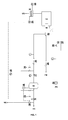
- a device for carrying out the method according to the invention which in the flowchart in Fig. 1 is shown with its essential functional elements, characterized in that it comprises an exhaust gas supply line (1), a natural gas supply line (2), an air supply line (3), one or more combustion chambers (7) with a burner connected thereto (6), an am Output of the combustion chamber installed catalytic purification stage (8) and has monitoring devices for the course of the combustion.
- a separate safety distance is provided for increasing the safety in the gas supply line for natural gas and the exhaust gas.
- the exhaust gas supply line is particularly preferably equipped with a gas buffer container (9), so that pressure and volume flow fluctuations in the exhaust gas stream to be cleaned can be compensated and not transferred to the burner (6). This ensures a more even combustion.
- the natural gas supply line (2) and the exhaust gas supply line (1) are brought together before entering the burner in a mixing chamber (33). Thereby, the mixing can be ensured even at higher inert gas in the exhaust gas.
- the burner is a blower burner with two fuel gas inlets. This allows the exhaust gas to be cleaned and the natural gas also supplied unmixed to the burner and only be mixed directly in the burner.
- the combustion air supply is preferably via a fan (in the air blower (34)) and / or via a valve (35) adjustable. Depending on the required flow rate, the control takes place via a valve or at higher throughputs via a fan. If necessary, both are adjustable for fine tuning.
- the monitoring devices are particularly preferably integrated into a total control with transducers. This enables efficient centralized control and monitoring.
- the components of the device are preferably transported separately as individual modules and can be built on site with connecting pipes and connections to the entire system.
- the connecting pipes are preferably equipped with a quick coupling system.
- the entire device can be transported as a compact unit in the build-up state. This makes it possible to make the emission control system quickly ready for use and, if necessary, to connect to an exhaust gas generating plant. Due to the compact design, this can also be done in confined spaces.
- the purified waste gas can be cooled by means of heat exchangers (not shown in the drawings) and the energy recovered from this via thermal oil and / or steam can be made available to other processes, since they are not suitable for preheating the exhaust gases to be cleaned is needed.
- the described method has several advantages: It allows very compact systems because of the small volume flows, since the admixture of air to the exhaust gas is eliminated. The air is first supplied to the burner, so that there is no explosive mixture before. Therefore, there are only minor requirements for explosion protection. Furthermore, this results in low system costs, low energy consumption and low maintenance costs. The operational readiness of the system can be achieved within a few minutes.
- the GNV works independently of the concentration of hydrocarbons in the exhaust gas.
- the exhaust gas laden with combustible components passes via the solenoid valve (11) into the gas buffer container (9).
- the exhaust gas supply line (1) has a diameter of 25 mm in this embodiment.
- the exhaust gas has a maximum temperature of about 50 ° C and a pressure of about 1.3 bar.
- a permanent oxygen analysis (15) is performed.
- the gas buffer (9) is used to compensate for pressure and volume fluctuations in the exhaust gas.
- a pressure monitoring by means of PS + pressure switch (18) on the gas buffer container (9) ensures that from reaching a certain minimum pressure by opening the solenoid valve (12), the exhaust gas to be cleaned the burner (6) is supplied.
- the gas pressure is reduced by a pressure reducer (25) and kept constant.
- a pressure reducer Before entering the burner (6) is mixed with an amount of natural gas, which is sufficient to ensure stable combustion.
- both gas strands Prior to mixing, which can take place either in a mixing chamber (33) or directly through a pipe junction depending on the gases contained and volume flows through, both gas strands each pass through their own safety fittings section consisting of a pressure switch and redundancy reasons two solenoid valves (27, 28 and 29 , 30).
- the quantities of gas introduced into the mixing chamber (33) or the burner (6) are controlled by motor valves (19, 20) which are connected to the exhaust gas line by means of the pressure switches PS- (31) and PS + (32) and the natural gas line via the temperature regulator ( 23) which is arranged at the inlet of the catalytic purification stage (8).
- the engine valve (19) thus additionally ensures that the pressure is kept constant in the range set at the pressure switches (31) and (32). Especially when opening the solenoid valves (27, 28) so peaks in the energy input into the burner can be avoided.
- a corresponding safety circuit allows the opening of the solenoid valves (27, 28) only when the engine valve (19) is in its minimum position.
- the necessary for the combustion of the exhaust gases (oxidation of impurities) combustion air is metered in via the air supply line (3).
- the amount of air is adjusted so that it supplies the oxygen in approximately stoichiometric amount for the combustion of the design gas mixture to be expected from natural gas and exhaust gas.
- the regulation of the air supply can also take place via the fan of the air blower (34).
- An automatically controlled supply of cooling air into the combustion chamber (7) takes place via the engine valve (21).
- the temperature controller (23) which measures the inlet temperature at the catalytic purification stage (8), controls the engine valves (20, 21) accordingly to ensure stable combustion and the required inlet temperature for the catalyst.
- the temperature switch (22) is mounted, which measures the temperature in the burner tube before mixing with the cooling air.
- the catalytic purification stage (8) adjoins the combustion chamber (7).
- the purified exhaust gas leaves the system via the outlet (5), which has a diameter of 200 mm, with a maximum pressure of approx. 1.05 bar and a maximum temperature of approx. 530 ° C. This can either be directly followed by a chimney or one or more heat exchangers for the recovery of heat energy for other processes, which is not shown in the drawing.
- the control process by the temperature controller (23) is carried out as follows: When commissioning the system, the amount of air calculated for the stoichiometric combustion of the exhaust gas / natural gas mixture is set at the valve (35). The engine valve (21) is adjusted so that a minimum amount of air in the burner (6) passes. Subsequently, the solenoid valves (29, 30) of the safety route are opened and the system initially operated in standby mode with natural gas. The engine valve (20) is accordingly fully open. If the predetermined minimum pressure is present at the gas buffer container (9) and the temperature at the inlet of the catalytic purification stage (8) has reached its minimum value, the solenoid valves (27, 28) of the exhaust gas line are opened and the system operates in the disposal mode.
- the temperature regulator (23) throttles the engine valve (20) in order to keep the inlet temperature at the catalyst in the intended range. If the engine valve (20) reaches its minimum position and the temperature in the combustion chamber (7) is still too high, then the temperature controller (23) also controls the engine valve (21) and thus opens the cooling air supply into the combustion chamber (7). If the content of combustible constituents in the exhaust gas and thus the temperature in the combustion chamber decreases, the temperature regulator (23) restricts the engine valve (20) again and optionally further opens the natural gas supply via the engine valve (20).
- the temperature switch (24) is mounted at the outlet of the catalytic purification stage (8), which monitors the maximum operating temperature of the catalyst. If this temperature is exceeded, the temperature switch (24) triggers the emergency shutdown of the system by closing the solenoid valves (11, 12) and opening the solenoid valve (10). The exhaust gas is then safely discharged through the emergency outlet via roof (4).
- the catalyst used in the catalytic purification stage (8) is an oxidation catalyst, which in this example consists of a 1: 1 mixture of palladium and platinum, in an amount of 40 g / ft 3 on a carrier made of cordierite honeycomb applied with 100 cpsi.
Abstract
Description
Die vorliegende Erfindung betrifft ein Verfahren zur Reinigung von Abgasen durch generative Nachverbrennung. Ein sauerstofffreies Abgas mit brennbaren Verunreinigungen, wie es beispielsweise in Härtereien anfällt, wird dabei ohne vorherige Erhitzung oder Wärmetausch in einer Brennkammer verbrannt und das resultierende Abgas anschließend in einer katalytischen Reinigungsstufe nachgereinigt. Ferner wird eine Vorrichtung zur Durchführung des Verfahrens vorgestellt.The present invention relates to a method for purifying exhaust gases by generative afterburning. An oxygen-free exhaust gas with combustible impurities, such as occurs in hardening shops, is incinerated without prior heating or heat exchange in a combustion chamber and the resulting exhaust subsequently cleaned in a catalytic purification stage. Furthermore, an apparatus for carrying out the method is presented.
Im Stand der Technik ist zur Reinigung von Abgasen, die brennbare Verunreinigungen wie Kohlenwasserstoffe oder Wasserstoff enthalten, eine Reihe von Verfahren bekannt. Im Sinne dieser Anmeldung ist unter dem Begriff "Abgas" nicht nur das Abgas einer Verbrennung, sondern auch eine schadstoffbeladene Abluft aus Anlagen zu verstehen.In the prior art, a number of methods are known for purifying exhaust gases containing combustible impurities such as hydrocarbons or hydrogen. For the purposes of this application, the term "exhaust gas" is to be understood as meaning not only the exhaust gas of a combustion but also a pollutant-laden exhaust air from installations.
Das einfachste Verfahren ist die Verbrennung in einer Fackel. Hierbei werden die zu reinigenden Abgase einer offenen Flamme zugeführt und die zündfähigen Bestandteile dort verbrannt. Dieses Verfahren zeichnet sich durch eine einfache und kostengünstige Vorrichtung aus, die bei der Inbetriebnahme schnell Betriebsbereitschaft erreicht. Allerdings stehen dem die Nachteile gegenüber, dass das Abgas zündfähig sein muss, das Verfahren nicht regelbar ist und die Einhaltung der Grenzwerte für Schadstoffe im Abgas nicht immer gewährleistet ist.The simplest method is burning in a torch. Here, the exhaust gases to be cleaned are fed to an open flame and burned the ignitable components there. This method is characterized by a simple and inexpensive device that quickly reaches operational readiness during commissioning. However, this is offset by the disadvantages that the exhaust gas must be ignitable, the process is not regulated and compliance with the limit values for pollutants in the exhaust gas is not always guaranteed.
Eine Verbesserung des Verfahrens stellt das als Thermische Nachverbrennung (TNV) bekannte Verfahren dar. Hierbei werden die Abgase je nach der Zusammensetzung der zu entfernenden Bestandteile auf Temperaturen von 750-1000 °C erhitzt und in einer Brennkammer verbrannt. Zur Einhaltung der Vorschriften des Explosionsschutzes müssen die Abgase dazu vorher mit soviel Luft verdünnt werden, dass eine Konzentration der brennbaren Bestandteile von unter 25% der unteren Explosionsgrenze sichergestellt wird. Da die Verbrennung in einem einfachen Brenner erfolgt, handelt es sich auch bei der TNV um ein Verfahren mit einer einfachen Vorrichtung. Die Kohlenwasserstoffe des Abgases werden sicher umgesetzt und die Grenzwerte für Schadstoffe im Abgas damit zuverlässig eingehalten. Auch bei diesem System wird die Betriebsbereitschaft schnell erreicht. Die TNV hat jedoch das Manko eines sehr hohen Energieverbrauchs, da durch die große Menge an zugesetzter Luft eine erheblich größere Gasmenge als das ursprüngliche Abgas auf sehr hohe Temperaturen zu erhitzen ist. Durch nachgeschaltete Wärmetauscher, die das Abgas wiederum vor Eintritt in den Brennraum vorheizen können, kann der Wirkungsgrad zwar verbessert werden, da die Vorheizung aber nur so hoch erfolgen darf, dass noch keine Reaktion im Wärmetauscher erfolgt, ist trotzdem noch ein erheblicher Energiebedarf aufzuwenden. Ebenso sind die Herstellungskosten einer TNV Anlage höher, da aufgrund der hohen Prozesstemperaturen höhere Materialkosten anfallen (z. B. für hochtemperaturfeste Stähle). Zusätzlich ergibt sich ein größerer Aufwand durch die Notwendigkeit des Einsatzes von explosionsgeschützten Armaturen.An improvement of the method is known as thermal afterburning (TNV) method. Here, the exhaust gases are heated depending on the composition of the components to be removed to temperatures of 750-1000 ° C and burned in a combustion chamber. To comply with explosion protection regulations, the exhaust gases must first be diluted with enough air to ensure that the concentration of the combustible components remains constant of less than 25% of the lower explosive limit. Since the combustion takes place in a simple burner, the TNV is also a simple device. The hydrocarbons of the exhaust gas are safely converted and the limits for pollutants in the exhaust gas thus reliably maintained. Also in this system, the operational readiness is reached quickly. However, the TNV has the drawback of a very high energy consumption, since the large amount of added air to heat a much larger amount of gas than the original exhaust gas to very high temperatures. By downstream heat exchanger, which in turn can preheat the exhaust gas before entering the combustion chamber, the efficiency can be improved, but since the preheating may only be so high that no reaction takes place in the heat exchanger, is still a considerable amount of energy to spend. Likewise, the production costs of a TNV plant are higher, as higher material costs are incurred due to the high process temperatures (eg for high temperature resistant steels). In addition, there is a greater effort by the need for the use of explosion-proof valves.
Beispielhaft für die unzähligen in der Fach- und Patentliteratur beschriebenen thermischen Nachverbrennungsanlagen seien hier
Eine Weiterentwicklung der TNV ist die Katalytische Nachverbrennung (KNV). Hierbei wird durch den Einsatz einer katalytischen Reinigungsstufe die für den sicheren Umsatz der Kohlenwasserstoffe benötigte Temperatur abgesenkt. Abhängig von den zu entfernenden Abgasbestandteilen und dem eingesetzten Katalysator wird das zu reinigende Abgas mit Hilfe von Wärmetauschern und gegebenenfalls einer Zusatzheizung oder eines Zusatzbrenners auf 250-400 °C erhitzt. Auch hier muss zur Einhaltung der Vorschriften des Explosionsschutzes wieder eine Verdünnung der zugeführten Abgase mit Luft auf eine Konzentration der brennbaren Bestandteile von unter 25% der unteren Explosionsgrenze erfolgen. Die Vorteile der KNV sind dieselben wie die der TNV, wobei der Energieeinsatz deutlich geringer ist. Durch nachgeschaltete Wärmetauscher und Rückgewinnung der Reaktionswärme kann sogar ein autothermer Betrieb der Anlage erreicht werden. Nachteilig ist jedoch, dass die erzeugten Abluftmengen genauso hoch sind wie bei der TNV, wodurch gerade bei zu erwartenden Konzentrationsspitzen von Kohlenwasserstoffen im Abgas ein recht hoher Energieeinsatz nötig ist. Zudem ist ein autothermer Betrieb nur ab mittleren Kohlenwasserstoffkonzentrationen möglich. Darunter ist eine Stützfeuerung mit zusätzlichen Abgasen oder eine Zusatzheizung nötig. Ein weiterer Nachteil ist die Empfindlichkeit des Katalysators gegen bestimmte Katalysatorgifte, wie z. B. Halogene, Silikone, Phosphor, Schwefel und Schwermetalle, die sicher aus dem zu reinigenden Abgas ausgeschlossen sein müssen. Ferner ist der Umsetzungsgrad an dem Katalysatorbett etwas geringer als bei der TNV.An advancement of the TNV is the catalytic afterburning (KNV). In this case, the temperature required for the safe conversion of the hydrocarbons is lowered by the use of a catalytic purification stage. Depending on the exhaust components to be removed and the catalyst used, the exhaust gas to be cleaned is heated to 250-400 ° C. with the aid of heat exchangers and optionally an auxiliary heater or an additional burner. Again, to comply with the requirements of explosion protection, dilution of the supplied exhaust gases with air to a concentration of the combustible constituents of less than 25% of the lower explosion limit must be carried out again. The advantages of the KNV are the same as those of the TNV, whereby the energy consumption is significantly lower. By downstream heat exchanger and recovery of the heat of reaction can even be achieved autothermal operation of the system. The disadvantage, however, is that the amounts of exhaust air generated are just as high as in the TNV, whereby a fairly high energy input is necessary especially in the case of expected concentration peaks of hydrocarbons in the exhaust gas. In addition, an autothermal operation is possible only from average hydrocarbon concentrations. Below is a support fire with additional exhaust or additional heating necessary. Another disadvantage is the sensitivity of the catalyst to certain catalyst poisons, such as. As halogens, silicones, phosphorus, sulfur and heavy metals, which must be safely excluded from the exhaust gas to be cleaned. Furthermore, the degree of conversion at the catalyst bed is somewhat lower than in the TNV.
Die Regenerative Nachverbrennung (RNV) stellt eine TNV oder KNV mit einer "integrierten" Wärmerückgewinnung dar. Dabei wird der Wärmeinhalt des gereinigten Abgases in einer Wärmespeichermasse, die sich direkt in der Oxidationszone befindet, gespeichert und steht damit dem Oxidationsprozess unmittelbar zur Verfügung. In der Regel werden dafür keramische Füllkörper-Schüttungen verwendet, die bei geringem Druckverlust einen guten Wirkungsgrad des Wärmeübergangs ermöglichen. Im Fall der thermischen Nachverbrennung ist die Schüttung mit inertem Schüttgut gefüllt, während die katalytische Nachverbrennungsanlage mit einer entsprechenden Katalysatorfüllung beschickt ist. Mindestens zwei solcher Schüttungen werden im zyklischen Wechsel betrieben, wobei die eine heiße Schüttung zur Vorwärmung des Abgases von diesem durchströmt wird und dabei abkühlt und die zweite kalte Schüttung durch die Oxidation der Abgase aufgeheizt wird. Der Sauerstoff in der Kühlluft, die im Katalysator zugeführt wird, nimmt hierbei an der Reaktion teil. Durch die gute Wärmerückgewinnung innerhalb der Anlage kann bei katalytischen Systemen schon bei geringen Konzentrationen an Kohlenwasserstoffen eine autotherme Betriebsweise erzielt werden. Dieser Vorteil ist allerdings mit einem hohen apparativen Aufwand mit entsprechend großem Platzbedarf verbunden. Zudem bedingt der Einsatz von Ventilen, die heiße Gase sperren, einen erhöhten Wartungsaufwand. Aufgrund der langen Aufheizzeit, die die Wärmespeicher benötigen, wird die Betriebsbereitschaft einer solchen Anlage nur langsam erreicht. Daher sind diese Anlagen für einen sporadischen oder kurzzeitigen Einsatz ungeeignet und nur im Dauerbetrieb sinnvoll einsetzbar.Regenerative afterburning (RNV) is a TNV or KNV with "integrated" heat recovery. In this process, the heat content of the purified waste gas is stored in a heat storage mass that is located directly in the oxidation zone and is therefore directly involved in the oxidation process to disposal. As a rule, ceramic packed beds are used for this, which enable a good efficiency of heat transfer with low pressure loss. In the case of thermal afterburning, the bed is filled with inert bulk material while the catalytic afterburning unit is charged with an appropriate catalyst charge. At least two such beds are operated in cyclic alternation, wherein a hot bed for preheating the exhaust gas is flowed through by this and thereby cools and the second cold bed is heated by the oxidation of the exhaust gases. The oxygen in the cooling air, which is supplied in the catalyst, in this case participates in the reaction. Due to the good heat recovery within the system, an autothermal mode of operation can be achieved in catalytic systems even at low concentrations of hydrocarbons. However, this advantage is associated with a high expenditure on equipment with a correspondingly large space requirement. In addition, the use of valves that lock hot gases, requires increased maintenance. Due to the long heat-up time, which require the heat storage, the operational readiness of such a system is reached only slowly. Therefore, these systems are unsuitable for sporadic or short-term use and useful only in continuous operation.
Ein Beispiel für die Regenerative Nachverbrennung findet sich in der
Aus den geschilderten Nachteilen der im Stand der Technik bekannten Abgas- und Abluftreinigungsverfahren ergibt sich die Aufgabe der vorliegenden Erfindung darin, ein Verfahren zur Abgasreinigung zur Verfügung zu stellen, das bei kompakter Bauweise mit geringem Platzbedarf unter möglichst geringem Energieeinsatz eine Reinigung von sauerstofffreien Abgasen mit sehr hohen Konzentrationen an brennbaren Bestandteilen ermöglicht, wie sie beispielsweise in Abgasen von Härtereien anfallen. Die Konzentration an brennbaren Bestandteilen kann bei diesen bis zu 100 Vol.-% betragen. Im Sinne der Erfindung sind unter sauerstofffreien Abgasen solche Abgase zu verstehen, die keinen Sauerstoff enthalten, was durch eine permanente Sauerstoffanalyse sichergestellt wird.From the disadvantages of the known in the art exhaust and Abluftreinigungsverfahren the object of the present invention is to provide a method for exhaust gas cleaning available, the cleaning of oxygen-free exhaust gases in a compact design with low space requirements with minimal energy consumption high concentrations of combustible components, such as those incurred in exhaust gases from hardening shops. The concentration of combustible constituents can be up to 100% by volume in these. For the purposes of the invention, oxygen-free exhaust gases are to be understood as those exhaust gases which contain no oxygen, which is ensured by a permanent oxygen analysis.
Gelöst wird die Aufgabe durch das erfindungsgemäße Verfahren zur Reinigung von sauerstofffreien Abgasen durch generative Nachverbrennung, wobei die Abgase Anteile an brennbaren Bestandteilen von bis zu 100% aufweisen und der Energieinhalt der Abgase direkt zur Erhitzung der Abgase eingesetzt wird, beinhaltend die Schritte
- a. Zuführen der zu reinigenden Abgase;
- b. Ausgleichen von Druck- und Mengenschwankungen in den zu reinigenden Abgasen;
- c. Mischen eines ersten Gasstroms, bestehend aus den zu reinigenden Abgasen, derart mit einem zweiten Gasstrom, bestehend aus Erdgas, wobei die zugemischte Menge an Erdgas abhängig ist vom Gehalt der brennbaren Bestandteile in den Abgasen und ausreichend ist, um eine stabile Verbrennung zu gewährleisten;
- d. Einleiten der gemischten Gasströme und eines dritten Gasstroms bestehend aus Verbrennungsluft in einen Brenner wenigstens einer Brennkammer;
- e. Verbrennung der vereinigten Gasströme in der Brennkammer bei so hohen Temperaturen, dass unerwünschte, brennbare Gasbestandteile durch Oxidation entfernt werden, wobei die bei der Oxidation aus dem Energieinhalt der Abgase gewonnene Wärmeenergie direkt zur Erhitzung der Abgase eingesetzt wird;
- f. Katalytische Reinigung der oxidierten Abgase zur Umsetzung darin verbliebener Verunreinigungen in einer katalytischen Reinigungsstufe am Ausgang der Brennkammer;
- g. Einleiten von Kühlluft in die Brennkammer zum Einstellen der erforderlichen Temperatur für die katalytische Reinigung in der katalytischen Reinigungsstufe.
- a. Supplying the exhaust gases to be cleaned;
- b. Compensation of pressure and volume fluctuations in the exhaust gases to be cleaned;
- c. Mixing a first gas stream, consisting of the exhaust gases to be cleaned, so with a second gas stream consisting of natural gas, wherein the added amount of natural gas is dependent on the content of the combustible components in the exhaust gases and sufficient to ensure a stable combustion;
- d. Introducing the mixed gas streams and a third gas stream consisting of combustion air into a burner of at least one combustion chamber;
- e. Combustion of the combined gas streams in the combustion chamber at such high temperatures that unwanted, combustible gas constituents are removed by oxidation, which in the oxidation of the energy content of the exhaust gases obtained heat energy is used directly for heating the exhaust gases;
- f. Catalytic purification of the oxidized exhaust gases to react therein residual impurities in a catalytic purification stage at the exit of the combustion chamber;
- G. Introducing cooling air into the combustion chamber to adjust the required temperature for the catalytic purification in the catalytic purification stage.
Die zu behandelnden Abgase können zu 100 Vol.-% aus brennbaren Bestandteilen bestehen, enthalten in einer bevorzugten Ausführungsform der Erfindung jedoch mindestens 0 Vol.-%, bevorzugt mindestens 10 Vol.-%, besonders bevorzugt mindestens 20 Vol.-% brennbare Anteile.The exhaust gases to be treated may consist of 100 vol .-% of combustible constituents, contain in a preferred embodiment of the invention, however, at least 0 vol .-%, preferably at least 10 vol .-%, more preferably at least 20 vol .-% combustible fractions.
Ist der Anteil der brennbaren Gase im Abgas kleiner als 100 Vol.-%, so werden die Abgase vor der Verbrennung im Brenner mit Erdgas vermischt, um die Oxidation zu fördern. Die Menge des zugemischten Erdgases ist dabei abhängig vom Gehalt der brennbaren Anteile im Abgas.If the proportion of combustible gases in the exhaust gas is less than 100% by volume, the exhaust gases are mixed with natural gas before combustion in the burner in order to promote oxidation. The amount of natural gas added depends on the content of the combustible components in the exhaust gas.
Besonders bevorzugt erfolgt die Zumischung des Erdgases mittels einer automatischen Regelung, die sicherstellt, dass im Brennraum eine Temperatur aufrecht erhalten wird, die hoch genug für die nachfolgende katalytische Reinigungsstufe ist. Ebenso erfolgt bevorzugt eine automatische Regelung der Kühlluftzufuhr in den Brennraum, über die die Temperatur unterhalb des Maximums gehalten werden kann, das der maximalen Arbeitstemperatur des Katalysators entspricht.Particularly preferably, the addition of the natural gas by means of an automatic control, which ensures that a temperature is maintained in the combustion chamber, which is high enough for the subsequent catalytic purification stage. Likewise, preferably, an automatic control of the cooling air supply into the combustion chamber, via which the temperature can be kept below the maximum, which corresponds to the maximum operating temperature of the catalyst.
Die Flammentemperatur des Brenners wird bevorzugt im Bereich von 600-1200 °C, besonders bevorzugt im Bereich von 800-1000 °C, gehalten. Die katalytische Reinigungsstufe wird bevorzugt bei 300-650 °C, besonders bevorzugt bei 400-530 °C betrieben.The flame temperature of the burner is preferably maintained in the range of 600-1200 ° C, more preferably in the range of 800-1000 ° C. The catalytic purification stage is preferably operated at 300-650 ° C., more preferably at 400-530 ° C.
In einer besonders bevorzugten Ausführungsform erfolgt die Regelung der Erdgaszufuhr in den Brenner in Abhängigkeit von der Temperatur in der Brennkammer und/oder der Temperatur am Eintritt in den Katalysator. Sinkt bei konstanter Zufuhr von Verbrennungsluft und Kühlluft die Temperatur im Brennraum oder am Katalysatoreintritt ab, so wird die Erdgaszufuhr erhöht, weil weniger brennbare Bestandteile im Abgas vorhanden sind. Steigt die Temperatur an, wird entsprechend weniger Erdgas zugemischt.In a particularly preferred embodiment, the regulation of the natural gas supply into the burner takes place as a function of the temperature in the combustion chamber and / or the temperature at the inlet into the catalyst. Decreases at a constant supply of combustion air and cooling air, the temperature in the combustion chamber or at the catalyst inlet, the natural gas supply is increased because less combustible components are present in the exhaust gas. If the temperature rises, less natural gas is added accordingly.
Eine Vorrichtung zur Durchführung des erfindungsgemäßen Verfahrens, die im Fließschema in
In einer bevorzugten Ausführungsvariante ist zur Erhöhung der Sicherheit in der Gaszufuhrleitung für Erdgas und das Abgas jeweils eine eigene Sicherheitsstrecke vorgesehen.In a preferred embodiment, a separate safety distance is provided for increasing the safety in the gas supply line for natural gas and the exhaust gas.
Die Abgaszufuhrleitung ist besonders bevorzugt mit einem Gaspufferbehälter (9) ausgestattet, damit Druck- und Volumenstromschwankungen im zu reinigenden Abgasstrom ausgeglichen werden können und nicht auf den Brenner (6) übertragen werden. Dadurch wird eine gleichmäßigere Verbrennung gewährleistet.The exhaust gas supply line is particularly preferably equipped with a gas buffer container (9), so that pressure and volume flow fluctuations in the exhaust gas stream to be cleaned can be compensated and not transferred to the burner (6). This ensures a more even combustion.
In einer weiteren bevorzugten Ausgestaltungsform werden die Erdgaszufuhrleitung (2) und die Abgaszufuhrleitung (1) vor Eintritt in den Brenner in einer Mischkammer (33) zusammengeführt. Dadurch kann die Vermischung auch bei höheren Inertgasanteilen im Abgas sichergestellt werden.In a further preferred embodiment, the natural gas supply line (2) and the exhaust gas supply line (1) are brought together before entering the burner in a mixing chamber (33). Thereby, the mixing can be ensured even at higher inert gas in the exhaust gas.
In einer weiteren Ausführungsform ist der Brenner ein Gebläsebrenner mit zwei Brenngaseingängen. Dadurch können das zu reinigende Abgas und das Erdgas auch unvermischt dem Brenner zugeführt und erst unmittelbar im Brenner vermischt werden.In another embodiment, the burner is a blower burner with two fuel gas inlets. This allows the exhaust gas to be cleaned and the natural gas also supplied unmixed to the burner and only be mixed directly in the burner.
Die Verbrennungsluftzufuhr ist bevorzugt über einen Ventilator (im Luftgebläse (34)) und/oder über ein Ventil (35) regelbar. Je nach benötigter Durchflussmenge erfolgt die Regelung über ein Ventil oder bei höheren Durchsätzen über einen Ventilator. Zur Feinabstimmung sind gegebenenfalls beide regelbar.The combustion air supply is preferably via a fan (in the air blower (34)) and / or via a valve (35) adjustable. Depending on the required flow rate, the control takes place via a valve or at higher throughputs via a fan. If necessary, both are adjustable for fine tuning.
Die Überwachungseinrichtungen sind besonders bevorzugt in eine Gesamtsteuerung mit Messwertaufnehmern integriert. Auf diese Weise wird eine effiziente zentrale Steuerung und Überwachung ermöglicht.The monitoring devices are particularly preferably integrated into a total control with transducers. This enables efficient centralized control and monitoring.
Die Bestandteile der Vorrichtung sind bevorzugt als Einzelmodule getrennt transportierbar und am Einsatzort mit verbindenden Rohrleitungen und Anschlüssen zur Gesamtanlage aufbaubar. Dazu sind die verbindenden Rohrleitungen entsprechend bevorzugt mit einem Schnellkupplungssystem ausgestattet.The components of the device are preferably transported separately as individual modules and can be built on site with connecting pipes and connections to the entire system. For this purpose, the connecting pipes are preferably equipped with a quick coupling system.
In einer besonders bevorzugten Ausführungsform ist die gesamte Vorrichtung als kompakte Einheit im Aufbauzustand transportierbar. Dadurch ist es möglich, die Abgasreinigungsanlage schnell einsatzbereit zu machen und bei Bedarf an eine Abgas erzeugende Anlage anzuschließen. Durch die kompakte Bauweise kann dies auch bei beengten Platzverhältnissen erfolgen.In a particularly preferred embodiment, the entire device can be transported as a compact unit in the build-up state. This makes it possible to make the emission control system quickly ready for use and, if necessary, to connect to an exhaust gas generating plant. Due to the compact design, this can also be done in confined spaces.
Durch die modulare Bauweise können in weiteren Ausführungsformen auch mehrere Abgas erzeugende Anlagen mit ihren Abgaszufuhrleitungen (1) an einen entsprechend dimensionierten Brenner (6) angeschlossen werden. Ferner können auch die Abgase mehrerer Brennkammern (7) einer entsprechend dimensionierten gemeinsamen katalytischen Reinigungsstufe (8) zugeführt werden. Dadurch lässt sich das Anlagenkonzept flexibel den örtlichen Gegebenheiten anpassen und durch gemeinsam genutzte Anlagenteile weiterer Platz einsparen.Due to the modular design, in several embodiments, several exhaust gas generating plants with their exhaust gas supply lines (1) to a correspondingly sized burner (6) can be connected. Furthermore, the exhaust gases of several combustion chambers (7) of a correspondingly dimensioned common catalytic purification stage (8) can be supplied. As a result, the system concept can be flexibly adapted to local conditions and further space can be saved through shared system components.
Bei den im Stand der Technik beschriebenen Verfahren muss in der Regel aus Gründen des Explosionsschutzes eine Verdünnung der zu reinigenden Abgase mit Luft auf eine Konzentration der brennbaren Bestandteile von unter 25% der unteren Explosionsgrenze erfolgen. Dadurch bedingt müssen sehr große Mengen an Gasen transportiert und erhitzt werden. Diese Verfahren sind daher für Abgase mit sehr hohen Anteilen an brennbaren Gasen eher ungeeignet. Die vorliegende Erfindung ist im Gegensatz dazu besonders auf solche Abgase mit hohen Anteilen an brennbaren Gasen von bis zu 100% ausgerichtet. Solche Abgase kommen z. B. in Härtereien in der metallbearbeitenden Industrie vor, die Werkstücke unter Ausschluss von Luft unter Einsatz von Kohlenwasserstoffen in geschlossenen Öfen härten. Eine Abgasreinigung solcher Abgase findet derzeit noch nicht statt.In the methods described in the prior art usually for reasons of explosion protection, a dilution of the exhaust gases to be cleaned with air to a concentration of the combustible components of less than 25% of the lower explosion limit. As a result, very large quantities of gases have to be transported and heated. These methods are therefore rather unsuitable for exhaust gases with very high levels of combustible gases. By contrast, the present invention is particularly directed to such exhaust gases with high levels of combustible gases of up to 100%. Such exhaust gases come z. As in hardening shops in the metalworking industry, the workpieces cure in the absence of air using hydrocarbons in closed furnaces. An exhaust gas purification of such exhaust gases is currently not taking place.
Durch die Beschränkung auf derartige sauerstofffreie Abgase und den Verzicht auf eine Vorerwärmung der Abgase, sind die Anforderungen an den Explosionsschutz wesentlich geringer. Die zu transportierenden Gasmengen bleiben vorteilhaft klein und die Erhitzung der Abgase auf die in der katalytischen Reinigungsstufe (8) benötigten Temperaturen erfolgt überwiegend durch die aufgrund der hohen Konzentrationen an brennbaren Gasbestandteilen hohe Verbrennungswärme des Abgases. Luft wird hierfür nur in annähernd stöchiometrischer Menge für die Verbrennung zugeführt. Sinkt der Anteil der brennbaren Bestandteile im Abgas, so wird bei Bedarf Erdgas zugemischt, um konstante Verbrennungstemperaturen zu gewährleisten. Der wesentliche Unterschied zu den bekannten Verfahren mit Wärmerückgewinnung liegt darin, dass der Energieinhalt des Abgases direkt zur Erwärmung genutzt wird. Daher wird das Verfahren der vorliegenden Erfindung auch im Gegensatz zur Regenerativen Nachverbrennung als "Generative Nachverbrennung" (GNV) bezeichnet.Due to the restriction to such oxygen-free exhaust gases and the absence of preheating the exhaust gases, the requirements for explosion protection are much lower. The quantities of gas to be transported advantageously remain small and the heating of the exhaust gases to the temperatures required in the catalytic purification stage (8) is predominantly due to the high heat of combustion of the exhaust gas due to the high concentrations of combustible gas constituents. Air is supplied for this purpose only in approximately stoichiometric amount for the combustion. If the proportion of flammable components in the exhaust gas decreases, natural gas is mixed in if necessary to ensure constant combustion temperatures. The essential difference to the known methods with heat recovery is that the energy content of the exhaust gas is used directly for heating. Therefore, the method of the present invention is also referred to as "generative afterburning" (GNV), in contrast to regenerative afterburning.
Im Brenner (6) werden alle unter den gegebenen Bedingungen brennbaren Abgase verbrannt. Dadurch werden etwa 98% der Verunreinigungen aus dem Abgas entfernt. Zur weiteren Reinigung schließt sich dann eine katalytische Reinigungsstufe (8) an. Durch eine geregelte Beimischung von Kühlluft in den Brennraum wird die Prozesstemperatur für die nachfolgende katalytische Reinigung eingestellt. Daher ist es möglich, die Flammentemperatur im Brenner bei so hohen Temperaturen zu halten, dass schon dort ein Großteil der Verunreinigungen verbrennt. Die katalytische Nachreinigung sorgt dann für eine vollständige Umsetzung der Kohlenwasserstoffe, die im Brenner nicht bzw. unvollständig umgesetzt wurden. Nach Verlassen der Katalysatorstufe über den Auslass (5) kann das gereinigte Abgas über Wärmetauscher (in den Zeichnungen nicht dargestellt) abgekühlt werden und die dabei zurück gewonnene Energie über Thermalöl und/oder Dampf anderen Prozessen zur Verfügung gestellt werden, da sie nicht für die Vorheizung der zu reinigenden Abgase benötigt wird.In the burner (6) all flammable under the given conditions flammable gases are burned. As a result, about 98% of the impurities are removed from the exhaust gas. For further purification then joins a catalytic purification stage (8). By a controlled admixture of cooling air into the combustion chamber, the process temperature for the subsequent catalytic purification set. Therefore, it is possible to keep the flame temperature in the burner at such high temperatures that there already burns a large part of the impurities. The catalytic post-purification then ensures complete conversion of the hydrocarbons, which were not or incompletely reacted in the burner. After leaving the catalyst stage via the outlet (5), the purified waste gas can be cooled by means of heat exchangers (not shown in the drawings) and the energy recovered from this via thermal oil and / or steam can be made available to other processes, since they are not suitable for preheating the exhaust gases to be cleaned is needed.
Durch das beschriebene Verfahren ergeben sich mehrere Vorteile: Es ermöglicht sehr kompakte Anlagen wegen der kleinen Volumenströme, da die Beimischung von Luft zum Abgas entfällt. Die Luft wird erst dem Brenner zugeführt, so dass vorher kein zündfähiges Gemisch vorliegt. Daher gibt es nur geringe Anforderungen an den Explosionsschutz. Ferner ergeben sich dadurch geringe Anlagenkosten, geringer Energieverbrauch und geringe Wartungskosten. Die Betriebsbereitschaft der Anlage kann innerhalb weniger Minuten hergestellt werden. Die GNV arbeitet unabhängig von der Konzentration der Kohlenwasserstoffe im Abgas.The described method has several advantages: It allows very compact systems because of the small volume flows, since the admixture of air to the exhaust gas is eliminated. The air is first supplied to the burner, so that there is no explosive mixture before. Therefore, there are only minor requirements for explosion protection. Furthermore, this results in low system costs, low energy consumption and low maintenance costs. The operational readiness of the system can be achieved within a few minutes. The GNV works independently of the concentration of hydrocarbons in the exhaust gas.
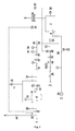
Im Folgenden soll das vorgestellte Verfahren anhand des Fließschemas einer Anlage in vorteilhafter Ausgestaltung in
Über die Abgaszufuhrleitung (1) gelangt das mit brennbaren Bestandteilen beladene Abgas über das Magnetventil (11) in den Gaspufferbehälter (9). Die Abgaszufuhrleitung (1) besitzt in diesem Ausführungsbeispiel einen Durchmesser von 25 mm. Das Abgas hat eine maximale Temperatur von ca. 50 °C und einen Druck von ca. 1,3 bar. Um sicher zu stellen, dass kein Sauerstoff im Abgas vorhanden ist, wird eine permanente Sauerstoffanalyse (15) durchgeführt. Der Gaspuffer (9) dient dem Ausgleich von Druck- und Mengenschwankungen im Abgas. Eine Drucküberwachung mittels PS+ Druckschalter (18) am Gaspufferbehälter (9) sorgt dafür, dass ab dem Erreichen eines gewissen Mindestdrucks durch das Öffnen des Magnetventils (12) das zu reinigende Abgas dem Brenner (6) zugeführt wird. Bei Überschreiten eines Maximaldruckes wird der Überdruck dadurch abgebaut, dass das Magnetventil (10) geöffnet und das Abgas direkt durch den Notauslass über Dach (4) abgeleitet wird. Die entsprechende Auslassleitung ist mit einem Rückschlagventil (16) gesichert. Da der Gaspufferbehälter (9) beim ersten Anfahren der Anlage nach dem Aufbau noch mit Luft gefüllt ist, ist vor dem Gaspufferbehälter (9) eine Spülgaszufuhrleitung (13) mit manuellem Einlassventil für ein sauerstofffreies Spülgas, in der Regel Stickstoff, angebracht. Der entsprechende Spülgasauslass (14) mit manuellem Auslassventil ist nach dem manuellen Druckregelventil (17) hinter dem Magnetventil (12), das der Gewährleistung konstanter Druckbedingungen für den Brenner (6) dient, angeordnet. Somit kann man beim ersten Anfahren der Anlage vor der Einleitung des zu reinigenden Abgases zunächst manuell eine Spülung des Gaspufferbehälters (9) und seiner Zu- und Ableitungen durchführen, um die Sauerstofffreiheit und damit den Explosionsschutz herzustellen.Via the exhaust gas supply line (1), the exhaust gas laden with combustible components passes via the solenoid valve (11) into the gas buffer container (9). The exhaust gas supply line (1) has a diameter of 25 mm in this embodiment. The exhaust gas has a maximum temperature of about 50 ° C and a pressure of about 1.3 bar. To ensure that there is no oxygen in the exhaust gas, a permanent oxygen analysis (15) is performed. The gas buffer (9) is used to compensate for pressure and volume fluctuations in the exhaust gas. A pressure monitoring by means of PS + pressure switch (18) on the gas buffer container (9) ensures that from reaching a certain minimum pressure by opening the solenoid valve (12), the exhaust gas to be cleaned the burner (6) is supplied. When a maximum pressure is exceeded, the excess pressure is reduced by opening the solenoid valve (10) and discharging the exhaust gas directly through the emergency outlet via the roof (4). The corresponding outlet line is secured with a check valve (16). Since the gas buffer container (9) after initial construction of the system is still filled with air, in front of the gas buffer container (9) is a purge gas supply line (13) with a manual inlet valve for an oxygen-free purge gas, usually nitrogen attached. The corresponding Spülgasauslass (14) with manual outlet valve is after the manual pressure control valve (17) behind the solenoid valve (12), which is the guarantee of constant pressure conditions for the burner (6) arranged. Thus, you can first manually rinse the gas buffer tank (9) and its inlets and outlets perform at the first startup of the system before the introduction of the exhaust gas to be cleaned to produce the oxygen-free and thus the explosion protection.
Vor der Einspeisung in den Brenner (6) wird der Gasdruck über einen Druckminderer (25) reduziert und konstant gehalten. Vor dem Eintritt in den Brenner (6) erfolgt eine Vermischung mit einer Menge an Erdgas, die ausreichend ist, um eine stabile Verbrennung zu gewährleisten. Vor der Vermischung, die je nach enthaltenen Gasen und durchgesetzten Volumenströmen entweder in einer Mischkammer (33) oder direkt durch eine Rohrzusammenführung erfolgen kann, durchlaufen beide Gasstränge jeweils eine eigene Sicherheitsarmaturenstrecke, die aus einem Druckschalter und aus Redundanzgründen zwei Magnetventilen (27, 28 und 29, 30) besteht.Before being fed into the burner (6), the gas pressure is reduced by a pressure reducer (25) and kept constant. Before entering the burner (6) is mixed with an amount of natural gas, which is sufficient to ensure stable combustion. Prior to mixing, which can take place either in a mixing chamber (33) or directly through a pipe junction depending on the gases contained and volume flows through, both gas strands each pass through their own safety fittings section consisting of a pressure switch and redundancy reasons two solenoid valves (27, 28 and 29 , 30).
Die in die Mischkammer (33) oder den Brenner (6) eingelassenen Gasmengen werden durch Motorventile (19, 20) kontrolliert, die bei der Abgasstrecke mittels der Druckschalter PS- (31) und PS+ (32) und bei der Erdgasstrecke über den Temperaturregler (23), der am Eingang der katalytischen Reinigungsstufe (8) angeordnet ist, angesteuert werden. Das Motorventil (19) sorgt so zusätzlich dafür, dass der Druck konstant im Bereich, der an den Druckschaltern (31) und (32) eingestellt ist, gehalten wird. Besonders beim Öffnen der Magnetventile (27, 28) können so Spitzen im Energieeintrag in den Brenner vermieden werden. Eine entsprechende Sicherheitsschaltung gestattet die Öffnung der Magnetventile (27, 28) nur, wenn sich das Motorventil (19) in seiner Minimalposition befindet.The quantities of gas introduced into the mixing chamber (33) or the burner (6) are controlled by motor valves (19, 20) which are connected to the exhaust gas line by means of the pressure switches PS- (31) and PS + (32) and the natural gas line via the temperature regulator ( 23) which is arranged at the inlet of the catalytic purification stage (8). The engine valve (19) thus additionally ensures that the pressure is kept constant in the range set at the pressure switches (31) and (32). Especially when opening the solenoid valves (27, 28) so peaks in the energy input into the burner can be avoided. A corresponding safety circuit allows the opening of the solenoid valves (27, 28) only when the engine valve (19) is in its minimum position.
Die für die Verbrennung der Abgase (Oxidation der Verunreinigungen) notwendige Verbrennungsluft wird über die Luftzufuhrleitung (3) zudosiert. Am Ventil (35) wird die Luftmenge so eingestellt, dass sie den Sauerstoff in annähernd stöchiometrischer Menge für die Verbrennung des auslegungsgemäß zu erwartenden Gasgemisches aus Erdgas und Abgas liefert. Ist die Anlage für größere Durchsätze ausgelegt, so kann alternativ oder in Ergänzung dazu die Regelung der Luftzufuhr auch über den Ventilator des Luftgebläses (34) erfolgen. Über das Motorventil (21) erfolgt eine automatisch geregelte Zufuhr von Kühlluft in die Brennkammer (7). Der Temperaturregler (23), der die Eingangstemperatur an der katalytischen Reinigungsstufe (8) misst, steuert entsprechend die Motorventile (20, 21), um eine stabile Verbrennung und die benötigte Eintrittstemperatur für den Katalysator zu gewährleisten. Zur zusätzlichen Überwachung des Brenners ist in der Brennkammer (7) der Temperaturschalter (22) angebracht, der die Temperatur im Brennerrohr vor der Vermischung mit der Kühlluft misst.The necessary for the combustion of the exhaust gases (oxidation of impurities) combustion air is metered in via the air supply line (3). At the valve (35), the amount of air is adjusted so that it supplies the oxygen in approximately stoichiometric amount for the combustion of the design gas mixture to be expected from natural gas and exhaust gas. If the system is designed for larger throughputs, alternatively or in addition to this, the regulation of the air supply can also take place via the fan of the air blower (34). An automatically controlled supply of cooling air into the combustion chamber (7) takes place via the engine valve (21). The temperature controller (23), which measures the inlet temperature at the catalytic purification stage (8), controls the engine valves (20, 21) accordingly to ensure stable combustion and the required inlet temperature for the catalyst. For additional monitoring of the burner in the combustion chamber (7) of the temperature switch (22) is mounted, which measures the temperature in the burner tube before mixing with the cooling air.
Bei der Verbrennung im Brenner (6) werden bereits ca. 98% der Verunreinigungen aus dem Abgas entfernt. Zur vollständigen Umsetzung der verbliebenen Verunreinigungen schließt sich an die Brennkammer (7) die katalytischen Reinigungsstufe (8) an. Das gereinigte Abgas verlässt die Anlage über den Auslass (5), der einen Durchmesser von 200 mm aufweist, bei einem maximalen Druck von ca. 1,05 bar und einer maximalen Temperatur von ca. 530 °C. Daran kann sich entweder direkt ein Schornstein anschließen oder ein oder mehrere Wärmetauscher für die Rückgewinnung der Wärmeenergie für andere Prozesse, was nicht in der Zeichnung gezeigt wird.During combustion in the burner (6) already about 98% of the impurities are removed from the exhaust gas. To complete the implementation of the remaining impurities, the catalytic purification stage (8) adjoins the combustion chamber (7). The purified exhaust gas leaves the system via the outlet (5), which has a diameter of 200 mm, with a maximum pressure of approx. 1.05 bar and a maximum temperature of approx. 530 ° C. This can either be directly followed by a chimney or one or more heat exchangers for the recovery of heat energy for other processes, which is not shown in the drawing.
Der Regelvorgang durch den Temperaturregler (23) erfolgt folgendermaßen: Bei der Inbetriebnahme der Anlage wird am Ventil (35) die für die stöchiometrische Verbrennung der Abgas-Erdgas-Mischung berechnete Luftmenge eingestellt. Das Motorventil (21) wird so eingestellt, dass eine Mindestluftmenge in den Brenner (6) gelangt. Anschließend werden die Magnetventile (29, 30) der Sicherheitsstrecke geöffnet und die Anlage zunächst im Standby Modus mit Erdgas betrieben. Das Motorventil (20) ist dementsprechend ganz geöffnet. Liegt am Gaspufferbehälter (9) der vorgegebene Mindestdruck an und hat die Temperatur am Eingang der katalytischen Reinigungsstufe (8) ihren Mindestwert erreicht, so werden die Magnetventile (27, 28) der Abgasstrecke geöffnet und die Anlage arbeitet im Entsorgungsbetrieb. Bei zunächst unveränderter Luftzufuhr wird vom Temperaturregler (23) das Motorventil (20) gedrosselt, um die Eintrittstemperatur am Katalysator im vorgesehenen Bereich zu halten. Erreicht das Motorventil (20) seine Minimalstellung und die Temperatur in der Brennkammer (7) ist immer noch zu hoch, dann steuert der Temperaturregler (23) auch das Motorventil (21) an und öffnet damit die Kühlluftzufuhr in die Brennkammer (7). Sinkt der Gehalt an brennbaren Bestandteilen im Abgas und damit die Temperatur in der Brennkammer ab, drosselt der Temperaturregler (23) das Motorventil (20) wieder und öffnet gegebenenfalls die Erdgaszufuhr über Motorventil (20) weiter. Als Sicherheitsfunktion ist am Ausgang der katalytischen Reinigungsstufe (8) der Temperaturschalter (24) angebracht, der die maximale Betriebstemperatur des Katalysators überwacht. Wird diese Temperatur überschritten, löst der Temperaturschalter (24) die Notabschaltung der Anlage aus, indem die Magnetventile (11, 12) geschlossen werden und das Magnetventil (10) geöffnet wird. Das Abgas wird dann sicher durch den Notauslass über Dach (4) abgeleitet.The control process by the temperature controller (23) is carried out as follows: When commissioning the system, the amount of air calculated for the stoichiometric combustion of the exhaust gas / natural gas mixture is set at the valve (35). The engine valve (21) is adjusted so that a minimum amount of air in the burner (6) passes. Subsequently, the solenoid valves (29, 30) of the safety route are opened and the system initially operated in standby mode with natural gas. The engine valve (20) is accordingly fully open. If the predetermined minimum pressure is present at the gas buffer container (9) and the temperature at the inlet of the catalytic purification stage (8) has reached its minimum value, the solenoid valves (27, 28) of the exhaust gas line are opened and the system operates in the disposal mode. When the air supply is initially unchanged, the temperature regulator (23) throttles the engine valve (20) in order to keep the inlet temperature at the catalyst in the intended range. If the engine valve (20) reaches its minimum position and the temperature in the combustion chamber (7) is still too high, then the temperature controller (23) also controls the engine valve (21) and thus opens the cooling air supply into the combustion chamber (7). If the content of combustible constituents in the exhaust gas and thus the temperature in the combustion chamber decreases, the temperature regulator (23) restricts the engine valve (20) again and optionally further opens the natural gas supply via the engine valve (20). As a safety function, the temperature switch (24) is mounted at the outlet of the catalytic purification stage (8), which monitors the maximum operating temperature of the catalyst. If this temperature is exceeded, the temperature switch (24) triggers the emergency shutdown of the system by closing the solenoid valves (11, 12) and opening the solenoid valve (10). The exhaust gas is then safely discharged through the emergency outlet via roof (4).
Bei dem in der katalytischen Reinigungsstufe (8) eingesetzten Katalysator handelt es sich um einen Oxidationskatalysator, der in diesem Beispiel aus einem 1:1 Gemisch von Palladium und Platin besteht, das in einer Menge von 40 g/ft3 auf einen Träger aus Cordierit Waben mit 100 cpsi aufgebracht ist.The catalyst used in the catalytic purification stage (8) is an oxidation catalyst, which in this example consists of a 1: 1 mixture of palladium and platinum, in an amount of 40 g / ft 3 on a carrier made of cordierite honeycomb applied with 100 cpsi.
Claims (19)
von sauerstofffreien Abgasen durch generative Nachverbrennung,
wobei die Abgase Anteile an brennbaren Bestandteilen von bis zu 100% aufweisen und der Energieinhalt der Abgase direkt zur Erhitzung der Abgase eingesetzt wird,
beinhaltend die Schritte:
of oxygen-free exhaust gases through generative afterburning,
wherein the exhaust gases have fractions of flammable components of up to 100% and the energy content of the exhaust gases is used directly for heating the exhaust gases,
including the steps:
Applications Claiming Priority (1)
| Application Number | Priority Date | Filing Date | Title |
|---|---|---|---|
| DE200810037418 DE102008037418B3 (en) | 2008-10-07 | 2008-10-07 | Process for the purification of exhaust gases by generative afterburning |
Publications (3)
| Publication Number | Publication Date |
|---|---|
| EP2175197A2 true EP2175197A2 (en) | 2010-04-14 |
| EP2175197A3 EP2175197A3 (en) | 2014-03-26 |
| EP2175197B1 EP2175197B1 (en) | 2016-04-13 |
Family
ID=41479320
Family Applications (1)
| Application Number | Title | Priority Date | Filing Date |
|---|---|---|---|
| EP09170299.3A Active EP2175197B1 (en) | 2008-10-07 | 2009-09-15 | Method for cleaning exhaust gases through regenerative postcombustion |
Country Status (2)
| Country | Link |
|---|---|
| EP (1) | EP2175197B1 (en) |
| DE (1) | DE102008037418B3 (en) |
Cited By (2)
| Publication number | Priority date | Publication date | Assignee | Title |
|---|---|---|---|---|
| CN110068019A (en) * | 2019-05-29 | 2019-07-30 | 山东凯瑞英材料科技有限公司 | The processing system and processing method of catalysis burning VOCs |
| CN115614762A (en) * | 2022-11-14 | 2023-01-17 | 湖南天闻新华印务有限公司 | Printing oven tail gas processing apparatus |
Families Citing this family (1)
| Publication number | Priority date | Publication date | Assignee | Title |
|---|---|---|---|---|
| DE102011111529B4 (en) | 2011-08-31 | 2016-03-17 | Siegfried Woitkowitz | Process and apparatus for the catalytic, regenerative and thermal oxidation of combustible constituents in exhaust gases resulting from sorptive treatment of biogas |
Citations (3)
| Publication number | Priority date | Publication date | Assignee | Title |
|---|---|---|---|---|
| DE2026237A1 (en) | 1970-05-29 | 1971-12-09 | Zenker K | Process for thermal post-combustion of exhaust air from industrial plants and device for carrying out the process |
| WO1987005090A1 (en) | 1986-02-20 | 1987-08-27 | Katec Betz Gmbh & Co. | Method and device for the post combustion of process exhaust gasses |
| DE19611226C1 (en) | 1996-03-21 | 1997-10-02 | Fhw Brenntechnik Gmbh | Device for thermal exhaust gas treatment, in particular of oxidizable carbonization gases |
Family Cites Families (11)
| Publication number | Priority date | Publication date | Assignee | Title |
|---|---|---|---|---|
| US2750680A (en) * | 1952-08-02 | 1956-06-19 | Oxy Catalyst Inc | Method for treating materials |
| NL8300587A (en) * | 1982-03-12 | 1983-10-03 | Kali Chemie Ag | METHOD FOR TREATING EXHAUST GAS |
| DE3903055A1 (en) * | 1989-02-02 | 1990-08-09 | Prematechnik Ges Fuer Verfahre | Process for removing small amounts of noxious gases from an air/gas mixture |
| FR2651561B1 (en) * | 1989-09-04 | 1991-12-27 | Sgn Soc Gen Tech Nouvelle | PROCESS AND PLANT FOR THE COMBUSTION OF TOXIC GASEOUS EFFLUENTS. |
| DK166514B1 (en) * | 1991-03-22 | 1993-06-01 | Topsoe Haldor As | METHOD OF CATALYTIC COMBUSTION OF FLAMMABLE SUBSTANCES IN GAS |
| CA2094977C (en) * | 1993-04-27 | 2006-09-19 | Walter P. Lucas | Catalytic/thermal convertor unit |
| US5427746A (en) * | 1994-03-08 | 1995-06-27 | W. R. Grace & Co.-Conn. | Flow modification devices for reducing emissions from thermal voc oxidizers |
| DE19508807A1 (en) * | 1994-03-10 | 1995-09-14 | Mannesmann Ag | Method for burning off combustible products of wet=oxidation treatment |
| GB2323312B (en) * | 1997-03-21 | 2001-08-08 | Korea M A T Co Ltd | Gas scrubber and methods of disposing a gas using the same |
| US6153150A (en) * | 1998-01-12 | 2000-11-28 | Advanced Technology Materials, Inc. | Apparatus and method for controlled decomposition oxidation of gaseous pollutants |
| US7273366B1 (en) * | 2003-10-28 | 2007-09-25 | Soil-Therm Equipment, Inc. | Method and apparatus for destruction of vapors and waste streams |
-
2008
- 2008-10-07 DE DE200810037418 patent/DE102008037418B3/en active Active
-
2009
- 2009-09-15 EP EP09170299.3A patent/EP2175197B1/en active Active
Patent Citations (3)
| Publication number | Priority date | Publication date | Assignee | Title |
|---|---|---|---|---|
| DE2026237A1 (en) | 1970-05-29 | 1971-12-09 | Zenker K | Process for thermal post-combustion of exhaust air from industrial plants and device for carrying out the process |
| WO1987005090A1 (en) | 1986-02-20 | 1987-08-27 | Katec Betz Gmbh & Co. | Method and device for the post combustion of process exhaust gasses |
| DE19611226C1 (en) | 1996-03-21 | 1997-10-02 | Fhw Brenntechnik Gmbh | Device for thermal exhaust gas treatment, in particular of oxidizable carbonization gases |
Cited By (2)
| Publication number | Priority date | Publication date | Assignee | Title |
|---|---|---|---|---|
| CN110068019A (en) * | 2019-05-29 | 2019-07-30 | 山东凯瑞英材料科技有限公司 | The processing system and processing method of catalysis burning VOCs |
| CN115614762A (en) * | 2022-11-14 | 2023-01-17 | 湖南天闻新华印务有限公司 | Printing oven tail gas processing apparatus |
Also Published As
| Publication number | Publication date |
|---|---|
| DE102008037418B3 (en) | 2010-02-18 |
| EP2175197B1 (en) | 2016-04-13 |
| EP2175197A3 (en) | 2014-03-26 |
Similar Documents
| Publication | Publication Date | Title |
|---|---|---|
| EP0306695B1 (en) | Hot gas generating device using thermal afterburning | |
| EP0461305B1 (en) | Process for the purification of exhaust gases of plants for the production of cement clinker | |
| EP0592418B1 (en) | Process and device for detoxifying the exhaust gas from rubbish incineration plants | |
| CH658414A5 (en) | METHOD AND DEVICE FOR THE DESTRUCTION OF WASTE MATERIALS, ESPECIALLY WASTE BY USING THE PLASMA TECHNOLOGY. | |
| DE2636374C2 (en) | Method and device for cleaning exhaust gas | |
| EP3546546B1 (en) | Device for processing scrap rubber | |
| EP2175197B1 (en) | Method for cleaning exhaust gases through regenerative postcombustion | |
| DE2750672A1 (en) | HEAT GENERATION PROCESS AND DEVICE FOR ITS IMPLEMENTATION | |
| DE3833457A1 (en) | METHOD AND DEVICE FOR THE THERMAL TREATMENT OF WASTE MATERIALS | |
| EP2044368B1 (en) | Thermal exhaust cleaning device and method for thermal exhaust cleaning | |
| EP0955271A2 (en) | Method and apparatus for melting glass in U-flames or transverse-flames tank furnaces for reducing the concentration of NOx and CO in the burnt gases | |
| DE19939390B4 (en) | Process for the thermal utilization and disposal of landfill gas with high to low methane concentrations | |
| DE2241891C3 (en) | Method and device for incinerating ammonia plumes resulting from the cleaning of coke oven gases | |
| EP1918015B1 (en) | Flue gas equilibration in waste incineration plants | |
| EP0029580B1 (en) | Process for producing carbon-enriched solid products and matching use of a kiln installation | |
| DE2559070A1 (en) | PROCEDURE AND FURNACE FOR BURNING CARBON FUELS | |
| DE10030753B4 (en) | Process and device for the desorption of adsorbers | |
| DE1922949A1 (en) | Process and equipment for burning oxidis- - able materials in waste gas | |
| EP1831407B1 (en) | Method and installation for the production of secondary steel based on scrap | |
| DE3427719C2 (en) | Incinerator for highly toxic waste | |
| DE2124197A1 (en) | Combustion device for smoke | |
| DE19508807A1 (en) | Method for burning off combustible products of wet=oxidation treatment | |
| DE10340074B4 (en) | Process and plant for lean gas disposal | |
| DE3021174A1 (en) | METHOD FOR REMOVING OXIDIZABLE COMPONENTS FROM POLLUTED GASES | |
| DE3721104A1 (en) | Nitriding plant with waste-gas treatment system |
Legal Events
| Date | Code | Title | Description |
|---|---|---|---|
| PUAI | Public reference made under article 153(3) epc to a published international application that has entered the european phase |
Free format text: ORIGINAL CODE: 0009012 |
|
| AK | Designated contracting states |
Kind code of ref document: A2 Designated state(s): AT BE BG CH CY CZ DE DK EE ES FI FR GB GR HR HU IE IS IT LI LT LU LV MC MK MT NL NO PL PT RO SE SI SK SM TR |
|
| PUAL | Search report despatched |
Free format text: ORIGINAL CODE: 0009013 |
|
| AK | Designated contracting states |
Kind code of ref document: A3 Designated state(s): AT BE BG CH CY CZ DE DK EE ES FI FR GB GR HR HU IE IS IT LI LT LU LV MC MK MT NL NO PL PT RO SE SI SK SM TR |
|
| RIC1 | Information provided on ipc code assigned before grant |
Ipc: F23G 7/07 20060101ALI20140218BHEP Ipc: F23G 5/50 20060101ALI20140218BHEP Ipc: F23G 7/06 20060101AFI20140218BHEP |
|
| 17P | Request for examination filed |
Effective date: 20140723 |
|
| RBV | Designated contracting states (corrected) |
Designated state(s): AT BE BG CH CY CZ DE DK EE ES FI FR GB GR HR HU IE IS IT LI LT LU LV MC MK MT NL NO PL PT RO SE SI SK SM TR |
|
| GRAP | Despatch of communication of intention to grant a patent |
Free format text: ORIGINAL CODE: EPIDOSNIGR1 |
|
| INTG | Intention to grant announced |
Effective date: 20151106 |
|
| GRAS | Grant fee paid |
Free format text: ORIGINAL CODE: EPIDOSNIGR3 |
|
| GRAA | (expected) grant |
Free format text: ORIGINAL CODE: 0009210 |
|
| AK | Designated contracting states |
Kind code of ref document: B1 Designated state(s): AT BE BG CH CY CZ DE DK EE ES FI FR GB GR HR HU IE IS IT LI LT LU LV MC MK MT NL NO PL PT RO SE SI SK SM TR |
|
| REG | Reference to a national code |
Ref country code: GB Ref legal event code: FG4D Free format text: NOT ENGLISH |
|
| REG | Reference to a national code |
Ref country code: AT Ref legal event code: REF Ref document number: 790553 Country of ref document: AT Kind code of ref document: T Effective date: 20160415 Ref country code: CH Ref legal event code: EP |
|
| REG | Reference to a national code |
Ref country code: IE Ref legal event code: FG4D Free format text: LANGUAGE OF EP DOCUMENT: GERMAN |
|
| REG | Reference to a national code |
Ref country code: DE Ref legal event code: R096 Ref document number: 502009012409 Country of ref document: DE |
|
| REG | Reference to a national code |
Ref country code: LT Ref legal event code: MG4D |
|
| REG | Reference to a national code |
Ref country code: NL Ref legal event code: MP Effective date: 20160413 |
|
| REG | Reference to a national code |
Ref country code: FR Ref legal event code: PLFP Year of fee payment: 8 |
|
| PG25 | Lapsed in a contracting state [announced via postgrant information from national office to epo] |
Ref country code: LT Free format text: LAPSE BECAUSE OF FAILURE TO SUBMIT A TRANSLATION OF THE DESCRIPTION OR TO PAY THE FEE WITHIN THE PRESCRIBED TIME-LIMIT Effective date: 20160413 Ref country code: PL Free format text: LAPSE BECAUSE OF FAILURE TO SUBMIT A TRANSLATION OF THE DESCRIPTION OR TO PAY THE FEE WITHIN THE PRESCRIBED TIME-LIMIT Effective date: 20160413 Ref country code: NO Free format text: LAPSE BECAUSE OF FAILURE TO SUBMIT A TRANSLATION OF THE DESCRIPTION OR TO PAY THE FEE WITHIN THE PRESCRIBED TIME-LIMIT Effective date: 20160713 Ref country code: FI Free format text: LAPSE BECAUSE OF FAILURE TO SUBMIT A TRANSLATION OF THE DESCRIPTION OR TO PAY THE FEE WITHIN THE PRESCRIBED TIME-LIMIT Effective date: 20160413 Ref country code: NL Free format text: LAPSE BECAUSE OF FAILURE TO SUBMIT A TRANSLATION OF THE DESCRIPTION OR TO PAY THE FEE WITHIN THE PRESCRIBED TIME-LIMIT Effective date: 20160413 |
|
| PG25 | Lapsed in a contracting state [announced via postgrant information from national office to epo] |
Ref country code: SE Free format text: LAPSE BECAUSE OF FAILURE TO SUBMIT A TRANSLATION OF THE DESCRIPTION OR TO PAY THE FEE WITHIN THE PRESCRIBED TIME-LIMIT Effective date: 20160413 Ref country code: ES Free format text: LAPSE BECAUSE OF FAILURE TO SUBMIT A TRANSLATION OF THE DESCRIPTION OR TO PAY THE FEE WITHIN THE PRESCRIBED TIME-LIMIT Effective date: 20160413 Ref country code: GR Free format text: LAPSE BECAUSE OF FAILURE TO SUBMIT A TRANSLATION OF THE DESCRIPTION OR TO PAY THE FEE WITHIN THE PRESCRIBED TIME-LIMIT Effective date: 20160714 Ref country code: HR Free format text: LAPSE BECAUSE OF FAILURE TO SUBMIT A TRANSLATION OF THE DESCRIPTION OR TO PAY THE FEE WITHIN THE PRESCRIBED TIME-LIMIT Effective date: 20160413 Ref country code: PT Free format text: LAPSE BECAUSE OF FAILURE TO SUBMIT A TRANSLATION OF THE DESCRIPTION OR TO PAY THE FEE WITHIN THE PRESCRIBED TIME-LIMIT Effective date: 20160816 Ref country code: LV Free format text: LAPSE BECAUSE OF FAILURE TO SUBMIT A TRANSLATION OF THE DESCRIPTION OR TO PAY THE FEE WITHIN THE PRESCRIBED TIME-LIMIT Effective date: 20160413 |
|
| PG25 | Lapsed in a contracting state [announced via postgrant information from national office to epo] |
Ref country code: IT Free format text: LAPSE BECAUSE OF FAILURE TO SUBMIT A TRANSLATION OF THE DESCRIPTION OR TO PAY THE FEE WITHIN THE PRESCRIBED TIME-LIMIT Effective date: 20160413 |
|
| REG | Reference to a national code |
Ref country code: DE Ref legal event code: R097 Ref document number: 502009012409 Country of ref document: DE |
|
| PG25 | Lapsed in a contracting state [announced via postgrant information from national office to epo] |
Ref country code: SK Free format text: LAPSE BECAUSE OF FAILURE TO SUBMIT A TRANSLATION OF THE DESCRIPTION OR TO PAY THE FEE WITHIN THE PRESCRIBED TIME-LIMIT Effective date: 20160413 Ref country code: RO Free format text: LAPSE BECAUSE OF FAILURE TO SUBMIT A TRANSLATION OF THE DESCRIPTION OR TO PAY THE FEE WITHIN THE PRESCRIBED TIME-LIMIT Effective date: 20160413 Ref country code: CZ Free format text: LAPSE BECAUSE OF FAILURE TO SUBMIT A TRANSLATION OF THE DESCRIPTION OR TO PAY THE FEE WITHIN THE PRESCRIBED TIME-LIMIT Effective date: 20160413 Ref country code: EE Free format text: LAPSE BECAUSE OF FAILURE TO SUBMIT A TRANSLATION OF THE DESCRIPTION OR TO PAY THE FEE WITHIN THE PRESCRIBED TIME-LIMIT Effective date: 20160413 Ref country code: DK Free format text: LAPSE BECAUSE OF FAILURE TO SUBMIT A TRANSLATION OF THE DESCRIPTION OR TO PAY THE FEE WITHIN THE PRESCRIBED TIME-LIMIT Effective date: 20160413 |
|
| PLBE | No opposition filed within time limit |
Free format text: ORIGINAL CODE: 0009261 |
|
| STAA | Information on the status of an ep patent application or granted ep patent |
Free format text: STATUS: NO OPPOSITION FILED WITHIN TIME LIMIT |
|
| PG25 | Lapsed in a contracting state [announced via postgrant information from national office to epo] |
Ref country code: BE Free format text: LAPSE BECAUSE OF NON-PAYMENT OF DUE FEES Effective date: 20160930 Ref country code: SM Free format text: LAPSE BECAUSE OF FAILURE TO SUBMIT A TRANSLATION OF THE DESCRIPTION OR TO PAY THE FEE WITHIN THE PRESCRIBED TIME-LIMIT Effective date: 20160413 |
|
| 26N | No opposition filed |
Effective date: 20170116 |
|
| PG25 | Lapsed in a contracting state [announced via postgrant information from national office to epo] |
Ref country code: MC Free format text: LAPSE BECAUSE OF FAILURE TO SUBMIT A TRANSLATION OF THE DESCRIPTION OR TO PAY THE FEE WITHIN THE PRESCRIBED TIME-LIMIT Effective date: 20160413 |
|
| REG | Reference to a national code |
Ref country code: CH Ref legal event code: PL |
|
| PG25 | Lapsed in a contracting state [announced via postgrant information from national office to epo] |
Ref country code: SI Free format text: LAPSE BECAUSE OF FAILURE TO SUBMIT A TRANSLATION OF THE DESCRIPTION OR TO PAY THE FEE WITHIN THE PRESCRIBED TIME-LIMIT Effective date: 20160413 |
|
| REG | Reference to a national code |
Ref country code: IE Ref legal event code: MM4A |
|
| PG25 | Lapsed in a contracting state [announced via postgrant information from national office to epo] |
Ref country code: CH Free format text: LAPSE BECAUSE OF NON-PAYMENT OF DUE FEES Effective date: 20160930 Ref country code: LI Free format text: LAPSE BECAUSE OF NON-PAYMENT OF DUE FEES Effective date: 20160930 Ref country code: IE Free format text: LAPSE BECAUSE OF NON-PAYMENT OF DUE FEES Effective date: 20160915 |
|
| PG25 | Lapsed in a contracting state [announced via postgrant information from national office to epo] |
Ref country code: LU Free format text: LAPSE BECAUSE OF NON-PAYMENT OF DUE FEES Effective date: 20160915 |
|
| REG | Reference to a national code |
Ref country code: FR Ref legal event code: PLFP Year of fee payment: 9 |
|
| REG | Reference to a national code |
Ref country code: AT Ref legal event code: MM01 Ref document number: 790553 Country of ref document: AT Kind code of ref document: T Effective date: 20160915 |
|
| REG | Reference to a national code |
Ref country code: BE Ref legal event code: MM Effective date: 20160930 |
|
| PG25 | Lapsed in a contracting state [announced via postgrant information from national office to epo] |
Ref country code: AT Free format text: LAPSE BECAUSE OF NON-PAYMENT OF DUE FEES Effective date: 20160915 |
|
| PG25 | Lapsed in a contracting state [announced via postgrant information from national office to epo] |
Ref country code: HU Free format text: LAPSE BECAUSE OF FAILURE TO SUBMIT A TRANSLATION OF THE DESCRIPTION OR TO PAY THE FEE WITHIN THE PRESCRIBED TIME-LIMIT; INVALID AB INITIO Effective date: 20090915 Ref country code: CY Free format text: LAPSE BECAUSE OF FAILURE TO SUBMIT A TRANSLATION OF THE DESCRIPTION OR TO PAY THE FEE WITHIN THE PRESCRIBED TIME-LIMIT Effective date: 20160413 |
|
| PG25 | Lapsed in a contracting state [announced via postgrant information from national office to epo] |
Ref country code: MK Free format text: LAPSE BECAUSE OF FAILURE TO SUBMIT A TRANSLATION OF THE DESCRIPTION OR TO PAY THE FEE WITHIN THE PRESCRIBED TIME-LIMIT Effective date: 20160413 Ref country code: TR Free format text: LAPSE BECAUSE OF FAILURE TO SUBMIT A TRANSLATION OF THE DESCRIPTION OR TO PAY THE FEE WITHIN THE PRESCRIBED TIME-LIMIT Effective date: 20160413 Ref country code: MT Free format text: LAPSE BECAUSE OF FAILURE TO SUBMIT A TRANSLATION OF THE DESCRIPTION OR TO PAY THE FEE WITHIN THE PRESCRIBED TIME-LIMIT Effective date: 20160413 Ref country code: IS Free format text: LAPSE BECAUSE OF FAILURE TO SUBMIT A TRANSLATION OF THE DESCRIPTION OR TO PAY THE FEE WITHIN THE PRESCRIBED TIME-LIMIT Effective date: 20160413 |
|
| PG25 | Lapsed in a contracting state [announced via postgrant information from national office to epo] |
Ref country code: BG Free format text: LAPSE BECAUSE OF FAILURE TO SUBMIT A TRANSLATION OF THE DESCRIPTION OR TO PAY THE FEE WITHIN THE PRESCRIBED TIME-LIMIT Effective date: 20160413 |
|
| REG | Reference to a national code |
Ref country code: FR Ref legal event code: PLFP Year of fee payment: 10 |
|
| PGFP | Annual fee paid to national office [announced via postgrant information from national office to epo] |
Ref country code: GB Payment date: 20220923 Year of fee payment: 14 |
|
| PGFP | Annual fee paid to national office [announced via postgrant information from national office to epo] |
Ref country code: FR Payment date: 20220921 Year of fee payment: 14 |
|
| PGFP | Annual fee paid to national office [announced via postgrant information from national office to epo] |
Ref country code: DE Payment date: 20231027 Year of fee payment: 15 |