EP2175141A1 - Propeller fan - Google Patents
Propeller fan Download PDFInfo
- Publication number
- EP2175141A1 EP2175141A1 EP08791104A EP08791104A EP2175141A1 EP 2175141 A1 EP2175141 A1 EP 2175141A1 EP 08791104 A EP08791104 A EP 08791104A EP 08791104 A EP08791104 A EP 08791104A EP 2175141 A1 EP2175141 A1 EP 2175141A1
- Authority
- EP
- European Patent Office
- Prior art keywords
- blade
- portions
- propeller fan
- blade tip
- fan according
- Prior art date
- Legal status (The legal status is an assumption and is not a legal conclusion. Google has not performed a legal analysis and makes no representation as to the accuracy of the status listed.)
- Withdrawn
Links
- 238000007664 blowing Methods 0.000 abstract description 5
- 230000007423 decrease Effects 0.000 description 1
- 230000003247 decreasing effect Effects 0.000 description 1
- 238000005192 partition Methods 0.000 description 1
- 230000001629 suppression Effects 0.000 description 1
- 229920003002 synthetic resin Polymers 0.000 description 1
- 239000000057 synthetic resin Substances 0.000 description 1
Images





Classifications
-
- F—MECHANICAL ENGINEERING; LIGHTING; HEATING; WEAPONS; BLASTING
- F04—POSITIVE - DISPLACEMENT MACHINES FOR LIQUIDS; PUMPS FOR LIQUIDS OR ELASTIC FLUIDS
- F04D—NON-POSITIVE-DISPLACEMENT PUMPS
- F04D29/00—Details, component parts, or accessories
- F04D29/26—Rotors specially for elastic fluids
- F04D29/32—Rotors specially for elastic fluids for axial flow pumps
- F04D29/38—Blades
- F04D29/384—Blades characterised by form
-
- F—MECHANICAL ENGINEERING; LIGHTING; HEATING; WEAPONS; BLASTING
- F04—POSITIVE - DISPLACEMENT MACHINES FOR LIQUIDS; PUMPS FOR LIQUIDS OR ELASTIC FLUIDS
- F04D—NON-POSITIVE-DISPLACEMENT PUMPS
- F04D29/00—Details, component parts, or accessories
- F04D29/66—Combating cavitation, whirls, noise, vibration or the like; Balancing
- F04D29/661—Combating cavitation, whirls, noise, vibration or the like; Balancing especially adapted for elastic fluid pumps
- F04D29/667—Combating cavitation, whirls, noise, vibration or the like; Balancing especially adapted for elastic fluid pumps by influencing the flow pattern, e.g. suppression of turbulence
-
- F—MECHANICAL ENGINEERING; LIGHTING; HEATING; WEAPONS; BLASTING
- F05—INDEXING SCHEMES RELATING TO ENGINES OR PUMPS IN VARIOUS SUBCLASSES OF CLASSES F01-F04
- F05D—INDEXING SCHEME FOR ASPECTS RELATING TO NON-POSITIVE-DISPLACEMENT MACHINES OR ENGINES, GAS-TURBINES OR JET-PROPULSION PLANTS
- F05D2240/00—Components
- F05D2240/20—Rotors
- F05D2240/30—Characteristics of rotor blades, i.e. of any element transforming dynamic fluid energy to or from rotational energy and being attached to a rotor
- F05D2240/307—Characteristics of rotor blades, i.e. of any element transforming dynamic fluid energy to or from rotational energy and being attached to a rotor related to the tip of a rotor blade
Definitions
- the present invention relates to a propeller fan that is improved so as to suppress a blade tip vortex.
- a typical propeller fan has a gap between the bellmouth and the blade tips.
- a leakage flow thus occurs from a positive pressure surface of a blade to a negative pressure surface of the blade via the gap.
- the leakage flow develops while moving from the leading edge toward the trailing edge of the blade and forms a blade tip vortex having a spiral shape.
- the blade tip vortex increases the blowing noise and raises the input of a fan motor.
- the reference numeral 1 represents a hub and the reference numeral 2 represents a blade.
- the reference numeral 2a represents a leading edge of the blade 2
- the reference numeral 2b represents a trailing edge of the blade 2
- the reference numeral 2c represents a blade tip of the blade 2.
- Patent Document 1 discloses a diagonal flow fan having a rib formed on the positive pressure surface of a portion of each blade tip that is not surrounded by the bellmouth. The height of the rib becomes gradually greater from the inlet side toward the outlet side. In this case, some of the air flow introduced from the inlet side is prevented from moving along the blade positive pressure surface and being blown out via the portion of the blade tip that is not surrounded by the bellmouth. This improves the air blowing performance and reduces the blowing noise.
- the technical problem that is to be solved by the invention of Patent Document 1 is basically related to a radially outward flow of a diagonal flow fan, but is not suppression of a blade tip vortex. In addition, the invention described in Patent Document 1 does not necessarily suppress the blade tip vortex effectively.
- restriction is set on the blade in terms of the shape of the blade tip. Also, if the rib is formed on the blade, the rib influences the blowing characteristics of each blade and disadvantageously increases the weight of the blade.
- Patent Document 1 Japanese Laid-Open Patent Publication No. 5-44695 (see pages 2 and 3 of Description and Figs. 1 and 2 )
- a propeller fan including a hub, a plurality of blades extending from the hub, and a bellmouth inside which the hub and the blades are arranged is provided. Recessed portions and projected portions are alternately formed in a portion of a blade surface of each blade, which portion corresponds to a blade tip of the blade.
- Figs. 1 to 5 show a propeller fan according to a first embodiment of the present invention, which is an air blower of an outdoor unit of an air conditioner.
- the reference numeral 1 represents a cylindrical hub formed of synthetic resin including a rotational axis of the propeller fan.
- a plurality of (in the first embodiment, three) blades 2 are arranged on the outer circumferential surface of the hub 1 and formed integrally with the hub 1.
- a blade portion formed by the hub 1 and the blades 2 are arranged inside the bellmouth 4.
- the bellmouth 4 includes a cylindrical air flow guide portion 4b and a partition plate portion 4a, which is arranged around the guide portion 4b.
- a gap S exists between the inner circumferential surface of the guide portion 4b of the bellmouth 4 and a blade tip 2c of each of the blades 2.
- a leading edge 2a of each blade 2 is structured such that its distal portion (the outer portion) is located forward in the rotational direction of the blade 2 from its proximal portion (the inner portion).
- a trailing edge 2b of each blade 2 is structured such that its distal portion is located forward in the rotational direction of the blade 2 from its proximal portion.
- each blade 2 has a corrugated shape. More specifically, each blade 2 has blade surfaces, which are a positive pressure surface and a negative pressure surface. In portions of these surfaces corresponding to the blade tip 2c, recessed portions A and projected portions B are formed alternately along the direction in which the blade tip 2c extends. The recessed portions A and the projected portions B, which alternate one another, are arranged continuously from the leading edge 2a to the trailing edge 2b. The depths of the recessed portions A, which are provided in both of the positive pressure surface and the negative pressure surface of each blade 2, are equal. Similarly, the heights of the projected portions B, which are provided in both of the positive pressure surface and the negative pressure surface of each blade 2, are equal.
- the line extending along the deepest parts of each recessed portion A is parallel with a line connecting a point on the line along the deepest parts to the center of the hub 1.
- the line extending along the highest parts of each projected portion B is parallel with a line connecting a point on the line along the highest parts to the center of the hub 1.
- the lines each extending along the deepest parts of a corresponding one of the recessed portions A, which recessed portions A are formed on both of the positive pressure surface and the negative pressure surfaces of each blade 2 have the same length.
- the lines each extending along the highest parts of a corresponding one of the projected portions B, which projected portions B are provided on both of the positive pressure surface and the negative pressure surface of each blade 2 have the same length.
- the portion of each blade 2 forming the corrugated shape has a constant width along the direction in which the blade tip 2c extends.
- each blade tip 2c are formed by deforming portions of the blade tip 2c that are spaced apart at predetermined intervals along the direction in which the blade tip 2c extends in such a manner that these portions project toward the negative pressure surface.
- each recessed portion A and the cross-sectional shape of each projected portion B may be angular or round. If the recessed portions A and the projected portions B have angular cross-sectional shapes, the minutely divided vortexes are produced efficiently. Contrastingly, if the recessed portions A and the projected portions B have round cross-sectional shapes, the minutely divided vortexes are produced smoothly.
- a second embodiment of the present invention is different from the first embodiment in that the recessed portions A and the projected portions B of each blade tip 2c are formed by deforming portions of the blade tip 2c that are spaced apart at predetermined intervals in the direction in which the blade tip 2c extends in such a manner that these portions project toward the positive pressure surface of the blade 2 as illustrated in Fig. 6 , instead of the negative pressure surface as illustrated in Fig. 4 .
- the second embodiment has the same advantages as the advantages of the above-described first embodiment.
- a third embodiment of the present invention is different from the first embodiment in that the recessed portions A and the projected portions B of each blade tip 2c are formed by decreasing the thicknesses of portions of the blade tip 2c that are spaced apart at predetermined intervals in the direction in which the blade tip 2c extends compared to the other portions of the blade tip 2c, as illustrated in Fig. 7 . More specifically, in the third embodiment, portions of the positive pressure surface corresponding to each blade tip 2c that are spaced apart at the predetermined intervals in the extending direction of the blade tip 2c are recessed compared to the other portions of the positive pressure surface corresponding to the blade tip 2c.
- the recessed portions A and the projected portions B are formed in a portion of the positive pressure surface of each blade 2 corresponding to the blade tip 2c.
- neither recessed portions A nor projected portions B are formed in a portion of the negative pressure surface of each blade 2 corresponding to the blade tip 2c.
- the third embodiment is advantageous in that the weight of each blade 2 is easily reduced compared to the first and second embodiments.
- a fourth embodiment of the present invention is different from the first embodiment in that the recessed portions A and the projected portions B of each blade tip 2c are formed by increasing the thicknesses of portions of the blade tip 2c that are spaced apart at predetermined intervals in the direction in which the blade tip 2c extends compared to the other portions of the blade tip 2c, as illustrated in Fig. 8 . More specifically, in the fourth embodiment, portions of the negative pressure surface corresponding to each blade tip 2c that are spaced apart at the predetermined intervals in the extending direction of the blade tip 2c are projected compared to the other portions of the negative pressure surface corresponding to the blade tip 2c.
- the recessed portions A and the projected portions B are formed in a portion of the negative pressure surface of each blade 2 corresponding to the blade tip 2c.
- neither recessed portions A nor the projected portions B are formed in a portion of the positive pressure surface of each blade 2 corresponding to the blade tip 2c.
- the line extending along the deepest parts of each recessed portion A of each blade tip 2c is not parallel with a line connecting a point on the line along the deepest parts to the center of the hub 1, but is inclined with respect to this line at a predetermined angle ⁇ in the rotational direction of the blade 2 (toward the leading edge 2a), as illustrated in Fig. 9 .
- the line extending along the highest parts of each projected portion B of the blade tip 2c is not parallel with a line connecting a point on the line along the highest parts to the center of the hub 1, but is inclined with respect to this line at the same angle ⁇ in the rotational direction of the blade 2.
- the fifth embodiment is different from the first embodiment in the above-described points.
- the blade tip vortexes are efficiently broken by the recessed portions A and the projected portions B of each blade tip 2c compared to the first embodiment.
- the line extending along the deepest parts of each recessed portion A of each blade tip 2c is not parallel with a line connecting a point on the line along the deepest parts to the center of the hub 1, but is inclined with respect to this line at a predetermined angle ⁇ in the direction opposite to the rotational direction of the blade 2 (toward the trailing edge 2b), as illustrated in Fig. 10 .
- the line extending along the highest parts of each projected portion B of the blade tip 2c is not parallel with a line connecting a point on the line along the highest parts to the center of the hub 1, but is inclined with respect to this line at the same angle ⁇ in the direction opposite to the rotational direction of the blade 2.
- the sixth embodiment is different from the first embodiment in the above-described points.
- the blade tip vortexes are efficiently broken by the recessed portions A and the projected portions B of each blade tip 2c compared to the first embodiment.
- each blade 2 having the corrugated shape has a width increasing toward the trailing edge 2b, as illustrated in Fig. 11 , instead of the constant width along the direction in which the blade tip 2c extends.
- the seventh embodiment is different from the first embodiment in this point.
- the portion of each blade 2 with the corrugated shape which has the width increasing toward the trailing edge 2b, effectively suppresses generation of blade tip vortexes of scales enlarging toward the trailing edge 2b.
- recessed portions A and projected portions B which are alternately arranged in portions of the positive pressure surface and the negative pressure surface of each blade 2 corresponding to the blade tip 2c, are not formed continuously from the leading edge 2a to the trailing edge 2b in both of the positive pressure surface and the negative pressure surface of the blade 2.
- the recessed portions A and the projected portions B are alternately formed only in the portion of each blade tip 2c that corresponds to the guide portion 4b of the bellmouth 4, which is represented by the circle of the double-dotted line in Fig. 12 .
- the recessed portions A and the projected portions B are alternately formed only in the portion of each blade tip 2c that does not correspond to the guide portion 4b of the bellmouth 4, which is represented by the circle of the double-dotted line in Fig. 13 .
- the recessed portions A and the projected portions B are alternately formed only in the boundary between the portion of each blade tip 2c that corresponds to the guide portion 4b of the bellmouth 4 and the portion of the blade tip 2c that does not correspond to the guide portion 4b of the bellmouth 4, which boundary is represented by the circle of the double-dotted line in Fig. 14 .
- the eighth to tenth embodiments have the same advantages as the advantages of the first embodiment.
- the present invention may be employed in any type of propeller fans serving as axial flow fans, regardless of blade shapes, including shapes of forward swept blades and rearward swept blades, or the number of the blades.
Landscapes
- Engineering & Computer Science (AREA)
- Mechanical Engineering (AREA)
- General Engineering & Computer Science (AREA)
- Structures Of Non-Positive Displacement Pumps (AREA)
Abstract
Description
- The present invention relates to a propeller fan that is improved so as to suppress a blade tip vortex.
- A typical propeller fan has a gap between the bellmouth and the blade tips. A leakage flow thus occurs from a positive pressure surface of a blade to a negative pressure surface of the blade via the gap. As illustrated in
Fig. 15 , for example, the leakage flow develops while moving from the leading edge toward the trailing edge of the blade and forms a blade tip vortex having a spiral shape. The blade tip vortex increases the blowing noise and raises the input of a fan motor. InFig. 15 , thereference numeral 1 represents a hub and thereference numeral 2 represents a blade. Thereference numeral 2a represents a leading edge of theblade 2, thereference numeral 2b represents a trailing edge of theblade 2, and thereference numeral 2c represents a blade tip of theblade 2. -
Patent Document 1 discloses a diagonal flow fan having a rib formed on the positive pressure surface of a portion of each blade tip that is not surrounded by the bellmouth. The height of the rib becomes gradually greater from the inlet side toward the outlet side. In this case, some of the air flow introduced from the inlet side is prevented from moving along the blade positive pressure surface and being blown out via the portion of the blade tip that is not surrounded by the bellmouth. This improves the air blowing performance and reduces the blowing noise. However, the technical problem that is to be solved by the invention ofPatent Document 1 is basically related to a radially outward flow of a diagonal flow fan, but is not suppression of a blade tip vortex. In addition, the invention described inPatent Document 1 does not necessarily suppress the blade tip vortex effectively. - Further, in order to form the above-described rib on each blade, restriction is set on the blade in terms of the shape of the blade tip. Also, if the rib is formed on the blade, the rib influences the blowing characteristics of each blade and disadvantageously increases the weight of the blade.
- Patent Document 1: Japanese Laid-Open Patent Publication No.
5-44695 pages 2 and 3 of Description andFigs. 1 and2 ) - Accordingly, it is an objective of the present invention to provide a propeller fan that reliably and effectively suppresses a blade tip vortex generated by a leakage flow.
- To achieve the foregoing objective and in accordance with one aspect of the present invention, a propeller fan including a hub, a plurality of blades extending from the hub, and a bellmouth inside which the hub and the blades are arranged is provided. Recessed portions and projected portions are alternately formed in a portion of a blade surface of each blade, which portion corresponds to a blade tip of the blade.
-
-
Fig. 1 is a central longitudinal cross-sectional view showing a propeller fan according to a first embodiment of the present invention; -
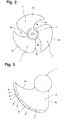
Fig. 2 is a rear view showing the hub and blades of the propeller fan illustrated inFig. 1 , as viewed from the side corresponding to the blade negative pressure surfaces; -
Fig. 3 is a rear view showing a blade of the propeller fan illustrated inFig. 1 , as viewed from the side corresponding to the blade negative pressure surfaces; -
Fig. 4 is a cross-sectional view taken along line a-a ofFig. 3 ; -
Fig. 5 is a perspective view showing a blade of the propeller fan illustrated inFig. 1 ; -
Fig. 6 is a partial cross-sectional view showing a blade of a propeller fan according to a second embodiment of the present invention; -
Fig. 7 is a partial cross-sectional view showing a blade of a propeller fan according to a third embodiment of the present invention; -
Fig. 8 is a partial cross-sectional view showing a blade of a propeller fan according to a fourth embodiment of the present invention; -
Fig. 9 is a rear view showing a blade of a propeller fan according to a fifth embodiment of the present invention, as viewed from the side corresponding to the blade negative pressure surfaces; -
Fig. 10 is a rear view showing a blade of a propeller fan according to a sixth embodiment of the present invention, as viewed from the side corresponding to the blade negative pressure surfaces; -
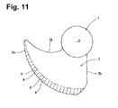
Fig. 11 is a rear view showing a blade of a propeller fan according to a seventh embodiment of the present invention, as viewed from the side corresponding to the blade negative pressure surfaces; -
Fig. 12 is a central longitudinal cross-sectional view showing a propeller fan according to an eighth embodiment of the present invention; -
Fig. 13 is a central longitudinal cross-sectional view showing a propeller fan according to a ninth embodiment of the present invention; -
Fig. 14 is a central longitudinal cross-sectional view showing a propeller fan according to a tenth embodiment of the present invention; and -
Fig. 15 is a perspective view showing a blade of a conventional propeller fan. -
Figs. 1 to 5 show a propeller fan according to a first embodiment of the present invention, which is an air blower of an outdoor unit of an air conditioner. - In
Figs. 1 and2 , thereference numeral 1 represents a cylindrical hub formed of synthetic resin including a rotational axis of the propeller fan. A plurality of (in the first embodiment, three)blades 2 are arranged on the outer circumferential surface of thehub 1 and formed integrally with thehub 1. - A blade portion formed by the
hub 1 and theblades 2 are arranged inside thebellmouth 4. Thebellmouth 4 includes a cylindrical airflow guide portion 4b and apartition plate portion 4a, which is arranged around theguide portion 4b. A gap S exists between the inner circumferential surface of theguide portion 4b of thebellmouth 4 and ablade tip 2c of each of theblades 2. - A leading
edge 2a of eachblade 2 is structured such that its distal portion (the outer portion) is located forward in the rotational direction of theblade 2 from its proximal portion (the inner portion). Similarly, atrailing edge 2b of eachblade 2 is structured such that its distal portion is located forward in the rotational direction of theblade 2 from its proximal portion. - As illustrated in
Figs. 3 to 5 , theblade tip 2c of eachblade 2 has a corrugated shape. More specifically, eachblade 2 has blade surfaces, which are a positive pressure surface and a negative pressure surface. In portions of these surfaces corresponding to theblade tip 2c, recessed portions A and projected portions B are formed alternately along the direction in which theblade tip 2c extends. The recessed portions A and the projected portions B, which alternate one another, are arranged continuously from the leadingedge 2a to thetrailing edge 2b. The depths of the recessed portions A, which are provided in both of the positive pressure surface and the negative pressure surface of eachblade 2, are equal. Similarly, the heights of the projected portions B, which are provided in both of the positive pressure surface and the negative pressure surface of eachblade 2, are equal. - The line extending along the deepest parts of each recessed portion A is parallel with a line connecting a point on the line along the deepest parts to the center of the
hub 1. The line extending along the highest parts of each projected portion B is parallel with a line connecting a point on the line along the highest parts to the center of thehub 1. The lines each extending along the deepest parts of a corresponding one of the recessed portions A, which recessed portions A are formed on both of the positive pressure surface and the negative pressure surfaces of eachblade 2, have the same length. Similarly, the lines each extending along the highest parts of a corresponding one of the projected portions B, which projected portions B are provided on both of the positive pressure surface and the negative pressure surface of eachblade 2, have the same length. In other words, the portion of eachblade 2 forming the corrugated shape has a constant width along the direction in which theblade tip 2c extends. - As illustrated in
Fig. 4 , the recessed portions A and the projected portions B of eachblade tip 2c are formed by deforming portions of theblade tip 2c that are spaced apart at predetermined intervals along the direction in which theblade tip 2c extends in such a manner that these portions project toward the negative pressure surface. - Since the
blade tip 2c of eachblade 2 has the corrugated shape as has been described, a leakage flow moving from the positive pressure surface to the negative pressure surface of theblade 2 via the gap S between thebellmouth 4 and theblade tip 2c forms minutely divided, intermittent, and small-scale vortexes as illustrated inFig. 5 . This prevents the leakage flow via the gap S from developing while moving from the leadingedge 2a to thetrailing edge 2b of eachblade 2 to form a large-scale blade tip vortex. The fan noise is thus reduced. Also, the load on actuation of a fan motor decreases, and the input of the fan motor is lowered. - The cross-sectional shape of each recessed portion A and the cross-sectional shape of each projected portion B may be angular or round. If the recessed portions A and the projected portions B have angular cross-sectional shapes, the minutely divided vortexes are produced efficiently. Contrastingly, if the recessed portions A and the projected portions B have round cross-sectional shapes, the minutely divided vortexes are produced smoothly.
- A second embodiment of the present invention is different from the first embodiment in that the recessed portions A and the projected portions B of each
blade tip 2c are formed by deforming portions of theblade tip 2c that are spaced apart at predetermined intervals in the direction in which theblade tip 2c extends in such a manner that these portions project toward the positive pressure surface of theblade 2 as illustrated inFig. 6 , instead of the negative pressure surface as illustrated inFig. 4 . - The second embodiment has the same advantages as the advantages of the above-described first embodiment.
- A third embodiment of the present invention is different from the first embodiment in that the recessed portions A and the projected portions B of each
blade tip 2c are formed by decreasing the thicknesses of portions of theblade tip 2c that are spaced apart at predetermined intervals in the direction in which theblade tip 2c extends compared to the other portions of theblade tip 2c, as illustrated inFig. 7 . More specifically, in the third embodiment, portions of the positive pressure surface corresponding to eachblade tip 2c that are spaced apart at the predetermined intervals in the extending direction of theblade tip 2c are recessed compared to the other portions of the positive pressure surface corresponding to theblade tip 2c. - In the third embodiment, the recessed portions A and the projected portions B are formed in a portion of the positive pressure surface of each
blade 2 corresponding to theblade tip 2c. In contrast, neither recessed portions A nor projected portions B are formed in a portion of the negative pressure surface of eachblade 2 corresponding to theblade tip 2c. However, even in this case, the same advantages as those of the first embodiment are obtained. Further, the third embodiment is advantageous in that the weight of eachblade 2 is easily reduced compared to the first and second embodiments. - A fourth embodiment of the present invention is different from the first embodiment in that the recessed portions A and the projected portions B of each
blade tip 2c are formed by increasing the thicknesses of portions of theblade tip 2c that are spaced apart at predetermined intervals in the direction in which theblade tip 2c extends compared to the other portions of theblade tip 2c, as illustrated inFig. 8 . More specifically, in the fourth embodiment, portions of the negative pressure surface corresponding to eachblade tip 2c that are spaced apart at the predetermined intervals in the extending direction of theblade tip 2c are projected compared to the other portions of the negative pressure surface corresponding to theblade tip 2c. - In the fourth embodiment, the recessed portions A and the projected portions B are formed in a portion of the negative pressure surface of each
blade 2 corresponding to theblade tip 2c. In contrast, neither recessed portions A nor the projected portions B are formed in a portion of the positive pressure surface of eachblade 2 corresponding to theblade tip 2c. However, even in this case, the same advantages as those of the first embodiment are obtained. - In a fifth embodiment of the present invention, the line extending along the deepest parts of each recessed portion A of each
blade tip 2c is not parallel with a line connecting a point on the line along the deepest parts to the center of thehub 1, but is inclined with respect to this line at a predetermined angle θ in the rotational direction of the blade 2 (toward theleading edge 2a), as illustrated inFig. 9 . Similarly, the line extending along the highest parts of each projected portion B of theblade tip 2c is not parallel with a line connecting a point on the line along the highest parts to the center of thehub 1, but is inclined with respect to this line at the same angle θ in the rotational direction of theblade 2. The fifth embodiment is different from the first embodiment in the above-described points. - In the fifth embodiment, the blade tip vortexes are efficiently broken by the recessed portions A and the projected portions B of each
blade tip 2c compared to the first embodiment. - In a sixth embodiment of the present invention, the line extending along the deepest parts of each recessed portion A of each
blade tip 2c is not parallel with a line connecting a point on the line along the deepest parts to the center of thehub 1, but is inclined with respect to this line at a predetermined angle θ in the direction opposite to the rotational direction of the blade 2 (toward the trailingedge 2b), as illustrated inFig. 10 . Similarly, the line extending along the highest parts of each projected portion B of theblade tip 2c is not parallel with a line connecting a point on the line along the highest parts to the center of thehub 1, but is inclined with respect to this line at the same angle θ in the direction opposite to the rotational direction of theblade 2. The sixth embodiment is different from the first embodiment in the above-described points. - In the sixth embodiment, as in the fifth embodiment, the blade tip vortexes are efficiently broken by the recessed portions A and the projected portions B of each
blade tip 2c compared to the first embodiment. - In a seventh embodiment of the present invention, the portion of each
blade 2 having the corrugated shape has a width increasing toward the trailingedge 2b, as illustrated inFig. 11 , instead of the constant width along the direction in which theblade tip 2c extends. The seventh embodiment is different from the first embodiment in this point. - In the seventh embodiment, the portion of each
blade 2 with the corrugated shape, which has the width increasing toward the trailingedge 2b, effectively suppresses generation of blade tip vortexes of scales enlarging toward the trailingedge 2b. - In eighth to tenth embodiments of the present invention, recessed portions A and projected portions B, which are alternately arranged in portions of the positive pressure surface and the negative pressure surface of each
blade 2 corresponding to theblade tip 2c, are not formed continuously from theleading edge 2a to the trailingedge 2b in both of the positive pressure surface and the negative pressure surface of theblade 2. In the eighth embodiment, the recessed portions A and the projected portions B are alternately formed only in the portion of eachblade tip 2c that corresponds to theguide portion 4b of thebellmouth 4, which is represented by the circle of the double-dotted line inFig. 12 . In the ninth embodiment, the recessed portions A and the projected portions B are alternately formed only in the portion of eachblade tip 2c that does not correspond to theguide portion 4b of thebellmouth 4, which is represented by the circle of the double-dotted line inFig. 13 . In the tenth embodiment, the recessed portions A and the projected portions B are alternately formed only in the boundary between the portion of eachblade tip 2c that corresponds to theguide portion 4b of thebellmouth 4 and the portion of theblade tip 2c that does not correspond to theguide portion 4b of thebellmouth 4, which boundary is represented by the circle of the double-dotted line inFig. 14 . - The eighth to tenth embodiments have the same advantages as the advantages of the first embodiment.
- Obviously, the present invention may be employed in any type of propeller fans serving as axial flow fans, regardless of blade shapes, including shapes of forward swept blades and rearward swept blades, or the number of the blades.
Claims (11)
- A propeller fan comprising:a hub;a plurality of blades extending from the hub; anda bellmouth inside which the hub and the blades are arranged,the propeller fan being characterized in that recessed portions and projected portions are alternately formed in a portion of a blade surface of each blade, which portion corresponds to a blade tip of the blade.
- The propeller fan according to claim 1, wherein the blade surface of each blade in which the recessed portions and the projected portions are formed is a blade positive pressure surface.
- The propeller fan according to claim 1, wherein the blade surface of each blade in which the recessed portions and the projected portions are formed is a blade negative pressure surface.
- The propeller fan according to claim 2 or 3, wherein the recessed portions and the projected portions are formed by providing portions with a great thickness and portions with a small thickness in the portion of each blade corresponding to the blade tip.
- The propeller fan according to claim 1, wherein the blade surface of each blade in which the recessed portions and the projected portions are formed is both of a blade positive pressure surface and a blade negative pressure surface.
- The propeller fan according to claim 5, wherein the recessed portions and the projected portions are formed by causing the portion of each blade corresponding to the blade tip to have a corrugated shape.
- The propeller fan according to any one of claims 1 to 6, wherein the recessed portions and the projected portions each have a round cross-sectional shape.
- The propeller fan according to any one of claims 1 to 6, wherein the recessed portions and the projected portions each have an angular cross-sectional shape.
- The propeller fan according to any one of claims 1 to 8, wherein the recessed portions and the projected portions are alternately formed along a direction in which the blade tip of each blade extends.
- The propeller fan according to any one of claims 1 to 9, wherein the portion of each blade in which the recessed portions and the projected portions are formed has a width increasing toward the trailing edge of the blade.
- The propeller fan according to any one of claims 1 to 10, wherein a line extending along the deepest parts of each recessed portion is inclined with respect to a line connecting a point on the line along the deepest parts to a center of the hub at a predetermined angle, and a line extending along the highest parts of each projected portion is inclined with respect to a line connecting a point on the line along the highest parts to the center of the hub at the same angle.
Applications Claiming Priority (2)
| Application Number | Priority Date | Filing Date | Title |
|---|---|---|---|
| JP2007181639 | 2007-07-11 | ||
| PCT/JP2008/062623 WO2009008513A1 (en) | 2007-07-11 | 2008-07-11 | Propeller fan |
Publications (2)
| Publication Number | Publication Date |
|---|---|
| EP2175141A1 true EP2175141A1 (en) | 2010-04-14 |
| EP2175141A4 EP2175141A4 (en) | 2016-08-31 |
Family
ID=40228683
Family Applications (1)
| Application Number | Title | Priority Date | Filing Date |
|---|---|---|---|
| EP08791104.6A Withdrawn EP2175141A4 (en) | 2007-07-11 | 2008-07-11 | HELICOID FAN |
Country Status (5)
| Country | Link |
|---|---|
| US (1) | US8512004B2 (en) |
| EP (1) | EP2175141A4 (en) |
| JP (1) | JP5125518B2 (en) |
| CN (1) | CN101688540A (en) |
| WO (1) | WO2009008513A1 (en) |
Families Citing this family (27)
| Publication number | Priority date | Publication date | Assignee | Title |
|---|---|---|---|---|
| JP4400686B2 (en) * | 2008-01-07 | 2010-01-20 | ダイキン工業株式会社 | Propeller fan |
| TWI443262B (en) * | 2010-12-29 | 2014-07-01 | Delta Electronics Inc | Fan and impeller thereof |
| CN102032215B (en) * | 2010-12-30 | 2012-07-04 | 北京理工大学 | Method for designing blade type with waveform surface |
| JP5203478B2 (en) | 2011-03-02 | 2013-06-05 | シャープ株式会社 | Cross-flow fan, molding die and fluid feeder |
| EP2530330B1 (en) * | 2011-06-01 | 2016-05-25 | MTU Aero Engines AG | Rotor blade for the compressor of a turbo engine, compressor and turbo machine |
| CN103032376B (en) * | 2011-10-09 | 2015-12-09 | 珠海格力电器股份有限公司 | Axial flow fan blade |
| CN102374194B (en) * | 2011-11-10 | 2017-05-10 | 美的集团股份有限公司 | Axial flow wind wheel |
| JP2013249787A (en) * | 2012-06-01 | 2013-12-12 | Daikin Industries Ltd | Propeller fan |
| EP2711558B1 (en) * | 2012-09-24 | 2020-07-08 | Samsung Electronics Co., Ltd. | Propeller fan |
| CN103899575A (en) * | 2012-12-26 | 2014-07-02 | 珠海格力电器股份有限公司 | Axial flow fan blade and air conditioner with same |
| AU353966S (en) * | 2013-08-05 | 2014-02-26 | Mitsubishi Electric Corp | Propeller fan |
| AU353962S (en) * | 2013-08-05 | 2014-02-26 | Mitsubishi Electric Corp | Propeller fan |
| CN104832456B (en) * | 2014-02-10 | 2017-02-22 | 珠海格力电器股份有限公司 | Fan |
| JP6588833B2 (en) * | 2016-01-18 | 2019-10-09 | 東芝キヤリア株式会社 | Propeller fan and heat source unit |
| USD901669S1 (en) | 2017-09-29 | 2020-11-10 | Carrier Corporation | Contoured fan blade |
| CN110118194B (en) * | 2018-02-07 | 2024-05-28 | 广东美的制冷设备有限公司 | Axial flow fan and air conditioner |
| EP3882470B1 (en) * | 2018-11-22 | 2025-12-17 | GD Midea Air-Conditioning Equipment Co., Ltd. | Axial-flow impeller and air-conditioner having the same |
| US20200224669A1 (en) * | 2019-01-11 | 2020-07-16 | Dyna Rechi Co., Ltd. | Fan blade structure |
| USD980965S1 (en) | 2019-05-07 | 2023-03-14 | Carrier Corporation | Leading edge of a fan blade |
| US11187083B2 (en) | 2019-05-07 | 2021-11-30 | Carrier Corporation | HVAC fan |
| KR102495315B1 (en) * | 2022-01-27 | 2023-02-06 | 김윤성 | An axial flow impeller having a self-balancing function by a balancing groove and an axial flow pump having the same |
| CN114856712B (en) * | 2022-05-19 | 2024-09-10 | 中国航空发动机研究院 | Blade with bionic blade top and open rotor with blade |
| KR20240051599A (en) | 2022-10-13 | 2024-04-22 | 엘지전자 주식회사 | Fan and air conditioning apparatus using the same |
| KR20240051598A (en) | 2022-10-13 | 2024-04-22 | 엘지전자 주식회사 | Fan and air conditioning apparatus using the same |
| CN116006510A (en) * | 2023-01-10 | 2023-04-25 | 西安泛仕达流体机械有限公司 | Axial flow fan blade |
| US12601361B2 (en) * | 2024-01-19 | 2026-04-14 | Asia Vital Components Co., Ltd. | Fan impeller structure |
| FR3160216A1 (en) * | 2024-03-18 | 2025-09-19 | Valeo Systemes Thermiques | Fan propeller |
Family Cites Families (13)
| Publication number | Priority date | Publication date | Assignee | Title |
|---|---|---|---|---|
| US2899128A (en) * | 1959-08-11 | Vaghi | ||
| JPS557982A (en) * | 1978-06-26 | 1980-01-21 | Wallace Murray Corp | Cooling fan |
| US4274806A (en) * | 1979-06-18 | 1981-06-23 | General Electric Company | Staircase blade tip |
| JPH0544695A (en) | 1991-08-08 | 1993-02-23 | Matsushita Refrig Co Ltd | Blower |
| JP2924372B2 (en) * | 1991-11-26 | 1999-07-26 | 松下電器産業株式会社 | Axial fan motor fan |
| JP2789188B2 (en) * | 1996-12-02 | 1998-08-20 | 西芝電機株式会社 | Axial blower |
| JP2001280293A (en) * | 2000-03-30 | 2001-10-10 | Sanyo Electric Co Ltd | Wind sending device |
| US6899525B2 (en) * | 2002-07-22 | 2005-05-31 | Arthur Vanmoor | Blade and wing configuration |
| US7136285B1 (en) * | 2003-08-04 | 2006-11-14 | Edward Herbert | Wave-fans and wave-fans with heat sinks |
| DE502004009528D1 (en) * | 2004-06-02 | 2009-07-09 | Rolls Royce Deutschland | Compressor blade with reduced aerodynamic blade excitation |
| JP2006200457A (en) * | 2005-01-21 | 2006-08-03 | Matsushita Electric Ind Co Ltd | Blower |
| US8083487B2 (en) * | 2007-07-09 | 2011-12-27 | General Electric Company | Rotary airfoils and method for fabricating same |
| EP2438299A2 (en) * | 2009-06-03 | 2012-04-11 | Flodesign Wind Turbine Corporation | Wind turbine blades with mixer lobes |
-
2008
- 2008-01-07 JP JP2008000519A patent/JP5125518B2/en not_active Expired - Fee Related
- 2008-07-11 US US12/668,158 patent/US8512004B2/en not_active Expired - Fee Related
- 2008-07-11 CN CN200880023070A patent/CN101688540A/en active Pending
- 2008-07-11 EP EP08791104.6A patent/EP2175141A4/en not_active Withdrawn
- 2008-07-11 WO PCT/JP2008/062623 patent/WO2009008513A1/en not_active Ceased
Non-Patent Citations (1)
| Title |
|---|
| See references of WO2009008513A1 * |
Also Published As
| Publication number | Publication date |
|---|---|
| JP5125518B2 (en) | 2013-01-23 |
| EP2175141A4 (en) | 2016-08-31 |
| US8512004B2 (en) | 2013-08-20 |
| WO2009008513A1 (en) | 2009-01-15 |
| JP2009036187A (en) | 2009-02-19 |
| US20100322779A1 (en) | 2010-12-23 |
| CN101688540A (en) | 2010-03-31 |
Similar Documents
| Publication | Publication Date | Title |
|---|---|---|
| US8512004B2 (en) | Propeller fan | |
| KR102317338B1 (en) | Blower and outdoor unit of air conditioner having the same | |
| EP2902639B1 (en) | Propeller fan and air conditioner equipped with same | |
| US8721280B2 (en) | Propeller fan | |
| EP2570677B1 (en) | Axial flow blower | |
| US8011891B2 (en) | Centrifugal multiblade fan | |
| JP5425192B2 (en) | Propeller fan | |
| JP6914371B2 (en) | Axial blower | |
| US20110014052A1 (en) | Fan with structural support ring | |
| US8197217B2 (en) | Axial flow fan | |
| EP1953391A1 (en) | Multi-vane centrifugal blower | |
| EP4212737A1 (en) | Propeller fan | |
| JP2019127865A (en) | Centrifugal fan | |
| JP7069406B2 (en) | Propeller fan and blower | |
| JP2020094549A (en) | Propeller fan | |
| CN104214137A (en) | Propeller type fan |
Legal Events
| Date | Code | Title | Description |
|---|---|---|---|
| PUAI | Public reference made under article 153(3) epc to a published international application that has entered the european phase |
Free format text: ORIGINAL CODE: 0009012 |
|
| 17P | Request for examination filed |
Effective date: 20100108 |
|
| AK | Designated contracting states |
Kind code of ref document: A1 Designated state(s): AT BE BG CH CY CZ DE DK EE ES FI FR GB GR HR HU IE IS IT LI LT LU LV MC MT NL NO PL PT RO SE SI SK TR |
|
| AX | Request for extension of the european patent |
Extension state: AL BA MK RS |
|
| DAX | Request for extension of the european patent (deleted) | ||
| RA4 | Supplementary search report drawn up and despatched (corrected) |
Effective date: 20160803 |
|
| RIC1 | Information provided on ipc code assigned before grant |
Ipc: F04D 29/66 20060101ALI20160728BHEP Ipc: F04D 29/38 20060101AFI20160728BHEP |
|
| STAA | Information on the status of an ep patent application or granted ep patent |
Free format text: STATUS: REQUEST FOR EXAMINATION WAS MADE |
|
| STAA | Information on the status of an ep patent application or granted ep patent |
Free format text: STATUS: THE APPLICATION IS DEEMED TO BE WITHDRAWN |
|
| 18D | Application deemed to be withdrawn |
Effective date: 20170302 |