EP2175120A2 - Method and system for operating a turbomachine having an unchoked valve - Google Patents
Method and system for operating a turbomachine having an unchoked valve Download PDFInfo
- Publication number
- EP2175120A2 EP2175120A2 EP09172064A EP09172064A EP2175120A2 EP 2175120 A2 EP2175120 A2 EP 2175120A2 EP 09172064 A EP09172064 A EP 09172064A EP 09172064 A EP09172064 A EP 09172064A EP 2175120 A2 EP2175120 A2 EP 2175120A2
- Authority
- EP
- European Patent Office
- Prior art keywords
- syngas
- fuel supply
- supply system
- turbomachine
- valve
- Prior art date
- Legal status (The legal status is an assumption and is not a legal conclusion. Google has not performed a legal analysis and makes no representation as to the accuracy of the status listed.)
- Granted
Links
- 238000000034 method Methods 0.000 title claims abstract description 75
- 239000000446 fuel Substances 0.000 claims abstract description 144
- 238000002485 combustion reaction Methods 0.000 claims description 41
- 238000011144 upstream manufacturing Methods 0.000 claims description 10
- 230000006870 function Effects 0.000 description 12
- VNWKTOKETHGBQD-UHFFFAOYSA-N methane Chemical compound C VNWKTOKETHGBQD-UHFFFAOYSA-N 0.000 description 12
- 238000004590 computer program Methods 0.000 description 10
- 238000010586 diagram Methods 0.000 description 10
- 238000012545 processing Methods 0.000 description 8
- 239000007789 gas Substances 0.000 description 6
- 239000012530 fluid Substances 0.000 description 5
- 239000003345 natural gas Substances 0.000 description 5
- 238000007792 addition Methods 0.000 description 3
- 230000003287 optical effect Effects 0.000 description 3
- 238000003860 storage Methods 0.000 description 3
- 230000008901 benefit Effects 0.000 description 2
- 238000012986 modification Methods 0.000 description 2
- 230000004048 modification Effects 0.000 description 2
- 230000008569 process Effects 0.000 description 2
- 238000012546 transfer Methods 0.000 description 2
- 230000007704 transition Effects 0.000 description 2
- 230000009286 beneficial effect Effects 0.000 description 1
- 230000005540 biological transmission Effects 0.000 description 1
- 230000008859 change Effects 0.000 description 1
- 238000009792 diffusion process Methods 0.000 description 1
- 230000000694 effects Effects 0.000 description 1
- 230000005611 electricity Effects 0.000 description 1
- 238000012423 maintenance Methods 0.000 description 1
- 238000004519 manufacturing process Methods 0.000 description 1
- 102000027424 natriuretic peptide receptors Human genes 0.000 description 1
- 108091008599 natriuretic peptide receptors Proteins 0.000 description 1
- 239000013307 optical fiber Substances 0.000 description 1
- 238000011084 recovery Methods 0.000 description 1
- 239000004065 semiconductor Substances 0.000 description 1
- 238000009987 spinning Methods 0.000 description 1
Images


Classifications
-
- F—MECHANICAL ENGINEERING; LIGHTING; HEATING; WEAPONS; BLASTING
- F02—COMBUSTION ENGINES; HOT-GAS OR COMBUSTION-PRODUCT ENGINE PLANTS
- F02C—GAS-TURBINE PLANTS; AIR INTAKES FOR JET-PROPULSION PLANTS; CONTROLLING FUEL SUPPLY IN AIR-BREATHING JET-PROPULSION PLANTS
- F02C9/00—Controlling gas-turbine plants; Controlling fuel supply in air- breathing jet-propulsion plants
- F02C9/26—Control of fuel supply
- F02C9/40—Control of fuel supply specially adapted to the use of a special fuel or a plurality of fuels
-
- F—MECHANICAL ENGINEERING; LIGHTING; HEATING; WEAPONS; BLASTING
- F01—MACHINES OR ENGINES IN GENERAL; ENGINE PLANTS IN GENERAL; STEAM ENGINES
- F01K—STEAM ENGINE PLANTS; STEAM ACCUMULATORS; ENGINE PLANTS NOT OTHERWISE PROVIDED FOR; ENGINES USING SPECIAL WORKING FLUIDS OR CYCLES
- F01K23/00—Plants characterised by more than one engine delivering power external to the plant, the engines being driven by different fluids
- F01K23/02—Plants characterised by more than one engine delivering power external to the plant, the engines being driven by different fluids the engine cycles being thermally coupled
- F01K23/06—Plants characterised by more than one engine delivering power external to the plant, the engines being driven by different fluids the engine cycles being thermally coupled combustion heat from one cycle heating the fluid in another cycle
- F01K23/10—Plants characterised by more than one engine delivering power external to the plant, the engines being driven by different fluids the engine cycles being thermally coupled combustion heat from one cycle heating the fluid in another cycle with exhaust fluid of one cycle heating the fluid in another cycle
-
- F—MECHANICAL ENGINEERING; LIGHTING; HEATING; WEAPONS; BLASTING
- F02—COMBUSTION ENGINES; HOT-GAS OR COMBUSTION-PRODUCT ENGINE PLANTS
- F02C—GAS-TURBINE PLANTS; AIR INTAKES FOR JET-PROPULSION PLANTS; CONTROLLING FUEL SUPPLY IN AIR-BREATHING JET-PROPULSION PLANTS
- F02C3/00—Gas-turbine plants characterised by the use of combustion products as the working fluid
- F02C3/20—Gas-turbine plants characterised by the use of combustion products as the working fluid using a special fuel, oxidant, or dilution fluid to generate the combustion products
- F02C3/22—Gas-turbine plants characterised by the use of combustion products as the working fluid using a special fuel, oxidant, or dilution fluid to generate the combustion products the fuel or oxidant being gaseous at standard temperature and pressure
-
- F—MECHANICAL ENGINEERING; LIGHTING; HEATING; WEAPONS; BLASTING
- F02—COMBUSTION ENGINES; HOT-GAS OR COMBUSTION-PRODUCT ENGINE PLANTS
- F02C—GAS-TURBINE PLANTS; AIR INTAKES FOR JET-PROPULSION PLANTS; CONTROLLING FUEL SUPPLY IN AIR-BREATHING JET-PROPULSION PLANTS
- F02C7/00—Features, components parts, details or accessories, not provided for in, or of interest apart form groups F02C1/00 - F02C6/00; Air intakes for jet-propulsion plants
- F02C7/22—Fuel supply systems
Definitions
- the present application relates generally to a fuel supply system on a turbomachine; and more particularly to, a method of operating a turbomachine having a fuel supply system with at least one unchoked valve.
- Some turbomachines such as, but not limiting of, a gas turbine, an aero-derivative turbine, or the like, have multiple fuel supply systems. These fuel supply systems generally feed into at least one combustion can of a combustion system.
- a primary fuel supply system may use a natural gas as the fuel source; and a secondary fuel supply system may use a synthetic gas (hereinafter "syngas”) as the fuel source.
- syngas synthetic gas
- Each fuel supply system may operate as the sole fuel source to the combustion system. Alternatively, these fuel supply systems may simultaneously supply fuel to the turbomachine.
- Turbomachines generally include a compressor, a combustion system having a plurality of combustion cans, a fuel supply system, and a turbine section.
- the fuel supply system delivers a fuel, such as, but not limiting of, methane to the combustion system.
- Some turbomachines include a Dry-Low Nox (DLN) controls system; which may require the use of a "choked" valve for providing a choked flow.
- DNN Dry-Low Nox
- choking flow occurs when a fluid flows at a sonic velocity.
- the pressure upstream of the valve should be increased in order to increase the flow downstream of the valve.
- the differential pressure (DP) across the valve typically creates the sonic flow.
- Choked flow may provide system stability by not reacting to pressure fluctuations downstream of the valve, which may be the result of changing conditions in the turbomachine. Choked flow is typically beneficial to turbomachine operation because downstream pressure fluctuations may not create a flow disturbance in the fuel supply system.
- a choked valve in a fuel supply system typically costs more than an unchoked valve.
- the pressure drop across a choked valve is higher than an unchoked valve. This generally requires that a gas compressor, or the like, perform more work to meet the necessary pressure requirement.
- Non-DLN types of combustion systems generally do not require a choked valve.
- combustion systems using a syngas typically do not require choked flow. These systems may burn the syngas using a diffusion form of combustion.
- the pressure range upstream of an unchoked valve may be of a broader range than that of a choked valve.
- an upstream gas compressor performs less work to maintain the pressure upstream of the unchoked valve.
- these systems may require a flow meter to control the fuel flow to the syngas fuel supply system. The flow meter adds cost and may introduce reliability concerns to the non-DLN combustion system.
- the method should not require a flow meter to control a fuel supply system comprising at least one unchoked valve.
- a method of operating a turbomachine comprising a plurality of combustion cans capable of burning a syngas, wherein the turbomachine comprises at least one unchoked valve, the method comprising: providing a syngas fuel supply system wherein the non-syngas fuel supply system is integrated with the turbomachine and the syngas fuel supply system comprises an unchoked valve; providing a non-syngas fuel supply system wherein the syngas fuel supply system is integrated with the turbomachine; determining whether to operate the turbomachine under a syngas operation, wherein the syngas operation utilizes the syngas fuel supply system; and determining whether the syngas operation is a solo mode or a co-fire mode; wherein the solo mode comprises utilizing the plurality of combustions cans to burn a syngas received from the syngas fuel supply system; and wherein the co-fire mode comprises utilizing the plurality of combustions cans to burn a syngas received from the syngas fuel supply system and to burn a non-syngas
- a system for controlling an operating a turbomachine comprising: a turbomachine comprising a plurality of combustion cans; a syngas fuel supply system integrated with the combustion system, wherein the syngas fuel supply system comprises at least one unchoked valve; a turbine control system comprising a syngas controller and a non-syngas controller; wherein the turbine control system: controls an operation of the syngas fuel supply system; operates the syngas operation under a solo mode or a co-fire mode; wherein the solo mode comprises operating the turbomachine utilizing the syngas fuel supply system; and wherein the co-fire mode comprises operating the turbomachine utilizing the syngas fuel supply system and the non-syngas fuel supply system.
- An embodiment of the present invention may provide a fuel supply system with a configuration comprising at least one unchoked valve. Furthermore, this embodiment of the present invention may comprise a fuel supply system that does not include a flow meter.
- An embodiment of the present invention provides a method of controlling a turbomachine having at least one fuel supply system that uses an unchoked valve.
- the method may determine the flow characteristics of a fuel in a fuel supply system without using a flow meter.
- the method of an embodiment of the present invention may simultaneous control a turbomachine having multiple fuel supply systems; which may include a primary fuel supply system and a secondary fuel supply system.
- the primary fuel supply system may have the form of a non-syngas fuel supply system, which may use a natural gas as the fuel source.
- the secondary fuel supply system may have the form of a syngas fuel supply system, which may use a syngas as the fuel source.
- the method of an embodiment of the present invention may determine whether to operate the turbomachine in a single mode or in a co-fire mode.
- the single mode may be considered a mode where only the syngas fuel supply system supplies fuel to the combustion system of the turbomachine.
- the co-fire mode may be considered a mode where both the syngas fuel supply system and the non-syngas fuel supply system supply fuel to the combustion system of the turbomachine.
- a turbomachine 100 includes: a compressor section 110; a plurality of combustion cans 120 of a combustion system, with each can 120 comprising a plurality of fuel nozzles 125; a turbine section 130; and a flow path 135 leading to a transition section 140.
- a syngas fuel supply system 150 may provide a syngas to the combustion system.
- a non-syngas fuel supply system 160 may provide a fuel, such as, but not limiting of, a natural gas, to the combustion system.
- the compressor section 110 includes a plurality of rotating blades (not illustrated) and stationary vanes (not illustrated) structured to compress a fluid.
- the plurality of combustion cans 120 may be coupled to the syngas fuel supply system 150 and the non-syngas fuel supply system 160. Within each combustion can 120 the compressed air and fuel are mixed, ignited, and consumed within the flow path 135, thereby creating a working fluid.
- the flow path 135 of the working fluid generally proceeds from the aft end of the plurality of fuel nozzles 125 downstream through the transition section 140 into the turbine section 130.
- the turbine section 130 includes a plurality of rotating and stationary components, neither of which are shown, and converts the working fluid to a mechanical torque, which may be used to generate electricity via the generator 170.
- the output of the generator 170 may be used by a turbine control system 190, or the like, as a parameter to control the operation of the turbomachine 100.
- Exhaust of the turbomachine 100 may be captured via a heat recovery steam generator (not illustrated), or the like.
- Exhaust temperature data 180 may be used by a turbine control system 190, or the like, as a parameter to control the operation of the turbomachine 100.
- FIG. 2 is a schematic illustrating a syngas and a non-syngas fuel supply systems 150, 160, in accordance with an embodiment of the present invention.
- An embodiment of the turbomachine 100 may comprise combustion cans 120 that may receive fuel from the syngas and the non-syngas fuel supply systems 150, 160.
- An embodiment of the syngas fuel supply system 150 may deliver a syngas to the combustion cans 120.
- An embodiment of the non-syngas fuel supply system 160 may deliver a natural gas or other non-syngas fuel to the combustion cans 120.
- An embodiment of the syngas fuel supply system 150 may comprise: a syngas processing unit 200 for delivering a syngas; a first syngas valve 205, which may function as a stop valve; a second syngas valve 210, which may function as a control valve; a syngas manifold 215, which may transfer the syngas to the plurality of combustion cans 120; and a syngas controller 220, which may control the operation of the syngas fuel supply system 150.
- the syngas controller 220 may be integrated with the turbine control system 190.
- the second syngas valve 210 may have the form of an unchoked valve.
- An embodiment of the non-syngas fuel supply system 160 may comprise: a first non-syngas valve 225, which may function as a stop valve; a second non-syngas valve 230, which may function as a control valve; a non-syngas manifold 235, which may transfer the fuel to the plurality of combustion cans 120; and a non-syngas controller 240, which may control the operation of the non-syngas fuel supply system 160.
- the non-syngas controller 240 may be integrated with the turbine control system 190.
- Figure 2 also illustrates a crossover valve 245, which may be in a line that links that syngas fuel supply system 150 with the non-syngas fuel supply system 160.
- the crossover valve 245 may allow syngas from the syngas fuel supply system 150 to enter the non-syngas fuel supply system 160. This may allow the non-syngas manifold 235 to achieve and/or maintain a desired range of manifold pressures, while the turbomachine 100 is operating in a co-fire mode.
- the present invention may be embodied as a method, system, or computer program product. Accordingly, the present invention may take the form of an entirely hardware embodiment, an entirely software embodiment (including firmware, resident software, micro-code, etc.) or an embodiment combining software and hardware aspects all generally referred to herein as a "circuit", "module,” or " system”. Furthermore, the present invention may take the form of a computer program product on a computer-usable storage medium having computer-usable program code embodied in the medium.
- the computer-usable or computer-readable medium may be, for example but not limited to, an electronic, magnetic, optical, electromagnetic, infrared, or semiconductor system, apparatus, device, or propagation medium. More specific examples (a non- exhaustive list) of the computer-readable medium would include the following: an electrical connection having one or more wires, a portable computer diskette, a hard disk, a random access memory (RAM), a read-only memory (ROM), an erasable programmable read-only memory (EPROM or Flash memory), an optical fiber, a portable compact disc read-only memory (CD-ROM), an optical storage device, a transmission media such as those supporting the Internet or an intranet, or a magnetic storage device.
- the computer-usable or computer-readable medium could even be paper or another suitable medium upon which the program is printed, as the program can be electronically captured, via, for instance, optical scanning of the paper or other medium, then compiled, interpreted, or otherwise processed in a suitable manner, if necessary, and then stored in a computer memory.
- a computer-usable or computer-readable medium may be any medium that can contain, store, communicate, propagate, or transport the program for use by or in connection with the instruction execution system, apparatus, or device.
- Computer program code for carrying out operations of the present invention may be written in an object oriented programming language such as Java7, Smalltalk or C++, or the like, including different versions of the aforementioned languages.
- the computer program code for carrying out operations of the present invention may also be written in conventional procedural programming languages, such as the "C" programming language, or a similar language.
- the program code may execute entirely on the user's computer, partly on the user's computer, as a stand-alone software package, partly on the user's computer and partly on a remote computer or entirely on the remote computer.
- the remote computer may be connected to the user's computer through a local area network (LAN), a wide area network (WAN) a wireless network and combinations thereof; or the connection may be made to an external computer (for example, through the Internet using an Internet Service Provider).
- LAN local area network
- WAN wide area network
- Internet Service Provider an Internet Service Provider
- These computer program instructions may also be stored in a computer-readable memory that can direct a computer or other programmable data processing apparatus to function in a particular manner, such that the instructions stored in the computer-readable memory produce an article of manufacture including instruction means which implement the function/act specified in the flowchart and/or block diagram block or blocks.
- the computer program instructions may also be loaded onto a computer or other programmable data processing apparatus to cause a series of operational steps to be performed on the computer or other programmable apparatus to produce a computer implemented process such that the instructions which execute on the computer or other programmable apparatus provide steps for implementing the functions/acts specified in the flowchart and/or block diagram block or blocks.
- An embodiment of the present invention takes the form of an application and process that has the technical effect of controlling the operating of a turbomachine 100 with a primary fuel supply system 150 and a secondary fuel supply system 160.
- the present invention may determine whether combustion cans 120 receive fuel from the primary fuel supply system 150; the secondary fuel supply system 160; or a combination of the primary and secondary fuel supply systems 150, 160.
- FIGS. 3A-3C are flowcharts illustrating a method 300 of operating a turbomachine 100, in accordance with an embodiment of the present invention.
- the method 300 may include at least one turbine control system, which may function, for example, but not limiting of, in steps 305 to 380.
- the method 300 may be integrated with a graphical user interface (GUI), or the like.
- GUI graphical user interface
- the GUI may allow the operator to navigate through the method 300 described below.
- the GUI may also provide at least one notification of the status of the method 300.
- the turbomachine 100 may be operating in a mode allowing for a syngas operation.
- the turbomachine 100 may be operating solely on the primary fuel supply system 150.
- the combustion system of the turbomachine 100 may be burning a natural gas, while operating at spinning reserve.
- the method 300 may determine whether to begin a syngas operation.
- the GUI may provide a notification to an operator asking whether a syngas operation should commence.
- the method 300 may determine whether an operational permissive(s) required for syngas operation is satisfied before providing the notification to the operation. If a syngas operation is to start, then the method 300 may proceed to step 315; otherwise the method 300 may revert to step 305.
- the method 300 may determine an operational mode of the syngas fuel supply system.
- the method 300 may control multiple fuel supply systems.
- the operator may select from operating the turbomachine 100 in a syngas only mode.
- the syngas fuel supply system 150 may provide the sole fuel entering the plurality of combustion cans 120.
- the operator may select a co-fire mode where the syngas fuel supply system 150 and the non-syngas fuel supply system 160 may supply the fuel to the plurality of combustion cans 120. If a syngas only mode is selected, then the method 300 may proceed to step 320, illustrated in Figure 3B ; otherwise the method 300 may proceed to step 350, illustrated in Figure 3C .
- an embodiment of the present invention may provide a syngas fuel supply system 150 having at least one unchoked valve.
- the second syngas gas valve 210 may be an unchoked control valve.
- the method 300 may not require a flow meter to determine the flow through an unchoked valve. This feature may benefit an operator of the turbomachine 100 by reducing the overall cost and maintenance, while improving plant efficiency and reliability of the syngas fuel supply system 150.
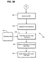
- FIG. 3B illustrates steps 320-345, which may control the turbomachine 100 under a syngas only mode.
- the method 300 may control determine a Fuel Stroke Reference (FSR) of a syngas only operation.
- the FSR may be considered the "called-for-fuel”.
- FSR may represent the amount of fuel required to be combusted to satisfy a desired turbomachine output; such as, but not limiting of, a generator output, an exhaust temperature setpoint, or the like.
- the FSR value may derive from an FSR selection algorithm (not illustrated). This algorithm may select a FSR value from a plurality of FRS values.
- FSR_A may correspond to a called-for-fuel value for a generator output
- FSR_B may correspond to a called-for-fuel value for a specific exhaust temperature setpoint..
- the method 300 may determine a flow reference for at least one unchoked control valve.
- An embodiment of the method 300 may modify the FSR value from step 320 to determine the flow reference.
- the method 300 may use a scaling method to scale the FSR value to create the flow reference.
- the method 300 may determine a range for a required Critical Flow Capacity (Cg) value of the at least one unchoked valve.
- the method 300 may incorporate an algorithm to determine a range for a required Cg of the unchoked valve.
- the algorithm may receive operation data, illustrated in step 335, to calculate the Cg value.
- the operation data may include, for example, but not limiting of, a molecular weight of the syngas used in the syngas fuel supply system 150; the pressure and the temperature of the syngas upstream of the unchoked valve; and a differential pressure of an unchoked valve, such as, but not limiting of, the syngas valve 210.
- the algorithm may also determine a nozzle pressure ratio (NPR) of the syngas manifold 215.
- the NPR may assist with maintaining acceptable combustion dynamics within the combustion cans 120.
- the algorithm may include a maximum NPR value and a minimum NPR value.
- the GUI of the method 300 notify the operator if the NPR determined by the algorithms is outside of the range between the minimum and maximum NPR values.
- the minimum and maximum NPR values may set by the operator.
- default values the minimum and maximum NPR values may be preconfigured within the algorithm.
- the method 300 may determine a required position of the at least one unchoked valve. For example, but not limiting of, the method 300 may determine the required position of the second syngas valve 210 in order to satisfy the FSR target. Alternatively, the method 300 may determine the required position of a plurality of valves in order to satisfy the FSR target.
- the method 300 may adjust the position of at least one unchoked valve, such as, but not limiting of, the second syngas valve 210.
- the method 300 may stroke each valve to the position determined in step 340.
- the method 300 may continually determine the FSR value based on the received operating parameters, repeating steps 320-345.
- Figure 3C illustrates steps 350-380, which may control the turbomachine 100 under a co-fire mode, where a syngas and a non-syngas may be simultaneously burned within the plurality of combustion cans 120.
- the method 300 may include an operational order, which prioritizes syngas operation over non-syngas operation.
- the priority of the turbomachine operation may be as follows: 1) ensure that the syngas generated by syngas processing unit 200 is consumed by the turbomachine 100; 2) ensure that the NPRs of the syngas fuel supply system 150, and the non-syngas fuel supply system 160 are maintained within desired limits; and 4) the desired turbomachine 100 operating output is satisfied.
- the method 300 may receive at least one operating target.
- An operating target may be considered a desired output from the turbomachine 100.
- an operating target may include: an output of the generator, an exhaust temperature setpoint, or the like.
- the operating target may be the selection of maintaining a syngas fuel supply system pressure and/or achieving an operating output exceeding the capacity of the syngas fuel supply system in order to achieve maximum syngas consumption.
- the method 300 may determine a fuel source ratio; which may be considered the split among the total fuel consumed by the turbomachine 100, between the syngas and the non-syngas.
- a fuel source ratio of 90/10 may represent that the total fuel consumed by the turbomachine is 90% syngas and 10% non-syngas.
- the method 300 may simultaneously control the syngas operation in steps 360 and 365; and the non-syngas operation in steps 370 and 375.
- the method 300 may receive a target manifold pressure for the syngas fuel supply system 150.
- the target manifold pressure may be determined, in part, by the output of the syngas processing unit 200.
- the method 300 may prioritize the consumption of the generated syngas by the turbomachine 100.
- the method 300 may comprises an algorithm that receives data from the output of the syngas processing unit 200. The algorithm may then determine an appropriate range of the pressure of the syngas gas manifold 215.
- the method 300 may determine a required position of at least one valve in the syngas fuel supply system 150 that may maintain the manifold pressure determined in step 360. For example, but not limiting of, the method 300 may determine the position of the syngas control valve 210 that may allow sufficient flow for maintaining a desired pressure of the syngas manifold 215. The position of valve 210 may be continuously adjusted until a pressure target for the syngas fuel supply system 150 is satisfied.
- the method 300 may receive a target FSR for the non-syngas fuel supply system 160.
- the target FSR may be considered the FSR value required to meet the desired operational targets. For example, but not limiting of, if the operational target is a generator output of 100 megawatts.
- the syngas fuel supply system 150 may generate 75 megawatts.
- the target FSR value for the non-syngas fuel supply system 160 may be a value that can generate 25 megawatts allowing the turbomachine to meet the operational target of 100 megawatts.
- the method 300 may determine a required position of at least one valve in the non-syngas fuel supply system 160 that may meet the FSR target generated in step 370. For example, but not limiting of, the method 300 may determine the position of the non-syngas control valve 230 that may allow sufficient flow to meet the aforementioned operational target(s). Here, the method 300 may continuously adjust the valve 215 until the target is achieved and/or maintained.
- the method 300 may determine whether the operational target(s) is within a desired range. For example, but not limiting of, the method 300 may be compared a target generator output with the actual generator output. Here, the method 300 may continuously executes steps 350-380 to achieve and/or maintain a target output. Furthermore, if the operational target changes, the FSR value may also change. Here, if the desired generator output is increased to 125 megawatts from 100 megawatts, then the target FSR value for the non-syngas fuel supply system 160 may be increased to a value that can generate 50 megawatts allowing the turbomachine to meet the operational target of 125 megawatts.
- the method 300 may attempt to ensure that the nozzle pressure ratio (NPR) of the non-syngas fuel supply system 160 is within a range, as previously described. If the NPR is outside of the range, then the method 300 may adjust the stroke of the crossover valve 245 provided that the operational targets may be maintained.
- NPR nozzle pressure ratio
- each step in the flowchart or step diagrams may represent a module, segment, or portion of code, which comprises one or more executable instructions for implementing the specified logical function(s).
- the functions noted in the step may occur out of the order noted in the figures. For example, two steps shown in succession may, in fact, be executed substantially concurrently, or the steps may sometimes be executed in the reverse order, depending upon the functionality involved.
- each step of the step diagrams and/or flowchart illustration, and combinations of steps in the step diagrams and/or flowchart illustration can be implemented by special purpose hardware-based systems which perform the specified functions or acts, or combinations of special purpose hardware and computer instructions.
Abstract
Description
- The present application relates generally to a fuel supply system on a turbomachine; and more particularly to, a method of operating a turbomachine having a fuel supply system with at least one unchoked valve.
- Some turbomachines, such as, but not limiting of, a gas turbine, an aero-derivative turbine, or the like, have multiple fuel supply systems. These fuel supply systems generally feed into at least one combustion can of a combustion system. A primary fuel supply system may use a natural gas as the fuel source; and a secondary fuel supply system may use a synthetic gas (hereinafter "syngas") as the fuel source. Each fuel supply system may operate as the sole fuel source to the combustion system. Alternatively, these fuel supply systems may simultaneously supply fuel to the turbomachine.
- Turbomachines generally include a compressor, a combustion system having a plurality of combustion cans, a fuel supply system, and a turbine section. Typically, the fuel supply system delivers a fuel, such as, but not limiting of, methane to the combustion system. Some turbomachines include a Dry-Low Nox (DLN) controls system; which may require the use of a "choked" valve for providing a choked flow.
- Generally, "choking flow" occurs when a fluid flows at a sonic velocity. When the sonic velocity is reached the pressure upstream of the valve should be increased in order to increase the flow downstream of the valve. The differential pressure (DP) across the valve typically creates the sonic flow.
- Choked flow may provide system stability by not reacting to pressure fluctuations downstream of the valve, which may be the result of changing conditions in the turbomachine. Choked flow is typically beneficial to turbomachine operation because downstream pressure fluctuations may not create a flow disturbance in the fuel supply system.
- For a few reasons, the costs associated with incorporating a choked valve into a fuel supply system are higher that an unchoked valve. A choked valve in a fuel supply system typically costs more than an unchoked valve. The pressure drop across a choked valve is higher than an unchoked valve. This generally requires that a gas compressor, or the like, perform more work to meet the necessary pressure requirement.
- Non-DLN types of combustion systems generally do not require a choked valve. For example, but not limiting of, combustion systems using a syngas typically do not require choked flow. These systems may burn the syngas using a diffusion form of combustion. The pressure range upstream of an unchoked valve may be of a broader range than that of a choked valve. Here, an upstream gas compressor performs less work to maintain the pressure upstream of the unchoked valve. However, these systems may require a flow meter to control the fuel flow to the syngas fuel supply system. The flow meter adds cost and may introduce reliability concerns to the non-DLN combustion system.
- For the aforementioned reasons, there is a need for a method of reducing the cost of operating a turbomachine comprising the primary and secondary combustion systems.. The method should not require a flow meter to control a fuel supply system comprising at least one unchoked valve.
- In accordance with an embodiment of the present invention, a method of operating a turbomachine comprising a plurality of combustion cans capable of burning a syngas, wherein the turbomachine comprises at least one unchoked valve, the method comprising: providing a syngas fuel supply system wherein the non-syngas fuel supply system is integrated with the turbomachine and the syngas fuel supply system comprises an unchoked valve; providing a non-syngas fuel supply system wherein the syngas fuel supply system is integrated with the turbomachine; determining whether to operate the turbomachine under a syngas operation, wherein the syngas operation utilizes the syngas fuel supply system; and determining whether the syngas operation is a solo mode or a co-fire mode; wherein the solo mode comprises utilizing the plurality of combustions cans to burn a syngas received from the syngas fuel supply system; and wherein the co-fire mode comprises utilizing the plurality of combustions cans to burn a syngas received from the syngas fuel supply system and to burn a non-syngas received from the non-syngas fuel supply system.
- In accordance with another embodiment of the present invention, a system for controlling an operating a turbomachine; the system comprising: a turbomachine comprising a plurality of combustion cans; a syngas fuel supply system integrated with the combustion system, wherein the syngas fuel supply system comprises at least one unchoked valve; a turbine control system comprising a syngas controller and a non-syngas controller; wherein the turbine control system: controls an operation of the syngas fuel supply system; operates the syngas operation under a solo mode or a co-fire mode; wherein the solo mode comprises operating the turbomachine utilizing the syngas fuel supply system; and wherein the co-fire mode comprises operating the turbomachine utilizing the syngas fuel supply system and the non-syngas fuel supply system.
- There follows a detailed description of embodiments of the invention by way of example only with reference to the accompanying drawings, in which:
-
Figure 1 is a schematic illustrating the environment in which an embodiment of the present invention operates; -
Figure 2 is a schematic illustrating a primary and a secondary fuel supply system in accordance with an embodiment of the present invention; and -
Figures 3A-3C , collectivelyFigure 3 , are flow charts illustrating a method of controlling a turbomachine, in accordance with an embodiment of the present invention. - Certain terminology is used herein for convenience only and is not to be taken as a limitation on the invention. For example, words such as "upper," "lower", "left", "front", "right", "horizontal", "vertical", "upstream", "downstream", "fore", "aft", "top", "bottom", "upper", "bottom" merely describe the configuration shown in the Figures. Indeed, the components may be oriented in any direction and the terminology, therefore, should be understood as encompassing such variations unless specified otherwise.
- An embodiment of the present invention may provide a fuel supply system with a configuration comprising at least one unchoked valve. Furthermore, this embodiment of the present invention may comprise a fuel supply system that does not include a flow meter.
- An embodiment of the present invention provides a method of controlling a turbomachine having at least one fuel supply system that uses an unchoked valve. Here, the method may determine the flow characteristics of a fuel in a fuel supply system without using a flow meter.
- The method of an embodiment of the present invention may simultaneous control a turbomachine having multiple fuel supply systems; which may include a primary fuel supply system and a secondary fuel supply system. The primary fuel supply system may have the form of a non-syngas fuel supply system, which may use a natural gas as the fuel source. The secondary fuel supply system may have the form of a syngas fuel supply system, which may use a syngas as the fuel source.
- The method of an embodiment of the present invention may determine whether to operate the turbomachine in a single mode or in a co-fire mode. The single mode may be considered a mode where only the syngas fuel supply system supplies fuel to the combustion system of the turbomachine. The co-fire mode may be considered a mode where both the syngas fuel supply system and the non-syngas fuel supply system supply fuel to the combustion system of the turbomachine.
- Referring now to the Figures, where the various numbers represent like parts and/or elements throughout the several views,
Figure 1 is a schematic illustrating the environment in which an embodiment of the present invention operates. InFigure 1 , aturbomachine 100 includes: acompressor section 110; a plurality ofcombustion cans 120 of a combustion system, with each can 120 comprising a plurality offuel nozzles 125; aturbine section 130; and a flow path 135 leading to atransition section 140. A syngasfuel supply system 150 may provide a syngas to the combustion system. A non-syngasfuel supply system 160 may provide a fuel, such as, but not limiting of, a natural gas, to the combustion system. - Generally, the
compressor section 110 includes a plurality of rotating blades (not illustrated) and stationary vanes (not illustrated) structured to compress a fluid. The plurality ofcombustion cans 120 may be coupled to the syngasfuel supply system 150 and the non-syngasfuel supply system 160. Within each combustion can 120 the compressed air and fuel are mixed, ignited, and consumed within the flow path 135, thereby creating a working fluid. - The flow path 135 of the working fluid generally proceeds from the aft end of the plurality of
fuel nozzles 125 downstream through thetransition section 140 into theturbine section 130. Theturbine section 130 includes a plurality of rotating and stationary components, neither of which are shown, and converts the working fluid to a mechanical torque, which may be used to generate electricity via thegenerator 170. The output of thegenerator 170 may be used by aturbine control system 190, or the like, as a parameter to control the operation of theturbomachine 100. Exhaust of theturbomachine 100 may be captured via a heat recovery steam generator (not illustrated), or the like.Exhaust temperature data 180 may be used by aturbine control system 190, or the like, as a parameter to control the operation of theturbomachine 100. -
Figure 2 is a schematic illustrating a syngas and a non-syngasfuel supply systems turbomachine 100 may comprisecombustion cans 120 that may receive fuel from the syngas and the non-syngasfuel supply systems fuel supply system 150 may deliver a syngas to thecombustion cans 120. An embodiment of the non-syngasfuel supply system 160 may deliver a natural gas or other non-syngas fuel to thecombustion cans 120. - An embodiment of the syngas
fuel supply system 150 may comprise: asyngas processing unit 200 for delivering a syngas; afirst syngas valve 205, which may function as a stop valve; asecond syngas valve 210, which may function as a control valve; a syngas manifold 215, which may transfer the syngas to the plurality ofcombustion cans 120; and asyngas controller 220, which may control the operation of the syngasfuel supply system 150. Thesyngas controller 220 may be integrated with theturbine control system 190. In an embodiment of the present invention, thesecond syngas valve 210 may have the form of an unchoked valve. - An embodiment of the non-syngas
fuel supply system 160 may comprise: a firstnon-syngas valve 225, which may function as a stop valve; a secondnon-syngas valve 230, which may function as a control valve; anon-syngas manifold 235, which may transfer the fuel to the plurality ofcombustion cans 120; and anon-syngas controller 240, which may control the operation of the non-syngasfuel supply system 160. Thenon-syngas controller 240 may be integrated with theturbine control system 190. -
Figure 2 also illustrates acrossover valve 245, which may be in a line that links that syngasfuel supply system 150 with the non-syngasfuel supply system 160. Thecrossover valve 245 may allow syngas from the syngasfuel supply system 150 to enter the non-syngasfuel supply system 160. This may allow thenon-syngas manifold 235 to achieve and/or maintain a desired range of manifold pressures, while theturbomachine 100 is operating in a co-fire mode. - As will be appreciated, the present invention may be embodied as a method, system, or computer program product. Accordingly, the present invention may take the form of an entirely hardware embodiment, an entirely software embodiment (including firmware, resident software, micro-code, etc.) or an embodiment combining software and hardware aspects all generally referred to herein as a "circuit", "module," or " system". Furthermore, the present invention may take the form of a computer program product on a computer-usable storage medium having computer-usable program code embodied in the medium.
- Any suitable computer readable medium may be utilized. The computer-usable or computer-readable medium may be, for example but not limited to, an electronic, magnetic, optical, electromagnetic, infrared, or semiconductor system, apparatus, device, or propagation medium. More specific examples (a non- exhaustive list) of the computer-readable medium would include the following: an electrical connection having one or more wires, a portable computer diskette, a hard disk, a random access memory (RAM), a read-only memory (ROM), an erasable programmable read-only memory (EPROM or Flash memory), an optical fiber, a portable compact disc read-only memory (CD-ROM), an optical storage device, a transmission media such as those supporting the Internet or an intranet, or a magnetic storage device. Note that the computer-usable or computer-readable medium could even be paper or another suitable medium upon which the program is printed, as the program can be electronically captured, via, for instance, optical scanning of the paper or other medium, then compiled, interpreted, or otherwise processed in a suitable manner, if necessary, and then stored in a computer memory. In the context of this document, a computer-usable or computer-readable medium may be any medium that can contain, store, communicate, propagate, or transport the program for use by or in connection with the instruction execution system, apparatus, or device.
- Computer program code for carrying out operations of the present invention may be written in an object oriented programming language such as Java7, Smalltalk or C++, or the like, including different versions of the aforementioned languages. However, the computer program code for carrying out operations of the present invention may also be written in conventional procedural programming languages, such as the "C" programming language, or a similar language. The program code may execute entirely on the user's computer, partly on the user's computer, as a stand-alone software package, partly on the user's computer and partly on a remote computer or entirely on the remote computer. In the latter scenario, the remote computer may be connected to the user's computer through a local area network (LAN), a wide area network (WAN) a wireless network and combinations thereof; or the connection may be made to an external computer (for example, through the Internet using an Internet Service Provider).
- The present invention is described below with reference to flowchart illustrations and/or block diagrams of methods, apparatus (systems) and computer program products according to embodiments of the invention. It will be understood that each block of the flowchart illustrations and/or block diagrams, and combinations of blocks in the flowchart illustrations and/or block diagrams, can be implemented by computer program instructions. These computer program instructions may be provided to a processor of a public purpose computer, special purpose computer, or other programmable data processing apparatus to produce a machine, such that the instructions, which execute via the processor of the computer or other programmable data processing apparatus, create means for implementing the functions/acts specified in the flowchart and/or block diagram block or blocks.
- These computer program instructions may also be stored in a computer-readable memory that can direct a computer or other programmable data processing apparatus to function in a particular manner, such that the instructions stored in the computer-readable memory produce an article of manufacture including instruction means which implement the function/act specified in the flowchart and/or block diagram block or blocks. The computer program instructions may also be loaded onto a computer or other programmable data processing apparatus to cause a series of operational steps to be performed on the computer or other programmable apparatus to produce a computer implemented process such that the instructions which execute on the computer or other programmable apparatus provide steps for implementing the functions/acts specified in the flowchart and/or block diagram block or blocks.
- The following detailed description of preferred embodiments refers to the accompanying drawings, which illustrate specific embodiments of the invention. Other embodiments having different structures and operations do not depart from the scope of the present invention.
- An embodiment of the present invention takes the form of an application and process that has the technical effect of controlling the operating of a
turbomachine 100 with a primaryfuel supply system 150 and a secondaryfuel supply system 160. The present invention may determine whethercombustion cans 120 receive fuel from the primaryfuel supply system 150; the secondaryfuel supply system 160; or a combination of the primary and secondaryfuel supply systems - Referring now to
Figures 3A-3C , collectivelyFigure 3 , which are flowcharts illustrating amethod 300 of operating aturbomachine 100, in accordance with an embodiment of the present invention. Themethod 300 may include at least one turbine control system, which may function, for example, but not limiting of, insteps 305 to 380. In an embodiment of the present invention themethod 300 may be integrated with a graphical user interface (GUI), or the like. The GUI may allow the operator to navigate through themethod 300 described below. The GUI may also provide at least one notification of the status of themethod 300. - In
step 305, theturbomachine 100 may be operating in a mode allowing for a syngas operation. For example, but not limiting of, theturbomachine 100 may be operating solely on the primaryfuel supply system 150. Here, the combustion system of theturbomachine 100 may be burning a natural gas, while operating at spinning reserve. - In
step 310, themethod 300 may determine whether to begin a syngas operation. Here, the GUI may provide a notification to an operator asking whether a syngas operation should commence. In an embodiment of the present invention themethod 300 may determine whether an operational permissive(s) required for syngas operation is satisfied before providing the notification to the operation. If a syngas operation is to start, then themethod 300 may proceed to step 315; otherwise themethod 300 may revert to step 305. - In
step 315, themethod 300 may determine an operational mode of the syngas fuel supply system. Themethod 300, of an embodiment of the present invention, may control multiple fuel supply systems. For example, but not limiting of, the operator may select from operating theturbomachine 100 in a syngas only mode. Here, the syngasfuel supply system 150 may provide the sole fuel entering the plurality ofcombustion cans 120. Alternatively, the operator may select a co-fire mode where the syngasfuel supply system 150 and the non-syngasfuel supply system 160 may supply the fuel to the plurality ofcombustion cans 120. If a syngas only mode is selected, then themethod 300 may proceed to step 320, illustrated inFigure 3B ; otherwise themethod 300 may proceed to step 350, illustrated inFigure 3C . - As discussed, an embodiment of the present invention may provide a syngas
fuel supply system 150 having at least one unchoked valve. In an embodiment of the present invention, the secondsyngas gas valve 210 may be an unchoked control valve. Themethod 300 may not require a flow meter to determine the flow through an unchoked valve. This feature may benefit an operator of theturbomachine 100 by reducing the overall cost and maintenance, while improving plant efficiency and reliability of the syngasfuel supply system 150. -
Figure 3B illustrates steps 320-345, which may control theturbomachine 100 under a syngas only mode. Referring now to step 320, where themethod 300 may control determine a Fuel Stroke Reference (FSR) of a syngas only operation. The FSR may be considered the "called-for-fuel". FSR may represent the amount of fuel required to be combusted to satisfy a desired turbomachine output; such as, but not limiting of, a generator output, an exhaust temperature setpoint, or the like. For example, but not limiting of, the FSR value may derive from an FSR selection algorithm (not illustrated). This algorithm may select a FSR value from a plurality of FRS values. Here, FSR_A may correspond to a called-for-fuel value for a generator output, and FSR_B may correspond to a called-for-fuel value for a specific exhaust temperature setpoint.. - In
step 325, themethod 300 may determine a flow reference for at least one unchoked control valve. An embodiment of themethod 300 may modify the FSR value fromstep 320 to determine the flow reference. For example, but not limiting of, themethod 300 may use a scaling method to scale the FSR value to create the flow reference. - In
step 330, themethod 300 may determine a range for a required Critical Flow Capacity (Cg) value of the at least one unchoked valve. In an embodiment of the present invention, themethod 300 may incorporate an algorithm to determine a range for a required Cg of the unchoked valve. The algorithm may receive operation data, illustrated instep 335, to calculate the Cg value. The operation data may include, for example, but not limiting of, a molecular weight of the syngas used in the syngasfuel supply system 150; the pressure and the temperature of the syngas upstream of the unchoked valve; and a differential pressure of an unchoked valve, such as, but not limiting of, thesyngas valve 210. - The algorithm may also determine a nozzle pressure ratio (NPR) of the syngas manifold 215. The NPR may assist with maintaining acceptable combustion dynamics within the
combustion cans 120. In an embodiment of the present invention, the algorithm may include a maximum NPR value and a minimum NPR value. Here, the GUI of themethod 300 notify the operator if the NPR determined by the algorithms is outside of the range between the minimum and maximum NPR values. In an embodiment of the present invention, the minimum and maximum NPR values may set by the operator. In an embodiment of the present invention, default values the minimum and maximum NPR values may be preconfigured within the algorithm. - In
step 340, themethod 300 may determine a required position of the at least one unchoked valve. For example, but not limiting of, themethod 300 may determine the required position of thesecond syngas valve 210 in order to satisfy the FSR target. Alternatively, themethod 300 may determine the required position of a plurality of valves in order to satisfy the FSR target. - In
step 345, themethod 300 may adjust the position of at least one unchoked valve, such as, but not limiting of, thesecond syngas valve 210. Here, themethod 300 may stroke each valve to the position determined instep 340. In an embodiment of the present invention, themethod 300 may continually determine the FSR value based on the received operating parameters, repeating steps 320-345. -
Figure 3C illustrates steps 350-380, which may control theturbomachine 100 under a co-fire mode, where a syngas and a non-syngas may be simultaneously burned within the plurality ofcombustion cans 120. In an embodiment of the present invention, themethod 300 may include an operational order, which prioritizes syngas operation over non-syngas operation. Here, the priority of the turbomachine operation may be as follows: 1) ensure that the syngas generated bysyngas processing unit 200 is consumed by theturbomachine 100; 2) ensure that the NPRs of the syngasfuel supply system 150, and the non-syngasfuel supply system 160 are maintained within desired limits; and 4) the desiredturbomachine 100 operating output is satisfied. - In
step 350, themethod 300 may receive at least one operating target. An operating target may be considered a desired output from theturbomachine 100. For example, but not limiting of, an operating target may include: an output of the generator, an exhaust temperature setpoint, or the like. In an alternate embodiment of the present invention, the operating target may be the selection of maintaining a syngas fuel supply system pressure and/or achieving an operating output exceeding the capacity of the syngas fuel supply system in order to achieve maximum syngas consumption. - In
step 355, themethod 300 may determine a fuel source ratio; which may be considered the split among the total fuel consumed by theturbomachine 100, between the syngas and the non-syngas. For example, but not limiting of, a fuel source ratio of 90/10 may represent that the total fuel consumed by the turbomachine is 90% syngas and 10% non-syngas. As illustrated inFigure 3C , themethod 300 may simultaneously control the syngas operation insteps steps - In
step 360, themethod 300 may receive a target manifold pressure for the syngasfuel supply system 150. The target manifold pressure may be determined, in part, by the output of thesyngas processing unit 200. As discussed, themethod 300 may prioritize the consumption of the generated syngas by theturbomachine 100. Themethod 300 may comprises an algorithm that receives data from the output of thesyngas processing unit 200. The algorithm may then determine an appropriate range of the pressure of the syngas gas manifold 215. - In
step 365, themethod 300 may determine a required position of at least one valve in the syngasfuel supply system 150 that may maintain the manifold pressure determined instep 360. For example, but not limiting of, themethod 300 may determine the position of thesyngas control valve 210 that may allow sufficient flow for maintaining a desired pressure of the syngas manifold 215. The position ofvalve 210 may be continuously adjusted until a pressure target for the syngasfuel supply system 150 is satisfied. - In
step 370, themethod 300 may receive a target FSR for the non-syngasfuel supply system 160. The target FSR may be considered the FSR value required to meet the desired operational targets. For example, but not limiting of, if the operational target is a generator output of 100 megawatts. The syngasfuel supply system 150 may generate 75 megawatts. Here, the target FSR value for the non-syngasfuel supply system 160 may be a value that can generate 25 megawatts allowing the turbomachine to meet the operational target of 100 megawatts. - In
step 375, themethod 300 may determine a required position of at least one valve in the non-syngasfuel supply system 160 that may meet the FSR target generated instep 370. For example, but not limiting of, themethod 300 may determine the position of thenon-syngas control valve 230 that may allow sufficient flow to meet the aforementioned operational target(s). Here, themethod 300 may continuously adjust the valve 215 until the target is achieved and/or maintained. - In
step 380, themethod 300 may determine whether the operational target(s) is within a desired range. For example, but not limiting of, themethod 300 may be compared a target generator output with the actual generator output. Here, themethod 300 may continuously executes steps 350-380 to achieve and/or maintain a target output. Furthermore, if the operational target changes, the FSR value may also change. Here, if the desired generator output is increased to 125 megawatts from 100 megawatts, then the target FSR value for the non-syngasfuel supply system 160 may be increased to a value that can generate 50 megawatts allowing the turbomachine to meet the operational target of 125 megawatts. - In an embodiment of the present invention, the
method 300 may attempt to ensure that the nozzle pressure ratio (NPR) of the non-syngasfuel supply system 160 is within a range, as previously described. If the NPR is outside of the range, then themethod 300 may adjust the stroke of thecrossover valve 245 provided that the operational targets may be maintained. - The flowcharts and step diagrams in the figures illustrate the architecture, functionality, and operation of possible implementations of systems, methods, and computer program products according to various embodiments of the present invention. In this regard, each step in the flowchart or step diagrams may represent a module, segment, or portion of code, which comprises one or more executable instructions for implementing the specified logical function(s). It should also be noted that, in some alternative implementations, the functions noted in the step may occur out of the order noted in the figures. For example, two steps shown in succession may, in fact, be executed substantially concurrently, or the steps may sometimes be executed in the reverse order, depending upon the functionality involved. It will also be noted that each step of the step diagrams and/or flowchart illustration, and combinations of steps in the step diagrams and/or flowchart illustration, can be implemented by special purpose hardware-based systems which perform the specified functions or acts, or combinations of special purpose hardware and computer instructions.
- The terminology used herein is for the purpose of describing particular embodiments only and is not intended to be limiting of the invention. As used herein, the singular forms "a", "an" and "the" are intended to include the plural forms as well, unless the context clearly indicates otherwise. It will be further understood that the terms "comprises" and/or "comprising," when used in this specification, specify the presence of stated features, integers, steps, operations, elements, and/or components, but do not preclude the presence or addition of one or more other features, integers, steps, operations, elements, components, and/or groups thereof.
- Although the present invention has been shown and described in considerable detail with respect to only a few exemplary embodiments thereof, it should be understood by those skilled in the art that we do not intend to limit the invention to the embodiments since various modifications, omissions and additions may be made to the disclosed embodiments without materially departing from the novel teachings and advantages of the invention, particularly in light of the foregoing teachings. Accordingly, we intend to cover all such modifications, omission, additions and equivalents as may be included within the spirit and scope of the invention as defined by the following claims.
Claims (15)
- A method (300) of operating a turbomachine (100) comprising a plurality of combustion cans (120) capable of burning a syngas, wherein the turbomachine (100) comprises at least one unchoked valve (205, 210), the method comprising:providing a syngas fuel supply system (150) wherein the syngas fuel supply system (150) is integrated with the turbomachine (100) and the syngas fuel supply system (150) comprises an unchoked valve (205,210);providing a non-syngas fuel supply system (160) wherein the non-syngas fuel supply system (160) is integrated with the turbomachine (100);determining whether to operate the turbomachine (100) under a syngas operation (305), wherein the syngas operation utilizes the syngas fuel supply system (150); anddetermining whether the syngas operation is a solo mode or a co-fire mode (315);wherein the solo mode comprises utilizing the plurality of combustion cans (120) to burn a syngas received from the syngas fuel supply system (150); and wherein the co-fire mode comprises utilizing the plurality of combustion cans (120) to burn a syngas received from the syngas fuel supply system (150) and to burn a non-syngas received from the non-syngas fuel supply system (160).
- The method (300) of claim 1, wherein the solo mode performs the steps of:determining a fuel stroke reference (FSR) (320);utilizing the FSR to determine a flow reference (325);utilizing the flow reference to determine a critical flow capacity (Cg) of the syngas valve (330);utilizing the Cg to determine a position of the unchoked valve (340); andadjusting the unchoked valve to the position (345).
- The method (300) of claim 2, wherein the step of utilizing the flow reference to determine a Cg of the unchoked valve comprises receiving a plurality of operating data (330,335).
- The method (300) of claim 3, wherein the plurality of operating data comprises at least one of the following:a molecular weight of a syngas used in the syngas fuel supply system (150);a pressure of the syngas upstream of the unchoked valve (205,210);a temperature of the syngas upstream of the unchoked valve (205,210); anda differential pressure of the unchoked valve (205,210).
- The method (300) of claim 4, wherein the solo mode provides at least one notification on a status of the turbomachine operation.
- The method (300) of any of the preceding claims, wherein operating the co-fire mode performs the steps of:receiving at least one turbomachine operational target (350);determine a fuel source ratio, wherein the fuel source comprises a split between a syngas and a non-syngas consumed by the turbomachine (100) to meet the at least one turbomachine operational target (350, 355);receiving a target pressure value for a syngas manifold that provides the syngas consumed by the turbomachine (100), (360); andadjusting a position of the unchoked valve (205,210) to meet the target pressure of the syngas manifold.
- The method (300) of claim 6, wherein operating the co-fire mode further performs the steps of:receiving a non-syngas FSR target; andadjusting a stroke of the non-syngas valve to meet the non-syngas FSR target.
- The method (300) of claim 7, wherein operating the co-fire mode performs the step of determining whether the at least one turbomachine operational target is satisfied (380).
- The method (300) of claim 8, wherein operating the co-fire mode provides at least one notification on a status of the turbomachine operation.
- The method (300) of any of the preceding claims, further comprising controlling the syngas fuel supply system (150) and the non-syngas fuel supply system (160) with a turbine control system (190).
- A system for controlling an operating a turbomachine; the system comprising:a turbomachine comprising a plurality of combustion cans;a syngas fuel supply system integrated with the combustion system, wherein the syngas fuel supply system comprises at least one unchoked valve;a turbine control system comprising a syngas controller and a non-syngas controller;wherein the turbine control system:controls an operation of the syngas fuel supply system;operates the syngas operation under a solo mode or a co-fire mode;wherein the solo mode comprises operating the turbomachine utilizing the syngas fuel supply system; and wherein the co-fire mode comprises operating the turbomachine utilizing the syngas fuel supply system and the non-syngas fuel supply system.
- The system of claim 11, wherein the turbine control system operating the turbomachine in the solo mode:determines a fuel stroke reference (FSR);utilizes the FSR to determine a flow reference;utilizes the flow reference to determine a critical flow capacity (Cg) of the at least one unchoked valve;utilizes the Cg to determine a position of the at least one unchoked valve; andadjusting the at least one unchoked valve to the position.
- The system of claim 12, wherein the turbine control system receives a plurality of operating data.
- The system of claim 13, wherein the plurality of operating data comprises at least one of the following:a molecular weight of a syngas used in the syngas fuel supply system;a pressure of the syngas upstream of the unchoked valve;a temperature of the syngas upstream of the unchoked valve; anda differential pressure of the unchoked valve.
- The system of claim 14, wherein the turbine control system provides at least one notification on a status of the turbomachine operation.
Applications Claiming Priority (1)
| Application Number | Priority Date | Filing Date | Title |
|---|---|---|---|
| US12/247,610 US8127556B2 (en) | 2008-10-08 | 2008-10-08 | Method for operating a turbomachine having a syngas fuel supply system and a non-syngas fuel supply system |
Publications (3)
| Publication Number | Publication Date |
|---|---|
| EP2175120A2 true EP2175120A2 (en) | 2010-04-14 |
| EP2175120A3 EP2175120A3 (en) | 2017-10-18 |
| EP2175120B1 EP2175120B1 (en) | 2018-12-12 |
Family
ID=41279186
Family Applications (1)
| Application Number | Title | Priority Date | Filing Date |
|---|---|---|---|
| EP09172064.9A Active EP2175120B1 (en) | 2008-10-08 | 2009-10-02 | Method and system for operating a turbomachine |
Country Status (4)
| Country | Link |
|---|---|
| US (1) | US8127556B2 (en) |
| EP (1) | EP2175120B1 (en) |
| JP (1) | JP5537887B2 (en) |
| CN (1) | CN101718228B (en) |
Cited By (1)
| Publication number | Priority date | Publication date | Assignee | Title |
|---|---|---|---|---|
| EP3026241A1 (en) * | 2014-11-26 | 2016-06-01 | Rolls-Royce plc | Aircraft engine fuel system |
Families Citing this family (4)
| Publication number | Priority date | Publication date | Assignee | Title |
|---|---|---|---|---|
| JP5115372B2 (en) * | 2008-07-11 | 2013-01-09 | トヨタ自動車株式会社 | Operation control device for gas turbine |
| US8712665B2 (en) * | 2009-11-30 | 2014-04-29 | General Electric Company | Systems and methods for unchoked control of gas turbine fuel gas control valves |
| US20130081407A1 (en) * | 2011-10-04 | 2013-04-04 | David J. Wiebe | Aero-derivative gas turbine engine with an advanced transition duct combustion assembly |
| US10787362B2 (en) | 2016-05-16 | 2020-09-29 | Christopher L. de Graffenried, SR. | Hydrogen co-firing with carbon pre-capture for higher carbon ratio fossil fuels |
Family Cites Families (16)
| Publication number | Priority date | Publication date | Assignee | Title |
|---|---|---|---|---|
| GB1560551A (en) * | 1976-01-10 | 1980-02-06 | Lucas Industries Ltd | Fluid flow control system |
| JPS61138835A (en) * | 1984-12-11 | 1986-06-26 | Hitachi Ltd | Fuel controlling method of multican combustor type gas turbine and device thereof |
| US4761948A (en) * | 1987-04-09 | 1988-08-09 | Solar Turbines Incorporated | Wide range gaseous fuel combustion system for gas turbine engines |
| US5295350A (en) * | 1992-06-26 | 1994-03-22 | Texaco Inc. | Combined power cycle with liquefied natural gas (LNG) and synthesis or fuel gas |
| JPH06341330A (en) * | 1993-05-31 | 1994-12-13 | Mitsubishi Heavy Ind Ltd | Method for controlling fuel of gas turbine |
| US5402634A (en) * | 1993-10-22 | 1995-04-04 | United Technologies Corporation | Fuel supply system for a staged combustor |
| US5666800A (en) * | 1994-06-14 | 1997-09-16 | Air Products And Chemicals, Inc. | Gasification combined cycle power generation process with heat-integrated chemical production |
| JP3973772B2 (en) * | 1998-08-28 | 2007-09-12 | 株式会社東芝 | Coal gasification combined cycle power plant |
| US6691519B2 (en) * | 2000-02-18 | 2004-02-17 | Siemens Westinghouse Power Corporation | Adaptable modular gas turbine power plant |
| US6588212B1 (en) * | 2001-09-05 | 2003-07-08 | Texaco Inc. | Combustion turbine fuel inlet temperature management for maximum power outlet |
| US6640548B2 (en) * | 2001-09-26 | 2003-11-04 | Siemens Westinghouse Power Corporation | Apparatus and method for combusting low quality fuel |
| US7845177B2 (en) * | 2004-09-16 | 2010-12-07 | Hamilton Sundstrand Corporation | Metering demand fuel system |
| US7464555B2 (en) * | 2005-05-05 | 2008-12-16 | Siemens Energy, Inc. | Catalytic combustor for integrated gasification combined cycle power plant |
| US9080513B2 (en) * | 2007-10-31 | 2015-07-14 | General Electric Company | Method and apparatus for combusting syngas within a combustor |
| US7921651B2 (en) * | 2008-05-05 | 2011-04-12 | General Electric Company | Operation of dual gas turbine fuel system |
| US8712665B2 (en) * | 2009-11-30 | 2014-04-29 | General Electric Company | Systems and methods for unchoked control of gas turbine fuel gas control valves |
-
2008
- 2008-10-08 US US12/247,610 patent/US8127556B2/en active Active
-
2009
- 2009-09-30 CN CN200910204770.7A patent/CN101718228B/en active Active
- 2009-10-01 JP JP2009229165A patent/JP5537887B2/en active Active
- 2009-10-02 EP EP09172064.9A patent/EP2175120B1/en active Active
Cited By (1)
| Publication number | Priority date | Publication date | Assignee | Title |
|---|---|---|---|---|
| EP3026241A1 (en) * | 2014-11-26 | 2016-06-01 | Rolls-Royce plc | Aircraft engine fuel system |
Also Published As
| Publication number | Publication date |
|---|---|
| US20100083633A1 (en) | 2010-04-08 |
| CN101718228B (en) | 2014-04-09 |
| CN101718228A (en) | 2010-06-02 |
| EP2175120B1 (en) | 2018-12-12 |
| US8127556B2 (en) | 2012-03-06 |
| JP2010090893A (en) | 2010-04-22 |
| EP2175120A3 (en) | 2017-10-18 |
| JP5537887B2 (en) | 2014-07-02 |
Similar Documents
| Publication | Publication Date | Title |
|---|---|---|
| US9353682B2 (en) | Methods, systems and apparatus relating to combustion turbine power plants with exhaust gas recirculation | |
| US20130269361A1 (en) | Methods relating to reheat combustion turbine engines with exhaust gas recirculation | |
| EP2650503A2 (en) | System and apparatus relating to reheat combustion turbine engines with exhaust gas recirculation | |
| US20130269358A1 (en) | Methods, systems and apparatus relating to reheat combustion turbine engines with exhaust gas recirculation | |
| EP1063402A2 (en) | Method of operation of industrial gas turbine for optimal performance | |
| US20130269311A1 (en) | Systems and apparatus relating to reheat combustion turbine engines with exhaust gas recirculation | |
| EP2339129A2 (en) | Method of synchronizing a turbomachine generator to an electrical grid | |
| EP2175120B1 (en) | Method and system for operating a turbomachine | |
| CN204299705U (en) | Gas turbine exhaust control system | |
| RU2754490C1 (en) | Method for controlling gas turbine, controller for gas turbine, gas turbine, and machine-readable data storage medium | |
| JP2007211705A (en) | Air pressure control device in integrated gasification combined cycle system | |
| JP4885199B2 (en) | Gas turbine operation control apparatus and method | |
| JP5501870B2 (en) | gas turbine | |
| EP2339127A2 (en) | Method for starting a turbomachine | |
| JP2021193298A (en) | Systems and methods for extended emissions compliant operation of gas turbine engine | |
| RU2754621C1 (en) | Method for controlling gas turbine, controller for gas turbine, gas turbine, and machine-readable data storage medium | |
| US20140294559A1 (en) | Multiple mode gas turbine engine gas fuel system with integrated control | |
| US20220099033A1 (en) | Gas Turbine and Method for Adjusting Flow Rate of Fuel Supplied Thereto | |
| JPH08170544A (en) | Gas turbine control device | |
| EP3225817A1 (en) | Variable flow fuel gas compressor of a gas turbine |
Legal Events
| Date | Code | Title | Description |
|---|---|---|---|
| PUAI | Public reference made under article 153(3) epc to a published international application that has entered the european phase |
Free format text: ORIGINAL CODE: 0009012 |
|
| AK | Designated contracting states |
Kind code of ref document: A2 Designated state(s): AT BE BG CH CY CZ DE DK EE ES FI FR GB GR HR HU IE IS IT LI LT LU LV MC MK MT NL NO PL PT RO SE SI SK SM TR |
|
| PUAL | Search report despatched |
Free format text: ORIGINAL CODE: 0009013 |
|
| AK | Designated contracting states |
Kind code of ref document: A3 Designated state(s): AT BE BG CH CY CZ DE DK EE ES FI FR GB GR HR HU IE IS IT LI LT LU LV MC MK MT NL NO PL PT RO SE SI SK SM TR |
|
| RIC1 | Information provided on ipc code assigned before grant |
Ipc: F02C 9/40 20060101AFI20170908BHEP |
|
| STAA | Information on the status of an ep patent application or granted ep patent |
Free format text: STATUS: REQUEST FOR EXAMINATION WAS MADE |
|
| 17P | Request for examination filed |
Effective date: 20180418 |
|
| RBV | Designated contracting states (corrected) |
Designated state(s): AT BE BG CH CY CZ DE DK EE ES FI FR GB GR HR HU IE IS IT LI LT LU LV MC MK MT NL NO PL PT RO SE SI SK SM TR |
|
| GRAP | Despatch of communication of intention to grant a patent |
Free format text: ORIGINAL CODE: EPIDOSNIGR1 |
|
| STAA | Information on the status of an ep patent application or granted ep patent |
Free format text: STATUS: GRANT OF PATENT IS INTENDED |
|
| INTG | Intention to grant announced |
Effective date: 20180619 |
|
| GRAS | Grant fee paid |
Free format text: ORIGINAL CODE: EPIDOSNIGR3 |
|
| GRAA | (expected) grant |
Free format text: ORIGINAL CODE: 0009210 |
|
| STAA | Information on the status of an ep patent application or granted ep patent |
Free format text: STATUS: THE PATENT HAS BEEN GRANTED |
|
| AK | Designated contracting states |
Kind code of ref document: B1 Designated state(s): AT BE BG CH CY CZ DE DK EE ES FI FR GB GR HR HU IE IS IT LI LT LU LV MC MK MT NL NO PL PT RO SE SI SK SM TR |
|
| REG | Reference to a national code |
Ref country code: GB Ref legal event code: FG4D |
|
| REG | Reference to a national code |
Ref country code: CH Ref legal event code: EP |
|
| REG | Reference to a national code |
Ref country code: AT Ref legal event code: REF Ref document number: 1076313 Country of ref document: AT Kind code of ref document: T Effective date: 20181215 |
|
| REG | Reference to a national code |
Ref country code: DE Ref legal event code: R096 Ref document number: 602009056147 Country of ref document: DE |
|
| REG | Reference to a national code |
Ref country code: IE Ref legal event code: FG4D |
|
| REG | Reference to a national code |
Ref country code: NL Ref legal event code: MP Effective date: 20181212 |
|
| REG | Reference to a national code |
Ref country code: LT Ref legal event code: MG4D |
|
| PG25 | Lapsed in a contracting state [announced via postgrant information from national office to epo] |
Ref country code: LV Free format text: LAPSE BECAUSE OF FAILURE TO SUBMIT A TRANSLATION OF THE DESCRIPTION OR TO PAY THE FEE WITHIN THE PRESCRIBED TIME-LIMIT Effective date: 20181212 Ref country code: FI Free format text: LAPSE BECAUSE OF FAILURE TO SUBMIT A TRANSLATION OF THE DESCRIPTION OR TO PAY THE FEE WITHIN THE PRESCRIBED TIME-LIMIT Effective date: 20181212 Ref country code: NO Free format text: LAPSE BECAUSE OF FAILURE TO SUBMIT A TRANSLATION OF THE DESCRIPTION OR TO PAY THE FEE WITHIN THE PRESCRIBED TIME-LIMIT Effective date: 20190312 Ref country code: LT Free format text: LAPSE BECAUSE OF FAILURE TO SUBMIT A TRANSLATION OF THE DESCRIPTION OR TO PAY THE FEE WITHIN THE PRESCRIBED TIME-LIMIT Effective date: 20181212 Ref country code: BG Free format text: LAPSE BECAUSE OF FAILURE TO SUBMIT A TRANSLATION OF THE DESCRIPTION OR TO PAY THE FEE WITHIN THE PRESCRIBED TIME-LIMIT Effective date: 20190312 Ref country code: HR Free format text: LAPSE BECAUSE OF FAILURE TO SUBMIT A TRANSLATION OF THE DESCRIPTION OR TO PAY THE FEE WITHIN THE PRESCRIBED TIME-LIMIT Effective date: 20181212 Ref country code: ES Free format text: LAPSE BECAUSE OF FAILURE TO SUBMIT A TRANSLATION OF THE DESCRIPTION OR TO PAY THE FEE WITHIN THE PRESCRIBED TIME-LIMIT Effective date: 20181212 |
|
| REG | Reference to a national code |
Ref country code: AT Ref legal event code: MK05 Ref document number: 1076313 Country of ref document: AT Kind code of ref document: T Effective date: 20181212 |
|
| PG25 | Lapsed in a contracting state [announced via postgrant information from national office to epo] |
Ref country code: GR Free format text: LAPSE BECAUSE OF FAILURE TO SUBMIT A TRANSLATION OF THE DESCRIPTION OR TO PAY THE FEE WITHIN THE PRESCRIBED TIME-LIMIT Effective date: 20190313 Ref country code: SE Free format text: LAPSE BECAUSE OF FAILURE TO SUBMIT A TRANSLATION OF THE DESCRIPTION OR TO PAY THE FEE WITHIN THE PRESCRIBED TIME-LIMIT Effective date: 20181212 |
|
| PG25 | Lapsed in a contracting state [announced via postgrant information from national office to epo] |
Ref country code: NL Free format text: LAPSE BECAUSE OF FAILURE TO SUBMIT A TRANSLATION OF THE DESCRIPTION OR TO PAY THE FEE WITHIN THE PRESCRIBED TIME-LIMIT Effective date: 20181212 |
|
| PG25 | Lapsed in a contracting state [announced via postgrant information from national office to epo] |
Ref country code: PT Free format text: LAPSE BECAUSE OF FAILURE TO SUBMIT A TRANSLATION OF THE DESCRIPTION OR TO PAY THE FEE WITHIN THE PRESCRIBED TIME-LIMIT Effective date: 20190412 Ref country code: CZ Free format text: LAPSE BECAUSE OF FAILURE TO SUBMIT A TRANSLATION OF THE DESCRIPTION OR TO PAY THE FEE WITHIN THE PRESCRIBED TIME-LIMIT Effective date: 20181212 Ref country code: PL Free format text: LAPSE BECAUSE OF FAILURE TO SUBMIT A TRANSLATION OF THE DESCRIPTION OR TO PAY THE FEE WITHIN THE PRESCRIBED TIME-LIMIT Effective date: 20181212 Ref country code: IT Free format text: LAPSE BECAUSE OF FAILURE TO SUBMIT A TRANSLATION OF THE DESCRIPTION OR TO PAY THE FEE WITHIN THE PRESCRIBED TIME-LIMIT Effective date: 20181212 |
|
| PG25 | Lapsed in a contracting state [announced via postgrant information from national office to epo] |
Ref country code: IS Free format text: LAPSE BECAUSE OF FAILURE TO SUBMIT A TRANSLATION OF THE DESCRIPTION OR TO PAY THE FEE WITHIN THE PRESCRIBED TIME-LIMIT Effective date: 20190412 Ref country code: SK Free format text: LAPSE BECAUSE OF FAILURE TO SUBMIT A TRANSLATION OF THE DESCRIPTION OR TO PAY THE FEE WITHIN THE PRESCRIBED TIME-LIMIT Effective date: 20181212 Ref country code: EE Free format text: LAPSE BECAUSE OF FAILURE TO SUBMIT A TRANSLATION OF THE DESCRIPTION OR TO PAY THE FEE WITHIN THE PRESCRIBED TIME-LIMIT Effective date: 20181212 Ref country code: SM Free format text: LAPSE BECAUSE OF FAILURE TO SUBMIT A TRANSLATION OF THE DESCRIPTION OR TO PAY THE FEE WITHIN THE PRESCRIBED TIME-LIMIT Effective date: 20181212 Ref country code: RO Free format text: LAPSE BECAUSE OF FAILURE TO SUBMIT A TRANSLATION OF THE DESCRIPTION OR TO PAY THE FEE WITHIN THE PRESCRIBED TIME-LIMIT Effective date: 20181212 |
|
| REG | Reference to a national code |
Ref country code: DE Ref legal event code: R097 Ref document number: 602009056147 Country of ref document: DE |
|
| PLBE | No opposition filed within time limit |
Free format text: ORIGINAL CODE: 0009261 |
|
| STAA | Information on the status of an ep patent application or granted ep patent |
Free format text: STATUS: NO OPPOSITION FILED WITHIN TIME LIMIT |
|
| PG25 | Lapsed in a contracting state [announced via postgrant information from national office to epo] |
Ref country code: SI Free format text: LAPSE BECAUSE OF FAILURE TO SUBMIT A TRANSLATION OF THE DESCRIPTION OR TO PAY THE FEE WITHIN THE PRESCRIBED TIME-LIMIT Effective date: 20181212 Ref country code: DK Free format text: LAPSE BECAUSE OF FAILURE TO SUBMIT A TRANSLATION OF THE DESCRIPTION OR TO PAY THE FEE WITHIN THE PRESCRIBED TIME-LIMIT Effective date: 20181212 Ref country code: AT Free format text: LAPSE BECAUSE OF FAILURE TO SUBMIT A TRANSLATION OF THE DESCRIPTION OR TO PAY THE FEE WITHIN THE PRESCRIBED TIME-LIMIT Effective date: 20181212 |
|
| 26N | No opposition filed |
Effective date: 20190913 |
|
| PG25 | Lapsed in a contracting state [announced via postgrant information from national office to epo] |
Ref country code: TR Free format text: LAPSE BECAUSE OF FAILURE TO SUBMIT A TRANSLATION OF THE DESCRIPTION OR TO PAY THE FEE WITHIN THE PRESCRIBED TIME-LIMIT Effective date: 20181212 |
|
| PG25 | Lapsed in a contracting state [announced via postgrant information from national office to epo] |
Ref country code: MC Free format text: LAPSE BECAUSE OF FAILURE TO SUBMIT A TRANSLATION OF THE DESCRIPTION OR TO PAY THE FEE WITHIN THE PRESCRIBED TIME-LIMIT Effective date: 20181212 |
|
| REG | Reference to a national code |
Ref country code: CH Ref legal event code: PL |
|
| PG25 | Lapsed in a contracting state [announced via postgrant information from national office to epo] |
Ref country code: LU Free format text: LAPSE BECAUSE OF NON-PAYMENT OF DUE FEES Effective date: 20191002 Ref country code: LI Free format text: LAPSE BECAUSE OF NON-PAYMENT OF DUE FEES Effective date: 20191031 Ref country code: CH Free format text: LAPSE BECAUSE OF NON-PAYMENT OF DUE FEES Effective date: 20191031 |
|
| REG | Reference to a national code |
Ref country code: BE Ref legal event code: MM Effective date: 20191031 |
|
| PG25 | Lapsed in a contracting state [announced via postgrant information from national office to epo] |
Ref country code: BE Free format text: LAPSE BECAUSE OF NON-PAYMENT OF DUE FEES Effective date: 20191031 |
|
| GBPC | Gb: european patent ceased through non-payment of renewal fee |
Effective date: 20191002 |
|
| PG25 | Lapsed in a contracting state [announced via postgrant information from national office to epo] |
Ref country code: IE Free format text: LAPSE BECAUSE OF NON-PAYMENT OF DUE FEES Effective date: 20191002 Ref country code: GB Free format text: LAPSE BECAUSE OF NON-PAYMENT OF DUE FEES Effective date: 20191002 Ref country code: FR Free format text: LAPSE BECAUSE OF NON-PAYMENT OF DUE FEES Effective date: 20191031 |
|
| PG25 | Lapsed in a contracting state [announced via postgrant information from national office to epo] |
Ref country code: CY Free format text: LAPSE BECAUSE OF FAILURE TO SUBMIT A TRANSLATION OF THE DESCRIPTION OR TO PAY THE FEE WITHIN THE PRESCRIBED TIME-LIMIT Effective date: 20181212 |
|
| PG25 | Lapsed in a contracting state [announced via postgrant information from national office to epo] |
Ref country code: MT Free format text: LAPSE BECAUSE OF FAILURE TO SUBMIT A TRANSLATION OF THE DESCRIPTION OR TO PAY THE FEE WITHIN THE PRESCRIBED TIME-LIMIT Effective date: 20181212 Ref country code: HU Free format text: LAPSE BECAUSE OF FAILURE TO SUBMIT A TRANSLATION OF THE DESCRIPTION OR TO PAY THE FEE WITHIN THE PRESCRIBED TIME-LIMIT; INVALID AB INITIO Effective date: 20091002 |
|
| PG25 | Lapsed in a contracting state [announced via postgrant information from national office to epo] |
Ref country code: MK Free format text: LAPSE BECAUSE OF FAILURE TO SUBMIT A TRANSLATION OF THE DESCRIPTION OR TO PAY THE FEE WITHIN THE PRESCRIBED TIME-LIMIT Effective date: 20181212 |
|
| REG | Reference to a national code |
Ref country code: DE Ref legal event code: R081 Ref document number: 602009056147 Country of ref document: DE Owner name: GENERAL ELECTRIC TECHNOLOGY GMBH, CH Free format text: FORMER OWNER: GENERAL ELECTRIC COMPANY, SCHENECTADY, NY, US |
|
| PGFP | Annual fee paid to national office [announced via postgrant information from national office to epo] |
Ref country code: DE Payment date: 20230920 Year of fee payment: 15 |