EP2174867A1 - Device for producing aerodynamic resistance in an airplane - Google Patents
Device for producing aerodynamic resistance in an airplane Download PDFInfo
- Publication number
- EP2174867A1 EP2174867A1 EP08166306A EP08166306A EP2174867A1 EP 2174867 A1 EP2174867 A1 EP 2174867A1 EP 08166306 A EP08166306 A EP 08166306A EP 08166306 A EP08166306 A EP 08166306A EP 2174867 A1 EP2174867 A1 EP 2174867A1
- Authority
- EP
- European Patent Office
- Prior art keywords
- brake flap
- fuselage
- passage
- aircraft
- brake
- Prior art date
- Legal status (The legal status is an assumption and is not a legal conclusion. Google has not performed a legal analysis and makes no representation as to the accuracy of the status listed.)
- Withdrawn
Links
Images


Classifications
-
- B—PERFORMING OPERATIONS; TRANSPORTING
- B64—AIRCRAFT; AVIATION; COSMONAUTICS
- B64C—AEROPLANES; HELICOPTERS
- B64C9/00—Adjustable control surfaces or members, e.g. rudders
- B64C9/32—Air braking surfaces
-
- B—PERFORMING OPERATIONS; TRANSPORTING
- B64—AIRCRAFT; AVIATION; COSMONAUTICS
- B64C—AEROPLANES; HELICOPTERS
- B64C9/00—Adjustable control surfaces or members, e.g. rudders
- B64C9/32—Air braking surfaces
- B64C9/326—Air braking surfaces associated with fuselages
-
- Y—GENERAL TAGGING OF NEW TECHNOLOGICAL DEVELOPMENTS; GENERAL TAGGING OF CROSS-SECTIONAL TECHNOLOGIES SPANNING OVER SEVERAL SECTIONS OF THE IPC; TECHNICAL SUBJECTS COVERED BY FORMER USPC CROSS-REFERENCE ART COLLECTIONS [XRACs] AND DIGESTS
- Y02—TECHNOLOGIES OR APPLICATIONS FOR MITIGATION OR ADAPTATION AGAINST CLIMATE CHANGE
- Y02T—CLIMATE CHANGE MITIGATION TECHNOLOGIES RELATED TO TRANSPORTATION
- Y02T50/00—Aeronautics or air transport
- Y02T50/30—Wing lift efficiency
Definitions
- the invention relates to a device for generating aerodynamic resistance on an aircraft with at least one brake flap, which can be folded out into an air stream flowing in a vertical tail.
- the invention further relates to an aircraft equipped with the device for generating aerodynamic resistance and to a method for generating aerodynamic resistance.
- Such a device such an aircraft and such a method are known from the publication BREITSAMTER, C .: "Airbrake induced fin buffet loads on fighter aircraft", in: ICAS 2006, 25th International Congress of the Aeronautical Science, 2006 known.
- air brakes Airbrakes
- Such air brakes generally have deployable airbrakes, which serve to abruptly reduce the speed of the aircraft in high-performance aircraft in maneuver over a wide angle of attack range.
- Such air brakes can cause high structural dynamic loads on the trailing components.
- structural dynamic peak loads can occur, which are caused by interaction of the aerodynamic excitation by burst front edged vertebrae at higher angles of incidence and by turbulent wakefulness.
- the flyable area (flight envelope) of high maneuverable aircraft is typically characterized by dynamic aeroelasticity Phenomena such as buffeting, hum (buzz) and flapping of airfoils and tail units are limited.
- Small wing aerofoils and moderate to high leading edge sweep, as typically used in such aircraft, produce a flow field with ordered leading edge vortices even at moderate angles of attack.
- leading edge vortices is intentional, since a distinct increase in lift and an increase in the usable angle of attack range for increasing maneuverability are achieved in contrast to an exclusively applied flow.
- at higher angles of incidence due to the increasing adversarial gradient, there is a structural change in the vortex core, the vortex burst.
- a prevailing helical instability causes strong narrow-band velocity and pressure fluctuations. These frequency-specific fluctuations may result, directly or by induction, in shaking phenomena on aircraft or structural components.
- the transient air forces caused, for example, on the vertical stabilizer typically result in a structural excitation in the modes of the first bend and / or first torsion. Depending on the excitation intensity, this may result in a limitation of the flight envelope for the high angle of attack range.
- a protective shield for a mounted on a fuselage engine which can be folded from the fuselage of the aircraft in an air stream flowing into the engine.
- the shield can also be used as an air brake. In the shield are acted upon with spring force flaps, which are intended to avoid cavitation problems in the engine.
- the invention is therefore based on the object, a device for generating To provide aerodynamic drag in an airflow flowing into a rudder of an aircraft, which leaves the unreachable area as unimpaired.
- the invention is also based on the object to provide a corresponding method.
- a brake flap is used, which is in the tailstream flowing air stream is deployed and provided with at least one passage, which serves to increase the pulse of air in the lee of the brake flap.
- the thickness of the brake flap decreases from a fuselage close to a fuselage far end. As a result, the bending moments can be kept small to the fuselage far end.
- the at least one passage is formed by a slit formed in the brake flap which extends in the longitudinal direction from a fuselage close end to a fuselage far end. It has been found that, in particular through slots which extend from a fuselage close to a fuselage end, the structural dynamic load of the vertical stabilizer can be significantly reduced.
- the feedthrough preferably has a trapezoidal cross-sectional profile whose underside close to the fuselage has a width between 0.25 B and 0.35 B of a base width B of the brake flap, while a fuselage top of the feedthrough has a width between 0.15 B and 0.2 B the base width B of the brake flap has.
- Base width B of the brake flap should be understood to mean the width of the brake flap at the fuselage end.
- the length L of the implementation should also be between 0.25 L and 0.35 L of the length of the brake flap.
- the structural dynamic load of the vertical stabilizer in which at least two bushings are provided in a region of the brake flap close to the fuselage.
- the bushings preferably have a rectangular cross-section.
- the width of the bushing is preferably between 0.1 B and 0.2 B of the base width B of the brake flap, while the length L of the implementation is between 0.25 L and 0.35 L of the length of the brake flap.
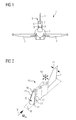
- FIG. 1 shows a front view of an aircraft 1, which is characterized by particularly high maneuverability.
- the aircraft 1 has a fuselage 2 and wings 3 defining the span.
- the aircraft 1 further has a vertical stabilizer 4 and an air brake 5 mounted on the upper side of the fuselage 2, which comprises a brake flap 6 which can be folded out into the air stream flowing against the vertical stabilizer 4.
- a centrally disposed slot-like passage 7 is formed in a fuselage region of the brake flap 6, however, two eccentrically arranged slot-like bushings 8 are provided.
- FIG. 2 shows a perspective view of the deployed brake flap 6, which is flowed by an air flow 9 with flow velocity u ⁇ along a longitudinal axis 10.
- air swirls 12 are released, which form a turbulent wake 13, which lead to fluctuations 14 of the speed and the pressure in the wake 13.
- the structural vibrations 15 may include both torsion components and bending components.
- the front side of the brake flap 6, which is flown by the air flow 9, is similar in shape to a truncated cone 17 placed on a rectangular base surface 16 from the outer shape.
- FIG. 3 is a plan view of the flowed through the air flow 9 front of the brake flap 6 is shown. Also in FIG. 3 is the base 16 and the patch on the base 16 truncated cone 17 recognizable.
- the brake flap 6 is formed symmetrically with respect to a central longitudinal axis 18. In the area of a fuselage end 19 of the brake flap 6, the passage 7 is arranged, while the bushings 8 are located in the region of a fuselage end 20.
- the base 16 of the brake flap 6 has a ready B and a length L.
- the dimensions of the passage 7 preferably has a trapezoidal shape.
- the fuselage-side base of the bushing 7 in particular has a width in the range between 0.25 B and 0.35 B of the base width B of the brake flap 6, while the width of the fuselage side of the bushing 7 preferably in the range between 0.15 B and 0, 25 B is located.
- the length of the passage 7 is preferably in the range between 0.25 L and 0.35 L of the length L of the brake flap 6.
- the distance of the fuselage end of the bushing 7 should be between 0.02 L and 0.05 L from the fumetto end ,
- the hull near bushings 8 preferably have a rectangular cross-section with a width between 0.1 B and 0.2 B and a length between 0.25 L and 0.35 L.
- the hull-side end of the bushings 8 is preferably at a distance from the fuselage End 20, which is between 0.05 L and 0.1 L. For structural reasons, it may also be necessary to arrange the bushings 8 at a distance of up to 0.3 L from the end 20 near the fuselage.
- the exact position and size of the bushings 7 and 8 and possibly also the number of bushings 8 depend on the respective size and design of the brake flap 6, in particular on the expected caster with vortex shedding and the other currents around the fuselage 2 and the wings 3 ,
- the configuration of the bushings 7 and 8 depends on the desired degree of reduction and the acceptable loss of aerodynamic drag of the brake flap 6.
- the total cross-sectional area of the passages 7 and 8 formed in the brake flap 6 should not be greater than 25 percent of the cross-sectional area of the brake flap 6. If necessary, can the loss of aerodynamic resistance can be compensated by increasing the cross-sectional area of the brake flap 6.
- time series of the pressure difference between the pressure at the measuring location and the ambient pressure at different positions of the vertical stabilizer 4 were recorded by transient pressure sensors.
- the positioning of the pressure sensors is in FIG. 4 shown.
- the wind tunnel model used was equipped with a total of eighteen pressure sensors.
- the pressure sensors were arranged at opposite locations on both sides of the vertical stabilizer 4.
- the measuring locations are FIG. 4 characterized by the positions P1 to P17.
- the relative pressure at one of the measuring locations was converted by reference to the dynamic pressure upstream of the vertical stabilizer 4 into a pressure coefficient as a dimensionless variable.
- the mean value and the standard deviation c prms were calculated in the form of the mean square deviation.
- the value of the standard deviation c prms therefore stands for the fluctuation intensity of the pressure coefficient.
- High values of the standard deviation c prms mean a high aerodynamic excitation, which is associated with a high structural dynamic load.
- FIG. 5 shows a diagram in which the standard deviation c prms is plotted against the angle of attack ⁇ .
- a load curve 21 indicates the course of the standard deviation c prms when the brake flap 6 is applied.
- ⁇ ⁇ 10 ° Up to an angle of attack of about ⁇ ⁇ 10 °, the load curve 22 is at a constant value above the load curve 21. Above an angle of about ⁇ ⁇ 10 °, the load curve 22 increases significantly and reaches at an angle of about ⁇ ⁇ 24 ° absolute maximum. With further increasing angle of attack ⁇ falls the load curve 22 steeply before the load curve 22 of the load curve 21 following increases again.
- FIG. 6 is now next to the load curve 21 and the load curve 22, a further load curve 23 located, which reproduces the course of the standard deviation c pmrs when using the brake flap 6 with the bushings 7 and 8.
- a comparison of the load curves 22 and 23 shows that the load due to the bushings 7 and 8 is substantially reduced over the entire pitch range. On average, the reduction is about 30 to 40 percent. Accordingly, the structural dynamic loads of the vertical stabilizer 4 are reduced.
- FIGS. 9 to 11 contain diagrams in which the spectral power density Sc p of the pressure coefficient fluctuations at the position P13 on the tail unit 4 is plotted against the reduced frequency k.
- the reduced frequency is equal to the divided by the flow velocity product of the frequency of Druckbeiwertschwankungen with the reference wing depth of the tail 4.
- FIG. 9 in particular shows a power spectrum 25 of the pressure coefficient fluctuations when using a brake flap without feedthroughs.
- the power spectrum 25 has fluctuation peaks 26 associated with dominant frequencies.
- Another in FIG. 9 27 shows the spectral distribution of the pressure coefficient fluctuations in the case of the brake flap 6 with fuselage close feedthroughs 8 and the hull-distal feedthrough 7 FIG. 9 It can be seen that the power spectrum 27 in the area of the fluctuation spikes is more than an order of magnitude below the line spectrum 25.
- the corresponding power spectra 25 and 27 show that not only the overall fluctuation level, but also, above all, the fluctuation associated with the vortex shifts, are significantly reduced with a dominant frequency.
- the power peaks associated with a dominant frequency in the pressure spectra therefore decrease considerably.
- the slit-shaped bushings 7 and 8 in the brake flap 6 are to be adapted in size and position to the prevailing geometry of the brake flap 6 and the acting flow conditions, in particular the periodic Wirbelnachlauf and the occurrence of split leading edge vortices.
- FIG. 12 The reduction in air resistance associated with the provision of the bushings 7 and 8 is small, as is FIG. 12 can be read.
- the relative flow resistance coefficient c wrel is always based on the flow resistance coefficient of a brake flap without feedthroughs.
- a resistance curve 30 indicates the relative resistance change for the case, that only the fuselage bushings 8 are present.
- Another resistance curve 31 illustrates the case that only the hump remote passage 7 is formed in the brake flap.
Abstract
Description
Die Erfindung betrifft eine Vorrichtung zum Erzeugen von aerodynamischem Widerstand an einem Luftfahrzeug mit wenigstens einer Bremsklappe, die in einen ein Seitenleitwerk anströmenden Luftstrom ausklappbar ist.The invention relates to a device for generating aerodynamic resistance on an aircraft with at least one brake flap, which can be folded out into an air stream flowing in a vertical tail.
Die Erfindung betrifft ferner ein mit der Vorrichtung zum Erzeugen von aerodynamischem Widerstand ausgestattetes Luftfahrzeug sowie ein Verfahren zum Erzeugen von aerodynamischem Widerstand.The invention further relates to an aircraft equipped with the device for generating aerodynamic resistance and to a method for generating aerodynamic resistance.
Eine derartige Vorrichtung, ein derartiges Luftfahrzeug und ein derartiges Verfahren sind aus der Veröffentlichung
Der erfliegbare Bereich (Flugenveloppe) hochmanövrierfähiger Flugzeuge wird typischerweise durch dynamische aeroelastische Phänomene wie Schüttelerscheinungen (buffeting), Brummen (buzz) und Flattern von Tragflügeln und Leitwerken begrenzt. Tragflügel oder Flügelkomponenten kleiner Streckung und mäßiger bis hoher Vorderkantenpfeilung, wie sie typischerweise bei derartigen Flugzeugen Verwendung finden, erzeugen schon bei mäßigen Anstellwinkel ein Strömungsfeld mit geordneten Vorderkantenwirbeln. Die Bildung von Vorderkantenwirbeln ist einerseits gewollt, da gegenüber einer ausschließlich anliegenden Strömung ein deutlicher Auftriebsgewinn sowie eine Erhöhung des nutzbaren Anstellwinkelbereichs zur Steigerung der Manövrierfähigkeit erzielt werden. Andererseits kommt es bei höheren Anstellwinkeln aufgrund des steigenden adversen Gradienten zu einer Strukturveränderung im Wirbelkern, dem Wirbelaufplatzen. Dies äußert sich in einer abrupten Erweiterung des Wirbelkernquerschnitts verbunden mit einer stromab des Aufplatzpunkts hochturbulenten Strömung. Eine dabei vorherrschende spiralförmige Instabilität bewirkt starke engbandige Geschwindigkeits- und Druckfluktuationen. Diese frequenzspezifischen Fluktuationen können direkt oder durch Induktion zu Schüttelerscheinungen an Flugzeug- oder Strukturkomponenten führen. Die beispielsweise am Seitenleitwerk hervorgerufenen instationären Luftkräfte führen typischerweise zu einer Strukturanregung in den Moden der ersten Biegung und/oder ersten Torsion. Je nach Anregungsintensität kann dies eine Begrenzung der Flugenveloppe für den Bereich hoher Anstellwinkel zur Folge haben.The flyable area (flight envelope) of high maneuverable aircraft is typically characterized by dynamic aeroelasticity Phenomena such as buffeting, hum (buzz) and flapping of airfoils and tail units are limited. Small wing aerofoils and moderate to high leading edge sweep, as typically used in such aircraft, produce a flow field with ordered leading edge vortices even at moderate angles of attack. On the one hand, the formation of leading edge vortices is intentional, since a distinct increase in lift and an increase in the usable angle of attack range for increasing maneuverability are achieved in contrast to an exclusively applied flow. On the other hand, at higher angles of incidence, due to the increasing adversarial gradient, there is a structural change in the vortex core, the vortex burst. This manifests itself in an abrupt expansion of the vortex core cross section associated with a highly turbulent flow downstream of the point of deployment. A prevailing helical instability causes strong narrow-band velocity and pressure fluctuations. These frequency-specific fluctuations may result, directly or by induction, in shaking phenomena on aircraft or structural components. The transient air forces caused, for example, on the vertical stabilizer typically result in a structural excitation in the modes of the first bend and / or first torsion. Depending on the excitation intensity, this may result in a limitation of the flight envelope for the high angle of attack range.
Aus der
Ausgehend von diesem Stand der Technik liegt der Erfindung daher die Aufgabe zugrunde, eine Vorrichtung zum Erzeugen von aerodynamischem Widerstand in einem ein Seitenleitwerk eines Luftfahrzeugs anströmenden Luftstrom zu schaffen, das den erfliegbaren Bereich möglichst unbeeinträchtigt lässt. Der Erfindung liegt ferner die Aufgabe zugrunde, ein entsprechendes Verfahren zu schaffen.Based on this prior art, the invention is therefore based on the object, a device for generating To provide aerodynamic drag in an airflow flowing into a rudder of an aircraft, which leaves the unreachable area as unimpaired. The invention is also based on the object to provide a corresponding method.
Diese Aufgaben werden durch eine Vorrichtung mit den Merkmalen des unabhängigen Anspruchs gelöst. In davon abhängigen Ansprüchen sind vorteilhafte Ausgestaltungen und Weiterbildungen angegeben.These objects are achieved by a device having the features of the independent claim. In dependent claims advantageous embodiments and developments are given.
Bei der Vorrichtung und dem Verfahren wird eine Bremsklappe verwendet, die in den das Seitenleitwerk anströmenden Luftstrom ausklappbar ist und mit wenigstens einer Durchführung versehen ist, die der Impulserhöhung der Luft im Windschatten der Bremsklappe dient. Versuche haben gezeigt, dass sich durch derartige Durchführungen die Turbulenzen im Nachlauf der Bremsklappe herabsetzen und die periodischen Wirbelablösungen verringern lassen. Dadurch können die strukturdynamischen Belastungen des Seitenleitwerks gering gehalten werden, so dass der erfliegbare Bereich durch das Ausfahren der Bremsklappe kaum eingeschränkt wird.In the apparatus and the method, a brake flap is used, which is in the tailstream flowing air stream is deployed and provided with at least one passage, which serves to increase the pulse of air in the lee of the brake flap. Experiments have shown that reduce through such a passage, the turbulence in the wake of the brake flap and reduce the periodic vortex shedding. As a result, the structure dynamic loads of the vertical stabilizer can be kept low, so that the recoverable area is hardly limited by the extension of the brake flap.
Bei einer Ausführungsform der Vorrichtung nimmt die Dicke der Bremsklappe von einem rumpfnahen zu einem rumpffernen Ende hin ab. Dadurch können die Biegemomente zum rumpffernen Ende hin klein gehalten werden.In one embodiment of the device, the thickness of the brake flap decreases from a fuselage close to a fuselage far end. As a result, the bending moments can be kept small to the fuselage far end.
Bei einer weiteren Ausführungsform ist die wenigstens eine Durchführung von einem in der Bremsklappe ausgebildeten Schlitz gebildet, der in Längsrichtung von einem rumpfnahen Ende zu einem rumpffernen Ende verläuft. Es hat sich gezeigt, dass sich insbesondere durch Schlitze, die sich von einem rumpfnahen Ende zu einem rumpffernen Ende erstrecken, die strukturdynamische Belastung des Seitenleitwerks erheblich reduzieren lässt.In a further embodiment, the at least one passage is formed by a slit formed in the brake flap which extends in the longitudinal direction from a fuselage close end to a fuselage far end. It has been found that, in particular through slots which extend from a fuselage close to a fuselage end, the structural dynamic load of the vertical stabilizer can be significantly reduced.
Wenn die Durchführung im rumpfnahen Bereich der Bremsklappe angeordnet ist, wird im hohen und sehr hohen Anstellwinkelbereich eine Abmilderung der strukturdynamischen Belastungen des Seitenleitwerks erreicht. Die Durchführung weist dabei vorzugsweise ein trapezförmiges Querschnittsprofil auf, dessen rumpfnahe Unterseite eine Breite zwischen 0,25 B und 0,35 B einer Basisbreite B der Bremsklappe beträgt, während eine rumpfferne Oberseite der Durchführung eine Breite zwischen 0,15 B und 0,2 B der Basisbreite B der Bremsklappe aufweist. Unter Basisbreite B der Bremsklappe soll dabei die Breite der Bremsklappe am rumpfnahen Ende verstanden werden. Die Länge L der Durchführung soll ferner zwischen 0,25 L und 0,35 L der Länge der Bremsklappe liegen.If the bushing is arranged in the fuselage region of the brake flap, a reduction of the structural dynamic loads of the vertical stabilizer is achieved in the high and very high angle of attack range. The feedthrough preferably has a trapezoidal cross-sectional profile whose underside close to the fuselage has a width between 0.25 B and 0.35 B of a base width B of the brake flap, while a fuselage top of the feedthrough has a width between 0.15 B and 0.2 B the base width B of the brake flap has. Base width B of the brake flap should be understood to mean the width of the brake flap at the fuselage end. The length L of the implementation should also be between 0.25 L and 0.35 L of the length of the brake flap.
Bei kleineren Anstellwinkeln lässt sich dagegen die strukturdynamische Belastung des Seitenleitwerks verringern, in dem in einem rumpfnahen Bereich der Bremsklappe wenigstens zwei Durchführungen vorgesehen werden. Die Durchführungen weisen vorzugsweise einen rechteckförmigen Querschnitt auf. Die Breite der Durchführung beträgt dabei vorzugsweise zwischen 0,1 B und 0,2 B der Basisbreite B der Bremsklappe, während die Länge L der Durchführung zwischen 0,25 L und 0,35 L der Länge der Bremsklappe beträgt.For smaller angles of attack, on the other hand, it is possible to reduce the structural dynamic load of the vertical stabilizer, in which at least two bushings are provided in a region of the brake flap close to the fuselage. The bushings preferably have a rectangular cross-section. The width of the bushing is preferably between 0.1 B and 0.2 B of the base width B of the brake flap, while the length L of the implementation is between 0.25 L and 0.35 L of the length of the brake flap.
Weitere Vorteile und Eigenschaften der Erfindung gehen aus der nachfolgenden Beschreibung hervor, in der Ausführungsbeispiele der Erfindung anhand der Zeichnung im Einzelnen erläutert werden. Es zeigen:
Figur 1- eine Vorderansicht eines Hochleistungsflugzeugs mit ausgeschlagener Luftbremse;
Figur 2- eine perspektivische Ansicht einer ausgeschlagener Luftbremse einschließlich dem auf ein Seitenleitwerk des Hochleistungsflugzeugs wirkenden Nachlauf;
Figur 3- eine Aufsicht auf die Bremsklappe der Luftbremse;
Figur 4- eine Seitenansicht eines Seitenleitwerks mit den bei einer Messung verwendeten Messpunkten;
Figur 5- ein Diagramm, in das die flächengemittelte Druckschwankungsintensität als Funktion des Anstellwinkels für die Fälle mit und ohne Ausschlag der Luftbremse dargestellt ist;
Figur 6- ein
Figur 5 Figur 7- ein
Figur 5 Figur 8- ein
Figur 5 - Figur 9
- ein Diagramm, mit einem Leistungsspektrum der Druckschwankungen am Seitenleitwerk bei Einsatz einer Bremsklappe mit einer rumpffernen und zwei rumpfnahen Durchführungen;
Figur 10- ein Diagramm, mit einem Leistungsspektrum der Druckschwankungen am Seitenleitwerk bei Einsatz einer Bremsklappe mit einer rumpffernen Durchführung;
Figur 11- ein Diagramm, mit einem Leistungsspektrum der Druckschwankungen am Seitenleitwerk bei Einsatz einer Bremsklappe mit rumpfnahen Durchführung; und
Figur 12- ein Diagramm, das die relative Änderung des Strömungswiderstandskoeffizienten für verschiedene Ausführungen der Bremsklappe zeigt.
- FIG. 1
- a front view of a high-performance aircraft with knocked-out air brake;
- FIG. 2
- a perspective view of a worn-out air brake including acting on a rudder of the high-performance aircraft caster;
- FIG. 3
- a view of the airbrake brake flap;
- FIG. 4
- a side view of a rudder with the measuring points used in a measurement;
- FIG. 5
- a diagram in which the area average pressure fluctuation intensity as a function of the angle of attack for the cases with and without rash of the air brake is shown;
- FIG. 6
- one
FIG. 5 corresponding diagram illustrating the function of slot-shaped passages in the brake flap; - FIG. 7
- one
FIG. 5 corresponding diagram showing the effect of a hull-distant implementation in the brake flap; - FIG. 8
- one
FIG. 5 corresponding diagram showing the effect of arranged in a fuselage region of the brake flap bushings; and - FIG. 9
- a diagram, with a performance spectrum of the pressure fluctuations on the vertical stabilizer when using a brake flap with a hull distant and two fuselage ducts;
- FIG. 10
- a diagram with a performance spectrum of the pressure fluctuations on the vertical stabilizer when using a brake flap with a hull-distant implementation;
- FIG. 11
- a diagram, with a performance spectrum of pressure fluctuations on the vertical stabilizer when using a brake flap with close to the hull implementation; and
- FIG. 12
- a diagram showing the relative change in the flow resistance coefficient for different versions of the brake flap.
Es sei angemerkt, dass die von der Luftströmung 9 angeströmte Vorderseite der Bremsklappe 6 von der äußeren Form her einem auf eine rechteckige Grundfläche 16 aufgesetzten Kegelstumpf 17 gleicht.It should be noted that the front side of the
In
Die Grundfläche 16 der Bremsklappe 6 weist eine Bereite B und eine Länge L auf. Die Abmessungen der Durchführung 7 weist vorzugsweise eine trapezförmige Gestalt auf. Die rumpfseitige Basis der Durchführung 7 weist insbesondere eine Breite im Bereich zwischen 0,25 B und 0,35 B der Basisbreite B der Bremsklappe 6 auf, während die Breite der rumpffernen Seite der Durchführung 7 vorzugsweise im Bereich zwischen 0,15 B und 0,25 B liegt. Die Länge der Durchführung 7 liegt vorzugsweise im Bereich zwischen 0,25 L und 0,35 L der Länge L der Bremsklappe 6. Der Abstand des rumpffernen Endes der Durchführung 7 sollte zwischen 0,02 L und 0,05 L vom rumpffernen Ende entfernt sein.The
Die rumpfnahen Durchführungen 8 weisen bevorzugt einen rechteckförmigen Querschnitt auf mit einer Breite zwischen 0,1 B und 0,2 B und einer Länge zwischen 0,25 L und 0,35 L. Das rumpfseitige Ende der Durchführungen 8 ist vorzugsweise in einem Abstand zum rumpfnahen Ende 20 angeordnet, der zwischen 0,05 L und 0,1 L liegt. Aus konstruktiven Gründen kann es auch erforderlich sein, die Durchführungen 8 in einem Abstand von bis zu 0,3 L vom rumpfnahen Ende 20 anzuordnen.The hull near
Die exakte Position und Größe der Durchführungen 7 und 8 sowie gegebenenfalls auch die Anzahl der Durchführungen 8 hängen von der jeweiligen Größe und Gestaltung der Bremsklappe 6, insbesondere von dem zu erwartenden Nachlauf mit Wirbelablösung sowie der sonstigen Strömungen um den Rumpf 2 und die Tragflächen 3 ab. Außerdem hängt die Konfiguration der Durchführungen 7 und 8 von dem gewünschten Grad der Abminderung und der hinnehmbaren Einbuße an aerodynamischem Widerstand der Bremsklappe 6 ab. In der Regel sollte die gesamte Querschnittsfläche der in der Bremsklappe 6 ausgebildeten Durchführungen 7 und 8 nicht größer als 25 Prozent der Querschnittsfläche der Bremsklappe 6 sein. Gegebenenfalls kann die Einbuße an aerodynamischem Widerstand durch eine Vergrößerung der Querschnittsfläche der Bremsklappe 6 ausgeglichen werden.The exact position and size of the
Zur Quantifizierung der aerodynamischen Anregungen wurden Zeitreihen der Druckdifferenz zwischen dem Druck am Messort und dem Umgebungsdruck an verschiedenen Positionen des Seitenleitwerks 4 durch instationäre Drucksensoren aufgenommen. Die Positionierung der Drucksensoren ist in
In
Durch die spezifische Konfiguration der Durchführungen 7 und 8 ist es auch möglich, die Abminderungen der aerodynamischen Anregung auf unterschiedliche Anstellwinkelbereiche abzustimmen, die jeweils unterschiedlichen Strömungsformen des Nachlaufs 13 der Bremsklappe 6 zugeordnet werden können. Im hohen und sehr hohen Anstellwinkelbereich, insbesondere bei α > 12°, bewirkt die Impulserhöhung mittels der oberen Durchführung 7 eine Abminderung, da hier eine axial gerichtete Wirbelströmung vorherrscht. Diese resultiert aus den mit zunehmenden Anstellwinkel α immer geringeren effektiven Anströmwinkel an den Außenkanten 11 der Bremsklappe 6. Um dies zu verdeutlichen, ist in
Im niedrigen und mäßigen Anstellwinkelbereich, insbesondere bei Anstellwinkel bis α ≈ 12° herrscht dagegen eine periodische Wirbelablösung mit vertikal gerichteten Wirbelachsen vor, wie es dem Nachlauf 13 eines stumpfen Körpers entspricht. Die mit dieser Form des Nachlaufs 13 verbundene dynamische Anregung kann durch die zwei schlitzförmigen Durchführungen 8 abgemindert werden. Diese Abminderung lässt sich anhand
Neben den in den
In den
Es sei angemerkt, dass die Abminderung der Fluktuationsspitzen bei größeren Anstellwinkeln ηAB noch stärker ausgeprägt ist.It should be noted that the reduction of the fluctuation peaks is even more pronounced for larger angles of incidence η AB .
Durch die Verwendung der schlitzförmigen Durchführungen 7 und 8 in der Bremsklappe 6 kann demnach die aerodynamische Anregung an den im Nachlauf 13 befindlichen Strukturelementen bei Hochleistungsflugzeugen wesentlich vermindert werden. Die schlitzförmigen Durchführungen 7 und 8 der Bremsklappe 6 sind dabei in ihrer Größe und Position an die vorherrschende Geometrie der Bremsklappe 6 und die einwirkenden Strömungsverhältnisse, insbesondere dem periodischen Wirbelnachlauf und das Auftreten von aufgeplatzten Vorderkantenwirbeln anzupassen.By using the slit-shaped
Die durch mit dem Vorsehen der Durchführungen 7 und 8 verknüpfte Verringerung des Luftwiderstands ist gering, wie von
Abschließend sei noch darauf hingewiesen, dass Merkmale und Eigenschaften, die im Zusammenhang mit einem bestimmten Ausführungsbeispiel beschrieben worden sind, auch mit einem anderen Ausführungsbeispiel kombiniert werden können, außer wenn dies aus Gründen der Kompatibilität ausgeschlossen ist.Finally, it should be noted that features and properties that have been described in connection with a particular embodiment can also be combined with another embodiment, except where this is excluded for reasons of compatibility.
Schließlich wird noch darauf hingewiesen, dass in den Ansprüchen und in der Beschreibung der Singular den Plural einschließt, außer wenn sich aus dem Zusammenhang etwas anderes ergibt. Insbesondere wenn der unbestimmte Artikel verwendet wird, ist sowohl der Singular als auch der Plural gemeint.Finally, it should be noted that in the claims and in the description, the singular includes the plural unless the context indicates otherwise. In particular, when the indefinite article is used, it means both the singular and the plural.
Claims (12)
dadurch gekennzeichnet, dass
die wenigstens eine Bremsklappe (6) mit wenigstens einer Durchführung (7, 8) versehen ist, die der Impulserhöhung der Luft im Windschatten der Bremsklappe (6) dient.Device for generating aerodynamic drag on an aircraft having at least one brake flap (6) which can be folded out into a stream of air that is flowing in a vertical tail,
characterized in that
the at least one brake flap (6) having at least one passage (7, 8) is provided, which serves to increase the pulse of the air in the lee of the brake flap (6).
dadurch gekennzeichnet, dass
die Dicke der Bremsklappe (6) von einem rumpfnahen Ende (20) zu einem rumpffernen Ende (19) abnimmt.Device according to claim 1,
characterized in that
the thickness of the brake flap (6) decreases from a fuselage close end (20) to a fuselage far end (19).
dadurch gekennzeichnet, dass
die wenigstens eine Durchführung (7, 8) von einem in der Bremsklappe (6) ausgebildeten Schlitz gebildet ist, der entlang einer Längsachse (18) von einem rumpfnahen Ende (20) zu einem rumpffernen Ende (19) verläuft.Apparatus according to claim 1 or 2,
characterized in that
the at least one passage (7, 8) is formed by a slot formed in the brake flap (6) which extends along a longitudinal axis (18) from a fuselage close end (20) to a fuselage far end (19).
dadurch gekennzeichnet, dass
eine Durchführung (7) im rumpffernen Bereich der Bremsklappe (6) angeordnet ist.Apparatus according to claim 1 or 2
characterized in that
a passage (7) in the fuselage region of the brake flap (6) is arranged.
dadurch gekennzeichnet, dass
die Durchführung (7) im rumpffernen Bereich der Bremsklappe (6) ein trapezförmiges Querschnittsprofil aufweist.Device according to claim 4,
characterized in that
the passage (7) has a trapezoidal cross-sectional profile in the region of the brake flap (6) remote from the fuselage.
dadurch gekennzeichnet, dass
eine rumpfnahe Unterseite der Durchführung (7) eine Breite zwischen 0,25 B und 0,35 B einer Basisbreite B der Bremsklappe (6) und eine rumpfferne Oberseite der Durchführung (7) eine Breite zwischen 0,15 B und 0,2 B der Basisbreite B der Bremsklappe (6) aufweist und dass die Länge der Durchführung zwischen 0,25 L und 0,35 L der Länge L der Bremsklappe (6) beträgt.Device according to claim 5,
characterized in that
a fuselage underside of the passage (7) has a width between 0.25 B and 0.35 B of a base width B of the brake flap (6) and a fuselage upper side of the passage (7) has a width between 0.15 B and 0.2 B of the base width B of the brake flap (6) and that the length of the passage between 0.25 L and 0.35 L of Length L of the brake flap (6) is.
dadurch gekennzeichnet, dass
wenigstens eine Durchführung (8) im rumpfnahen Bereich der Bremsklappe (6) angeordnet ist.Device according to one of the claims 1 to 5
characterized in that
at least one passage (8) in the fuselage near the brake flap (6) is arranged.
dadurch gekennzeichnet, dass
die Bremsklappe (6) in einem rumpfnahen Bereich wenigstens zwei Durchführungen (8) aufweist.Device according to claim 6
characterized in that
The brake flap (6) has at least two passages (8) in a region close to the fuselage.
dadurch gekennzeichnet, dass
die Durchführungen (8) eine rechteckförmigen Querschnitt aufweisen und dass eine Breite einer Durchführung (8) zwischen 0,1 B und 0,2 B der Basisbreite B der Bremsklappe (6) liegt und dass eine Länge der Durchführung (8) zwischen 0,25 L und 0,35 L der Länge der Bremsklappe (6) beträgt.Device according to claim 7,
characterized in that
the passages (8) have a rectangular cross-section and that a width of a passage (8) is between 0.1 B and 0.2 B of the base width B of the brake flap (6) and that a length of the passage (8) is between 0.25 L and 0.35 L of the length of the brake flap (6) is.
dadurch gekennzeichnet, dass
die Vorrichtung nach einem der Ansprüche 1 bis 8 ausgestaltet ist.An aircraft with a device for generating aerodynamic resistance by means of a brake flap (6) which can be folded out into an air stream surrounding the aircraft
characterized in that
the device according to one of claims 1 to 8 is configured.
dadurch gekennzeichnet, dass
sich eine entlang der Längsachse (10) des Luftfahrzeugs erstreckende Symmetrieebene der Bremsklappe (6) mit eine sich entlang der Längsachse (10) des Luftfahrzeugs erstreckenden Symmetrieebene des Seitenleitwerks (4) deckt.Aircraft according to claim 9.
characterized in that
is a along the longitudinal axis (10) of the aircraft extending plane of symmetry of the brake flap (6) with a along the longitudinal axis (10) of the aircraft extending symmetry plane of the vertical stabilizer (4) covers.
dadurch gekennzeichnet, dass
eine Bremsklappe einer Vorrichtung nach einem der Ansprüche 1 bis 8 ausgeklappt wird.Method for generating aerodynamic drag on an aircraft, in which a brake flap is unfolded into a stream of air flowing in a vertical tail,
characterized in that
a brake flap of a device according to one of claims 1 to 8 is unfolded.
Priority Applications (4)
| Application Number | Priority Date | Filing Date | Title |
|---|---|---|---|
| EP08166306A EP2174867A1 (en) | 2008-10-10 | 2008-10-10 | Device for producing aerodynamic resistance in an airplane |
| EP09744359A EP2337737A1 (en) | 2008-10-10 | 2009-10-09 | Device for generating aerodynamic resistance on an aircraft |
| PCT/EP2009/063172 WO2010040828A1 (en) | 2008-10-10 | 2009-10-09 | Device for generating aerodynamic resistance on an aircraft |
| US13/082,075 US20110233330A1 (en) | 2008-10-10 | 2011-04-07 | Device for generating aerodynamic resistance on an aircraft |
Applications Claiming Priority (1)
| Application Number | Priority Date | Filing Date | Title |
|---|---|---|---|
| EP08166306A EP2174867A1 (en) | 2008-10-10 | 2008-10-10 | Device for producing aerodynamic resistance in an airplane |
Publications (1)
| Publication Number | Publication Date |
|---|---|
| EP2174867A1 true EP2174867A1 (en) | 2010-04-14 |
Family
ID=40328503
Family Applications (2)
| Application Number | Title | Priority Date | Filing Date |
|---|---|---|---|
| EP08166306A Withdrawn EP2174867A1 (en) | 2008-10-10 | 2008-10-10 | Device for producing aerodynamic resistance in an airplane |
| EP09744359A Withdrawn EP2337737A1 (en) | 2008-10-10 | 2009-10-09 | Device for generating aerodynamic resistance on an aircraft |
Family Applications After (1)
| Application Number | Title | Priority Date | Filing Date |
|---|---|---|---|
| EP09744359A Withdrawn EP2337737A1 (en) | 2008-10-10 | 2009-10-09 | Device for generating aerodynamic resistance on an aircraft |
Country Status (3)
| Country | Link |
|---|---|
| US (1) | US20110233330A1 (en) |
| EP (2) | EP2174867A1 (en) |
| WO (1) | WO2010040828A1 (en) |
Families Citing this family (1)
| Publication number | Priority date | Publication date | Assignee | Title |
|---|---|---|---|---|
| NL2008049C2 (en) * | 2011-12-28 | 2013-07-01 | Jan Louis Kroes | ROAD AIRCRAFT OR FLY SIMULATOR, ADJUSTABLE TROUSER, COMPUTER PROGRAM PRODUCT AND METHOD. |
Citations (3)
| Publication number | Priority date | Publication date | Assignee | Title |
|---|---|---|---|---|
| US2138949A (en) * | 1937-05-08 | 1938-12-06 | Weidman Fred | Flight retarder for airships |
| DE718322C (en) * | 1936-07-26 | 1942-03-09 | Forschungsanstalt Fuer Segelfl | Dive brake |
| US4165849A (en) | 1977-12-14 | 1979-08-28 | Anthony Fox | Combination air brake and engine shield for aircraft |
Family Cites Families (13)
| Publication number | Priority date | Publication date | Assignee | Title |
|---|---|---|---|---|
| US1159720A (en) * | 1911-08-22 | 1915-11-09 | John Thomas Simpson | Aeroplane. |
| US1274037A (en) * | 1917-07-06 | 1918-07-30 | John C Hasbrouck Jr | Flight-retarder or brake for airships. |
| US1773521A (en) * | 1929-09-16 | 1930-08-19 | George H Davis | Mechanism for operating aeroplane brakes and similar structures |
| US1834149A (en) * | 1930-03-28 | 1931-12-01 | Robert H Goddard | Means for decelerating aircraft |
| US2344520A (en) * | 1940-09-09 | 1944-03-21 | Joseph Varro | Airplane air brake |
| US2549020A (en) * | 1949-02-10 | 1951-04-17 | United Aircraft Corp | Automatic speed controller |
| US2738147A (en) * | 1952-04-04 | 1956-03-13 | Verne L Leech | Means for turning and braking jet propelled aircraft |
| US2698149A (en) * | 1952-05-02 | 1954-12-28 | Ernest J Greenwood | Aircraft speed retarding device |
| US2943823A (en) * | 1954-06-22 | 1960-07-05 | North American Aviation Inc | Trim correction system for high speed vehicles |
| US4372507A (en) * | 1977-03-02 | 1983-02-08 | Rockwell International Corporation | Selectively actuated flight simulation system for trainer aircraft |
| FR2728535A1 (en) * | 1994-12-26 | 1996-06-28 | Aerospatiale | VARIABLE SLOTTED AEROBRAKE FOR AIRCRAFT WING |
| DE102006025752A1 (en) * | 2006-05-31 | 2007-12-06 | Airbus Deutschland Gmbh | Method and apparatus for generating aerodynamic drag on an aircraft |
| EP2259966B1 (en) * | 2008-03-31 | 2012-09-12 | Honda Patents & Technologies North America, LLC | Aerodynamic braking device for aircraft |
-
2008
- 2008-10-10 EP EP08166306A patent/EP2174867A1/en not_active Withdrawn
-
2009
- 2009-10-09 WO PCT/EP2009/063172 patent/WO2010040828A1/en active Application Filing
- 2009-10-09 EP EP09744359A patent/EP2337737A1/en not_active Withdrawn
-
2011
- 2011-04-07 US US13/082,075 patent/US20110233330A1/en not_active Abandoned
Patent Citations (3)
| Publication number | Priority date | Publication date | Assignee | Title |
|---|---|---|---|---|
| DE718322C (en) * | 1936-07-26 | 1942-03-09 | Forschungsanstalt Fuer Segelfl | Dive brake |
| US2138949A (en) * | 1937-05-08 | 1938-12-06 | Weidman Fred | Flight retarder for airships |
| US4165849A (en) | 1977-12-14 | 1979-08-28 | Anthony Fox | Combination air brake and engine shield for aircraft |
Non-Patent Citations (2)
| Title |
|---|
| BREITSAMTER C: "Airbrake induced fin buffet loads on fighter aircraft", ICAS 2006, 25TH INTERNATIONAL CONGRESS OF THE AERONAUTICAL SCIENCE,, 1 January 2006 (2006-01-01), pages 1 - 11, XP009112042 * |
| BREITSAMTER, C.: "Airbrake induced fin buffet loads on fighter aircraft", ICAS 2006, 25TH INTERNATIONAL CONGRESS OF THE AERONAUTICAL SCIENCE, 2006 |
Also Published As
| Publication number | Publication date |
|---|---|
| EP2337737A1 (en) | 2011-06-29 |
| WO2010040828A1 (en) | 2010-04-15 |
| US20110233330A1 (en) | 2011-09-29 |
Similar Documents
| Publication | Publication Date | Title |
|---|---|---|
| EP1112928B1 (en) | Airfoil with performance enhancing trailing edge | |
| DE19926832B4 (en) | Subsonic aircraft preferably with swept-up wings | |
| DE102008052858B9 (en) | Profile of a rotor blade and rotor blade of a wind turbine | |
| DE2555718C3 (en) | Airplane with two backward-swept wings arranged one above the other | |
| DE2149956C3 (en) | High lift wing | |
| EP2064116B1 (en) | Aerodynamic body and carrier wing comprising an aerodynamic body for influencing post-turbulences | |
| EP2217491B1 (en) | Use of a wingtip extension for reduction of vortex drag in aircraft | |
| DE19719922C1 (en) | Device for influencing a root flow | |
| EP2959161A1 (en) | Rotor blade of a wind turbine | |
| DE102009019542A1 (en) | Non-planar wing tail for airplanes of aircraft and wings with such wing tail | |
| EP2984334B1 (en) | Rotor blade of a wind turbine and wind turbine | |
| DE102008025152B4 (en) | Engine nacelle of an aircraft with a vortex generator arrangement | |
| EP2558363B1 (en) | High-lift system for an aircraft | |
| EP3399183B1 (en) | Rotor blade of a wind turbine | |
| DE19964114A1 (en) | Aerofoil section with lift-increasing trailing edge, in which trailing edge has spoilers on one or both sides to cause flow breakaway | |
| DE102010048266A1 (en) | Wing with a flow fence and plane with such wings | |
| EP2576987A1 (en) | Blade of a turbomachine, having passive boundary layer control | |
| EP2174867A1 (en) | Device for producing aerodynamic resistance in an airplane | |
| DE102007024372B4 (en) | Noise reduction device on a high lift system on the wing of an aircraft | |
| DE202015102982U1 (en) | Tragfläche particular of an aircraft | |
| DE102006025752A1 (en) | Method and apparatus for generating aerodynamic drag on an aircraft | |
| DE102018117398A1 (en) | Rotor blade for a wind turbine and wind turbine | |
| DE19909190C2 (en) | Airplane with at least one vortex generator per wing to reduce the vortex strength of the main wing vortex | |
| WO2015027990A1 (en) | Wing | |
| EP1506922B1 (en) | Method and aerodynamic body with device for reducing the drag of a limited supersonic flow region |
Legal Events
| Date | Code | Title | Description |
|---|---|---|---|
| PUAI | Public reference made under article 153(3) epc to a published international application that has entered the european phase |
Free format text: ORIGINAL CODE: 0009012 |
|
| AK | Designated contracting states |
Kind code of ref document: A1 Designated state(s): AT BE BG CH CY CZ DE DK EE ES FI FR GB GR HR HU IE IS IT LI LT LU LV MC MT NL NO PL PT RO SE SI SK TR |
|
| AX | Request for extension of the european patent |
Extension state: AL BA MK RS |
|
| AKY | No designation fees paid | ||
| STAA | Information on the status of an ep patent application or granted ep patent |
Free format text: STATUS: THE APPLICATION IS DEEMED TO BE WITHDRAWN |
|
| 18D | Application deemed to be withdrawn |
Effective date: 20101015 |
|
| REG | Reference to a national code |
Ref country code: DE Ref legal event code: R108 Effective date: 20110405 Ref country code: DE Ref legal event code: 8566 |