EP2174829A2 - Vehicle seat sliding apparatus - Google Patents
Vehicle seat sliding apparatus Download PDFInfo
- Publication number
- EP2174829A2 EP2174829A2 EP09171653A EP09171653A EP2174829A2 EP 2174829 A2 EP2174829 A2 EP 2174829A2 EP 09171653 A EP09171653 A EP 09171653A EP 09171653 A EP09171653 A EP 09171653A EP 2174829 A2 EP2174829 A2 EP 2174829A2
- Authority
- EP
- European Patent Office
- Prior art keywords
- rotation
- lock lever
- rail
- operating
- lower rail
- Prior art date
- Legal status (The legal status is an assumption and is not a legal conclusion. Google has not performed a legal analysis and makes no representation as to the accuracy of the status listed.)
- Granted
Links
Images

Classifications
-
- B—PERFORMING OPERATIONS; TRANSPORTING
- B60—VEHICLES IN GENERAL
- B60N—SEATS SPECIALLY ADAPTED FOR VEHICLES; VEHICLE PASSENGER ACCOMMODATION NOT OTHERWISE PROVIDED FOR
- B60N2/00—Seats specially adapted for vehicles; Arrangement or mounting of seats in vehicles
- B60N2/02—Seats specially adapted for vehicles; Arrangement or mounting of seats in vehicles the seat or part thereof being movable, e.g. adjustable
- B60N2/04—Seats specially adapted for vehicles; Arrangement or mounting of seats in vehicles the seat or part thereof being movable, e.g. adjustable the whole seat being movable
- B60N2/06—Seats specially adapted for vehicles; Arrangement or mounting of seats in vehicles the seat or part thereof being movable, e.g. adjustable the whole seat being movable slidable
- B60N2/08—Seats specially adapted for vehicles; Arrangement or mounting of seats in vehicles the seat or part thereof being movable, e.g. adjustable the whole seat being movable slidable characterised by the locking device
- B60N2/0881—Activation of the latches by the control mechanism
-
- B—PERFORMING OPERATIONS; TRANSPORTING
- B60—VEHICLES IN GENERAL
- B60N—SEATS SPECIALLY ADAPTED FOR VEHICLES; VEHICLE PASSENGER ACCOMMODATION NOT OTHERWISE PROVIDED FOR
- B60N2/00—Seats specially adapted for vehicles; Arrangement or mounting of seats in vehicles
- B60N2/02—Seats specially adapted for vehicles; Arrangement or mounting of seats in vehicles the seat or part thereof being movable, e.g. adjustable
- B60N2/04—Seats specially adapted for vehicles; Arrangement or mounting of seats in vehicles the seat or part thereof being movable, e.g. adjustable the whole seat being movable
- B60N2/06—Seats specially adapted for vehicles; Arrangement or mounting of seats in vehicles the seat or part thereof being movable, e.g. adjustable the whole seat being movable slidable
- B60N2/08—Seats specially adapted for vehicles; Arrangement or mounting of seats in vehicles the seat or part thereof being movable, e.g. adjustable the whole seat being movable slidable characterised by the locking device
- B60N2/0812—Location of the latch
- B60N2/0818—Location of the latch inside the rail
-
- B—PERFORMING OPERATIONS; TRANSPORTING
- B60—VEHICLES IN GENERAL
- B60N—SEATS SPECIALLY ADAPTED FOR VEHICLES; VEHICLE PASSENGER ACCOMMODATION NOT OTHERWISE PROVIDED FOR
- B60N2/00—Seats specially adapted for vehicles; Arrangement or mounting of seats in vehicles
- B60N2/02—Seats specially adapted for vehicles; Arrangement or mounting of seats in vehicles the seat or part thereof being movable, e.g. adjustable
- B60N2/04—Seats specially adapted for vehicles; Arrangement or mounting of seats in vehicles the seat or part thereof being movable, e.g. adjustable the whole seat being movable
- B60N2/06—Seats specially adapted for vehicles; Arrangement or mounting of seats in vehicles the seat or part thereof being movable, e.g. adjustable the whole seat being movable slidable
- B60N2/08—Seats specially adapted for vehicles; Arrangement or mounting of seats in vehicles the seat or part thereof being movable, e.g. adjustable the whole seat being movable slidable characterised by the locking device
- B60N2/0831—Movement of the latch
- B60N2/0837—Movement of the latch pivoting
- B60N2/0843—Movement of the latch pivoting about a longitudinal axis
Definitions
- the present invention relates to a vehicle seat sliding apparatus.
- a vehicle seat sliding apparatus as disclosed in JP-A-2004-122825 ( Fig. 1 to Fig. 3 ) is known.
- This apparatus includes a lower rail (2), an upper rail (4) adapted to be connected to the lower rail so as to be movable with respect to the lower rail, and a lock lever (20) adapted to be connected rotatably to the upper rail via a bracket or the like and engaged with the lower rail for selectively restricting the movement of the upper rail with respect to the lower rail.
- an operating force applied to an operating lever (34) is transmitted to the lock lever via a first operating shaft (26) and a second operating shaft (28) to release the restriction of the movement by the lock lever.
- a first aspect of the invention provides a vehicle seat sliding apparatus having a lower rail adapted to be fixed to a vehicle floor and an upper rail adapted to be fixed to a seat and connected to the lower rail so as to be movable with respect to the lower rail, including: a lock lever adapted to be connected rotatably to the upper rail and engaged with the lower rail for selectively restricting the movement of the upper rail with respect to the lower rail; an operating lever adapted to be connected rotatably to a supporting bracket adapted to support the seat in the direction of rotation different from the direction of rotation of the lock lever above the lock lever; and a connecting rod adapted to be connected at one end and the other end directly to the lock lever and the operating lever respectively, and adapted to transmit an operating force to release restriction of the movement with respect to the lock lever by a pressing operation in association with the rotation of the operating lever.
- the operating force for releasing the restriction of the relative movement can be transmitted to the lock lever in an extremely simple structure such as a pressing operation of the connecting rod in association with the rotation of the operating lever. Then, the transmission of the operating force between the operating lever and the lock lever can be achieved only by the single connecting rod, so that reduction in number of components is achieved.
- a second aspect of the invention is directed to the vehicle seat sliding apparatus of the first aspect, wherein a covering member adapted to restrain the amount of deformation of torsion of the connecting rod at the time of the pressing operation of the connecting rod in association with the rotation of the operating lever is mounted on at least one of the end portions of the connecting rod.
- the amount of deformation of the torsion of the connecting rod can be restrained by the covering member, and hence a space required for installing the connecting rod can be reduced.
- a third aspect of the invention is directed to the vehicle seat sliding apparatus of the first or second aspect, which includes the lower rails, the upper rails, the lock levers, the operating levers, and connecting rods respectively in pairs, wherein the both operating levers are connected to a connecting shaft adapted to be bridged and supported therebetween so as to be rotate integrally therewith.
- the other one of the pair of operating levers can be rotated simultaneously via the connecting shaft synchronously, so that the operating force for releasing the restriction of movement can be transmitted simultaneously to the both of the pair of lock levers.
- the vehicle seat sliding apparatus in which the operating force for releasing the restriction of movement of the upper rail with respect to the lower rail can be transmitted to the lock lever without increasing the number of components is provided.
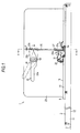
- Fig. 1 is a side view showing a vehicle seat sliding apparatus 1 according to the embodiment which is mounted on a vehicle such as an automotive vehicle
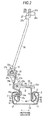
- Fig. 2 is a cross-sectional view taken along the line A-A in Fig. 1
- a lower rail 3 is fixed to a vehicle floor 2 in a state of extending in the fore-and-aft direction of the vehicle
- an upper rail 4 is mounted to the lower rail 3 so as to be movable relatively to the lower rail 3.
- the lower rail 3 includes a pair of side wall portions 11 extending upright from both ends thereof in terms of the widthwise direction and a bottom wall portion 12 connecting proximal ends (lower ends) of the side wall portions 11. Then, folded-back wall portions 13 which are formed to protruded inward in terms of the widthwise direction and then folded backward toward the proximal end sides of the side wall portions 11 are formed continuously from distal ends (upper ends) of the respective side wall portions 11.
- the Upper rail 4 includes a pair of side wall portions 14 extending in the vertical direction between the both folded-back wall portions 13 of the lower rail 3 and a lid wall portion 15 connecting proximal ends (upper ends) of the side wall portions 14.
- folded-back wall portions 16 which are formed to protrude outward in terms of the widthwise direction and then folded so as to be surrounded by the side wall portions 11 and the folded-back wall portions 13 are formed continuously from distal ends (lower ends) of the respective side wall portions 14.
- the lower rail 3 and the upper rail 4 each include a U-shaped rail cross section with opening sides butted against to each other, and are held so as not to be disconnected from each other in the vertical direction mainly by the engagement of the folded-back wall portions 13 and 16.
- the rail cross section formed by the lower rail 3 and the upper rail 4 assume so-called a box shape in a rectangular shape.
- the lower rail 3 defines an internal space S in cooperation with the upper rail 4.
- Retainers 18 adapted to hold pairs of rolling elements 17 arranged in the vertical direction are mounted between the respective folded-back wall portions 16 and the side wall portions 11 opposing thereto, and the upper rail 4 is supported so as to be slidable in the longitudinal direction (the fore-and-aft direction of the vehicle) with respect to the lower rail 3 in a state of rolling the rolling elements 17 with respect to the lower rail 3.
- the folded-back wall portion 13 on one side of the lower rail 3 in terms of the widthwise direction is formed with a plurality of lock holes 13a arranged crosswise at predetermined intervals over the substantially entire length of the longitudinal direction (the direction orthogonal to a paper plane) thereof.
- a through hole 4a formed by removing a corner formed by the lid wall portion 15 and the side wall portion 14 on one side is formed with a through hole 4a formed by removing a corner formed by the lid wall portion 15 and the side wall portion 14 on one side (left side in Fig.
- a lower portion of the side wall portion 14 concerned is formed with a plurality of insertion holes 14a arranged crosswise at the predetermined intervals within a range of the through hole 4a in terms of the longitudinal direction and, in addition, the folded-back wall portion 16 which continues from the side wall portion 14 concerned is formed with the same number of insertion holes 16a as the insertion holes 14a arranged crosswise at the predetermined intervals.
- the plurality of insertion holes 14a and 16a are arranged at positions which can align with the same number of lock holes 13a on the lower rail 3 adjacent to each other in terms of the longitudinal direction so as to oppose each other in the widthwise direction.
- a lock lever 21 formed of a plate member is rotatably connected to the upper rail 4 via a bracket (not shown) within the range of the through hole 4a in the longitudinal direction.
- the lock lever 21 includes a body portion 21a in a substantially L-shape in cross-section and a pair of supporting strips 21b bent upward from both ends of a lower portion of the body portion 21a in terms of the longitudinal direction (the direction orthogonal to the paper plane) of the upper rail 4.
- the lock lever 21 is supported by the both supporting strips 21b so as to be rotatable about an axis of rotation O1 extending in the longitudinal direction of the upper rail 4 outside the internal space S.
- the lock lever 21 is formed with locking claws 21c formed from the body portion 21a so as to enter the interior of the internal space S through the through hole 4a and folded back outward in terms of the widthwise direction by the same number as that of the insertion holes 14a or the like at the predetermined intervals.
- the respective locking claws 21c are arranged so as to be inserted into and pulled out from the insertion holes 14a and 16a in association with the rotation of the lock lever 21 about the axis of rotation 01.
- An upper portion of the body portion 21a is divided into in terms of the longitudinal direction of the upper rail 4, and a locking strip 21d bent outward in terms of the widthwise direction is formed on one side (inner side in the direction orthogonal to the paper plane) and an attachment 21e bent outward in terms of the widthwise direction from a distal end thereof in parallel to the supporting strip 21b is formed on the other side (near side in the direction orthogonal to the paper plane).
- a torsion wire 22 formed of one wire member is installed above the upper rail 4.
- the torsion wire 22 includes a shaft portion 22a extending in the longitudinal direction of the upper rail 4, and an end portion 22b bent from a distal end on one side of the shaft portion 22a (the inner side in the direction orthogonal to the paper plane) and locked by the upper rail 4 and, in addition, an end portion 22c bent obliquely upward from a distal end on the other side of the shaft portion 22a (the near side in the direction orthogonal to the paper plane) and locked in a state of being resiliently abutted against a lower surface of the locking strip 21d.
- the lock lever 21 is constantly urged in the direction of rotation on the side where the locking claws 21c is inserted into the insertion holes 14a and the like (clockwise direction in the drawing) by the single torsion wire 22.
- the center of torsion of the torsion wire 22 (the shaft portion 22a) is deviated from the axis of rotation 01.
- a supporting bracket 23 formed of a plate member extending upward from the lid wall portion 15 in a vertical wall shape is tightened to the lid wall portion 15 of the upper rail 4.
- the vehicle seat sliding apparatus 1 includes the supporting brackets 23 as well as the lower rails 3, the upper rails 4, and the lock levers 21 described above are provided in pair respectively in terms of the rail width direction (the direction orthogonal to the paper plane in Fig. 1 ), and the both supporting brackets 23 fixed to the upper rails 4 support a seat which forms a seating portion for an occupant.
- the both supporting brackets 23 are provided with a pipe-shaped connecting shaft 24 extending in the rail width direction and bridging therebetween supported rotatably about an axis of rotation 02.
- Operating levers 25 formed of a panel member are connected to distal ends of the connecting shaft 24 which penetrate through the respective supporting brackets 23 so as to rotate integrally therewith.
- the operating levers 25 each include an operating portion 25a extending toward one side of the radial direction of the connecting shaft 24 (the left side in Fig. 1 ), and a connecting portion 25b extending toward the other side of the radial direction (the right side in Fig. 1 ) to a position near right above the attachment 21e.
- a round-rod shaped connecting rod 26 is connected to the attachment 21e and the connecting portion 25b so as to extend therebetween.
- an end portion 26a on one side of the connecting rod 26 is bent in the longitudinal direction of the upper rail 4 and is inserted through and connected directly to the attachment 21e.
- an end portion 26b on the other side of the connecting rod 26 is bent in the widthwise direction (the direction in which the connecting shaft 24 extends) of the upper rail 4 and is inserted through and connected directly to the connecting portion 25b.
- a resin-made clip 27 as a covering member is mounted on the end portion 26a of the connecting rod 26. As shown in the perspective views in Figs.
- the clip 27 includes a cylindrical covering portion 27a in which the end portion 26a is press-fitted, and a hook-shaped holding portion 27b adapted to lock the connecting rod 26 in the vicinity of the end portion 26a. Therefore, the clip 27 prevents the end portion 26a from coming into direct contact with a connecting portion of the attachment 21e at the covering portion 27a and also prevents the same from being disconnected from the connecting rod 26 at the holding portion 27b. Likewise, the clip 27 is also mounted on the end portion 26b of the connecting rod 26.
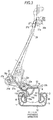
- the connecting rod 26 tilts by a very minute angle of inclination ⁇ in the longitudinal direction of the upper rail 4 about the attachment 21e (the end portion 26a) side (see Fig. 1 ). Also, the connecting rod 26 tilts by ah angle of inclination ⁇ in the rail width direction about the connecting portion 25b (end portion 26b) side (see Fig. 3 ). Accordingly, the each lock lever 21 is rotated counterclockwise about the axis of rotation O1, that is, in the direction of rotation in which the locking claws 21c are moved away from the insertion holes 14a or the like against an urging force of the torsion wire 22. Accordingly, the restriction of the relative movement between the lower rail 3 and the upper rail 4 is released.
- the clips 27 (covering portions 27a) mounted on both end portions 26a and 26b of the connecting rod 26 generate torsion in cooperation with the connecting rod 26 when pressing the connecting rod 26 in association with the rotation of the operating lever 25. Accordingly, an amount of deformation of the torsion of the connecting rod 26 is slightly restrained. Simultaneously, the clip 27 (the covering portion 27a) restrains rattling of the connecting rod 26 (the end portions 26a and 26b) at the attachment 21e or the connecting portion 25b.
- the center of the torsion of the torsion wire 22 (the shaft portion 22a) is deviated from the axis of rotation 01 of the lock lever 21. Therefore, as shown in Fig. 4 , the end portion 22c of the torsion wire 22 slides on the locking strip 21d in association with the rotation of the lock lever 21 about the axis of rotation 01.
- the supporting bracket 23 does not have to be provided upward from the upper rail 4 as long as it supports the seat.
- the number of locking claws 21c to be provided on the lock lever 21 may be any number as long as there is at least one.
- the cross-sectional shape of the lower rail 3 is shown simply as an example.
- the folded-back wall portions 13 may be protruded outward in terms of the rail widthwise direction.
- the cross-sectional shape of the upper rail 4 is shown simply as an example.
- the folded-back wall portions 16 may be protruded inward in terms of the rail widthwise direction.
- the rail cross section of the upper rail 4 is not limited to the U-shape, but may be an inverted T-shape.
- the direction of movement of the seat in association with the movement of upper rail 4 with respect to the lower rail 3 may be, for example, the fore-and-aft direction or the widthwise direction of the vehicle.
- the vehicle seat sliding apparatus wherein the axis of rotation of the lock lever extends in the longitudinal direction of the upper rail; and the axis of rotation of the operating lever extends in the widthwise direction of the upper rail.
- a vehicle seat sliding apparatus having a lower rail adapted to be fixed to a vehicle floor and an upper rail adapted to be fixed to a seat and connected to the lower rail so as to be movable with respect to the lower rail includes: a lock lever adapted to be connected rotatably to the upper rail and engaged with the lower rail for selectively restricting the movement of the upper rail with respect to the lower rail; an operating lever adapted to be connected rotatably to a supporting bracket adapted to support the seat in the direction of rotation different from the direction of rotation of the lock lever above the lock lever; and a'connecting rod adapted to be connected at one end and the other end directly to the lock lever and the operating lever respectively, and adapted to transmit an operating force to release restriction of the movement with respect to the lock lever by a pressing operation in association with the rotation of the operating lever.
Landscapes
- Engineering & Computer Science (AREA)
- Aviation & Aerospace Engineering (AREA)
- Transportation (AREA)
- Mechanical Engineering (AREA)
- Seats For Vehicles (AREA)
Abstract
Description
- The present invention relates to a vehicle seat sliding apparatus.
- In the related art, for example, a vehicle seat sliding apparatus as disclosed in
JP-A-2004-122825 Fig. 1 to Fig. 3 ) is known. This apparatus includes a lower rail (2), an upper rail (4) adapted to be connected to the lower rail so as to be movable with respect to the lower rail, and a lock lever (20) adapted to be connected rotatably to the upper rail via a bracket or the like and engaged with the lower rail for selectively restricting the movement of the upper rail with respect to the lower rail. When adjusting the position of a seat, an operating force applied to an operating lever (34) is transmitted to the lock lever via a first operating shaft (26) and a second operating shaft (28) to release the restriction of the movement by the lock lever. - In the vehicle seat sliding apparatus disclosed in
JP-A-2004-122825 - Thus, a need exists for a vehicle seat sliding apparatus which is not susceptible to the drawback mentioned above.
- In order to solve the drawback mentioned above, a first aspect of the invention provides a vehicle seat sliding apparatus having a lower rail adapted to be fixed to a vehicle floor and an upper rail adapted to be fixed to a seat and connected to the lower rail so as to be movable with respect to the lower rail, including: a lock lever adapted to be connected rotatably to the upper rail and engaged with the lower rail for selectively restricting the movement of the upper rail with respect to the lower rail; an operating lever adapted to be connected rotatably to a supporting bracket adapted to support the seat in the direction of rotation different from the direction of rotation of the lock lever above the lock lever; and a connecting rod adapted to be connected at one end and the other end directly to the lock lever and the operating lever respectively, and adapted to transmit an operating force to release restriction of the movement with respect to the lock lever by a pressing operation in association with the rotation of the operating lever.
- According to the configuration, the operating force for releasing the restriction of the relative movement can be transmitted to the lock lever in an extremely simple structure such as a pressing operation of the connecting rod in association with the rotation of the operating lever. Then, the transmission of the operating force between the operating lever and the lock lever can be achieved only by the single connecting rod, so that reduction in number of components is achieved.
- A second aspect of the invention is directed to the vehicle seat sliding apparatus of the first aspect, wherein a covering member adapted to restrain the amount of deformation of torsion of the connecting rod at the time of the pressing operation of the connecting rod in association with the rotation of the operating lever is mounted on at least one of the end portions of the connecting rod.
- According to the configuration, the amount of deformation of the torsion of the connecting rod can be restrained by the covering member, and hence a space required for installing the connecting rod can be reduced.
- A third aspect of the invention is directed to the vehicle seat sliding apparatus of the first or second aspect, which includes the lower rails, the upper rails, the lock levers, the operating levers, and connecting rods respectively in pairs, wherein the both operating levers are connected to a connecting shaft adapted to be bridged and supported therebetween so as to be rotate integrally therewith.
- According to the configuration, by the rotation of one of the pair of operating levers, the other one of the pair of operating levers can be rotated simultaneously via the connecting shaft synchronously, so that the operating force for releasing the restriction of movement can be transmitted simultaneously to the both of the pair of lock levers.
- According to the aspects of the invention, the vehicle seat sliding apparatus in which the operating force for releasing the restriction of movement of the upper rail with respect to the lower rail can be transmitted to the lock lever without increasing the number of components is provided.
-
-
Fig. 1 is a side view showing an embodiment of the invention; -
Fig. 2 is a cross-sectional view taken along the line A-A inFig. 1 ; -
Fig. 3 is a cross-sectional view showing an operation of the same embodiment; -
Fig. 4 is a cross-sectional view showing an operation of the same embodiment; -
Fig. 5A is a perspective view showing a connecting rod; and -
Fig. 5B is a perspective view showing the connecting rod. - Referring now to the drawings, an embodiment in which the invention is embodied will be described below.
-
Fig. 1 is a side view showing a vehicle seat sliding apparatus 1 according to the embodiment which is mounted on a vehicle such as an automotive vehicle, andFig. 2 is a cross-sectional view taken along the line A-A inFig. 1 . As shown inFig. 1 , alower rail 3 is fixed to a vehicle floor 2 in a state of extending in the fore-and-aft direction of the vehicle, and anupper rail 4 is mounted to thelower rail 3 so as to be movable relatively to thelower rail 3. - As shown in
Fig. 2 , thelower rail 3 includes a pair ofside wall portions 11 extending upright from both ends thereof in terms of the widthwise direction and abottom wall portion 12 connecting proximal ends (lower ends) of theside wall portions 11. Then, folded-back wall portions 13 which are formed to protruded inward in terms of the widthwise direction and then folded backward toward the proximal end sides of theside wall portions 11 are formed continuously from distal ends (upper ends) of the respectiveside wall portions 11. - In contrast, the
Upper rail 4 includes a pair ofside wall portions 14 extending in the vertical direction between the both folded-back wall portions 13 of thelower rail 3 and alid wall portion 15 connecting proximal ends (upper ends) of theside wall portions 14. Then, folded-back wall portions 16 which are formed to protrude outward in terms of the widthwise direction and then folded so as to be surrounded by theside wall portions 11 and the folded-back wall portions 13 are formed continuously from distal ends (lower ends) of the respectiveside wall portions 14. - In other words, the
lower rail 3 and theupper rail 4 each include a U-shaped rail cross section with opening sides butted against to each other, and are held so as not to be disconnected from each other in the vertical direction mainly by the engagement of the folded-back wall portions lower rail 3 and theupper rail 4 assume so-called a box shape in a rectangular shape. Thelower rail 3 defines an internal space S in cooperation with theupper rail 4. -
Retainers 18 adapted to hold pairs ofrolling elements 17 arranged in the vertical direction are mounted between the respective folded-back wall portions 16 and theside wall portions 11 opposing thereto, and theupper rail 4 is supported so as to be slidable in the longitudinal direction (the fore-and-aft direction of the vehicle) with respect to thelower rail 3 in a state of rolling therolling elements 17 with respect to thelower rail 3. - Here, the folded-
back wall portion 13 on one side of thelower rail 3 in terms of the widthwise direction (left side inFig. 2 ) is formed with a plurality oflock holes 13a arranged crosswise at predetermined intervals over the substantially entire length of the longitudinal direction (the direction orthogonal to a paper plane) thereof. In contrast, a throughhole 4a formed by removing a corner formed by thelid wall portion 15 and theside wall portion 14 on one side (left side inFig. 2 ) in terms of the widthwise direction is formed at a center portion of theupper rail 4 in terms of the longitudinal direction, and a lower portion of theside wall portion 14 concerned is formed with a plurality ofinsertion holes 14a arranged crosswise at the predetermined intervals within a range of the throughhole 4a in terms of the longitudinal direction and, in addition, the folded-back wall portion 16 which continues from theside wall portion 14 concerned is formed with the same number ofinsertion holes 16a as theinsertion holes 14a arranged crosswise at the predetermined intervals. The plurality ofinsertion holes lock holes 13a on thelower rail 3 adjacent to each other in terms of the longitudinal direction so as to oppose each other in the widthwise direction. - A
lock lever 21 formed of a plate member is rotatably connected to theupper rail 4 via a bracket (not shown) within the range of the throughhole 4a in the longitudinal direction. Thelock lever 21 includes abody portion 21a in a substantially L-shape in cross-section and a pair of supportingstrips 21b bent upward from both ends of a lower portion of thebody portion 21a in terms of the longitudinal direction (the direction orthogonal to the paper plane) of theupper rail 4. Thelock lever 21 is supported by the both supportingstrips 21b so as to be rotatable about an axis of rotation O1 extending in the longitudinal direction of theupper rail 4 outside the internal space S. Thelock lever 21 is formed withlocking claws 21c formed from thebody portion 21a so as to enter the interior of the internal space S through the throughhole 4a and folded back outward in terms of the widthwise direction by the same number as that of theinsertion holes 14a or the like at the predetermined intervals. Therespective locking claws 21c are arranged so as to be inserted into and pulled out from theinsertion holes lock lever 21 about the axis ofrotation 01. - When the
respective locking claws 21c are inserted into thelock holes 13a as well as into theinsertion holes lower rail 3 and theupper rail 4 is restricted. Alternatively, when therespective locking claws 21c are pulled out from theinsertion holes 16a, thelock holes 13a, and theinsertion holes 14a in sequence, the relative movement between thelower rail 3 and theupper rail 4 is allowed. - An upper portion of the
body portion 21a is divided into in terms of the longitudinal direction of theupper rail 4, and alocking strip 21d bent outward in terms of the widthwise direction is formed on one side (inner side in the direction orthogonal to the paper plane) and anattachment 21e bent outward in terms of the widthwise direction from a distal end thereof in parallel to the supportingstrip 21b is formed on the other side (near side in the direction orthogonal to the paper plane). Atorsion wire 22 formed of one wire member is installed above theupper rail 4. Thetorsion wire 22 includes ashaft portion 22a extending in the longitudinal direction of theupper rail 4, and anend portion 22b bent from a distal end on one side of theshaft portion 22a (the inner side in the direction orthogonal to the paper plane) and locked by theupper rail 4 and, in addition, anend portion 22c bent obliquely upward from a distal end on the other side of theshaft portion 22a (the near side in the direction orthogonal to the paper plane) and locked in a state of being resiliently abutted against a lower surface of thelocking strip 21d. Thelock lever 21 is constantly urged in the direction of rotation on the side where thelocking claws 21c is inserted into theinsertion holes 14a and the like (clockwise direction in the drawing) by thesingle torsion wire 22. The center of torsion of the torsion wire 22 (theshaft portion 22a) is deviated from the axis ofrotation 01. - As shown in
Fig. 1 , a supportingbracket 23 formed of a plate member extending upward from thelid wall portion 15 in a vertical wall shape is tightened to thelid wall portion 15 of theupper rail 4. The vehicle seat sliding apparatus 1 includes the supportingbrackets 23 as well as thelower rails 3, theupper rails 4, and thelock levers 21 described above are provided in pair respectively in terms of the rail width direction (the direction orthogonal to the paper plane inFig. 1 ), and the both supportingbrackets 23 fixed to theupper rails 4 support a seat which forms a seating portion for an occupant. Therefore, when the relative movement of theupper rails 4 with respect to thelower rails 3 is restricted by the engagement between thelocking claws 21c of the lock levers 21 and thelock holes 13a of thelower rails 3, the seat is held at a predetermined position with respect to the vehicle floor 2. Also, when the restriction of the relative movement is released by the release of the engagement between thelocking claws 21c of the lock levers 21 and thelock holes 13a of thelower rails 3, adjustment in position of the seat with respect to the vehicle floor 2 in the longitudinal direction of the upper rails 4 (the fore-and-aft direction of the vehicle) is allowed. - The both supporting
brackets 23 are provided with a pipe-shaped connectingshaft 24 extending in the rail width direction and bridging therebetween supported rotatably about an axis ofrotation 02.Operating levers 25 formed of a panel member are connected to distal ends of the connectingshaft 24 which penetrate through the respective supportingbrackets 23 so as to rotate integrally therewith. In other words, the direction of rotation of the operating lever 25 (the axis of rotation 02) is different from the direction of rotation of the lock lever 21 (axis of rotation O1). Theoperating levers 25 each include anoperating portion 25a extending toward one side of the radial direction of the connecting shaft 24 (the left side inFig. 1 ), and a connectingportion 25b extending toward the other side of the radial direction (the right side inFig. 1 ) to a position near right above theattachment 21e. - Then, a round-rod shaped connecting
rod 26 is connected to theattachment 21e and the connectingportion 25b so as to extend therebetween. In other words, anend portion 26a on one side of the connectingrod 26 is bent in the longitudinal direction of theupper rail 4 and is inserted through and connected directly to theattachment 21e. In contrast, anend portion 26b on the other side of the connectingrod 26 is bent in the widthwise direction (the direction in which the connectingshaft 24 extends) of theupper rail 4 and is inserted through and connected directly to the connectingportion 25b. A resin-madeclip 27 as a covering member is mounted on theend portion 26a of the connectingrod 26. As shown in the perspective views inFigs. 5A and 5B , theclip 27 includes acylindrical covering portion 27a in which theend portion 26a is press-fitted, and a hook-shapedholding portion 27b adapted to lock the connectingrod 26 in the vicinity of theend portion 26a. Therefore, theclip 27 prevents theend portion 26a from coming into direct contact with a connecting portion of theattachment 21e at the coveringportion 27a and also prevents the same from being disconnected from the connectingrod 26 at the holdingportion 27b. Likewise, theclip 27 is also mounted on theend portion 26b of the connectingrod 26. - In this configuration, it is assumed that the operating
portion 25a of the operatinglever 25 is operated, and the operating lever 25 (the connectingportion 25b) is rotated clockwise about the axis ofrotation 02 inFig. 1 . As described above, by the rotation of one of the pair of operating levers 25, theother operating lever 25 is rotated simultaneously via the connectingshaft 24. At this time, by the rotation of the connectingportion 25b so as to move downward, the connectingrod 26 presses thelock lever 21 directly in a state of causing theend portion 26a (and theattachment 21e) to be displaced outward in the rail width direction as shown inFig. 3 . In this case, the connectingrod 26 tilts by a very minute angle of inclination α in the longitudinal direction of theupper rail 4 about theattachment 21e (theend portion 26a) side (seeFig. 1 ). Also, the connectingrod 26 tilts by ah angle of inclination β in the rail width direction about the connectingportion 25b (end portion 26b) side (seeFig. 3 ). Accordingly, the eachlock lever 21 is rotated counterclockwise about the axis of rotation O1, that is, in the direction of rotation in which the lockingclaws 21c are moved away from theinsertion holes 14a or the like against an urging force of thetorsion wire 22. Accordingly, the restriction of the relative movement between thelower rail 3 and theupper rail 4 is released. The clips 27 (coveringportions 27a) mounted on bothend portions rod 26 generate torsion in cooperation with the connectingrod 26 when pressing the connectingrod 26 in association with the rotation of the operatinglever 25. Accordingly, an amount of deformation of the torsion of the connectingrod 26 is slightly restrained. Simultaneously, the clip 27 (the coveringportion 27a) restrains rattling of the connecting rod 26 (theend portions attachment 21e or the connectingportion 25b. - In this embodiment, the center of the torsion of the torsion wire 22 (the
shaft portion 22a) is deviated from the axis ofrotation 01 of thelock lever 21. Therefore, as shown inFig. 4 , theend portion 22c of thetorsion wire 22 slides on thelocking strip 21d in association with the rotation of thelock lever 21 about the axis ofrotation 01. In other words, when the distances from theshaft portion 22a to working points where theend portion 22c applies the urging force to thelocking strip 21d when thelock lever 21 is located respectively at a rotational position where the lockingclaws 21c and the lock holes 13a engage with each other and at a rotational position where the engagement is released from each other are expressed by the distances X, Y, a relationship "X ≠ Y" is established. In particular theend portion 22c is formed at a terminal end thereof so as to come into line contact with the lower surface of thelocking strip 21d when thelock lever 21 is located at the rotational position where the lockingclaws 21c and the lock holes 13a engage with each other. - As described above in detail, the following advantages are achieved according to this embodiment.
- (1) In this embodiment, an operating force for releasing the restriction of the relative movement between the
lower rail 3 and theupper rail 4 can be transmitted to thelock lever 21 in an extremely simple structure such as a pressing operation of the connectingrod 26 in association with the rotation of the operatinglever 25. Then, the transmission of the operating force between the operatinglever 25 and thelock lever 21 can be achieved only by the single connectingrod 26, so that reduction in number of components is achieved. Also, even though the direction of rotation of thelock lever 21 and the direction of rotation of the operatinglever 25 are different from each other, the operating lever 25 (the connectingportion 25b) is arranged above thelock lever 21. Then, the axis ofrotation 01 of thelock lever 21 extends in the longitudinal direction of theupper rail 4, and the axis ofrotation 02 of the operatinglever 25 extends in the widthwise direction of theupper rail 4. Therefore, at the time of the pressing operation of the connectingrod 26 in association with the rotation of the operatinglever 25, the angle of inclination α is restrained to a very minute angle and the connecting portion between the operatinglever 25 and the connectingrod 26 is prevented from being displaced in the longitudinal direction of theupper rail 4. - (2) In this embodiment, at the time of pressing operation of the connecting
rod 26 in association with the rotation of the operatinglever 25, the amount of deformation of the torsion of the connectingrod 26 can be restrained by theclips 27, and hence a space required for installing the connectingrod 26 can be reduced. - (3) In this embodiment, by the rotation of one of the pair of operating levers 25, the other one of the pair of operating levers 25 can be rotated simultaneously via the connecting
shaft 24 synchronously, so that the operating force for releasing the restriction of movement can be transmitted simultaneously to the both of the pair of lock levers 21, - The embodiment described above may be modified as follows.
- In the embodiment as described above, the supporting
bracket 23 does not have to be provided upward from theupper rail 4 as long as it supports the seat. - In the embodiment described above, the number of locking
claws 21c to be provided on thelock lever 21 may be any number as long as there is at least one. - In the embodiment described above, the cross-sectional shape of the
lower rail 3 is shown simply as an example. For example, the folded-back wall portions 13 may be protruded outward in terms of the rail widthwise direction. - In the embodiment described above, the cross-sectional shape of the
upper rail 4 is shown simply as an example. For example, the folded-back wall portions 16 may be protruded inward in terms of the rail widthwise direction. The rail cross section of theupper rail 4 is not limited to the U-shape, but may be an inverted T-shape. - The direction of movement of the seat in association with the movement of
upper rail 4 with respect to thelower rail 3 may be, for example, the fore-and-aft direction or the widthwise direction of the vehicle. - Subsequently, a technical idea understood from the embodiment and other examples described above will be added below.
- The vehicle seat sliding apparatus according to the invention,
wherein
the axis of rotation of the lock lever extends in the longitudinal direction of the upper rail; and
the axis of rotation of the operating lever extends in the widthwise direction of the upper rail. - A vehicle seat sliding apparatus having a lower rail adapted to be fixed to a vehicle floor and an upper rail adapted to be fixed to a seat and connected to the lower rail so as to be movable with respect to the lower rail includes: a lock lever adapted to be connected rotatably to the upper rail and engaged with the lower rail for selectively restricting the movement of the upper rail with respect to the lower rail; an operating lever adapted to be connected rotatably to a supporting bracket adapted to support the seat in the direction of rotation different from the direction of rotation of the lock lever above the lock lever; and a'connecting rod adapted to be connected at one end and the other end directly to the lock lever and the operating lever respectively, and adapted to transmit an operating force to release restriction of the movement with respect to the lock lever by a pressing operation in association with the rotation of the operating lever.
Claims (3)
- A vehicle seat sliding apparatus having a lower rail adapted to be fixed to a vehicle floor and an upper rail adapted to be fixed to a seat and connected to the lower rail so as to be movable with respect to the lower rail, comprising:a lock lever adapted to be connected rotatably to the upper rail and engaged with the lower rail for selectively restricting the movement of the upper rail with respect to the lower rail;an operating lever adapted to be connected rotatably to a supporting bracket adapted to support the seat in the direction of rotation different from the direction of rotation of the lock lever above the lock lever; anda connecting rod adapted to be connected at one end and the other end directly to the lock lever and the operating lever respectively, and adapted to transmit an operating force to release restriction of the movement with respect to the lock lever by a pressing operation in association with the rotation of the operating lever.
- The vehicle seat sliding apparatus according to Claim 1, wherein
a covering member adapted to restrain the amount of deformation of torsion of the connecting rod at the time of the pressing operation of the connecting rod in association with the rotation of the operating lever is mounted on at least one of the end portions of the connecting rod. - The vehicle seat sliding apparatus according to Claim 1 or 2, further comprising the lower rails, the upper rails, the lock levers, the operating levers, and connecting rods respectively in pairs, wherein
the both operating levers are connected to a connecting shaft adapted to be bridged and supported therebetween so as to be rotate integrally therewith.
Applications Claiming Priority (1)
| Application Number | Priority Date | Filing Date | Title |
|---|---|---|---|
| JP2008263015A JP5428275B2 (en) | 2008-10-09 | 2008-10-09 | Vehicle seat slide device |
Publications (3)
| Publication Number | Publication Date |
|---|---|
| EP2174829A2 true EP2174829A2 (en) | 2010-04-14 |
| EP2174829A3 EP2174829A3 (en) | 2010-11-03 |
| EP2174829B1 EP2174829B1 (en) | 2012-03-07 |
Family
ID=41667234
Family Applications (1)
| Application Number | Title | Priority Date | Filing Date |
|---|---|---|---|
| EP09171653A Not-in-force EP2174829B1 (en) | 2008-10-09 | 2009-09-29 | Vehicle seat sliding apparatus |
Country Status (5)
| Country | Link |
|---|---|
| US (1) | US8297582B2 (en) |
| EP (1) | EP2174829B1 (en) |
| JP (1) | JP5428275B2 (en) |
| CN (1) | CN101716894B (en) |
| AT (1) | ATE548215T1 (en) |
Families Citing this family (4)
| Publication number | Priority date | Publication date | Assignee | Title |
|---|---|---|---|---|
| JP5787368B2 (en) * | 2012-02-13 | 2015-09-30 | トヨタ車体株式会社 | Seat slide device |
| DE102019206304B4 (en) * | 2018-05-04 | 2022-01-27 | Lear Corporation | RAIL ARRANGEMENT |
| US11124091B2 (en) * | 2018-10-01 | 2021-09-21 | Ford Global Technologies, Llc | Seat release mechanism |
| FR3093035B1 (en) * | 2019-02-26 | 2021-03-19 | Faurecia Sieges Dautomobile | Manual release lever for seat slide |
Citations (1)
| Publication number | Priority date | Publication date | Assignee | Title |
|---|---|---|---|---|
| JP2004122825A (en) | 2002-09-30 | 2004-04-22 | Delta Kogyo Co Ltd | Locking mechanism of slide adjuster for vehicle |
Family Cites Families (16)
| Publication number | Priority date | Publication date | Assignee | Title |
|---|---|---|---|---|
| JP2570898Y2 (en) * | 1991-01-18 | 1998-05-13 | 三菱自動車工業株式会社 | Vehicle seat device |
| JP3655361B2 (en) * | 1995-08-09 | 2005-06-02 | シロキ工業株式会社 | Seat track |
| EP0943484A3 (en) * | 1998-03-17 | 2000-08-16 | Ohi Seisakusho Co., Ltd. | Seat slide unit |
| JP4120078B2 (en) * | 1998-12-25 | 2008-07-16 | アイシン精機株式会社 | Walk-in device for vehicle seat |
| US6585321B1 (en) * | 2000-11-28 | 2003-07-01 | Tachi-S Co., Ltd. | Seat adjuster for vehicle seat |
| JP4151366B2 (en) * | 2002-09-30 | 2008-09-17 | アイシン精機株式会社 | Walk-in device for vehicle seat |
| JP4103524B2 (en) * | 2002-09-30 | 2008-06-18 | アイシン精機株式会社 | Walk-in device for vehicle seat |
| JP4291662B2 (en) * | 2002-12-20 | 2009-07-08 | 富士機工株式会社 | Vehicle seat slide device |
| US6869057B2 (en) | 2002-12-20 | 2005-03-22 | Fuji Kiko Co., Ltd. | Seat slide device |
| JP2005007982A (en) * | 2003-06-18 | 2005-01-13 | Fuji Kiko Co Ltd | Seat slide unit for vehicle |
| JP4164045B2 (en) * | 2004-04-30 | 2008-10-08 | シロキ工業株式会社 | Seat reclining device |
| JP4872313B2 (en) * | 2005-11-04 | 2012-02-08 | アイシン精機株式会社 | Vehicle seat slide device |
| JP4939810B2 (en) * | 2006-01-27 | 2012-05-30 | 富士機工株式会社 | Vehicle seat slide device |
| JP2008074380A (en) * | 2006-08-25 | 2008-04-03 | Aisin Seiki Co Ltd | Seat slide device for vehicle |
| JP5098279B2 (en) * | 2006-10-04 | 2012-12-12 | アイシン精機株式会社 | Vehicle seat device |
| JP5287128B2 (en) * | 2008-10-15 | 2013-09-11 | アイシン精機株式会社 | Vehicle seat slide device |
-
2008
- 2008-10-09 JP JP2008263015A patent/JP5428275B2/en not_active Expired - Fee Related
-
2009
- 2009-09-28 CN CN2009101745237A patent/CN101716894B/en not_active Expired - Fee Related
- 2009-09-29 US US12/569,301 patent/US8297582B2/en active Active
- 2009-09-29 EP EP09171653A patent/EP2174829B1/en not_active Not-in-force
- 2009-09-29 AT AT09171653T patent/ATE548215T1/en active
Patent Citations (1)
| Publication number | Priority date | Publication date | Assignee | Title |
|---|---|---|---|---|
| JP2004122825A (en) | 2002-09-30 | 2004-04-22 | Delta Kogyo Co Ltd | Locking mechanism of slide adjuster for vehicle |
Also Published As
| Publication number | Publication date |
|---|---|
| US8297582B2 (en) | 2012-10-30 |
| CN101716894B (en) | 2013-07-10 |
| CN101716894A (en) | 2010-06-02 |
| JP5428275B2 (en) | 2014-02-26 |
| EP2174829B1 (en) | 2012-03-07 |
| US20100090081A1 (en) | 2010-04-15 |
| ATE548215T1 (en) | 2012-03-15 |
| JP2010089688A (en) | 2010-04-22 |
| EP2174829A3 (en) | 2010-11-03 |
Similar Documents
| Publication | Publication Date | Title |
|---|---|---|
| US8146878B2 (en) | Vehicle seat sliding apparatus | |
| EP2177393B1 (en) | Vehicle seat sliding apparatus | |
| JP5467602B2 (en) | Vehicle seat slide device | |
| EP2196354B1 (en) | Vehicle seat slide device | |
| JP5621444B2 (en) | Vehicle seat slide device | |
| EP2174829B1 (en) | Vehicle seat sliding apparatus | |
| JP5097790B2 (en) | Vehicle seat | |
| JPH08253062A (en) | Seat slide device for automobile | |
| EP2138347B1 (en) | Headrest and vehicle seat with the headrest | |
| JP2003146119A (en) | Seat slide device | |
| WO2017022530A1 (en) | Seat sliding device for vehicle | |
| JP2019116217A (en) | Vehicle seat slide device | |
| CN111332163A (en) | Seat slide device for vehicle | |
| US8052113B2 (en) | Seat slide apparatus for vehicle | |
| JP2006335104A (en) | Seat slide device of vehicle | |
| JP2007137291A (en) | Seat track device | |
| JP2005225262A (en) | Seat slide device | |
| EP0405552A2 (en) | Vehicle seat | |
| EP1470020B1 (en) | Automotive seat track having vertically adjustable bearings | |
| JP3964753B2 (en) | Airbag fixing part structure | |
| JP2000264132A (en) | Slide support device for console | |
| JP3600858B2 (en) | Mounting structure of slide rails for vehicle seats | |
| JP2019116219A (en) | Vehicle seat slide device | |
| JP2021160648A (en) | Vehicular seat slide device | |
| JP2544136Y2 (en) | Automotive seat slide device |
Legal Events
| Date | Code | Title | Description |
|---|---|---|---|
| PUAI | Public reference made under article 153(3) epc to a published international application that has entered the european phase |
Free format text: ORIGINAL CODE: 0009012 |
|
| AK | Designated contracting states |
Kind code of ref document: A2 Designated state(s): AT BE BG CH CY CZ DE DK EE ES FI FR GB GR HR HU IE IS IT LI LT LU LV MC MK MT NL NO PL PT RO SE SI SK SM TR |
|
| AX | Request for extension of the european patent |
Extension state: AL BA RS |
|
| PUAL | Search report despatched |
Free format text: ORIGINAL CODE: 0009013 |
|
| AK | Designated contracting states |
Kind code of ref document: A3 Designated state(s): AT BE BG CH CY CZ DE DK EE ES FI FR GB GR HR HU IE IS IT LI LT LU LV MC MK MT NL NO PL PT RO SE SI SK SM TR |
|
| AX | Request for extension of the european patent |
Extension state: AL BA RS |
|
| 17P | Request for examination filed |
Effective date: 20110503 |
|
| GRAP | Despatch of communication of intention to grant a patent |
Free format text: ORIGINAL CODE: EPIDOSNIGR1 |
|
| 17Q | First examination report despatched |
Effective date: 20110712 |
|
| GRAS | Grant fee paid |
Free format text: ORIGINAL CODE: EPIDOSNIGR3 |
|
| GRAA | (expected) grant |
Free format text: ORIGINAL CODE: 0009210 |
|
| AK | Designated contracting states |
Kind code of ref document: B1 Designated state(s): AT BE BG CH CY CZ DE DK EE ES FI FR GB GR HR HU IE IS IT LI LT LU LV MC MK MT NL NO PL PT RO SE SI SK SM TR |
|
| REG | Reference to a national code |
Ref country code: GB Ref legal event code: FG4D |
|
| REG | Reference to a national code |
Ref country code: AT Ref legal event code: REF Ref document number: 548215 Country of ref document: AT Kind code of ref document: T Effective date: 20120315 Ref country code: CH Ref legal event code: EP |
|
| REG | Reference to a national code |
Ref country code: IE Ref legal event code: FG4D |
|
| REG | Reference to a national code |
Ref country code: DE Ref legal event code: R096 Ref document number: 602009005739 Country of ref document: DE Effective date: 20120503 |
|
| REG | Reference to a national code |
Ref country code: NL Ref legal event code: VDEP Effective date: 20120307 |
|
| PG25 | Lapsed in a contracting state [announced via postgrant information from national office to epo] |
Ref country code: HR Free format text: LAPSE BECAUSE OF FAILURE TO SUBMIT A TRANSLATION OF THE DESCRIPTION OR TO PAY THE FEE WITHIN THE PRESCRIBED TIME-LIMIT Effective date: 20120307 Ref country code: NO Free format text: LAPSE BECAUSE OF FAILURE TO SUBMIT A TRANSLATION OF THE DESCRIPTION OR TO PAY THE FEE WITHIN THE PRESCRIBED TIME-LIMIT Effective date: 20120607 Ref country code: NL Free format text: LAPSE BECAUSE OF FAILURE TO SUBMIT A TRANSLATION OF THE DESCRIPTION OR TO PAY THE FEE WITHIN THE PRESCRIBED TIME-LIMIT Effective date: 20120307 Ref country code: LT Free format text: LAPSE BECAUSE OF FAILURE TO SUBMIT A TRANSLATION OF THE DESCRIPTION OR TO PAY THE FEE WITHIN THE PRESCRIBED TIME-LIMIT Effective date: 20120307 |
|
| LTIE | Lt: invalidation of european patent or patent extension |
Effective date: 20120307 |
|
| PG25 | Lapsed in a contracting state [announced via postgrant information from national office to epo] |
Ref country code: GR Free format text: LAPSE BECAUSE OF FAILURE TO SUBMIT A TRANSLATION OF THE DESCRIPTION OR TO PAY THE FEE WITHIN THE PRESCRIBED TIME-LIMIT Effective date: 20120608 Ref country code: LV Free format text: LAPSE BECAUSE OF FAILURE TO SUBMIT A TRANSLATION OF THE DESCRIPTION OR TO PAY THE FEE WITHIN THE PRESCRIBED TIME-LIMIT Effective date: 20120307 Ref country code: FI Free format text: LAPSE BECAUSE OF FAILURE TO SUBMIT A TRANSLATION OF THE DESCRIPTION OR TO PAY THE FEE WITHIN THE PRESCRIBED TIME-LIMIT Effective date: 20120307 |
|
| REG | Reference to a national code |
Ref country code: AT Ref legal event code: MK05 Ref document number: 548215 Country of ref document: AT Kind code of ref document: T Effective date: 20120307 |
|
| PG25 | Lapsed in a contracting state [announced via postgrant information from national office to epo] |
Ref country code: CY Free format text: LAPSE BECAUSE OF FAILURE TO SUBMIT A TRANSLATION OF THE DESCRIPTION OR TO PAY THE FEE WITHIN THE PRESCRIBED TIME-LIMIT Effective date: 20120307 |
|
| PG25 | Lapsed in a contracting state [announced via postgrant information from national office to epo] |
Ref country code: SE Free format text: LAPSE BECAUSE OF FAILURE TO SUBMIT A TRANSLATION OF THE DESCRIPTION OR TO PAY THE FEE WITHIN THE PRESCRIBED TIME-LIMIT Effective date: 20120307 Ref country code: IS Free format text: LAPSE BECAUSE OF FAILURE TO SUBMIT A TRANSLATION OF THE DESCRIPTION OR TO PAY THE FEE WITHIN THE PRESCRIBED TIME-LIMIT Effective date: 20120707 Ref country code: SI Free format text: LAPSE BECAUSE OF FAILURE TO SUBMIT A TRANSLATION OF THE DESCRIPTION OR TO PAY THE FEE WITHIN THE PRESCRIBED TIME-LIMIT Effective date: 20120307 Ref country code: EE Free format text: LAPSE BECAUSE OF FAILURE TO SUBMIT A TRANSLATION OF THE DESCRIPTION OR TO PAY THE FEE WITHIN THE PRESCRIBED TIME-LIMIT Effective date: 20120307 Ref country code: CZ Free format text: LAPSE BECAUSE OF FAILURE TO SUBMIT A TRANSLATION OF THE DESCRIPTION OR TO PAY THE FEE WITHIN THE PRESCRIBED TIME-LIMIT Effective date: 20120307 Ref country code: PL Free format text: LAPSE BECAUSE OF FAILURE TO SUBMIT A TRANSLATION OF THE DESCRIPTION OR TO PAY THE FEE WITHIN THE PRESCRIBED TIME-LIMIT Effective date: 20120307 Ref country code: BE Free format text: LAPSE BECAUSE OF FAILURE TO SUBMIT A TRANSLATION OF THE DESCRIPTION OR TO PAY THE FEE WITHIN THE PRESCRIBED TIME-LIMIT Effective date: 20120307 Ref country code: RO Free format text: LAPSE BECAUSE OF FAILURE TO SUBMIT A TRANSLATION OF THE DESCRIPTION OR TO PAY THE FEE WITHIN THE PRESCRIBED TIME-LIMIT Effective date: 20120307 |
|
| PG25 | Lapsed in a contracting state [announced via postgrant information from national office to epo] |
Ref country code: SK Free format text: LAPSE BECAUSE OF FAILURE TO SUBMIT A TRANSLATION OF THE DESCRIPTION OR TO PAY THE FEE WITHIN THE PRESCRIBED TIME-LIMIT Effective date: 20120307 Ref country code: PT Free format text: LAPSE BECAUSE OF FAILURE TO SUBMIT A TRANSLATION OF THE DESCRIPTION OR TO PAY THE FEE WITHIN THE PRESCRIBED TIME-LIMIT Effective date: 20120709 |
|
| PLBE | No opposition filed within time limit |
Free format text: ORIGINAL CODE: 0009261 |
|
| STAA | Information on the status of an ep patent application or granted ep patent |
Free format text: STATUS: NO OPPOSITION FILED WITHIN TIME LIMIT |
|
| PG25 | Lapsed in a contracting state [announced via postgrant information from national office to epo] |
Ref country code: AT Free format text: LAPSE BECAUSE OF FAILURE TO SUBMIT A TRANSLATION OF THE DESCRIPTION OR TO PAY THE FEE WITHIN THE PRESCRIBED TIME-LIMIT Effective date: 20120307 Ref country code: DK Free format text: LAPSE BECAUSE OF FAILURE TO SUBMIT A TRANSLATION OF THE DESCRIPTION OR TO PAY THE FEE WITHIN THE PRESCRIBED TIME-LIMIT Effective date: 20120307 |
|
| 26N | No opposition filed |
Effective date: 20121210 |
|
| PG25 | Lapsed in a contracting state [announced via postgrant information from national office to epo] |
Ref country code: IT Free format text: LAPSE BECAUSE OF FAILURE TO SUBMIT A TRANSLATION OF THE DESCRIPTION OR TO PAY THE FEE WITHIN THE PRESCRIBED TIME-LIMIT Effective date: 20120307 |
|
| REG | Reference to a national code |
Ref country code: DE Ref legal event code: R097 Ref document number: 602009005739 Country of ref document: DE Effective date: 20121210 |
|
| PG25 | Lapsed in a contracting state [announced via postgrant information from national office to epo] |
Ref country code: ES Free format text: LAPSE BECAUSE OF FAILURE TO SUBMIT A TRANSLATION OF THE DESCRIPTION OR TO PAY THE FEE WITHIN THE PRESCRIBED TIME-LIMIT Effective date: 20120618 Ref country code: MC Free format text: LAPSE BECAUSE OF NON-PAYMENT OF DUE FEES Effective date: 20120930 |
|
| REG | Reference to a national code |
Ref country code: IE Ref legal event code: MM4A |
|
| PG25 | Lapsed in a contracting state [announced via postgrant information from national office to epo] |
Ref country code: IE Free format text: LAPSE BECAUSE OF NON-PAYMENT OF DUE FEES Effective date: 20120929 Ref country code: BG Free format text: LAPSE BECAUSE OF FAILURE TO SUBMIT A TRANSLATION OF THE DESCRIPTION OR TO PAY THE FEE WITHIN THE PRESCRIBED TIME-LIMIT Effective date: 20120607 |
|
| PG25 | Lapsed in a contracting state [announced via postgrant information from national office to epo] |
Ref country code: MT Free format text: LAPSE BECAUSE OF FAILURE TO SUBMIT A TRANSLATION OF THE DESCRIPTION OR TO PAY THE FEE WITHIN THE PRESCRIBED TIME-LIMIT Effective date: 20120307 |
|
| PG25 | Lapsed in a contracting state [announced via postgrant information from national office to epo] |
Ref country code: TR Free format text: LAPSE BECAUSE OF FAILURE TO SUBMIT A TRANSLATION OF THE DESCRIPTION OR TO PAY THE FEE WITHIN THE PRESCRIBED TIME-LIMIT Effective date: 20120307 |
|
| REG | Reference to a national code |
Ref country code: CH Ref legal event code: PL |
|
| PG25 | Lapsed in a contracting state [announced via postgrant information from national office to epo] |
Ref country code: LU Free format text: LAPSE BECAUSE OF NON-PAYMENT OF DUE FEES Effective date: 20120929 Ref country code: SM Free format text: LAPSE BECAUSE OF FAILURE TO SUBMIT A TRANSLATION OF THE DESCRIPTION OR TO PAY THE FEE WITHIN THE PRESCRIBED TIME-LIMIT Effective date: 20120307 |
|
| PG25 | Lapsed in a contracting state [announced via postgrant information from national office to epo] |
Ref country code: LI Free format text: LAPSE BECAUSE OF NON-PAYMENT OF DUE FEES Effective date: 20130930 Ref country code: CH Free format text: LAPSE BECAUSE OF NON-PAYMENT OF DUE FEES Effective date: 20130930 Ref country code: HU Free format text: LAPSE BECAUSE OF FAILURE TO SUBMIT A TRANSLATION OF THE DESCRIPTION OR TO PAY THE FEE WITHIN THE PRESCRIBED TIME-LIMIT Effective date: 20090929 |
|
| PG25 | Lapsed in a contracting state [announced via postgrant information from national office to epo] |
Ref country code: MK Free format text: LAPSE BECAUSE OF FAILURE TO SUBMIT A TRANSLATION OF THE DESCRIPTION OR TO PAY THE FEE WITHIN THE PRESCRIBED TIME-LIMIT Effective date: 20120307 |
|
| REG | Reference to a national code |
Ref country code: FR Ref legal event code: PLFP Year of fee payment: 8 |
|
| REG | Reference to a national code |
Ref country code: FR Ref legal event code: PLFP Year of fee payment: 9 |
|
| REG | Reference to a national code |
Ref country code: DE Ref legal event code: R084 Ref document number: 602009005739 Country of ref document: DE |
|
| REG | Reference to a national code |
Ref country code: GB Ref legal event code: 746 Effective date: 20180112 |
|
| REG | Reference to a national code |
Ref country code: FR Ref legal event code: PLFP Year of fee payment: 10 |
|
| PGFP | Annual fee paid to national office [announced via postgrant information from national office to epo] |
Ref country code: DE Payment date: 20190917 Year of fee payment: 11 |
|
| PGFP | Annual fee paid to national office [announced via postgrant information from national office to epo] |
Ref country code: GB Payment date: 20190926 Year of fee payment: 11 |
|
| PGFP | Annual fee paid to national office [announced via postgrant information from national office to epo] |
Ref country code: FR Payment date: 20200812 Year of fee payment: 12 |
|
| REG | Reference to a national code |
Ref country code: DE Ref legal event code: R119 Ref document number: 602009005739 Country of ref document: DE |
|
| GBPC | Gb: european patent ceased through non-payment of renewal fee |
Effective date: 20200929 |
|
| PG25 | Lapsed in a contracting state [announced via postgrant information from national office to epo] |
Ref country code: DE Free format text: LAPSE BECAUSE OF NON-PAYMENT OF DUE FEES Effective date: 20210401 |
|
| PG25 | Lapsed in a contracting state [announced via postgrant information from national office to epo] |
Ref country code: GB Free format text: LAPSE BECAUSE OF NON-PAYMENT OF DUE FEES Effective date: 20200929 |
|
| PG25 | Lapsed in a contracting state [announced via postgrant information from national office to epo] |
Ref country code: FR Free format text: LAPSE BECAUSE OF NON-PAYMENT OF DUE FEES Effective date: 20210930 |