EP2174808A2 - Method of making a sealed duct from a cab post - Google Patents
Method of making a sealed duct from a cab post Download PDFInfo
- Publication number
- EP2174808A2 EP2174808A2 EP09171472A EP09171472A EP2174808A2 EP 2174808 A2 EP2174808 A2 EP 2174808A2 EP 09171472 A EP09171472 A EP 09171472A EP 09171472 A EP09171472 A EP 09171472A EP 2174808 A2 EP2174808 A2 EP 2174808A2
- Authority
- EP
- European Patent Office
- Prior art keywords
- post
- piece
- air vent
- foam
- clip member
- Prior art date
- Legal status (The legal status is an assumption and is not a legal conclusion. Google has not performed a legal analysis and makes no representation as to the accuracy of the status listed.)
- Granted
Links
Images


Classifications
-
- B—PERFORMING OPERATIONS; TRANSPORTING
- B60—VEHICLES IN GENERAL
- B60H—ARRANGEMENTS OF HEATING, COOLING, VENTILATING OR OTHER AIR-TREATING DEVICES SPECIALLY ADAPTED FOR PASSENGER OR GOODS SPACES OF VEHICLES
- B60H1/00—Heating, cooling or ventilating devices
- B60H1/00507—Details, e.g. mounting arrangements, desaeration devices
- B60H1/00557—Details of ducts or cables
- B60H1/00564—Details of ducts or cables of air ducts
-
- B—PERFORMING OPERATIONS; TRANSPORTING
- B60—VEHICLES IN GENERAL
- B60H—ARRANGEMENTS OF HEATING, COOLING, VENTILATING OR OTHER AIR-TREATING DEVICES SPECIALLY ADAPTED FOR PASSENGER OR GOODS SPACES OF VEHICLES
- B60H1/00—Heating, cooling or ventilating devices
- B60H1/00357—Air-conditioning arrangements specially adapted for particular vehicles
- B60H1/00378—Air-conditioning arrangements specially adapted for particular vehicles for tractor or load vehicle cabins
-
- B—PERFORMING OPERATIONS; TRANSPORTING
- B60—VEHICLES IN GENERAL
- B60H—ARRANGEMENTS OF HEATING, COOLING, VENTILATING OR OTHER AIR-TREATING DEVICES SPECIALLY ADAPTED FOR PASSENGER OR GOODS SPACES OF VEHICLES
- B60H1/00—Heating, cooling or ventilating devices
- B60H1/24—Ventilating devices where the heating or cooling is irrelevant
- B60H1/241—Ventilating devices where the heating or cooling is irrelevant characterised by the location of ventilation devices in the vehicle
- B60H1/243—Ventilating devices where the heating or cooling is irrelevant characterised by the location of ventilation devices in the vehicle located in the lateral area (e.g. doors, pillars)
-
- B—PERFORMING OPERATIONS; TRANSPORTING
- B62—LAND VEHICLES FOR TRAVELLING OTHERWISE THAN ON RAILS
- B62D—MOTOR VEHICLES; TRAILERS
- B62D29/00—Superstructures, understructures, or sub-units thereof, characterised by the material thereof
- B62D29/001—Superstructures, understructures, or sub-units thereof, characterised by the material thereof characterised by combining metal and synthetic material
- B62D29/002—Superstructures, understructures, or sub-units thereof, characterised by the material thereof characterised by combining metal and synthetic material a foamable synthetic material or metal being added in situ
-
- B—PERFORMING OPERATIONS; TRANSPORTING
- B60—VEHICLES IN GENERAL
- B60H—ARRANGEMENTS OF HEATING, COOLING, VENTILATING OR OTHER AIR-TREATING DEVICES SPECIALLY ADAPTED FOR PASSENGER OR GOODS SPACES OF VEHICLES
- B60H1/00—Heating, cooling or ventilating devices
- B60H1/00507—Details, e.g. mounting arrangements, desaeration devices
- B60H2001/00635—Air-tight sealing devices
Definitions
- the present invention relates to a method of making a sealed duct from a cab post.
- HVAC heating-ventilation-air conditioning
- ROPS roll-over protection system
- an object of this invention is to provide a method of making a sealed duct from a cab post.
- a hollow cab post has open ends and a vent opening in a side surface.
- a piece of unexpanded foam is assembled to a clip.
- the clip is inserted through the vent opening so that the unexpanded foam is held inside the post to one side of the vent opening.
- the cab frame, including the post assembly may be dunked in an e-coat tank, after which the paint drains out of the post and around the unexpanded foam.
- This assembly is then heated, such as in a e-coat oven.
- the foam expands until it sealingly engages the inner walls of the post. This seals one end of the post and forces conditioned air to flow out of the post, through the vent opening and into the interior of the cab.
- a vehicle cab frame 10 includes corner posts 12, 14, 16, and 18 fixed, such as by welding, to a base 20 and to an upper front member 22, an upper rear member 24, an upper left side member 26, and an upper right side member 28.
- These members 22, 24, 26, and 28 are hollow and are preferably strong enough to function as roll-over-protection (ROPS).
- the posts, such as post 14, include an aperture or air vent 15 in an inwardly facing side wall thereof. Initially, both the upper and lower ends of the posts 14 are open. The upper end will remain open so it can receive conditioned air from a roof mounted HVAC system (not shown).
- a clip member 30 includes an arm 32 which extends between a flat horizontal rectangular base 34 and an upper part 36.
- a tab 35 projects upwardly from the base 34.
- Upper part 36 includes a horizontal arm 37 and a gripping part 38 which is bent to form a downwardly opening slot.
- a seal insert assembly 40 includes the clip member 30 and a rectangular piece 42 of unexpanded foam mounted on the base 34.
- the foam is conventional foam such as has been used for many years in the auto industry to prevent road noise from getting into passenger compartments.
- Foam piece 42 includes a pair of apertures 43 and 44. Aperture 43 receives a lower part of arm 32. Tab 35 projects through aperture 44.
- the seal insert assembly 40 is inserted through vent 15 and into the interior of the post 14 so that the unexpanded foam piece 42 is held inside the post 14 spaced apart and below or to one side of the vent 15, and so that gripping part 38 grips and hangs on a lower edge of the vent 15.
- the entire cab frame 10, including the post assembly as shown in Figs. 4 and 5 may then be dunked in a paint or e-coat tank (not shown), after which paint drains out of the post 14 and around the unexpanded foam piece 42.
- the entire cab frame 10 is then heated, such as in a paint or e-coat oven (not shown).
- the foam piece 42 expands until the expanded foam 46 sealingly engages the inner walls of the post 14, as best seen in Fig. 6 . This seals the lower end of the post 14 and forces conditioned air to flow out of the post 14, through the vent 15 and into the interior of the cab.
- This method is reasonably simple. Yet, it eliminates the need for welding, avoids paint problems, and avoids the difficulty of trying to install already expanded foam into a tube in a manner which guarantees it won't fall out, completely plugs the tube.
Landscapes
- Engineering & Computer Science (AREA)
- Mechanical Engineering (AREA)
- Physics & Mathematics (AREA)
- Thermal Sciences (AREA)
- Architecture (AREA)
- Structural Engineering (AREA)
- Chemical & Material Sciences (AREA)
- Combustion & Propulsion (AREA)
- Transportation (AREA)
- Body Structure For Vehicles (AREA)
- Air-Conditioning For Vehicles (AREA)
Abstract
Description
- The present invention relates to a method of making a sealed duct from a cab post.
- Utility vehicles such as tractors have cabs which include heating-ventilation-air conditioning (HVAC) units in the cab roof. It is well known that roof HVAC systems do not condition the air at the floor very well unless a duct is included that runs down to the floor. Such ducts can interfere with visibility from the inside of the cab.
- Most utility vehicles have a roll-over protection system (ROPS) formed from hollow tubing. In some utility vehicles such hollow ROPS tubes have been used as air ducts, this has been done with very heavy tubes and welded plates on the bottom to force the air out of a hole where a vent louver is placed. This has the disadvantage of high cost and problems with holding paint when using an e-coat system.
- Accordingly, an object of this invention is to provide a method of making a sealed duct from a cab post.
- This and other objects are achieved by the present invention, wherein a hollow cab post has open ends and a vent opening in a side surface. A piece of unexpanded foam is assembled to a clip. The clip is inserted through the vent opening so that the unexpanded foam is held inside the post to one side of the vent opening. The cab frame, including the post assembly, may be dunked in an e-coat tank, after which the paint drains out of the post and around the unexpanded foam. This assembly is then heated, such as in a e-coat oven. The foam expands until it sealingly engages the inner walls of the post. This seals one end of the post and forces conditioned air to flow out of the post, through the vent opening and into the interior of the cab.
- For a complete understanding of the objects, techniques, and structure of the invention reference should be made to the following detailed description and accompanying drawings:
- Fig. 1
- is a perspective view of a vehicle post assembly,
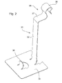
- Fig. 2
- is a perspective view of a clip member of the present invention,
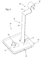
- Fig. 3
- is a perspective view of a seal insert assembly of the present invention,
- Fig. 4
- is an enlarged perspective view of the seal insert assembly mounted in a cab post,
- Fig. 5
- is an exterior perspective view of the seal insert assembly mounted in a cab post, and
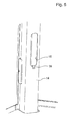
- Fig. 6
- is an enlarged perspective view of the seal insert assembly mounted in a cab post with an expanded foam piece.
- Referring to
Fig. 1 , avehicle cab frame 10 includescorner posts base 20 and to anupper front member 22, an upperrear member 24, an upperleft side member 26, and an upperright side member 28. Thesemembers post 14, include an aperture orair vent 15 in an inwardly facing side wall thereof. Initially, both the upper and lower ends of theposts 14 are open. The upper end will remain open so it can receive conditioned air from a roof mounted HVAC system (not shown). - Referring now to
Fig. 2 , aclip member 30 includes anarm 32 which extends between a flat horizontalrectangular base 34 and anupper part 36. Atab 35 projects upwardly from thebase 34.Upper part 36 includes ahorizontal arm 37 and agripping part 38 which is bent to form a downwardly opening slot. - Referring now to
Fig. 3 , aseal insert assembly 40 includes theclip member 30 and arectangular piece 42 of unexpanded foam mounted on thebase 34. Preferably, the foam is conventional foam such as has been used for many years in the auto industry to prevent road noise from getting into passenger compartments.Foam piece 42 includes a pair ofapertures Aperture 43 receives a lower part ofarm 32.Tab 35 projects throughaperture 44. - As best seen in
Figs. 4 and5 , theseal insert assembly 40 is inserted throughvent 15 and into the interior of thepost 14 so that theunexpanded foam piece 42 is held inside thepost 14 spaced apart and below or to one side of thevent 15, and so that grippingpart 38 grips and hangs on a lower edge of thevent 15. - The
entire cab frame 10, including the post assembly as shown inFigs. 4 and5 , may then be dunked in a paint or e-coat tank (not shown), after which paint drains out of thepost 14 and around theunexpanded foam piece 42. Theentire cab frame 10 is then heated, such as in a paint or e-coat oven (not shown). Thefoam piece 42 expands until the expandedfoam 46 sealingly engages the inner walls of thepost 14, as best seen inFig. 6 . This seals the lower end of thepost 14 and forces conditioned air to flow out of thepost 14, through thevent 15 and into the interior of the cab. - This method is reasonably simple. Yet, it eliminates the need for welding, avoids paint problems, and avoids the difficulty of trying to install already expanded foam into a tube in a manner which guarantees it won't fall out, completely plugs the tube.
- While the present invention has been described in conjunction with a specific embodiment, it is understood that many alternatives, modifications and variations will be apparent to those skilled in the art in light of the foregoing description. Accordingly, this invention is intended to embrace all such alternatives, modifications and variations which fall within the spirit and scope of the appended claims.
Claims (7)
- A method of making a sealed duct from a cab post, said method comprising:providing a hollow post (14), particularly being part of a vehicle cab frame (10), having a first end, a second end and an air vent (15) in a sidewall thereof; attaching a piece (42) of unexpanded foam to a clip member (30); inserting the clip member (30) together with the foam piece (42) through the air vent (15) and into the post (14) so that the unexpanded foam piece (42) is inside the post (14) and spaced apart from an edge of the air vent (15) and between the air vent (15) and the first end of the post (14); and heating the post (14) so that the foam piece (42) expands and forms a seal within the post (14) between the air vent (15) and the first end of the post (14).
- The method according to claim 1, characterized by providing the clip member (30) with a base (34), a gripping member (38) and an arm (32) connecting the base (34) to the gripping member (38), the base (34) supporting said piece (42) of unexpanded foam.
- The method according to claim 2, characterized by coupling the gripping member (38) to the post (14) so that the gripping member (38) grips said edge of the air vent (15).
- The method according to claim 2 or 3, characterized in that portions (32, 35) of the clip member (38) are received by a pair of apertures (43, 44) formed in the foam piece (42).
- The method according to one of claims 2 to 4, characterized by bending the gripping part (38) to form a downwardly opening slot.
- The method according to one of claims 1 to 5, characterized by forming an aperture (43, 44) in the piece (42) of unexpanded foam; and inserting a portion (32, 35) of the clip member (38) through said aperture (43, 44).
- The method according to one of claims 1 to 6, characterized by forming a pair of apertures (43, 44) in the piece (42) of unexpanded foam; and inserting portions (32, 35) of the clip member (30) through said apertures (43, 44), wherein each portion (32, 35) of the clip member (30) particularly extends upwardly through one of the apertures (43, 44).
Applications Claiming Priority (1)
| Application Number | Priority Date | Filing Date | Title |
|---|---|---|---|
| US12/248,524 US20100090361A1 (en) | 2008-10-09 | 2008-10-09 | Method of making a sealed duct from a cab post |
Publications (3)
| Publication Number | Publication Date |
|---|---|
| EP2174808A2 true EP2174808A2 (en) | 2010-04-14 |
| EP2174808A3 EP2174808A3 (en) | 2010-07-07 |
| EP2174808B1 EP2174808B1 (en) | 2011-08-10 |
Family
ID=41323557
Family Applications (1)
| Application Number | Title | Priority Date | Filing Date |
|---|---|---|---|
| EP09171472A Active EP2174808B1 (en) | 2008-10-09 | 2009-09-28 | Method of making a sealed duct from a cab post |
Country Status (5)
| Country | Link |
|---|---|
| US (1) | US20100090361A1 (en) |
| EP (1) | EP2174808B1 (en) |
| AT (1) | ATE519617T1 (en) |
| BR (1) | BRPI0904862A2 (en) |
| MX (1) | MX2009010892A (en) |
Cited By (2)
| Publication number | Priority date | Publication date | Assignee | Title |
|---|---|---|---|---|
| EP2423050A1 (en) * | 2010-08-26 | 2012-02-29 | Sika Technology AG | Fastening element and process to fasten an element to or in a part with a fastening element |
| EP3798031A1 (en) | 2019-09-24 | 2021-03-31 | CLAAS Tractor S.A.S. | Agricultural machine |
Families Citing this family (1)
| Publication number | Priority date | Publication date | Assignee | Title |
|---|---|---|---|---|
| US20150140917A9 (en) * | 2008-10-09 | 2015-05-21 | Paul Thomas Bruss | Sealed duct cab post |
Family Cites Families (11)
| Publication number | Priority date | Publication date | Assignee | Title |
|---|---|---|---|---|
| JPS6299206A (en) * | 1985-10-25 | 1987-05-08 | Toyota Motor Corp | Manufacture of air-conditioning duct for automobile |
| US5344208A (en) * | 1991-12-09 | 1994-09-06 | Chrysler Corporation | Reinforcement assembly for vehicle panels |
| US5506025A (en) * | 1995-01-09 | 1996-04-09 | Sika Corporation | Expandable baffle apparatus |
| US5642914A (en) * | 1995-03-24 | 1997-07-01 | Neo-Ex Lab. Inc. | Support structure for supporting foamable material on hollow structural member |
| US6146565A (en) * | 1998-07-15 | 2000-11-14 | Noble Polymers, L.L.C. | Method of forming a heat expandable acoustic baffle |
| US6347799B1 (en) * | 1999-04-01 | 2002-02-19 | Tyco Electronics Corporation | Cavity sealing article having improved sag resistance |
| FR2826621B1 (en) * | 2001-07-02 | 2003-09-26 | Hutchinson | SOUND INSULATION DEVICE FOR MOUNTING IN A TUBULAR PART, PARTICULARLY FOR AN AUTOMOTIVE BODY PART |
| US20040135058A1 (en) * | 2002-12-13 | 2004-07-15 | Joseph Wycech | Method and apparatus for inserting a structural reinforcing member within a portion of an article of manufacture |
| US7249415B2 (en) * | 2003-06-26 | 2007-07-31 | Zephyros, Inc. | Method of forming members for sealing or baffling |
| US6929312B2 (en) * | 2003-10-17 | 2005-08-16 | General Motors Corporation | Duct/frame element assemblages and methods of assembling ducts and frame elements |
| US7597382B2 (en) * | 2005-06-07 | 2009-10-06 | Zephyros, Inc. | Noise reduction member and system |
-
2008
- 2008-10-09 US US12/248,524 patent/US20100090361A1/en not_active Abandoned
-
2009
- 2009-09-28 EP EP09171472A patent/EP2174808B1/en active Active
- 2009-09-28 AT AT09171472T patent/ATE519617T1/en not_active IP Right Cessation
- 2009-10-07 BR BRPI0904862-6A patent/BRPI0904862A2/en not_active IP Right Cessation
- 2009-10-08 MX MX2009010892A patent/MX2009010892A/en active IP Right Grant
Cited By (2)
| Publication number | Priority date | Publication date | Assignee | Title |
|---|---|---|---|---|
| EP2423050A1 (en) * | 2010-08-26 | 2012-02-29 | Sika Technology AG | Fastening element and process to fasten an element to or in a part with a fastening element |
| EP3798031A1 (en) | 2019-09-24 | 2021-03-31 | CLAAS Tractor S.A.S. | Agricultural machine |
Also Published As
| Publication number | Publication date |
|---|---|
| ATE519617T1 (en) | 2011-08-15 |
| US20100090361A1 (en) | 2010-04-15 |
| EP2174808B1 (en) | 2011-08-10 |
| BRPI0904862A2 (en) | 2011-02-08 |
| MX2009010892A (en) | 2010-05-14 |
| EP2174808A3 (en) | 2010-07-07 |
Similar Documents
| Publication | Publication Date | Title |
|---|---|---|
| CN106167050B (en) | Front wall harden structure | |
| US20130244561A1 (en) | Sealed duct cab post | |
| US9446797B2 (en) | Front vehicle-body structure of vehicle | |
| CN105365528B (en) | For the air outlet fixed structure of vehicle | |
| EP2174808B1 (en) | Method of making a sealed duct from a cab post | |
| JP5324419B2 (en) | Body side structure | |
| US9573559B2 (en) | Front body structure of vehicle | |
| CN208036415U (en) | A kind of battery pack anticollision girder construction | |
| CN113165704A (en) | Open structural element for an instrument panel, associated cross-member and corresponding instrument panel | |
| JP4345980B2 (en) | Auto body front structure | |
| ES2354534T3 (en) | TRANSVERSAL SUPPORT FOR A MOTOR VEHICLE. | |
| JP2015085781A (en) | Outside air introduction device for vehicle | |
| JP5213801B2 (en) | Vehicle cabin equipment structure | |
| US12043089B2 (en) | Window vent | |
| JP6546470B2 (en) | Air conditioning duct connection structure | |
| KR100931215B1 (en) | Vehicle cross member structure | |
| JP2005067480A (en) | Mounting structure for plate members | |
| CN103909874A (en) | Vehicle interior structure | |
| KR101923880B1 (en) | Mounting structure of heating-duct for vehicle | |
| JP2014129097A (en) | Tractor cabin | |
| US20190031129A1 (en) | Radiator grille attachment | |
| JP2008068722A (en) | Front body structure of automobile | |
| JPH11189177A (en) | Cowl structure for automobile | |
| JP2008201349A (en) | Liquid tank mounting structure | |
| JP2010132175A (en) | Interior air discharge casing |
Legal Events
| Date | Code | Title | Description |
|---|---|---|---|
| PUAI | Public reference made under article 153(3) epc to a published international application that has entered the european phase |
Free format text: ORIGINAL CODE: 0009012 |
|
| AK | Designated contracting states |
Kind code of ref document: A2 Designated state(s): AT BE BG CH CY CZ DE DK EE ES FI FR GB GR HR HU IE IS IT LI LT LU LV MC MK MT NL NO PL PT RO SE SI SK SM TR |
|
| AX | Request for extension of the european patent |
Extension state: AL BA RS |
|
| PUAL | Search report despatched |
Free format text: ORIGINAL CODE: 0009013 |
|
| AK | Designated contracting states |
Kind code of ref document: A3 Designated state(s): AT BE BG CH CY CZ DE DK EE ES FI FR GB GR HR HU IE IS IT LI LT LU LV MC MK MT NL NO PL PT RO SE SI SK SM TR |
|
| AX | Request for extension of the european patent |
Extension state: AL BA RS |
|
| RIC1 | Information provided on ipc code assigned before grant |
Ipc: B60H 1/00 20060101AFI20091126BHEP Ipc: B62D 29/00 20060101ALI20100531BHEP |
|
| GRAP | Despatch of communication of intention to grant a patent |
Free format text: ORIGINAL CODE: EPIDOSNIGR1 |
|
| 17P | Request for examination filed |
Effective date: 20110107 |
|
| RIC1 | Information provided on ipc code assigned before grant |
Ipc: B60H 1/00 20060101AFI20110202BHEP Ipc: B62D 29/00 20060101ALI20110202BHEP |
|
| GRAS | Grant fee paid |
Free format text: ORIGINAL CODE: EPIDOSNIGR3 |
|
| GRAA | (expected) grant |
Free format text: ORIGINAL CODE: 0009210 |
|
| AK | Designated contracting states |
Kind code of ref document: B1 Designated state(s): AT BE BG CH CY CZ DE DK EE ES FI FR GB GR HR HU IE IS IT LI LT LU LV MC MK MT NL NO PL PT RO SE SI SK SM TR |
|
| REG | Reference to a national code |
Ref country code: GB Ref legal event code: FG4D |
|
| REG | Reference to a national code |
Ref country code: CH Ref legal event code: EP |
|
| REG | Reference to a national code |
Ref country code: IE Ref legal event code: FG4D |
|
| REG | Reference to a national code |
Ref country code: DE Ref legal event code: R096 Ref document number: 602009002066 Country of ref document: DE Effective date: 20111013 |
|
| REG | Reference to a national code |
Ref country code: NL Ref legal event code: VDEP Effective date: 20110810 |
|
| LTIE | Lt: invalidation of european patent or patent extension |
Effective date: 20110810 |
|
| PG25 | Lapsed in a contracting state [announced via postgrant information from national office to epo] |
Ref country code: IS Free format text: LAPSE BECAUSE OF FAILURE TO SUBMIT A TRANSLATION OF THE DESCRIPTION OR TO PAY THE FEE WITHIN THE PRESCRIBED TIME-LIMIT Effective date: 20111210 Ref country code: SE Free format text: LAPSE BECAUSE OF FAILURE TO SUBMIT A TRANSLATION OF THE DESCRIPTION OR TO PAY THE FEE WITHIN THE PRESCRIBED TIME-LIMIT Effective date: 20110810 Ref country code: FI Free format text: LAPSE BECAUSE OF FAILURE TO SUBMIT A TRANSLATION OF THE DESCRIPTION OR TO PAY THE FEE WITHIN THE PRESCRIBED TIME-LIMIT Effective date: 20110810 Ref country code: PT Free format text: LAPSE BECAUSE OF FAILURE TO SUBMIT A TRANSLATION OF THE DESCRIPTION OR TO PAY THE FEE WITHIN THE PRESCRIBED TIME-LIMIT Effective date: 20111212 Ref country code: NL Free format text: LAPSE BECAUSE OF FAILURE TO SUBMIT A TRANSLATION OF THE DESCRIPTION OR TO PAY THE FEE WITHIN THE PRESCRIBED TIME-LIMIT Effective date: 20110810 Ref country code: HR Free format text: LAPSE BECAUSE OF FAILURE TO SUBMIT A TRANSLATION OF THE DESCRIPTION OR TO PAY THE FEE WITHIN THE PRESCRIBED TIME-LIMIT Effective date: 20110810 Ref country code: NO Free format text: LAPSE BECAUSE OF FAILURE TO SUBMIT A TRANSLATION OF THE DESCRIPTION OR TO PAY THE FEE WITHIN THE PRESCRIBED TIME-LIMIT Effective date: 20111110 Ref country code: LT Free format text: LAPSE BECAUSE OF FAILURE TO SUBMIT A TRANSLATION OF THE DESCRIPTION OR TO PAY THE FEE WITHIN THE PRESCRIBED TIME-LIMIT Effective date: 20110810 |
|
| REG | Reference to a national code |
Ref country code: AT Ref legal event code: MK05 Ref document number: 519617 Country of ref document: AT Kind code of ref document: T Effective date: 20110810 |
|
| PG25 | Lapsed in a contracting state [announced via postgrant information from national office to epo] |
Ref country code: LV Free format text: LAPSE BECAUSE OF FAILURE TO SUBMIT A TRANSLATION OF THE DESCRIPTION OR TO PAY THE FEE WITHIN THE PRESCRIBED TIME-LIMIT Effective date: 20110810 Ref country code: SI Free format text: LAPSE BECAUSE OF FAILURE TO SUBMIT A TRANSLATION OF THE DESCRIPTION OR TO PAY THE FEE WITHIN THE PRESCRIBED TIME-LIMIT Effective date: 20110810 Ref country code: PL Free format text: LAPSE BECAUSE OF FAILURE TO SUBMIT A TRANSLATION OF THE DESCRIPTION OR TO PAY THE FEE WITHIN THE PRESCRIBED TIME-LIMIT Effective date: 20110810 Ref country code: AT Free format text: LAPSE BECAUSE OF FAILURE TO SUBMIT A TRANSLATION OF THE DESCRIPTION OR TO PAY THE FEE WITHIN THE PRESCRIBED TIME-LIMIT Effective date: 20110810 Ref country code: GR Free format text: LAPSE BECAUSE OF FAILURE TO SUBMIT A TRANSLATION OF THE DESCRIPTION OR TO PAY THE FEE WITHIN THE PRESCRIBED TIME-LIMIT Effective date: 20111111 Ref country code: CY Free format text: LAPSE BECAUSE OF FAILURE TO SUBMIT A TRANSLATION OF THE DESCRIPTION OR TO PAY THE FEE WITHIN THE PRESCRIBED TIME-LIMIT Effective date: 20110810 |
|
| PG25 | Lapsed in a contracting state [announced via postgrant information from national office to epo] |
Ref country code: BE Free format text: LAPSE BECAUSE OF FAILURE TO SUBMIT A TRANSLATION OF THE DESCRIPTION OR TO PAY THE FEE WITHIN THE PRESCRIBED TIME-LIMIT Effective date: 20110810 |
|
| PG25 | Lapsed in a contracting state [announced via postgrant information from national office to epo] |
Ref country code: SK Free format text: LAPSE BECAUSE OF FAILURE TO SUBMIT A TRANSLATION OF THE DESCRIPTION OR TO PAY THE FEE WITHIN THE PRESCRIBED TIME-LIMIT Effective date: 20110810 Ref country code: MC Free format text: LAPSE BECAUSE OF NON-PAYMENT OF DUE FEES Effective date: 20110930 Ref country code: CZ Free format text: LAPSE BECAUSE OF FAILURE TO SUBMIT A TRANSLATION OF THE DESCRIPTION OR TO PAY THE FEE WITHIN THE PRESCRIBED TIME-LIMIT Effective date: 20110810 |
|
| PG25 | Lapsed in a contracting state [announced via postgrant information from national office to epo] |
Ref country code: IT Free format text: LAPSE BECAUSE OF FAILURE TO SUBMIT A TRANSLATION OF THE DESCRIPTION OR TO PAY THE FEE WITHIN THE PRESCRIBED TIME-LIMIT Effective date: 20110810 Ref country code: RO Free format text: LAPSE BECAUSE OF FAILURE TO SUBMIT A TRANSLATION OF THE DESCRIPTION OR TO PAY THE FEE WITHIN THE PRESCRIBED TIME-LIMIT Effective date: 20110810 Ref country code: EE Free format text: LAPSE BECAUSE OF FAILURE TO SUBMIT A TRANSLATION OF THE DESCRIPTION OR TO PAY THE FEE WITHIN THE PRESCRIBED TIME-LIMIT Effective date: 20110810 |
|
| PLBE | No opposition filed within time limit |
Free format text: ORIGINAL CODE: 0009261 |
|
| STAA | Information on the status of an ep patent application or granted ep patent |
Free format text: STATUS: NO OPPOSITION FILED WITHIN TIME LIMIT |
|
| REG | Reference to a national code |
Ref country code: IE Ref legal event code: MM4A |
|
| PG25 | Lapsed in a contracting state [announced via postgrant information from national office to epo] |
Ref country code: DK Free format text: LAPSE BECAUSE OF FAILURE TO SUBMIT A TRANSLATION OF THE DESCRIPTION OR TO PAY THE FEE WITHIN THE PRESCRIBED TIME-LIMIT Effective date: 20110810 |
|
| 26N | No opposition filed |
Effective date: 20120511 |
|
| PG25 | Lapsed in a contracting state [announced via postgrant information from national office to epo] |
Ref country code: IE Free format text: LAPSE BECAUSE OF NON-PAYMENT OF DUE FEES Effective date: 20110928 |
|
| REG | Reference to a national code |
Ref country code: DE Ref legal event code: R097 Ref document number: 602009002066 Country of ref document: DE Effective date: 20120511 |
|
| PG25 | Lapsed in a contracting state [announced via postgrant information from national office to epo] |
Ref country code: MT Free format text: LAPSE BECAUSE OF FAILURE TO SUBMIT A TRANSLATION OF THE DESCRIPTION OR TO PAY THE FEE WITHIN THE PRESCRIBED TIME-LIMIT Effective date: 20110810 Ref country code: MK Free format text: LAPSE BECAUSE OF FAILURE TO SUBMIT A TRANSLATION OF THE DESCRIPTION OR TO PAY THE FEE WITHIN THE PRESCRIBED TIME-LIMIT Effective date: 20110810 |
|
| PG25 | Lapsed in a contracting state [announced via postgrant information from national office to epo] |
Ref country code: ES Free format text: LAPSE BECAUSE OF FAILURE TO SUBMIT A TRANSLATION OF THE DESCRIPTION OR TO PAY THE FEE WITHIN THE PRESCRIBED TIME-LIMIT Effective date: 20111121 Ref country code: SM Free format text: LAPSE BECAUSE OF FAILURE TO SUBMIT A TRANSLATION OF THE DESCRIPTION OR TO PAY THE FEE WITHIN THE PRESCRIBED TIME-LIMIT Effective date: 20110810 |
|
| PG25 | Lapsed in a contracting state [announced via postgrant information from national office to epo] |
Ref country code: LU Free format text: LAPSE BECAUSE OF NON-PAYMENT OF DUE FEES Effective date: 20110928 |
|
| PG25 | Lapsed in a contracting state [announced via postgrant information from national office to epo] |
Ref country code: BG Free format text: LAPSE BECAUSE OF FAILURE TO SUBMIT A TRANSLATION OF THE DESCRIPTION OR TO PAY THE FEE WITHIN THE PRESCRIBED TIME-LIMIT Effective date: 20111110 |
|
| PG25 | Lapsed in a contracting state [announced via postgrant information from national office to epo] |
Ref country code: TR Free format text: LAPSE BECAUSE OF FAILURE TO SUBMIT A TRANSLATION OF THE DESCRIPTION OR TO PAY THE FEE WITHIN THE PRESCRIBED TIME-LIMIT Effective date: 20110810 |
|
| PG25 | Lapsed in a contracting state [announced via postgrant information from national office to epo] |
Ref country code: HU Free format text: LAPSE BECAUSE OF FAILURE TO SUBMIT A TRANSLATION OF THE DESCRIPTION OR TO PAY THE FEE WITHIN THE PRESCRIBED TIME-LIMIT Effective date: 20110810 |
|
| REG | Reference to a national code |
Ref country code: CH Ref legal event code: PL |
|
| GBPC | Gb: european patent ceased through non-payment of renewal fee |
Effective date: 20130928 |
|
| PG25 | Lapsed in a contracting state [announced via postgrant information from national office to epo] |
Ref country code: GB Free format text: LAPSE BECAUSE OF NON-PAYMENT OF DUE FEES Effective date: 20130928 Ref country code: LI Free format text: LAPSE BECAUSE OF NON-PAYMENT OF DUE FEES Effective date: 20130930 Ref country code: CH Free format text: LAPSE BECAUSE OF NON-PAYMENT OF DUE FEES Effective date: 20130930 |
|
| REG | Reference to a national code |
Ref country code: FR Ref legal event code: PLFP Year of fee payment: 8 |
|
| PGFP | Annual fee paid to national office [announced via postgrant information from national office to epo] |
Ref country code: FR Payment date: 20160926 Year of fee payment: 8 |
|
| REG | Reference to a national code |
Ref country code: FR Ref legal event code: ST Effective date: 20180531 |
|
| PG25 | Lapsed in a contracting state [announced via postgrant information from national office to epo] |
Ref country code: FR Free format text: LAPSE BECAUSE OF NON-PAYMENT OF DUE FEES Effective date: 20171002 |
|
| PGFP | Annual fee paid to national office [announced via postgrant information from national office to epo] |
Ref country code: DE Payment date: 20250820 Year of fee payment: 17 |