EP2174167B1 - Marine electromagnetic survey cable and system - Google Patents
Marine electromagnetic survey cable and system Download PDFInfo
- Publication number
- EP2174167B1 EP2174167B1 EP08759315.8A EP08759315A EP2174167B1 EP 2174167 B1 EP2174167 B1 EP 2174167B1 EP 08759315 A EP08759315 A EP 08759315A EP 2174167 B1 EP2174167 B1 EP 2174167B1
- Authority
- EP
- European Patent Office
- Prior art keywords
- cable
- electrical
- coupled
- battery
- functionally
- Prior art date
- Legal status (The legal status is an assumption and is not a legal conclusion. Google has not performed a legal analysis and makes no representation as to the accuracy of the status listed.)
- Not-in-force
Links
Images

Classifications
-
- G—PHYSICS
- G01—MEASURING; TESTING
- G01V—GEOPHYSICS; GRAVITATIONAL MEASUREMENTS; DETECTING MASSES OR OBJECTS; TAGS
- G01V3/00—Electric or magnetic prospecting or detecting; Measuring magnetic field characteristics of the earth, e.g. declination, deviation
- G01V3/12—Electric or magnetic prospecting or detecting; Measuring magnetic field characteristics of the earth, e.g. declination, deviation operating with electromagnetic waves
-
- G—PHYSICS
- G01—MEASURING; TESTING
- G01V—GEOPHYSICS; GRAVITATIONAL MEASUREMENTS; DETECTING MASSES OR OBJECTS; TAGS
- G01V3/00—Electric or magnetic prospecting or detecting; Measuring magnetic field characteristics of the earth, e.g. declination, deviation
- G01V3/08—Electric or magnetic prospecting or detecting; Measuring magnetic field characteristics of the earth, e.g. declination, deviation operating with magnetic or electric fields produced or modified by objects or geological structures or by detecting devices
- G01V3/083—Controlled source electromagnetic [CSEM] surveying
Definitions
- the invention relates generally to the field of electromagnetic survey apparatus for subsurface exploration in the Earth. More particularly, the invention relates to structures for detector electrodes and arrays thereof for detection of electric fields resulting from electromagnetic fields imparted into the Earth.
- Electromagnetic surveying is used for, among other purposes, determining the presence of hydrocarbon bearing structures in the Earth's subsurface. Electromagnetic surveying includes what are called “controlled source” survey techniques. Controlled source electromagnetic surveying techniques include imparting an electric current or a magnetic field into the Earth, when such surveys are conducted on land, or imparting the same into sediments below the water bottom (sea floor) when such surveys are conducted in a marine environment. The techniques include measuring voltages and/or magnetic fields induced in electrodes, antennas and/or magnetometers disposed at the Earth's surface, in the water or on the sea floor. The voltages and/or magnetic fields are induced by interaction of the electromagnetic field caused by the electric current and/or magnetic field imparted into the Earth's subsurface (through the water bottom in marine surveys) with subsurface Earth formations.
- One type of marine controlled source electromagnetic surveying known in the art includes imparting alternating electric current into the sediments below the water bottom by applying current from a source, usually disposed on a survey vessel, to a dipole electrode towed by the survey vessel.
- a dipole electrode is typically an insulated electrical cable having two electrodes thereon at a selected spacing, sometimes 300 to 1000 meters or more.
- the alternating current has one or more selected frequencies, typically within a range of about 0.1 to 100 Hz.
- a plurality of detector electrodes is disposed on the water bottom at spaced apart locations, and the detector electrodes are connected to devices that record the voltages induced across various pairs of such electrodes.
- Such surveying is known as frequency domain controlled source electromagnetic surveying. Frequency domain EM survey techniques are described, for example in U.S. Patent No. 7,026,819 issued to Eidesmo et al.
- transient controlled source electromagnetic surveying Another technique for electromagnetic surveying of subsurface Earth formations known in the art is transient controlled source electromagnetic surveying.
- electric current is imparted into the Earth's subsurface using electrodes on a cable similar to those explained above as used for frequency domain surveying.
- the electric current may be direct current (DC).
- DC direct current
- the electric current is switched off, and induced voltages are measured, typically with respect to time over a selected time interval, using electrodes disposed on the water bottom as previously explained with reference to frequency domain surveying. Structure and composition of the Earth's subsurface are inferred by the time distribution of the induced voltages.
- Transient electromagnetic surveying techniques are described, for example, in U.S. Patent Application Publication No. 2006/0186887 filed by Strack et al.
- hydrocarbon bearing structures can be inferred because of resistivity contrast between hydrocarbon bearing structures, which can have electrical resistivities in a range of several ohm-meters to several hundred ohm-meters, and those of the adjacent, non hydrocarbon bearing Earth formations, which may have resistivities in a range of about 0.2 ohm-meters to several ohm-meters.
- WO-A-2005/006022 describes a geophysical sensor apparatus for use under water in the sea, comprising a plurality of seismic sensors for sensing seismic waves associated with underground formations, and a plurality of EM-sensors constituted preferably by electrodes for sensing electromagnetic waves associated with said underground formations.
- the geophysical sensor apparatus comprises a seismic receiver cable with a linear array of a plurality of seismic sensors and EM-sensors arranged inside a flexible outer skin, with said EM-sensors having electrodes on the outside of said outer skin.
- the cable is operated on the seafloor by a surface vessel, said vessel towing an electromagnetic transmitter antenna in addition to the seismic source.
- One aspect of the invention is a marine electromagnetic survey cable comprising:
- a marine electromagnetic survey system includes a sensor cable according to the first aspect disposed in a body of water; a recording device functionally coupled to one end of the sensor cable; and a source cable disposed in the body of water, the source cable including at least one antenna coupled to a source of electric current.
- FIG. 1 An example marine electromagnetic survey system is shown generally in FIG. 1 .
- the electromagnetic survey system includes a sensor cable 10 having thereon at spaced apart positions a plurality of sensor modules 12.
- the sensor modules 12 will be explained in more detail with reference to FIG. 2 and FIG. 3 .
- the sensor cable 10 is shown being towed by a survey vessel 18 moving on the surface of a body of water 22 such as a lake or the ocean. Towing the sensor cable 10 is only one possible implementation of a sensor cable. It is within the scope of the present invention for the sensor cable 10 to be deployed on the water bottom 23.
- the vessel 18 may include thereon equipment, shown generally at 20 and referred to for convenience as a "recording system” that may include devices (none shown separately) for navigation, energizing electrodes or antennas for imparting an electromagnetic field in the formations below the water bottom 23, and for recording and processing signals generated by the various sensor modules 12 on the sensor cable 10.
- a recording system may include devices (none shown separately) for navigation, energizing electrodes or antennas for imparting an electromagnetic field in the formations below the water bottom 23, and for recording and processing signals generated by the various sensor modules 12 on the sensor cable 10.
- the electromagnetic survey system shown in FIG. 1 includes electrodes 16 disposed at spaced apart positions along an electrically insulated source cable 14 that may be towed by the survey vessel 18 or by a different vessel (not shown).
- the source cable 14 alternatively may be deployed on the water bottom 23.
- the electrodes 16 may be energized at selected times by an electrical current source (not shown separately) in the recording system 20 or in other equipment (not shown) to induce an electromagnetic field in the formations below the water bottom 23.
- the configuration shown in FIG. 1 induces a horizontal dipole electric field in the subsurface when the electrodes 16 are energized by electric current. It is entirely within the scope of the present invention to induce vertical dipole electric fields in the subsurface, as well as to induce vertical and/or horizontal dipole magnetic fields in the subsurface.
- Inducing magnetic fields is typically performed by passing electrical current through a loop antenna or solenoid coil. Accordingly, the direction of and the type of field induced is not intended to limit the scope of the invention. Further, the invention is applicable to use with both frequency domain (continuous wave) and transient induced electromagnetic fields. See, for example, U.S. Patent Application Publication No. 2006/0186887 filed by Strack et al. for examples of all of the foregoing techniques for inducing an electromagnetic field in the subsurface.
- the sensor cable 10 may be made from helically wound, electrically conductive armor wires 10A, such as may be made from stainless steel or other high strength, corrosion resistant, electrically conductive material.
- the cable 10 may include one or more insulated electrical conductors and one or more optical fibers inside the armor wires 10A.
- Using an externally armored cable as shown in FIG. 2 may have the advantages of high axial strength of and high resistance to abrasion.
- the sensor cable 10 in the present example may be divided into segments, each of which terminates with a combination mechanical/electrical/optical connector 25 ("cable connector") coupled to the longitudinal ends of each cable segment.
- the cable connector 25 may be any type known in the art to make electrical and optical connection, and to transfer axial loading to a mating connector 27.
- mating connector 27 can be mounted in each longitudinal end of one of the sensor modules 12. The connectors 25, 27 resist entry of fluid under pressure when the connectors 25, 27 are coupled to each other.
- the sensor module housing 24 is preferably pressure resistant and defines a sealed interior chamber 26 therein.
- the housing 24 may be made from electrically non-conductive, high strength material such as glass fiber reinforced plastic, and should have a wall thickness selected to resist crushing at the maximum expected hydrostatic pressure expected to be exerted on the housing 24.
- the mating connectors 27 may be arranged in the longitudinal ends of the housing 24 as shown in FIG. 2 such that axial loading along the cable 10 is transferred through the housing 24 by the coupled cable connectors 25 and mating connectors 27.
- the sensor cable 10 may be assembled from a plurality of connector-terminated segments each coupled to a corresponding mating connector on a sensor module housing 24.
- the cable 10 may include armor wires 10A extending substantially continuously from end to end, and the sensor modules 12 may be affixed to the exterior of the armor wires 10A.
- a measuring electrode 28 may be disposed on the outer surface of the housing 24, and may be made, for example, from lead, gold, graphite or other corrosion resistant, electrically conductive, low electrode potential material. Electrical connection between the measuring electrode 28 and measuring circuits 34 (explained in more detail with reference to FIG. 3 ) disposed inside the chamber 26 in the housing 24 may be made through a pressure sealed, electrical feed through bulkhead 30 disposed through the wall of the housing 24 and exposed at one end to the interior of the chamber 26.
- One such feed through bulkhead is sold under model designation BMS by Kemlon Products, 1424 N. Main Street, Pearland, Texas 77581.
- the measuring circuits 34 may be powered by a battery 36 disposed inside the chamber 26 in the housing 24. Battery power may be preferable to supplying power from the recording system (20 in FIG. 1 ) over insulated electrical conductors in the sensor cable 10 so as to reduce the possibility of any electromagnetic fields resulting from current flowing along the cable 10 from interfering with the electromagnetic survey measurements made in the various sensor modules 12.
- the cable 10 may include one or more optical fibers 38 for conducting command signals, such as from the recording unit (20 in FIG. 1 ) to the circuits 34 in the various sensor modules 12, and for conducting signal telemetry from the modules 12 to the recording unit (20 in FIG. 1 ) or to a separate data storage device (not shown).
- An insulated electrical conductor 32 forming part of the cable (10 in FIG. 2 ) may pass through the chamber 26 in the housing 24 such that electrical continuity in such conductor 32 is maintained along substantially the entire length of the cable 10.
- Optical telemetry may be preferable to electrical telemetry for the same reason as using batteries for powering the circuits 34, namely, to reduce the incidence of electromagnetic fields caused by electrical current moving along the cable 10.
- the insulated electrical conductor 32 in the present example serves as a common potential reference between all of the sensor modules 12.
- the circuits 34 may include a resistor R electrically coupled between the measuring electrode (28 in FIG. 2 ) and the insulated conductor 32, which as explained above serves as a common reference.
- the resistor R is also electrically connected across the input terminals of a preamplifier 40.
- voltage drop across the resistor R resulting from voltage difference between a fixed potential reference (conductor 32) and the measuring electrode (28 in FIG. 2 ) will be input to the preamplifier 40.
- Such voltage drop will be related to magnitude of the electric field gradient existing where the electrode is located at any point in time.
- Output of the preamplifier 40 may be passed through filter 42, which may comprise an anti-aliasing, low pass filter or a filter for attenuating unwanted noise, before being digitized in an analog to digital converter (ADC) 44.
- ADC analog to digital converter
- the preamplifier 40 output may be directly digitized and the output of the ADC 44 can be digitally filtered.
- Output of the ADC 44, whether digitally filtered or not, may be conducted to an electrical to optical signal converter (EOC) 46.
- EOC 46 electrical to optical signal converter
- Output of the EOC 46 may be applied to the one or more optical fibers (38 in FIG. 2 ) in the cable (10 in FIG. 2 ) such that optical signals representative of the voltage measured by each measuring electrode (28 in FIG. 2 ) with respect to the reference conductor (32 in FIG. 2 ) may be communicated to the recording system (20 in FIG. 1 ) or to a data storage unit.
- the type of optical or other signal telemetry used in any implementation is
- the batteries 36 may be rechargeable to extend the usable deployment time that the cable (10 in FIG. 1 ) may have.
- the sensor modules 12 may each include a power conditioner 50 in operative connection with the battery 36.
- the power conditioner 50 may accept, for example, alternating current transmitter over a pair of insulated electrical conductors 52 disposed inside the armor 10A in the cable and convert it to suitable direct current to charge the battery 36 in each module 12.
- the electrical conductors 52 from each cable segment are coupled to the conductors in the subsequent cable segment by a relay K in each sensor module 12. Electrical power from the recording unit (20 in FIG. 1 ) may actuate the relay K in the sensor module 12 nearest the vessel along the cable.
- Using armored electrical cable having electrical conductors inside the armor will further reduce the possibility of such stray electromagnetic induction because the conductors will be shielded from the electromagnetic fields by the armor wires 10A.
- electrical power may be supplied to the conductors 52 during times when signals are not being acquired, so that the batteries 36 may be recharged for subsequent signal acquisition.
- a possible benefit of a sensor cable configured as explained herein is that a larger number of electric field amplitude measurements may be made along a given length of cable than may be possible using sensor cables known in the art prior to the present invention.
- Such prior art cables typically included a longitudinally spaced apart pair of electrodes for each electric field measurement. Such configuration necessarily increases the longitudinal distance between field measurement positions along the cable.
- Another possible benefit of a cable made according to the invention is that all the measurement electrodes are referenced to the same reference potential electrode. Variations in reference potential may be substantially eliminated.
Description
- The invention relates generally to the field of electromagnetic survey apparatus for subsurface exploration in the Earth. More particularly, the invention relates to structures for detector electrodes and arrays thereof for detection of electric fields resulting from electromagnetic fields imparted into the Earth.
- Electromagnetic surveying is used for, among other purposes, determining the presence of hydrocarbon bearing structures in the Earth's subsurface. Electromagnetic surveying includes what are called "controlled source" survey techniques. Controlled source electromagnetic surveying techniques include imparting an electric current or a magnetic field into the Earth, when such surveys are conducted on land, or imparting the same into sediments below the water bottom (sea floor) when such surveys are conducted in a marine environment. The techniques include measuring voltages and/or magnetic fields induced in electrodes, antennas and/or magnetometers disposed at the Earth's surface, in the water or on the sea floor. The voltages and/or magnetic fields are induced by interaction of the electromagnetic field caused by the electric current and/or magnetic field imparted into the Earth's subsurface (through the water bottom in marine surveys) with subsurface Earth formations.
- One type of marine controlled source electromagnetic surveying known in the art includes imparting alternating electric current into the sediments below the water bottom by applying current from a source, usually disposed on a survey vessel, to a dipole electrode towed by the survey vessel. A dipole electrode is typically an insulated electrical cable having two electrodes thereon at a selected spacing, sometimes 300 to 1000 meters or more. The alternating current has one or more selected frequencies, typically within a range of about 0.1 to 100 Hz. A plurality of detector electrodes is disposed on the water bottom at spaced apart locations, and the detector electrodes are connected to devices that record the voltages induced across various pairs of such electrodes. Such surveying is known as frequency domain controlled source electromagnetic surveying. Frequency domain EM survey techniques are described, for example in
U.S. Patent No. 7,026,819 issued to Eidesmo et al. - Another technique for electromagnetic surveying of subsurface Earth formations known in the art is transient controlled source electromagnetic surveying. In transient controlled source electromagnetic surveying, electric current is imparted into the Earth's subsurface using electrodes on a cable similar to those explained above as used for frequency domain surveying. The electric current may be direct current (DC). At a selected time or times, the electric current is switched off, and induced voltages are measured, typically with respect to time over a selected time interval, using electrodes disposed on the water bottom as previously explained with reference to frequency domain surveying. Structure and composition of the Earth's subsurface are inferred by the time distribution of the induced voltages. Transient electromagnetic surveying techniques are described, for example, in
U.S. Patent Application Publication No. 2006/0186887 filed by Strack et al. - Irrespective of the technique used, the presence of hydrocarbon bearing structures can be inferred because of resistivity contrast between hydrocarbon bearing structures, which can have electrical resistivities in a range of several ohm-meters to several hundred ohm-meters, and those of the adjacent, non hydrocarbon bearing Earth formations, which may have resistivities in a range of about 0.2 ohm-meters to several ohm-meters.
- There continues to be a need for improved techniques and apparatus for mapping the Earth's subsurface using electromagnetic measurements.
-
WO-A-2005/006022 describes a geophysical sensor apparatus for use under water in the sea, comprising a plurality of seismic sensors for sensing seismic waves associated with underground formations, and a plurality of EM-sensors constituted preferably by electrodes for sensing electromagnetic waves associated with said underground formations. In a preferred receiver cable configuration embodiment, the geophysical sensor apparatus comprises a seismic receiver cable with a linear array of a plurality of seismic sensors and EM-sensors arranged inside a flexible outer skin, with said EM-sensors having electrodes on the outside of said outer skin. The cable is operated on the seafloor by a surface vessel, said vessel towing an electromagnetic transmitter antenna in addition to the seismic source. - One aspect of the invention is a marine electromagnetic survey cable comprising:
- a reference electrode extending substantially along the entire length of the cable;
- at least one insulated electrical conductor;
- a plurality of spaced apart measuring electrodes disposed along the cable and electrically insulated from the reference electrode; and
- a plurality of voltage measuring circuits, each functionally coupled between a respective measuring electrode and the reference electrode,
- characterized in that the cable further comprises a battery associated with each measuring circuit to supply electrical power thereto, each battery electrically connected to the at least one electrical conductor, and a relay functionally associated with each battery,
- wherein each relay is configured to close electrical connection along the at least one electrical conductor when energized by a power source at one end of the cable and to break the electrical connection along the at least one electrical conductor when de-energized, such that each battery is charged when the corresponding functionally associated relay is energized.
- A marine electromagnetic survey system according to another aspect of the invention includes a sensor cable according to the first aspect disposed in a body of water;
a recording device functionally coupled to one end of the sensor cable; and
a source cable disposed in the body of water, the source cable including at least one antenna coupled to a source of electric current. - Other aspects and advantages of the invention will be apparent from the following description and the appended claims.
-
-
FIG. 1 shows one example of a cable-type electromagnetic survey system according to the invention. -
FIG. 2 shows more detail of one example of a sensor module in the cable system ofFIG. 1 . -
FIG. 3 shows more detail of example measurement and communication circuitry of the sensor module shown inFIG. 2 . -
FIG. 4 shows one example of a battery recharging system for the cable ofFIG. 1 . - An example marine electromagnetic survey system is shown generally in
FIG. 1 . The electromagnetic survey system includes asensor cable 10 having thereon at spaced apart positions a plurality ofsensor modules 12. Thesensor modules 12 will be explained in more detail with reference toFIG. 2 andFIG. 3 . Thesensor cable 10 is shown being towed by asurvey vessel 18 moving on the surface of a body ofwater 22 such as a lake or the ocean. Towing thesensor cable 10 is only one possible implementation of a sensor cable. It is within the scope of the present invention for thesensor cable 10 to be deployed on thewater bottom 23. - The
vessel 18 may include thereon equipment, shown generally at 20 and referred to for convenience as a "recording system" that may include devices (none shown separately) for navigation, energizing electrodes or antennas for imparting an electromagnetic field in the formations below thewater bottom 23, and for recording and processing signals generated by thevarious sensor modules 12 on thesensor cable 10. - The electromagnetic survey system shown in
FIG. 1 includeselectrodes 16 disposed at spaced apart positions along an electrically insulatedsource cable 14 that may be towed by thesurvey vessel 18 or by a different vessel (not shown). Thesource cable 14 alternatively may be deployed on thewater bottom 23. Theelectrodes 16 may be energized at selected times by an electrical current source (not shown separately) in therecording system 20 or in other equipment (not shown) to induce an electromagnetic field in the formations below thewater bottom 23. The configuration shown inFIG. 1 induces a horizontal dipole electric field in the subsurface when theelectrodes 16 are energized by electric current. It is entirely within the scope of the present invention to induce vertical dipole electric fields in the subsurface, as well as to induce vertical and/or horizontal dipole magnetic fields in the subsurface. Inducing magnetic fields is typically performed by passing electrical current through a loop antenna or solenoid coil. Accordingly, the direction of and the type of field induced is not intended to limit the scope of the invention. Further, the invention is applicable to use with both frequency domain (continuous wave) and transient induced electromagnetic fields. See, for example,U.S. Patent Application Publication No. 2006/0186887 filed by Strack et al. for examples of all of the foregoing techniques for inducing an electromagnetic field in the subsurface. - One example of a
sensor cable 10 and one of thesensor modules 12 is shown in more detail inFIG. 2 . Thesensor cable 10 may be made from helically wound, electricallyconductive armor wires 10A, such as may be made from stainless steel or other high strength, corrosion resistant, electrically conductive material. In one example, to be explained in more detail below thecable 10 may include one or more insulated electrical conductors and one or more optical fibers inside thearmor wires 10A. Using an externally armored cable as shown inFIG. 2 may have the advantages of high axial strength of and high resistance to abrasion. - The
sensor cable 10 in the present example may be divided into segments, each of which terminates with a combination mechanical/electrical/optical connector 25 ("cable connector") coupled to the longitudinal ends of each cable segment. Thecable connector 25 may be any type known in the art to make electrical and optical connection, and to transfer axial loading to amating connector 27. In the present examplesuch mating connector 27 can be mounted in each longitudinal end of one of thesensor modules 12. Theconnectors connectors - The
sensor module housing 24 is preferably pressure resistant and defines a sealedinterior chamber 26 therein. Thehousing 24 may be made from electrically non-conductive, high strength material such as glass fiber reinforced plastic, and should have a wall thickness selected to resist crushing at the maximum expected hydrostatic pressure expected to be exerted on thehousing 24. Themating connectors 27 may be arranged in the longitudinal ends of thehousing 24 as shown inFIG. 2 such that axial loading along thecable 10 is transferred through thehousing 24 by the coupledcable connectors 25 andmating connectors 27. Thus, thesensor cable 10 may be assembled from a plurality of connector-terminated segments each coupled to a corresponding mating connector on asensor module housing 24. Alternatively, thecable 10 may includearmor wires 10A extending substantially continuously from end to end, and thesensor modules 12 may be affixed to the exterior of thearmor wires 10A. - A measuring
electrode 28 may be disposed on the outer surface of thehousing 24, and may be made, for example, from lead, gold, graphite or other corrosion resistant, electrically conductive, low electrode potential material. Electrical connection between the measuringelectrode 28 and measuring circuits 34 (explained in more detail with reference toFIG. 3 ) disposed inside thechamber 26 in thehousing 24 may be made through a pressure sealed, electrical feed throughbulkhead 30 disposed through the wall of thehousing 24 and exposed at one end to the interior of thechamber 26. One such feed through bulkhead is sold under model designation BMS by Kemlon Products, 1424 N. Main Street, Pearland, Texas 77581. - The measuring
circuits 34 may be powered by abattery 36 disposed inside thechamber 26 in thehousing 24. Battery power may be preferable to supplying power from the recording system (20 inFIG. 1 ) over insulated electrical conductors in thesensor cable 10 so as to reduce the possibility of any electromagnetic fields resulting from current flowing along thecable 10 from interfering with the electromagnetic survey measurements made in thevarious sensor modules 12. - The
cable 10 may include one or moreoptical fibers 38 for conducting command signals, such as from the recording unit (20 inFIG. 1 ) to thecircuits 34 in thevarious sensor modules 12, and for conducting signal telemetry from themodules 12 to the recording unit (20 inFIG. 1 ) or to a separate data storage device (not shown). An insulatedelectrical conductor 32 forming part of the cable (10 inFIG. 2 ) may pass through thechamber 26 in thehousing 24 such that electrical continuity insuch conductor 32 is maintained along substantially the entire length of thecable 10. Optical telemetry may be preferable to electrical telemetry for the same reason as using batteries for powering thecircuits 34, namely, to reduce the incidence of electromagnetic fields caused by electrical current moving along thecable 10. The insulatedelectrical conductor 32 in the present example serves as a common potential reference between all of thesensor modules 12. - One example of the
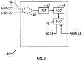
circuits 34 is shown in more detail inFIG. 3 . Thecircuits 34 may include a resistor R electrically coupled between the measuring electrode (28 inFIG. 2 ) and theinsulated conductor 32, which as explained above serves as a common reference. The resistor R is also electrically connected across the input terminals of apreamplifier 40. Thus, voltage drop across the resistor R resulting from voltage difference between a fixed potential reference (conductor 32) and the measuring electrode (28 inFIG. 2 ) will be input to thepreamplifier 40. Such voltage drop will be related to magnitude of the electric field gradient existing where the electrode is located at any point in time. - Output of the
preamplifier 40 may be passed throughfilter 42, which may comprise an anti-aliasing, low pass filter or a filter for attenuating unwanted noise, before being digitized in an analog to digital converter (ADC) 44. Alternatively, thepreamplifier 40 output may be directly digitized and the output of theADC 44 can be digitally filtered. Output of theADC 44, whether digitally filtered or not, may be conducted to an electrical to optical signal converter (EOC) 46. Output of theEOC 46 may be applied to the one or more optical fibers (38 inFIG. 2 ) in the cable (10 inFIG. 2 ) such that optical signals representative of the voltage measured by each measuring electrode (28 inFIG. 2 ) with respect to the reference conductor (32 inFIG. 2 ) may be communicated to the recording system (20 inFIG. 1 ) or to a data storage unit. The type of optical or other signal telemetry used in any implementation is a matter of discretion for the system designer and is not intended to limit the scope of the invention. - In some examples, the
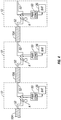
batteries 36 may be rechargeable to extend the usable deployment time that the cable (10 inFIG. 1 ) may have. Referring toFIG. 4 , in such examples, thesensor modules 12 may each include apower conditioner 50 in operative connection with thebattery 36. Thepower conditioner 50 may accept, for example, alternating current transmitter over a pair of insulatedelectrical conductors 52 disposed inside thearmor 10A in the cable and convert it to suitable direct current to charge thebattery 36 in eachmodule 12. In the example shown inFIG. 4 , theelectrical conductors 52 from each cable segment are coupled to the conductors in the subsequent cable segment by a relay K in eachsensor module 12. Electrical power from the recording unit (20 inFIG. 1 ) may actuate the relay K in thesensor module 12 nearest the vessel along the cable. When energized, such relay K will make connection to theelectrical conductors 52 coupled to the subsequent sensor module. Thus, electrical power will be supplied to all thepower conditioners 50 to charge all thebatteries 36. When the electrical power in theconductors 52 is switched off from the recording unit (20 inFIG. 1 ), however, theelectrical conductors 52 become electrically uncoupled from each other betweensuccessive sensor modules 12. Thus, there are no large, closed electrical conductor loops in thesensor cable 10 that may have stray voltages induced therein by the effects of the induced or other electromagnetic fields in the Earth's subsurface. Such stray voltages themselves would induce electromagnetic fields that could affect the measurements made by the electrodes (28 inFIG. 2 ) in the various sensor modules. Using armored electrical cable having electrical conductors inside the armor will further reduce the possibility of such stray electromagnetic induction because the conductors will be shielded from the electromagnetic fields by thearmor wires 10A. In using the system components shown inFIG. 4 , electrical power may be supplied to theconductors 52 during times when signals are not being acquired, so that thebatteries 36 may be recharged for subsequent signal acquisition. - A possible benefit of a sensor cable configured as explained herein is that a larger number of electric field amplitude measurements may be made along a given length of cable than may be possible using sensor cables known in the art prior to the present invention. Such prior art cables typically included a longitudinally spaced apart pair of electrodes for each electric field measurement. Such configuration necessarily increases the longitudinal distance between field measurement positions along the cable. Another possible benefit of a cable made according to the invention is that all the measurement electrodes are referenced to the same reference potential electrode. Variations in reference potential may be substantially eliminated.
- While the invention has been described with respect to a limited number of embodiments, those skilled in the art, having benefit of this disclosure, will appreciate that other embodiments can be devised which do not depart from the scope of the invention as disclosed herein. Accordingly, the scope of the invention should be limited only by the attached claims.
Claims (15)
- A marine electromagnetic survey cable (10), comprising:a reference electrode (32) extending substantially along the entire length of the cable;at least one insulated electrical conductor (52);a plurality of spaced apart measuring electrodes (28) disposed along the cable and electrically insulated from the reference electrode (32); anda plurality of voltage measuring circuits (34), each functionally coupled between a respective measuring electrode (28) and the reference electrode (32),characterized in that the cable further comprises:a battery (36) associated with each measuring circuit to supply electrical power thereto, each battery electrically connected to the at least one electrical conductor (52), and a relay (K) functionally associated with each battery (36),wherein each relay is configured to close electrical connection along the at least one electrical conductor when energized by a power source at one end of the cable and to break the electrical connection along the at least one electrical conductor when de-energized, such that each battery is charged when the corresponding functionally associated relay is energized.
- The cable of claim 1, further comprising a housing (24) associated with each measuring electrode (28), each housing formed from an electrically non-conductive material and defining a sealed chamber therein.
- The cable of claim 1 or claim 2, wherein each voltage measuring circuit (34) comprises a resistor (R) electrically coupled across the measuring electrode (28) and the reference electrode (32), and a preamplifier electrically coupled at its input across the resistor.
- The cable of claim 3, further comprising an electrical to optical converter (46) functionally coupled to an output of the preamplifier, an output of the electrical to optical converter coupled to an optical fiber associated with the cable.
- The cable of claim 4, wherein the cable comprises at least one optical fiber in signal communication with each electrical to optical converter.
- The cable of any of claims 1 to 5, further comprising a power conditioner functionally associated with each battery and each relay.
- The cable of any of the preceding claims, wherein the reference electrode (32) comprises armor wires.
- A marine electromagnetic survey system, comprising:a sensor cable according to claim 1 disposed in a body of water;a recording device (20) functionally coupled to one end of the sensor cable; anda source cable (14) disposed in the body of water, the source cable including at least one antenna coupled to a source of electric current.
- The system of claim 8, wherein the at least one antenna comprises a horizontal electric dipole.
- The system of claim 8 or claim 9, further comprising a housing (24) associated with each measuring electrode (28), each housing formed from an electrically non-conductive material and defining a sealed chamber therein.
- The system of any of claims 8 to 10, wherein each voltage measuring circuit (34) comprises a resistor (R) electrically coupled across the measuring electrode (28) and the reference electrode (32), and a preamplifier electrically coupled at its input across the resistor.
- The system of claim 11, further comprising an electrical to optical converter (46) functionally coupled to an output of the preamplifier, an output of the electrical to optical converter coupled to an optical fiber associated with the sensor cable.
- The system of any of claims 8 to 12, wherein the sensor cable comprises at least one optical fiber in signal communication with each electrical to optical converter.
- The system of any of claims 8 to 13, further comprising a power conditioner functionally associated with each battery and each relay.
- The system of any of claims 8 to 14 wherein the reference electrode (32) comprises armor wires.
Applications Claiming Priority (2)
| Application Number | Priority Date | Filing Date | Title |
|---|---|---|---|
| US11/823,940 US7602191B2 (en) | 2007-06-29 | 2007-06-29 | Cable-type electromagnetic receiver system for subsurface exploration |
| PCT/EP2008/005038 WO2009003604A2 (en) | 2007-06-29 | 2008-06-23 | Cable-type electromagnetic receiver system for subsurface exploration |
Publications (2)
| Publication Number | Publication Date |
|---|---|
| EP2174167A2 EP2174167A2 (en) | 2010-04-14 |
| EP2174167B1 true EP2174167B1 (en) | 2018-09-12 |
Family
ID=40159617
Family Applications (1)
| Application Number | Title | Priority Date | Filing Date |
|---|---|---|---|
| EP08759315.8A Not-in-force EP2174167B1 (en) | 2007-06-29 | 2008-06-23 | Marine electromagnetic survey cable and system |
Country Status (9)
| Country | Link |
|---|---|
| US (1) | US7602191B2 (en) |
| EP (1) | EP2174167B1 (en) |
| CN (1) | CN102124377B (en) |
| AU (1) | AU2008271640B2 (en) |
| CA (1) | CA2691422C (en) |
| EA (1) | EA016068B1 (en) |
| EG (1) | EG25386A (en) |
| MY (1) | MY150728A (en) |
| WO (1) | WO2009003604A2 (en) |
Families Citing this family (33)
| Publication number | Priority date | Publication date | Assignee | Title |
|---|---|---|---|---|
| US20100045296A1 (en) * | 2008-08-19 | 2010-02-25 | Pgs Geophysical As | Cable system for marine data acquisition |
| US8098542B2 (en) * | 2009-01-05 | 2012-01-17 | Pgs Geophysical As | Combined electromagnetic and seismic acquisition system and method |
| US8198899B2 (en) * | 2009-03-16 | 2012-06-12 | Pgs Geophysical As | Method and system for calibrating streamer electrodes in a marine electromagnetic survey system |
| BE1018801A3 (en) * | 2009-06-26 | 2011-09-06 | M D C E Bvba | METHOD AND DEVICE FOR DETERMINING A RHEOLOGICAL BORDER TRANSITION |
| US8179327B1 (en) * | 2009-09-25 | 2012-05-15 | The United States Of America, As Represented By The Secretary Of The Navy | Subsurface deployable antenna array |
| DE102010009104A1 (en) * | 2010-02-24 | 2011-08-25 | Epcos Ag, 81669 | detector circuit |
| US20110210741A1 (en) * | 2010-03-01 | 2011-09-01 | Suedow Gustav Goeran Mattias | Structure for magnetic field sensor for marine geophysical sensor streamer |
| US8319497B2 (en) | 2010-04-07 | 2012-11-27 | Pgs Geophysical As | Marine sensor streamer having pressure activated stiffness enhancement |
| US20110255368A1 (en) * | 2010-04-14 | 2011-10-20 | S Dow Gustav G Ran Mattias | Method for 2D and 3D electromagnetic field measurements using a towed marine electromagnetic survey system |
| US8575938B2 (en) * | 2010-04-20 | 2013-11-05 | Pgs Geophysical As | Electrical power system for towed electromagnetic survey streamers |
| US20110260730A1 (en) * | 2010-04-27 | 2011-10-27 | Suedow Gustav Goeran Mattias | Switchable front-end measurement unit for towed marine electromagnetic survey cables |
| US9778036B2 (en) * | 2010-04-27 | 2017-10-03 | Pgs Geophysical As | Switchable front-end measurement unit for towed marine electromagnetic streamer cables |
| US8896314B2 (en) | 2010-05-05 | 2014-11-25 | Pgs Geophysical As | Multiple component electromagnetic survey signal acquisition method |
| NO332630B1 (en) | 2010-09-13 | 2012-11-26 | Norges Geotekniske Inst | Marine field electric field sensor |
| US8797038B2 (en) | 2011-03-01 | 2014-08-05 | Pgs Geophysical As | High voltage DC power for electromagnetic survey source |
| US8514656B2 (en) | 2011-03-18 | 2013-08-20 | Pgs Geophysical As | Sensor arrangement for detecting motion induced noise in towed marine electromagnetic sensor streamers |
| US8710845B2 (en) | 2011-09-19 | 2014-04-29 | Pgs Geophysical As | Electromagnetic sensor cable and electrical configuration therefor |
| US9081106B2 (en) * | 2011-10-17 | 2015-07-14 | Pgs Geophysical As | Power converter and electrode combinations for electromagnetic survey source |
| CN102417039A (en) * | 2011-11-04 | 2012-04-18 | 哈尔滨飞机工业集团有限责任公司 | Receiving nacelle for time domain aircraft |
| US8816690B2 (en) | 2011-11-21 | 2014-08-26 | Pgs Geophysical As | Electromagnetic sensor cable and electrical configuration therefor |
| US8587316B2 (en) * | 2011-12-08 | 2013-11-19 | Pgs Geophysical As | Noise reduction systems and methods for a geophysical survey cable |
| US8736269B2 (en) | 2011-12-27 | 2014-05-27 | Pgs Geophysical As | Electromagnetic geophysical survey systems and methods employing electric potential mapping |
| AU2014265069B2 (en) * | 2011-12-27 | 2016-09-08 | Pgs Geophysical As | Electromagnetic geophysical survey systems and methods employing electric potential mapping |
| US8922214B2 (en) * | 2011-12-27 | 2014-12-30 | Pgs Geophysical As | Electromagnetic geophysical survey systems and methods employing electric potential mapping |
| US8928324B2 (en) | 2011-12-27 | 2015-01-06 | Pgs Geophysical As | In-line and broadside marine electromagnetic surveying |
| US8994378B2 (en) | 2012-05-09 | 2015-03-31 | Pgs Geophysical As | Acquisition system and method for towed electromagnetic sensor cable and source |
| US10175437B2 (en) * | 2014-02-18 | 2019-01-08 | Pgs Geophysical As | Subsea cable having floodable optical fiber conduit |
| GB201405977D0 (en) * | 2014-04-02 | 2014-05-14 | Univ Edinburgh | A receiver apparatus and method |
| US10605947B2 (en) * | 2014-06-18 | 2020-03-31 | Pgs Geophysical As | Marine streamer connector used as an electrode |
| US10012751B2 (en) | 2014-06-18 | 2018-07-03 | Pgs Geophysical As | Electrode adapter for geophysical surveys |
| US10042073B2 (en) * | 2014-10-17 | 2018-08-07 | Pgs Geophysical As | Electrically isolated streamer section |
| RU2639728C1 (en) * | 2016-06-30 | 2017-12-22 | Общество С Ограниченной Ответственностью "Сибирская Геофизическая Компания" | Data collection systems for maritime modification with coss and reception module |
| CN110231656B (en) | 2019-04-12 | 2020-04-07 | 清华大学 | Magnetic method detection device for unexplosive water area |
Family Cites Families (8)
| Publication number | Priority date | Publication date | Assignee | Title |
|---|---|---|---|---|
| FR2687228B1 (en) | 1992-02-12 | 1994-05-06 | Schlumberger Services Petroliers | DIAGRAPHY METHOD AND DEVICE FOR THE STUDY OF GEOMETRIC CHARACTERISTICS OF A WELL. |
| EP1306692B1 (en) | 1995-09-22 | 2006-03-15 | Input/Output, Inc. | Electric power distribution and communication system for an underwater cable |
| GB9818875D0 (en) * | 1998-08-28 | 1998-10-21 | Norske Stats Oljeselskap | Method and apparatus for determining the nature of subterranean reservoirs |
| NO326506B1 (en) | 2003-07-10 | 2008-12-15 | Norsk Hydro As | A marine geophysical collection system with a cable with seismic sources and receivers and electromagnetic sources and receivers |
| US7388380B2 (en) * | 2004-06-18 | 2008-06-17 | Schlumberger Technology | While-drilling apparatus for measuring streaming potentials and determining earth formation characteristics and other useful information |
| GB2423370B (en) * | 2005-02-22 | 2007-05-02 | Ohm Ltd | Electromagnetic surveying for resistive or conductive bodies |
| US20060186887A1 (en) * | 2005-02-22 | 2006-08-24 | Strack Kurt M | Method for identifying subsurface features from marine transient controlled source electromagnetic surveys |
| US7660192B2 (en) * | 2005-05-12 | 2010-02-09 | Western Geco L.L.C. | Seismic streamer receiver selection systems and methods |
-
2007
- 2007-06-29 US US11/823,940 patent/US7602191B2/en active Active
-
2008
- 2008-06-23 EA EA201070075A patent/EA016068B1/en not_active IP Right Cessation
- 2008-06-23 MY MYPI20095595 patent/MY150728A/en unknown
- 2008-06-23 WO PCT/EP2008/005038 patent/WO2009003604A2/en active Application Filing
- 2008-06-23 CN CN2008800225775A patent/CN102124377B/en not_active Expired - Fee Related
- 2008-06-23 CA CA2691422A patent/CA2691422C/en not_active Expired - Fee Related
- 2008-06-23 AU AU2008271640A patent/AU2008271640B2/en not_active Ceased
- 2008-06-23 EP EP08759315.8A patent/EP2174167B1/en not_active Not-in-force
-
2009
- 2009-12-23 EG EG2009121883A patent/EG25386A/en active
Non-Patent Citations (1)
| Title |
|---|
| None * |
Also Published As
| Publication number | Publication date |
|---|---|
| EA016068B1 (en) | 2012-01-30 |
| WO2009003604A2 (en) | 2009-01-08 |
| EG25386A (en) | 2011-12-25 |
| CN102124377A (en) | 2011-07-13 |
| US7602191B2 (en) | 2009-10-13 |
| CA2691422A1 (en) | 2009-01-08 |
| EA201070075A1 (en) | 2010-06-30 |
| BRPI0812752A2 (en) | 2020-08-18 |
| MY150728A (en) | 2014-02-28 |
| AU2008271640A1 (en) | 2009-01-08 |
| US20090001987A1 (en) | 2009-01-01 |
| AU2008271640B2 (en) | 2013-05-02 |
| CN102124377B (en) | 2013-08-21 |
| EP2174167A2 (en) | 2010-04-14 |
| WO2009003604A3 (en) | 2009-05-28 |
| CA2691422C (en) | 2013-10-15 |
Similar Documents
| Publication | Publication Date | Title |
|---|---|---|
| EP2174167B1 (en) | Marine electromagnetic survey cable and system | |
| US8198899B2 (en) | Method and system for calibrating streamer electrodes in a marine electromagnetic survey system | |
| AU2011201226B2 (en) | Method for 2D and 3D electromagnetic field measurements using a towed marine electromagnetic survey system | |
| US7737698B2 (en) | Low noise, towed electromagnetic system for subsurface exploration | |
| US20110260730A1 (en) | Switchable front-end measurement unit for towed marine electromagnetic survey cables | |
| US8098542B2 (en) | Combined electromagnetic and seismic acquisition system and method | |
| US8816690B2 (en) | Electromagnetic sensor cable and electrical configuration therefor | |
| US20150035537A1 (en) | Acquisition system and method for towed electromagnetic sensor cable and source | |
| US9778036B2 (en) | Switchable front-end measurement unit for towed marine electromagnetic streamer cables | |
| US10042073B2 (en) | Electrically isolated streamer section | |
| WO2012036559A1 (en) | E-field sensor for marine streaming | |
| BRPI0812752B1 (en) | MARINE ELECTROMAGNETIC LIFTING SYSTEM |
Legal Events
| Date | Code | Title | Description |
|---|---|---|---|
| PUAI | Public reference made under article 153(3) epc to a published international application that has entered the european phase |
Free format text: ORIGINAL CODE: 0009012 |
|
| 17P | Request for examination filed |
Effective date: 20100129 |
|
| AK | Designated contracting states |
Kind code of ref document: A2 Designated state(s): AT BE BG CH CY CZ DE DK EE ES FI FR GB GR HR HU IE IS IT LI LT LU LV MC MT NL NO PL PT RO SE SI SK TR |
|
| REG | Reference to a national code |
Ref country code: NO Ref legal event code: T1 |
|
| REG | Reference to a national code |
Ref country code: NO Ref legal event code: T1 |
|
| DAX | Request for extension of the european patent (deleted) | ||
| RAP1 | Party data changed (applicant data changed or rights of an application transferred) |
Owner name: PGS GEOPHYSICAL AS |
|
| STAA | Information on the status of an ep patent application or granted ep patent |
Free format text: STATUS: EXAMINATION IS IN PROGRESS |
|
| 17Q | First examination report despatched |
Effective date: 20170102 |
|
| GRAP | Despatch of communication of intention to grant a patent |
Free format text: ORIGINAL CODE: EPIDOSNIGR1 |
|
| STAA | Information on the status of an ep patent application or granted ep patent |
Free format text: STATUS: GRANT OF PATENT IS INTENDED |
|
| RIC1 | Information provided on ipc code assigned before grant |
Ipc: G01V 3/08 20060101ALI20180306BHEP Ipc: G01V 3/12 20060101AFI20180306BHEP |
|
| INTG | Intention to grant announced |
Effective date: 20180403 |
|
| GRAS | Grant fee paid |
Free format text: ORIGINAL CODE: EPIDOSNIGR3 |
|
| GRAA | (expected) grant |
Free format text: ORIGINAL CODE: 0009210 |
|
| STAA | Information on the status of an ep patent application or granted ep patent |
Free format text: STATUS: THE PATENT HAS BEEN GRANTED |
|
| AK | Designated contracting states |
Kind code of ref document: B1 Designated state(s): AT BE BG CH CY CZ DE DK EE ES FI FR GB GR HR HU IE IS IT LI LT LU LV MC MT NL NO PL PT RO SE SI SK TR |
|
| REG | Reference to a national code |
Ref country code: GB Ref legal event code: FG4D |
|
| REG | Reference to a national code |
Ref country code: CH Ref legal event code: EP |
|
| REG | Reference to a national code |
Ref country code: IE Ref legal event code: FG4D |
|
| REG | Reference to a national code |
Ref country code: DE Ref legal event code: R096 Ref document number: 602008056949 Country of ref document: DE |
|
| REG | Reference to a national code |
Ref country code: AT Ref legal event code: REF Ref document number: 1041286 Country of ref document: AT Kind code of ref document: T Effective date: 20181015 |
|
| REG | Reference to a national code |
Ref country code: NO Ref legal event code: T2 Effective date: 20180912 |
|
| REG | Reference to a national code |
Ref country code: NL Ref legal event code: MP Effective date: 20180912 |
|
| REG | Reference to a national code |
Ref country code: LT Ref legal event code: MG4D |
|
| PG25 | Lapsed in a contracting state [announced via postgrant information from national office to epo] |
Ref country code: FI Free format text: LAPSE BECAUSE OF FAILURE TO SUBMIT A TRANSLATION OF THE DESCRIPTION OR TO PAY THE FEE WITHIN THE PRESCRIBED TIME-LIMIT Effective date: 20180912 Ref country code: GR Free format text: LAPSE BECAUSE OF FAILURE TO SUBMIT A TRANSLATION OF THE DESCRIPTION OR TO PAY THE FEE WITHIN THE PRESCRIBED TIME-LIMIT Effective date: 20181213 Ref country code: SE Free format text: LAPSE BECAUSE OF FAILURE TO SUBMIT A TRANSLATION OF THE DESCRIPTION OR TO PAY THE FEE WITHIN THE PRESCRIBED TIME-LIMIT Effective date: 20180912 Ref country code: LT Free format text: LAPSE BECAUSE OF FAILURE TO SUBMIT A TRANSLATION OF THE DESCRIPTION OR TO PAY THE FEE WITHIN THE PRESCRIBED TIME-LIMIT Effective date: 20180912 Ref country code: BG Free format text: LAPSE BECAUSE OF FAILURE TO SUBMIT A TRANSLATION OF THE DESCRIPTION OR TO PAY THE FEE WITHIN THE PRESCRIBED TIME-LIMIT Effective date: 20181212 |
|
| PG25 | Lapsed in a contracting state [announced via postgrant information from national office to epo] |
Ref country code: ES Free format text: LAPSE BECAUSE OF FAILURE TO SUBMIT A TRANSLATION OF THE DESCRIPTION OR TO PAY THE FEE WITHIN THE PRESCRIBED TIME-LIMIT Effective date: 20180912 Ref country code: HR Free format text: LAPSE BECAUSE OF FAILURE TO SUBMIT A TRANSLATION OF THE DESCRIPTION OR TO PAY THE FEE WITHIN THE PRESCRIBED TIME-LIMIT Effective date: 20180912 Ref country code: LV Free format text: LAPSE BECAUSE OF FAILURE TO SUBMIT A TRANSLATION OF THE DESCRIPTION OR TO PAY THE FEE WITHIN THE PRESCRIBED TIME-LIMIT Effective date: 20180912 |
|
| REG | Reference to a national code |
Ref country code: AT Ref legal event code: MK05 Ref document number: 1041286 Country of ref document: AT Kind code of ref document: T Effective date: 20180912 |
|
| PG25 | Lapsed in a contracting state [announced via postgrant information from national office to epo] |
Ref country code: PL Free format text: LAPSE BECAUSE OF FAILURE TO SUBMIT A TRANSLATION OF THE DESCRIPTION OR TO PAY THE FEE WITHIN THE PRESCRIBED TIME-LIMIT Effective date: 20180912 Ref country code: EE Free format text: LAPSE BECAUSE OF FAILURE TO SUBMIT A TRANSLATION OF THE DESCRIPTION OR TO PAY THE FEE WITHIN THE PRESCRIBED TIME-LIMIT Effective date: 20180912 Ref country code: IS Free format text: LAPSE BECAUSE OF FAILURE TO SUBMIT A TRANSLATION OF THE DESCRIPTION OR TO PAY THE FEE WITHIN THE PRESCRIBED TIME-LIMIT Effective date: 20190112 Ref country code: AT Free format text: LAPSE BECAUSE OF FAILURE TO SUBMIT A TRANSLATION OF THE DESCRIPTION OR TO PAY THE FEE WITHIN THE PRESCRIBED TIME-LIMIT Effective date: 20180912 Ref country code: NL Free format text: LAPSE BECAUSE OF FAILURE TO SUBMIT A TRANSLATION OF THE DESCRIPTION OR TO PAY THE FEE WITHIN THE PRESCRIBED TIME-LIMIT Effective date: 20180912 Ref country code: CZ Free format text: LAPSE BECAUSE OF FAILURE TO SUBMIT A TRANSLATION OF THE DESCRIPTION OR TO PAY THE FEE WITHIN THE PRESCRIBED TIME-LIMIT Effective date: 20180912 Ref country code: IT Free format text: LAPSE BECAUSE OF FAILURE TO SUBMIT A TRANSLATION OF THE DESCRIPTION OR TO PAY THE FEE WITHIN THE PRESCRIBED TIME-LIMIT Effective date: 20180912 Ref country code: RO Free format text: LAPSE BECAUSE OF FAILURE TO SUBMIT A TRANSLATION OF THE DESCRIPTION OR TO PAY THE FEE WITHIN THE PRESCRIBED TIME-LIMIT Effective date: 20180912 |
|
| PG25 | Lapsed in a contracting state [announced via postgrant information from national office to epo] |
Ref country code: PT Free format text: LAPSE BECAUSE OF FAILURE TO SUBMIT A TRANSLATION OF THE DESCRIPTION OR TO PAY THE FEE WITHIN THE PRESCRIBED TIME-LIMIT Effective date: 20190112 Ref country code: SK Free format text: LAPSE BECAUSE OF FAILURE TO SUBMIT A TRANSLATION OF THE DESCRIPTION OR TO PAY THE FEE WITHIN THE PRESCRIBED TIME-LIMIT Effective date: 20180912 |
|
| REG | Reference to a national code |
Ref country code: DE Ref legal event code: R097 Ref document number: 602008056949 Country of ref document: DE |
|
| PLBE | No opposition filed within time limit |
Free format text: ORIGINAL CODE: 0009261 |
|
| STAA | Information on the status of an ep patent application or granted ep patent |
Free format text: STATUS: NO OPPOSITION FILED WITHIN TIME LIMIT |
|
| PG25 | Lapsed in a contracting state [announced via postgrant information from national office to epo] |
Ref country code: DK Free format text: LAPSE BECAUSE OF FAILURE TO SUBMIT A TRANSLATION OF THE DESCRIPTION OR TO PAY THE FEE WITHIN THE PRESCRIBED TIME-LIMIT Effective date: 20180912 |
|
| 26N | No opposition filed |
Effective date: 20190613 |
|
| PG25 | Lapsed in a contracting state [announced via postgrant information from national office to epo] |
Ref country code: SI Free format text: LAPSE BECAUSE OF FAILURE TO SUBMIT A TRANSLATION OF THE DESCRIPTION OR TO PAY THE FEE WITHIN THE PRESCRIBED TIME-LIMIT Effective date: 20180912 |
|
| REG | Reference to a national code |
Ref country code: DE Ref legal event code: R119 Ref document number: 602008056949 Country of ref document: DE |
|
| PG25 | Lapsed in a contracting state [announced via postgrant information from national office to epo] |
Ref country code: MC Free format text: LAPSE BECAUSE OF FAILURE TO SUBMIT A TRANSLATION OF THE DESCRIPTION OR TO PAY THE FEE WITHIN THE PRESCRIBED TIME-LIMIT Effective date: 20180912 |
|
| REG | Reference to a national code |
Ref country code: CH Ref legal event code: PL |
|
| REG | Reference to a national code |
Ref country code: BE Ref legal event code: MM Effective date: 20190630 |
|
| PG25 | Lapsed in a contracting state [announced via postgrant information from national office to epo] |
Ref country code: TR Free format text: LAPSE BECAUSE OF FAILURE TO SUBMIT A TRANSLATION OF THE DESCRIPTION OR TO PAY THE FEE WITHIN THE PRESCRIBED TIME-LIMIT Effective date: 20180912 |
|
| PG25 | Lapsed in a contracting state [announced via postgrant information from national office to epo] |
Ref country code: IE Free format text: LAPSE BECAUSE OF NON-PAYMENT OF DUE FEES Effective date: 20190623 Ref country code: DE Free format text: LAPSE BECAUSE OF NON-PAYMENT OF DUE FEES Effective date: 20200101 |
|
| PG25 | Lapsed in a contracting state [announced via postgrant information from national office to epo] |
Ref country code: LU Free format text: LAPSE BECAUSE OF NON-PAYMENT OF DUE FEES Effective date: 20190623 Ref country code: BE Free format text: LAPSE BECAUSE OF NON-PAYMENT OF DUE FEES Effective date: 20190630 Ref country code: LI Free format text: LAPSE BECAUSE OF NON-PAYMENT OF DUE FEES Effective date: 20190630 Ref country code: CH Free format text: LAPSE BECAUSE OF NON-PAYMENT OF DUE FEES Effective date: 20190630 |
|
| PG25 | Lapsed in a contracting state [announced via postgrant information from national office to epo] |
Ref country code: CY Free format text: LAPSE BECAUSE OF FAILURE TO SUBMIT A TRANSLATION OF THE DESCRIPTION OR TO PAY THE FEE WITHIN THE PRESCRIBED TIME-LIMIT Effective date: 20180912 |
|
| PG25 | Lapsed in a contracting state [announced via postgrant information from national office to epo] |
Ref country code: MT Free format text: LAPSE BECAUSE OF FAILURE TO SUBMIT A TRANSLATION OF THE DESCRIPTION OR TO PAY THE FEE WITHIN THE PRESCRIBED TIME-LIMIT Effective date: 20180912 Ref country code: HU Free format text: LAPSE BECAUSE OF FAILURE TO SUBMIT A TRANSLATION OF THE DESCRIPTION OR TO PAY THE FEE WITHIN THE PRESCRIBED TIME-LIMIT; INVALID AB INITIO Effective date: 20080623 |
|
| PGFP | Annual fee paid to national office [announced via postgrant information from national office to epo] |
Ref country code: NO Payment date: 20210629 Year of fee payment: 14 Ref country code: FR Payment date: 20210625 Year of fee payment: 14 |
|
| PGFP | Annual fee paid to national office [announced via postgrant information from national office to epo] |
Ref country code: GB Payment date: 20210628 Year of fee payment: 14 |
|
| REG | Reference to a national code |
Ref country code: NO Ref legal event code: MMEP |
|
| GBPC | Gb: european patent ceased through non-payment of renewal fee |
Effective date: 20220623 |
|
| PG25 | Lapsed in a contracting state [announced via postgrant information from national office to epo] |
Ref country code: NO Free format text: LAPSE BECAUSE OF NON-PAYMENT OF DUE FEES Effective date: 20220630 Ref country code: FR Free format text: LAPSE BECAUSE OF NON-PAYMENT OF DUE FEES Effective date: 20220630 |
|
| PG25 | Lapsed in a contracting state [announced via postgrant information from national office to epo] |
Ref country code: GB Free format text: LAPSE BECAUSE OF NON-PAYMENT OF DUE FEES Effective date: 20220623 |