EP2174107B1 - Piezoelektrischer drucksensor - Google Patents
Piezoelektrischer drucksensor Download PDFInfo
- Publication number
- EP2174107B1 EP2174107B1 EP08761293A EP08761293A EP2174107B1 EP 2174107 B1 EP2174107 B1 EP 2174107B1 EP 08761293 A EP08761293 A EP 08761293A EP 08761293 A EP08761293 A EP 08761293A EP 2174107 B1 EP2174107 B1 EP 2174107B1
- Authority
- EP
- European Patent Office
- Prior art keywords
- membrane
- housing
- measuring elements
- piezoelectric
- pressure sensor
- Prior art date
- Legal status (The legal status is an assumption and is not a legal conclusion. Google has not performed a legal analysis and makes no representation as to the accuracy of the status listed.)
- Not-in-force
Links
- 239000012528 membrane Substances 0.000 claims abstract description 41
- 238000007789 sealing Methods 0.000 claims abstract description 11
- 230000006378 damage Effects 0.000 abstract description 9
- 210000004379 membrane Anatomy 0.000 description 33
- 238000002485 combustion reaction Methods 0.000 description 13
- 238000009795 derivation Methods 0.000 description 4
- 239000007789 gas Substances 0.000 description 4
- 230000036316 preload Effects 0.000 description 2
- 241001295925 Gegenes Species 0.000 description 1
- 230000001154 acute effect Effects 0.000 description 1
- 238000004026 adhesive bonding Methods 0.000 description 1
- 239000000919 ceramic Substances 0.000 description 1
- 230000006866 deterioration Effects 0.000 description 1
- 230000020169 heat generation Effects 0.000 description 1
- 238000009434 installation Methods 0.000 description 1
- 238000004519 manufacturing process Methods 0.000 description 1
- 238000005259 measurement Methods 0.000 description 1
- 238000012544 monitoring process Methods 0.000 description 1
- 238000010248 power generation Methods 0.000 description 1
- 230000002035 prolonged effect Effects 0.000 description 1
- 230000035945 sensitivity Effects 0.000 description 1
- 210000002023 somite Anatomy 0.000 description 1
- 238000003466 welding Methods 0.000 description 1
Images

Classifications
-
- G—PHYSICS
- G01—MEASURING; TESTING
- G01L—MEASURING FORCE, STRESS, TORQUE, WORK, MECHANICAL POWER, MECHANICAL EFFICIENCY, OR FLUID PRESSURE
- G01L23/00—Devices or apparatus for measuring or indicating or recording rapid changes, such as oscillations, in the pressure of steam, gas, or liquid; Indicators for determining work or energy of steam, internal-combustion, or other fluid-pressure engines from the condition of the working fluid
- G01L23/08—Devices or apparatus for measuring or indicating or recording rapid changes, such as oscillations, in the pressure of steam, gas, or liquid; Indicators for determining work or energy of steam, internal-combustion, or other fluid-pressure engines from the condition of the working fluid operated electrically
- G01L23/10—Devices or apparatus for measuring or indicating or recording rapid changes, such as oscillations, in the pressure of steam, gas, or liquid; Indicators for determining work or energy of steam, internal-combustion, or other fluid-pressure engines from the condition of the working fluid operated electrically by pressure-sensitive members of the piezoelectric type
Definitions
- the invention relates to a piezoelectric pressure sensor with piezoelectric measuring elements inserted in a housing and a diaphragm element arranged on the housing on the pressure side, which has a central diaphragm punch in the center of a thin annular diaphragm, wherein the piezoelectric measuring elements are arranged radially outside a biasing element inserted substantially along the sensor longitudinal axis, which penetrates the housing base, serves for signal derivation and is connected to the diaphragm-side end with a pressure piece.
- Piezoelectric pressure sensors require a mechanical bias of the piezoelectric measuring elements for a high linearity of the measuring signal.
- This bias can be applied for example by a so-called Bourdon tube, which comprises the measuring elements, that includes substantially in a cylindrical interior.
- the Bourdon tube serves to press the piezoelectric measuring elements securely against each other, wherein the Bourdon tube is designed as low mass and elastic as a thin cylinder.
- the manufacture and installation of a Bourdon tube is complicated, so that improvements were sought.
- the bias can also be applied by the membrane itself for at least a limited period of time, which, however, suffers voltage losses due to the temperature loads occurring at high temperature sensors (temperatures above 400 ° C.), which lead to a change in the sensor sensitivity and to a deterioration of the linearity ,
- the present invention therefore relates exclusively to pressure sensors with separate biasing element.
- Such pressure sensors are used, for example, for continuous monitoring of internal combustion engines and have to achieve long service lives of up to or over 20,000 hours in order to guarantee the largest possible service intervals.
- the internal combustion engines are usually in continuous operation for Power generation, heat generation or for driving motor vehicles in use.
- the pressure sensors mentioned use flexible membranes on the combustion chamber side, which can break under very unfavorable conditions, wherein parts of the membrane can enter the combustion chamber and a connection between the combustion chamber and the environment can arise. Escaping flames and pressure waves can cause great damage, as well as endanger man and machine.
- the object of the invention is to improve known pressure sensors with internal preload in such a way that even with membrane rupture from the pressure sensor no danger and safe operation of a device equipped with the pressure sensor is ensured.
- this object is achieved in that the central diaphragm temple is fixed to the pressure piece and that the biasing element is biased with the interposition of a gas-tight insulating element on the housing base.
- the pressure piece has a sealing shoulder, which bears against a sealing seat in the interior of the housing when the measuring elements break and forms a gas-tight zone.
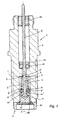
- the in Fig. 1 Prior art piezoelectric pressure sensor 1 shown has piezoelectric measuring elements 3 arranged in a housing 2, which are pretensioned between a membrane element 4 and a housing base 5.
- the membrane element 4 is welded to the outer membrane flange 14 with the pressure-side end of the housing 2.
- the membrane element 4 has a central membrane stamp 15 and a thin, circular membrane 16, which merges into the membrane flange 14 in one piece.
- the piezoelectric measuring elements 3 are radially outside of a substantially along the sensor longitudinal axis 1 'arranged biasing element 8, which biases the piezoelectric measuring elements 3 against the housing base 5.
- two parallel measuring element platelets 3 are arranged, several, for example, three measuring element platelets in the form of a triangle can be arranged equidistant from the biasing element 8 (see Fig. 2 to Fig. 4 ).
- the housing 2 may be made in several parts and e.g. along the line T have a pitch at which the housing parts are welded together after mounting the measuring elements 3.
- the piezoelectric measuring elements 3 have at their narrow sides 6 an annular Ableitelektrode 9, and in the direction of the membrane element 4, an electrical insulating element 10, wherein an electrically conductive connection between the biasing member 8 and the Ableitelektrode 9 is made, so that the central biasing member 8 at the same time Signal derivation is used.
- the measurement is carried out in relation to the housing ground.
- the biasing member 8 passes through the discharge electrode 9 and the insulating member 10 through each through openings 9 ', 10', wherein the biasing member 8 is anchored with a conical extension 11 in the insulating member 10 and against a further insulating 10 on the housing base 5 opposite side of the sensor housing. 2 is biased.
- the biasing elements 8 is held by a fixing elements 12 in the prestressed position, wherein the fixing element 12 may be screwed or welded to the central biasing member 8.
- the biasing element 8 which simultaneously serves the signal derivation, exits at the opposite side of the membrane 4 of the sensor housing 2 by an insulating member 13 which, like the insulating elements 10 may be made of ceramic.
- FIG Fig. 5 The situation in the gap 22 between the pressure piece 17 and the inner wall of the housing 2 is shown in detail in FIG Fig. 5 shown.
- the surfaces of the sealing shoulder 19 and the sealing seat 20 close to the axis 1 'of the pressure sensor 1 each have an acute angle and are coordinated such that the two Parts 15, 17 - after the destruction of the measuring elements 3 - in a pressure surge from the combustion chamber wedged or tighten.
- the central membrane stamp 15 may be connected to the pressure piece 17, for example, by welding, gluing, screwing or shrink fit.
- the pressure piece 17 has a bore 23 which passes through the preload element 8 with play, wherein in a diaphragm-side receptacle 24 of the pressure piece 17, an insulating washer 25 and a fixing member 26 (for example, a nut) are arranged for fixing the biasing member 8.
- the measuring elements 3 are on the housing base 5 side facing with a thin Ableitelektrode 27 in contact, which contacts the biasing member 8 and is electrically insulated by an insulating 28 to the housing base 5.
- a cylindrical insulating sleeve 29, for example made of plastic, is arranged, which serves as a centering aid during assembly.
- the housing 2 which is arranged with play in an outer housing 2 ', has a disk-shaped flange 30, which is welded to the diaphragm flange 14.
- the individual parts 2, 2 'of the housing are also welded together in the flange area.
- the pressure sensor 1 can be inserted into a measuring bore (not shown here) or screwed in with the aid of an external thread of the outer housing 2 '.
Landscapes
- Chemical & Material Sciences (AREA)
- Engineering & Computer Science (AREA)
- Combustion & Propulsion (AREA)
- Physics & Mathematics (AREA)
- General Physics & Mathematics (AREA)
- Measuring Fluid Pressure (AREA)
Description
- Die Erfindung betrifft einen piezoelektrischen Drucksensor mit in einem Gehäuse eingesetzten piezoelektrischen Messelementen und einem druckseitig am Gehäuse angeordneten Membranelement, welches im Zentrum einer dünnen kreisringförmigen Membran einen zentralen Membranstempel aufweist, wobei die piezoelektrischen Messelemente radial außerhalb eines im Wesentlichen entlang der Sensorlängsachse eingesetzten Vorspannelementes angeordnet sind, welches die Gehäusebasis durchsetzt, zur Signalableitung dient und am membranseitigen Ende mit einem Druckstück verbunden ist.
- Piezoelektrische Drucksensoren benötigen für eine hohe Linearität des Messsignals eine mechanische Vorspannung der piezoelektrischen Messelemente. Diese Vorspannung kann beispielsweise durch eine sogenannten Rohrfeder aufgebracht werden, welche die Messelemente umfasst, d.h. im Wesentlichen in einen zylindrischen Innenraum einschließt. Wie beispielsweise in
Fig. 1 derEP 0 745 835 A2 dargestellt, dient die Rohrfeder dazu, die piezoelektrischen Messelemente sicher aneinander zu pressen, wobei die Rohrfeder möglichst massearm und elastisch als dünner Zylinder ausgeführt ist. Die Herstellung und der Einbau einer Rohrfeder ist allerdings aufwändig, so dass Verbesserungen angestrebt wurden. - Bei ungekühlten Drucksensoren kann zumindest für einen beschränkten Zeitraum die Vorspannung auch durch die Membran selbst aufgebracht werden, welche allerdings durch die bei Hochtemperatursensoren auftretenden Temperaturbelastungen (Temperaturen über 400°C) Spannungsverluste erleidet, die zu einer Veränderung der Sensorempfindlichkeit und zu einer Verschlechterung der Linearität führen. Die vorliegende Erfindung bezieht sich daher ausschließlich auf Drucksensoren mit separatem Vorspannelement.
- Aus einer älteren Anmeldung (A 641/2006) ist es gemäß einer Ausführungsvariante bekannt, ein inneres Vorspannelement vorzusehen, bei welchem das zentrale Vorspannelement zur Signalableitung dient, wobei die Messelemente radial außerhalb des Vorspannelementes angeordnet sind. Eine derartige Ausführungsvariante gemäß Stand der Technik wird nachfolgend in
Fig. 1 näher beschrieben. - Derartige Drucksensoren werden beispielsweise zur Dauerüberwachung von Brennkraftmaschinen eingesetzt und müssen dazu hohe Standzeiten von bis zu, bzw. über 20.000 Stunden erreichen, um möglichst große Serviceintervalle garantieren zu können. Die Brennkraftmaschinen sind meist im Dauerbetrieb zur Stromerzeugung, Wärmeerzeugung oder zum Antrieb von Kraftfahrzeugen im Einsatz.
- Die genannten Drucksensoren verwenden brennraumseitig flexible Membranen, die unter sehr ungünstigen Verhältnissen brechen können, wobei Teile der Membran in den Brennraum gelangen können und eine Verbindung zwischen Brennraum und Umgebung entstehen kann. Austretende Flammen und Druckwellen können große Schäden verursachen, sowie Mensch und Maschine gefährden.
- Aufgabe der Erfindung ist es, bekannte Drucksensoren mit innenliegender Vorspannung derart zu verbessern, dass selbst bei Membranbruch vom Drucksensor keine Gefahren ausgehen und ein sicherer Betrieb einer mit dem Drucksensor ausgestatteten Vorrichtung gewährleistet ist.
- Erfindungsgemäß wird diese Aufgabe dadurch gelöst, dass der zentrale Membranstempel am Druckstück befestigt ist und dass das Vorspannelement unter Zwischenlage eines gasdichten Isolierelementes an der Gehäusebasis vorgespannt ist.
- Gemäß einer weiteren Ausgestaltung der Erfindung weist das Druckstück eine Dichtschulter auf, die bei einem Bruch der Messelemente an einem Dichtsitz im Inneren des Gehäuses anliegt und eine gasdichte Zone bildet.
- Beim Versagen des Membranelementes sind zwei Schadensfälle zu unterscheiden:
- a) die kreisringförmige Membran des Membranelementes ist gebrochen, aber die Messelemente sind noch intakt, d.h., das Vorspannelement, das sich über die Messelemente abstützt hält den Brennraum mit Hilfe des gasdichten Isolierelementes an der Gehäusebasis dicht;
- b) sowohl die kreisringförmige Membran des Membranelementes als auch die Messelemente sind zerstört, wodurch das Vorspannelement gelockert wird und nicht mehr abdichtet, wobei jedoch die spezielle Ausformung des Druckstückes mit seiner Dichtschulter gegen das Sensorgehäuse abdichtet.
- Die beiden Schadensfälle a) und b) bei Membrandurchbruch werden in den
Fig. 4 und Fig. 5 im Detail dargestellt. Es zeigen: - Fig. 1
- einen piezoelektrischen Drucksensor in einem Axialschnitt gemäß Stand der Technik;
- Fig. 2
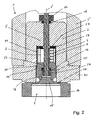
- einen erfindungsgemäßen Drucksensor in einem Axialschnitt mit intaktem Membranelement;
- Fig. 3
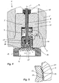
- den erfindungsgemäßen Drucksensor gemäß
Fig. 1 mit gebroche- ner Membran; - Fig. 4
- den Drucksensor gemäß
Fig. 1 mit gebrochener Membran und ge- brochenen Messelementen; sowie - Fig. 5
- ein Detail A aus
Fig. 4 in vergrößerter Darstellung. - Der in
Fig. 1 dargestellte piezoelektrische Drucksensor 1 gemäß Stand der Technik weist in einem Gehäuse 2 angeordnete, piezoelektrische Messelemente 3 auf, welche zwischen einem Membranelement 4 und einer Gehäusebasis 5 vorgespannt sind. Das Membranelement 4 ist mit dem äußeren Membranflansch 14 mit dem druckseitigen Ende des Gehäuses 2 verschweißt. Das Membranelement 4 weist einen zentralen Membranstempel 15 und eine dünne, kreisförmige Membran 16 auf, welche einstückig in den Membranflansch 14 übergeht. - Die piezoelektrischen Messelemente 3 liegen radial außerhalb eines im Wesentlichen entlang der Sensorlängsachse 1' angeordneten Vorspannelementes 8, welches die piezoelektrischen Messelemente 3 gegen die Gehäusebasis 5 vorspannt. In gleicher Weise wie in
Fig. 1 zwei parallel stehende Messelementplättchen 3 angeordnet sind, können auch mehrere, beispielsweise drei Messelementplättchen in Form eines Dreieckes äquidistant zum Vorspannelement 8 angeordnet sein (sieheFig. 2 bis Fig. 4 ). - Das Gehäuse 2 kann mehrteilig ausgeführt sein und z.B. entlang der Linie T eine Teilung aufweisen, an welcher die Gehäuseteile nach der Montage der Messelemente 3 miteinander verschweißt werden.
- Die piezoelektrischen Messelemente 3 weisen an deren Schmalseiten 6 eine kreisringförmige Ableitelektrode 9, sowie in Richtung des Membranelementes 4 ein elektrisches Isolierelement 10 auf, wobei eine elektrisch leitende Verbindung zwischen dem Vorspannelement 8 und der Ableitelektrode 9 hergestellt ist, so dass das zentrale Vorspannelement 8 gleichzeitig zur Signalableitung dient. Die Messung erfolgt dabei in Bezug auf die Gehäusemasse.
- Das Vorspannelement 8 durchsetzt die Ableitelektrode 9 und das Isolierelement 10 jeweils durch Durchtrittsöffnungen 9', 10', wobei das Vorspannelement 8 mit einer konischen Erweiterung 11 im Isolierelement 10 verankert ist und gegen ein weiters Isolierelemente 10 an der der Gehäusebasis 5 gegenüberliegenden Seite des Sensorgehäuses 2 vorgespannt ist. Das Vorspannelemente 8 wird durch ein Fixierelemente 12 in der vorgespannten Stellung gehalten, wobei das Fixierelement 12 mit dem zentralen Vorspannelement 8 verschraubt oder verschweißt sein kann.
- Das Vorspannelement 8, welches gleichzeitig der Signalableitung dient, tritt an der der Membran 4 gegenüberliegenden Seite des Sensorgehäuses 2 durch ein Isolierelement 13 aus, welches wie die Isolierelemente 10 aus Keramik bestehen kann.
- Bei einem Einsatz des Sensors in der Brennraumwand einer hier nicht dargestellten Brennkraftmaschine, kann bei einem Membranbruch, d.h. bei einer Zerstörung der dünnen, kreisringförmigen Membran 16 des Membranelementes 4, der Membranstempel 15 in den Brennraum fallen und dort Schäden verursachen. Weiters können heiße Abgase in das Innere des Drucksensors eindringen. Bei einer längeren Einwirkung der heißen Abgase auf die Messelemente 3 werden diese zerstört, so dass sich das Vorspannelemente 8 nicht mehr an den Messelementen 3 abstützen kann und es zu einer Lockerung des Vorspannelementes 8, sowie zu einer Zerstörung der Isolierelemente 10, 13 kommt. Das kann in der Folge zur Freisetzung von heißen Abgasen und Flammen aus dem Brennraum führen.
- Der in den
Fig. 2 bis Fig. 5 dargestellte, erfindungsgemäße piezoelektrische Drucksensor 1 weist folgende Verbesserungen auf, um selbst im Falle eines Membranbruches die oben beschriebenen Folgeschäden zu verhindern: - Der zentrale Membranstempel 15 ist am Druckstück 17 befestigt, wodurch dieser - selbst bei einem Membranbruch - nicht in das Innere der Brennkammer eines Motors gelangen kann.
- Das Vorspannelement 8 ist unter Zwischenlage eines gasdichten Isolierelementes 18 an der Gehäusebasis 5 vorgespannt. Wie in
Fig. 3 dargestellt, kann bei diesem Szenario das heiße Abgas (dargestellte als schwarze Punkte) nur bis zum Isolierelement 18 gelangen, jedoch den Drucksensor nicht verlassen. Das System bleibt somit selbst bei einem Membranbruch zur Umgebung gasdicht. - Das Druckstück 17 weist eine Dichtschulter 19 auf, die bei einem Bruch der Membran 16 und der Messelemente 3 (siehe
Fig. 4 ) an einem Dichtsitz 20 im Inneren des Gehäuses 2 anliegt, sobald das Druckstück 17 von dem im Brennraum herrschenden Druck in Richtung des Pfeils 21 bewegt wird und eine gasdichte Zone ausbildet. - Die Situation im Spalt 22 zwischen Druckstück 17 und Innenwand des Gehäuses 2 ist im Detail in
Fig. 5 dargestellt. Die Flächen der Dichtschulter 19 und des Dichtsitzes 20 schließen mit der Achse 1' des Drucksensors 1 jeweils einen spitzen Winkel ein und sind derart aufeinander abgestimmt, dass sich die beiden Teile 15, 17 - nach der Zerstörung der Messelemente 3 - bei einem Druckstoß aus dem Brennraum ineinander verkeilen bzw. festreiben. - Der zentrale Membranstempel 15 kann beispielsweise durch Schweißen, Kleben, Schrauben oder eine Schrumpfpassung mit dem Druckstück 17 verbunden sein.
- Erfindungsgemäß weist das Druckstück 17 eine Bohrung 23 auf, welche das Vorspannelement 8 mit Spiel durchsetzt, wobei in einer membranseitigen Aufnahme 24 des Druckstückes 17 eine Isolierscheibe 25 und ein Fixierelement 26 (beispielsweise eine Mutter) zur Festlegung des Vorspannelementes 8 angeordnet sind.
- Die Messelemente 3 stehen auf der der Gehäusebasis 5 zugewandten Seite mit einer dünnen Ableitelektrode 27 in Kontakt, die das Vorspannelement 8 kontaktiert und durch eine Isolierscheibe 28 zur Gehäusebasis 5 elektrisch isoliert ist. An der Außenseite der Messelemente 3 ist eine zylindrische Isolierhülse 29, beispielsweise aus Kunststoff, angeordnet, welche während der Montage als Zentrierhilfe dient.
- Das Gehäuse 2, welches mit Spiel in einem Außengehäuse 2' angeordnet ist, weist einen scheibenförmigen Flansch 30 auf, der mit dem Membranflansch 14 verschweißt ist. Die einzelnen Teile 2, 2' des Gehäuses werden ebenfalls im Flanschbereich miteinander verschweißt. Der Drucksensor 1 kann in eine (hier nicht dargestellte) Messbohrung eingesteckt oder mit Hilfe eines Außengewindes des Außengehäuses 2' eingeschraubt sein.
Claims (5)
- Piezoelektrischer Drucksensor (1) mit in einem Gehäuse (2) eingesetzten piezoelektrischen Messelementen (3) und einem druckseitig am Gehäuse (2) angeordneten Membranelement (4), welches im Zentrum einer dünnen kreisringförmigen Membran (16) einen zentralen Membranstempel (15) aufweist, wobei die piezoelektrischen Messelemente (3) radial außerhalb eines im Wesentlichen entlang der Sensorlängsachse (1') eingesetzten Vorspannelementes (8) angeordnet sind, welches die Gehäusebasis (5) durchsetzt, zur Signalableitung dient und am membranseitigen Ende mit einem Druckstück (17) verbunden ist, dadurch gekennzeichnet, dass der zentrale Membranstempel (15) am Druckstück (17) befestigt ist und dass das Vorspannelement (8) unter Zwischenlage eines gasdichten Isolierelementes (18) an der Gehäusebasis (5) vorgespannt ist.
- Piezoelektrischer Drucksensor (1) nach Anspruch 1, dadurch gekennzeichnet, dass das Druckstück (17) eine Dichtschulter (19) aufweist, die bei einem Bruch der Messelemente (3) an einem Dichtsitz (20) im Inneren des Gehäuses (2) anliegt und eine gasdichte Zone bildet.
- Piezoelektrischer Drucksensor (1) nach Anspruch 1 oder 2, dadurch gekennzeichnet, dass das Druckstück (17) eine Bohrung (23) aufweist, welche das Vorspannelement (8) mit Spiel durchsetzt, sowie dass in einer membranseitigen Aufnahme (24) des Druckstückes (17) eine Isolierscheibe (25) und ein Fixierelement (26) zur Festlegung des Vorspannelementes (8) angeordnet sind.
- Piezoelektrischer Drucksensor (1) nach einem der Ansprüche 1 bis 3, dadurch gekennzeichnet, dass die Messelemente (3) auf der der Gehäusebasis (5) zugewandten Seite mit einer Ableitelektrode (27) in Kontakt stehen, wobei die Ableitelektrode (27) das Vorspannelement (8) kontaktiert und durch eine Isolierscheibe (28) zur Gehäusebasis (5) elektrisch isoliert ist.
- Piezoelektrischer Drucksensor (1) nach einem der Ansprüche 1 bis 4, dadurch gekennzeichnet, dass die Messelemente (3) in einer zylindrischen Isolierhülse (29) angeordnet sind.
Applications Claiming Priority (2)
| Application Number | Priority Date | Filing Date | Title |
|---|---|---|---|
| AT0118707A AT505015B1 (de) | 2007-07-27 | 2007-07-27 | Drucksensor |
| PCT/EP2008/057925 WO2009015941A1 (de) | 2007-07-27 | 2008-06-23 | Piezoelektrischer drucksensor |
Publications (2)
| Publication Number | Publication Date |
|---|---|
| EP2174107A1 EP2174107A1 (de) | 2010-04-14 |
| EP2174107B1 true EP2174107B1 (de) | 2010-10-27 |
Family
ID=39830282
Family Applications (1)
| Application Number | Title | Priority Date | Filing Date |
|---|---|---|---|
| EP08761293A Not-in-force EP2174107B1 (de) | 2007-07-27 | 2008-06-23 | Piezoelektrischer drucksensor |
Country Status (6)
| Country | Link |
|---|---|
| US (1) | US20100263451A1 (de) |
| EP (1) | EP2174107B1 (de) |
| AT (2) | AT505015B1 (de) |
| DE (1) | DE502008001669D1 (de) |
| DK (1) | DK2174107T3 (de) |
| WO (1) | WO2009015941A1 (de) |
Cited By (1)
| Publication number | Priority date | Publication date | Assignee | Title |
|---|---|---|---|---|
| EP2843385A1 (de) | 2013-08-30 | 2015-03-04 | Piezocryst Advanced Sensorics GmbH | Drucksensor |
Families Citing this family (9)
| Publication number | Priority date | Publication date | Assignee | Title |
|---|---|---|---|---|
| US8490497B2 (en) * | 2010-03-25 | 2013-07-23 | University Of Southern California | Microelectromechanical (MEMS) pressure transducer |
| CN102235932B (zh) * | 2010-04-28 | 2012-12-05 | 雷彼得 | 有金属陶瓷电热体的内燃机气缸压力传感器 |
| CH705470A1 (de) * | 2011-09-07 | 2013-03-15 | Kistler Holding Ag | Durchbruchsicherer Drucksensor. |
| EP3124944B1 (de) * | 2015-07-31 | 2019-01-23 | Kistler Holding AG | Piezoelektrischer drucksensor |
| DK3124943T3 (da) * | 2015-07-31 | 2021-08-30 | Kistler Holding Ag | Piezoelektrisk tryksensor og fremgangsmåde til fremstilling af den piezoelektriske tryksensor |
| EP3124945B1 (de) * | 2015-07-31 | 2018-09-12 | Kistler Holding AG | Piezoelektrischer drucksensor |
| AT518650B1 (de) | 2016-06-07 | 2017-12-15 | Piezocryst Advanced Sensorics | Piezoelektrischer drucksensor zum messen hoher drücke |
| KR102574986B1 (ko) * | 2016-12-16 | 2023-09-05 | 에이치에스디엔진 주식회사 | 압력 센서 모듈 |
| AT523511B1 (de) * | 2020-01-29 | 2021-10-15 | Piezocryst Advanced Sensorics | Strukturiertes, piezoelektrisches Sensorelement |
Family Cites Families (15)
| Publication number | Priority date | Publication date | Assignee | Title |
|---|---|---|---|---|
| FR1031155A (fr) * | 1951-01-18 | 1953-06-22 | Perfectionnements apportés aux dispositifs de mesure des pressions | |
| CH424312A (de) * | 1964-08-15 | 1966-11-15 | Kistler Instrumente Ag | Beschleunigungskompensierter piezoelektrischer Messwandler |
| CH582353A5 (de) * | 1974-11-08 | 1976-11-30 | Kistler Instrumente Ag | |
| ATE17523T1 (de) * | 1982-04-06 | 1986-02-15 | Kistler Instrumente Ag | Hochdruckaufnehmer. |
| AT384676B (de) * | 1983-07-07 | 1987-12-28 | Avl Verbrennungskraft Messtech | Messwertaufnehmer zur messung heisser medien und verfahren zur montage eines als druckaufnehmerausgebildeten messwertaufnehmers |
| US4567395A (en) * | 1984-10-26 | 1986-01-28 | Texas Instruments Incorporated | Piezoelectric pressure transmitter for an internal combustion engine |
| EP0230491B1 (de) * | 1986-01-22 | 1989-05-03 | Kristal Instrumente AG | Aufnehmer, insbesondere für Hochdruckmessungen |
| DE8903667U1 (de) * | 1989-03-23 | 1989-05-11 | Kistler Instrumente Ag, Winterthur | Hochdruckaufnehmer |
| AT394112B (de) * | 1989-03-30 | 1992-02-10 | Avl Verbrennungskraft Messtech | Druckaufnehmer |
| JPH04131722A (ja) * | 1990-09-21 | 1992-05-06 | Toyota Motor Corp | 圧力センサ及び圧力センサの製造方法 |
| JPH0694561A (ja) * | 1992-09-11 | 1994-04-05 | Matsushita Electric Ind Co Ltd | 圧電型圧力センサ |
| EP0637736A3 (de) * | 1993-08-05 | 1995-05-10 | Matsushita Electric Industrial Co Ltd | Piezoelektrischer Drucksensor und Verfahren zu seiner Herstellung. |
| AT401972B (de) * | 1995-06-02 | 1997-01-27 | Avl Verbrennungskraft Messtech | Ungekühlter drucksensor |
| AT503664B1 (de) * | 2006-04-13 | 2007-12-15 | Piezocryst Advanced Sensorics | Piezoelektrischer drucksensor |
| AT503816B1 (de) * | 2006-06-06 | 2008-01-15 | Piezocryst Advanced Sensorics | Piezoelektrischer sensor |
-
2007
- 2007-07-27 AT AT0118707A patent/AT505015B1/de not_active IP Right Cessation
-
2008
- 2008-06-23 DK DK08761293.3T patent/DK2174107T3/da active
- 2008-06-23 WO PCT/EP2008/057925 patent/WO2009015941A1/de not_active Ceased
- 2008-06-23 US US12/452,880 patent/US20100263451A1/en not_active Abandoned
- 2008-06-23 DE DE502008001669T patent/DE502008001669D1/de active Active
- 2008-06-23 EP EP08761293A patent/EP2174107B1/de not_active Not-in-force
- 2008-06-23 AT AT08761293T patent/ATE486273T1/de active
Cited By (1)
| Publication number | Priority date | Publication date | Assignee | Title |
|---|---|---|---|---|
| EP2843385A1 (de) | 2013-08-30 | 2015-03-04 | Piezocryst Advanced Sensorics GmbH | Drucksensor |
Also Published As
| Publication number | Publication date |
|---|---|
| DE502008001669D1 (de) | 2010-12-09 |
| AT505015A4 (de) | 2008-10-15 |
| WO2009015941A1 (de) | 2009-02-05 |
| WO2009015941A8 (de) | 2010-02-04 |
| EP2174107A1 (de) | 2010-04-14 |
| ATE486273T1 (de) | 2010-11-15 |
| DK2174107T3 (da) | 2011-02-07 |
| AT505015B1 (de) | 2008-10-15 |
| US20100263451A1 (en) | 2010-10-21 |
Similar Documents
| Publication | Publication Date | Title |
|---|---|---|
| EP2174107B1 (de) | Piezoelektrischer drucksensor | |
| CH698578B1 (de) | Piezoelektrischer Drucksensor. | |
| EP2843385B1 (de) | Drucksensor | |
| EP0230491B1 (de) | Aufnehmer, insbesondere für Hochdruckmessungen | |
| EP2174106B2 (de) | Kraftsensor | |
| EP3176555B1 (de) | Piezoelektrischer drucksensor und verfahren zur herstellung eines solchen drucksensors | |
| DE3423711C2 (de) | Meßwertaufnehmer zur Messung heißer Medien, sowie Verfahren zu seiner Montage | |
| AT407577B (de) | Zündkerze mit einer druckmesseinrichtung | |
| EP0226742B1 (de) | Druckaufnehmer für Druckmessungen unter hohen Temperaturen | |
| EP3255401B1 (de) | Piezoelektrischer drucksensor zum messen hoher drücke | |
| EP1646268B1 (de) | Spannvorrichtung für Hochspannungskabel | |
| EP0811833A1 (de) | Drucksensor für gasförmige und/oder flüssige Medien | |
| DE19524147C2 (de) | Schwingungsaufnehmer mit einer Druckhülse | |
| EP3285057B1 (de) | Drucksensor für hohe drücke | |
| DE1124729B (de) | Vorrichtung zum Messen der Kraefte zwischen Bauteilen | |
| EP1508947A1 (de) | Zündkerze für eine Brennkraftmaschine | |
| EP1875135B1 (de) | Glühstiftkerze mit brennraumdrucksensor und dichtelement | |
| EP1322928A1 (de) | Schwingungsaufnehmner zur mittelbaren oder unmittelbaren befestigung an einem schwingungen aufweisenden bauteil | |
| EP3179090B1 (de) | Kraftstoffinjektor | |
| AT523625B1 (de) | Drucksensor | |
| EP3607623B1 (de) | Zündkerze mit verbesserter dichtheit | |
| EP0715159A2 (de) | Drucksensor für flüssige oder gasförmige Medien | |
| EP4478389A1 (de) | Baugruppe für den potenzialausgleich in explosionsgefährdeten bereichen | |
| AT9920U1 (de) | Kraftsensor | |
| DE102020209858A1 (de) | Zündkerze mit Dichtscheibe und Dichtscheibe für eine Zündkerze |
Legal Events
| Date | Code | Title | Description |
|---|---|---|---|
| PUAI | Public reference made under article 153(3) epc to a published international application that has entered the european phase |
Free format text: ORIGINAL CODE: 0009012 |
|
| 17P | Request for examination filed |
Effective date: 20100113 |
|
| AK | Designated contracting states |
Kind code of ref document: A1 Designated state(s): AT BE BG CH CY CZ DE DK EE ES FI FR GB GR HR HU IE IS IT LI LT LU LV MC MT NL NO PL PT RO SE SI SK TR |
|
| AX | Request for extension of the european patent |
Extension state: AL BA MK RS |
|
| GRAP | Despatch of communication of intention to grant a patent |
Free format text: ORIGINAL CODE: EPIDOSNIGR1 |
|
| GRAS | Grant fee paid |
Free format text: ORIGINAL CODE: EPIDOSNIGR3 |
|
| GRAA | (expected) grant |
Free format text: ORIGINAL CODE: 0009210 |
|
| AK | Designated contracting states |
Kind code of ref document: B1 Designated state(s): AT BE BG CH CY CZ DE DK EE ES FI FR GB GR HR HU IE IS IT LI LT LU LV MC MT NL NO PL PT RO SE SI SK TR |
|
| REG | Reference to a national code |
Ref country code: GB Ref legal event code: FG4D Free format text: NOT ENGLISH |
|
| REG | Reference to a national code |
Ref country code: CH Ref legal event code: EP |
|
| REG | Reference to a national code |
Ref country code: CH Ref legal event code: NV Representative=s name: ISLER & PEDRAZZINI AG |
|
| REG | Reference to a national code |
Ref country code: IE Ref legal event code: FG4D Free format text: LANGUAGE OF EP DOCUMENT: GERMAN |
|
| REF | Corresponds to: |
Ref document number: 502008001669 Country of ref document: DE Date of ref document: 20101209 Kind code of ref document: P |
|
| REG | Reference to a national code |
Ref country code: DK Ref legal event code: T3 |
|
| REG | Reference to a national code |
Ref country code: NL Ref legal event code: VDEP Effective date: 20101027 |
|
| LTIE | Lt: invalidation of european patent or patent extension |
Effective date: 20101027 |
|
| REG | Reference to a national code |
Ref country code: NO Ref legal event code: T2 Effective date: 20101027 |
|
| PG25 | Lapsed in a contracting state [announced via postgrant information from national office to epo] |
Ref country code: LT Free format text: LAPSE BECAUSE OF FAILURE TO SUBMIT A TRANSLATION OF THE DESCRIPTION OR TO PAY THE FEE WITHIN THE PRESCRIBED TIME-LIMIT Effective date: 20101027 |
|
| REG | Reference to a national code |
Ref country code: IE Ref legal event code: FD4D |
|
| PG25 | Lapsed in a contracting state [announced via postgrant information from national office to epo] |
Ref country code: SI Free format text: LAPSE BECAUSE OF FAILURE TO SUBMIT A TRANSLATION OF THE DESCRIPTION OR TO PAY THE FEE WITHIN THE PRESCRIBED TIME-LIMIT Effective date: 20101027 Ref country code: BG Free format text: LAPSE BECAUSE OF FAILURE TO SUBMIT A TRANSLATION OF THE DESCRIPTION OR TO PAY THE FEE WITHIN THE PRESCRIBED TIME-LIMIT Effective date: 20110127 Ref country code: LV Free format text: LAPSE BECAUSE OF FAILURE TO SUBMIT A TRANSLATION OF THE DESCRIPTION OR TO PAY THE FEE WITHIN THE PRESCRIBED TIME-LIMIT Effective date: 20101027 Ref country code: SE Free format text: LAPSE BECAUSE OF FAILURE TO SUBMIT A TRANSLATION OF THE DESCRIPTION OR TO PAY THE FEE WITHIN THE PRESCRIBED TIME-LIMIT Effective date: 20101027 Ref country code: HR Free format text: LAPSE BECAUSE OF FAILURE TO SUBMIT A TRANSLATION OF THE DESCRIPTION OR TO PAY THE FEE WITHIN THE PRESCRIBED TIME-LIMIT Effective date: 20101027 Ref country code: IS Free format text: LAPSE BECAUSE OF FAILURE TO SUBMIT A TRANSLATION OF THE DESCRIPTION OR TO PAY THE FEE WITHIN THE PRESCRIBED TIME-LIMIT Effective date: 20110227 Ref country code: PT Free format text: LAPSE BECAUSE OF FAILURE TO SUBMIT A TRANSLATION OF THE DESCRIPTION OR TO PAY THE FEE WITHIN THE PRESCRIBED TIME-LIMIT Effective date: 20110228 Ref country code: NL Free format text: LAPSE BECAUSE OF FAILURE TO SUBMIT A TRANSLATION OF THE DESCRIPTION OR TO PAY THE FEE WITHIN THE PRESCRIBED TIME-LIMIT Effective date: 20101027 |
|
| PG25 | Lapsed in a contracting state [announced via postgrant information from national office to epo] |
Ref country code: GR Free format text: LAPSE BECAUSE OF FAILURE TO SUBMIT A TRANSLATION OF THE DESCRIPTION OR TO PAY THE FEE WITHIN THE PRESCRIBED TIME-LIMIT Effective date: 20110128 |
|
| PG25 | Lapsed in a contracting state [announced via postgrant information from national office to epo] |
Ref country code: CZ Free format text: LAPSE BECAUSE OF FAILURE TO SUBMIT A TRANSLATION OF THE DESCRIPTION OR TO PAY THE FEE WITHIN THE PRESCRIBED TIME-LIMIT Effective date: 20101027 Ref country code: IE Free format text: LAPSE BECAUSE OF FAILURE TO SUBMIT A TRANSLATION OF THE DESCRIPTION OR TO PAY THE FEE WITHIN THE PRESCRIBED TIME-LIMIT Effective date: 20101027 Ref country code: EE Free format text: LAPSE BECAUSE OF FAILURE TO SUBMIT A TRANSLATION OF THE DESCRIPTION OR TO PAY THE FEE WITHIN THE PRESCRIBED TIME-LIMIT Effective date: 20101027 Ref country code: ES Free format text: LAPSE BECAUSE OF FAILURE TO SUBMIT A TRANSLATION OF THE DESCRIPTION OR TO PAY THE FEE WITHIN THE PRESCRIBED TIME-LIMIT Effective date: 20110207 |
|
| PG25 | Lapsed in a contracting state [announced via postgrant information from national office to epo] |
Ref country code: SK Free format text: LAPSE BECAUSE OF FAILURE TO SUBMIT A TRANSLATION OF THE DESCRIPTION OR TO PAY THE FEE WITHIN THE PRESCRIBED TIME-LIMIT Effective date: 20101027 Ref country code: RO Free format text: LAPSE BECAUSE OF FAILURE TO SUBMIT A TRANSLATION OF THE DESCRIPTION OR TO PAY THE FEE WITHIN THE PRESCRIBED TIME-LIMIT Effective date: 20101027 Ref country code: PL Free format text: LAPSE BECAUSE OF FAILURE TO SUBMIT A TRANSLATION OF THE DESCRIPTION OR TO PAY THE FEE WITHIN THE PRESCRIBED TIME-LIMIT Effective date: 20101027 |
|
| PLBE | No opposition filed within time limit |
Free format text: ORIGINAL CODE: 0009261 |
|
| STAA | Information on the status of an ep patent application or granted ep patent |
Free format text: STATUS: NO OPPOSITION FILED WITHIN TIME LIMIT |
|
| 26N | No opposition filed |
Effective date: 20110728 |
|
| REG | Reference to a national code |
Ref country code: DE Ref legal event code: R097 Ref document number: 502008001669 Country of ref document: DE Effective date: 20110728 |
|
| PG25 | Lapsed in a contracting state [announced via postgrant information from national office to epo] |
Ref country code: MT Free format text: LAPSE BECAUSE OF FAILURE TO SUBMIT A TRANSLATION OF THE DESCRIPTION OR TO PAY THE FEE WITHIN THE PRESCRIBED TIME-LIMIT Effective date: 20101027 Ref country code: IT Free format text: LAPSE BECAUSE OF FAILURE TO SUBMIT A TRANSLATION OF THE DESCRIPTION OR TO PAY THE FEE WITHIN THE PRESCRIBED TIME-LIMIT Effective date: 20101027 |
|
| BERE | Be: lapsed |
Owner name: PIEZOCRYST ADVANCED SENSORICS GMBH Effective date: 20110630 |
|
| PG25 | Lapsed in a contracting state [announced via postgrant information from national office to epo] |
Ref country code: BE Free format text: LAPSE BECAUSE OF NON-PAYMENT OF DUE FEES Effective date: 20110630 |
|
| PGFP | Annual fee paid to national office [announced via postgrant information from national office to epo] |
Ref country code: GB Payment date: 20120629 Year of fee payment: 5 |
|
| PG25 | Lapsed in a contracting state [announced via postgrant information from national office to epo] |
Ref country code: MC Free format text: LAPSE BECAUSE OF NON-PAYMENT OF DUE FEES Effective date: 20110630 |
|
| PG25 | Lapsed in a contracting state [announced via postgrant information from national office to epo] |
Ref country code: LU Free format text: LAPSE BECAUSE OF NON-PAYMENT OF DUE FEES Effective date: 20110623 Ref country code: CY Free format text: LAPSE BECAUSE OF EXPIRATION OF PROTECTION Effective date: 20101027 |
|
| PGFP | Annual fee paid to national office [announced via postgrant information from national office to epo] |
Ref country code: DK Payment date: 20130628 Year of fee payment: 6 Ref country code: NO Payment date: 20130610 Year of fee payment: 6 |
|
| PGFP | Annual fee paid to national office [announced via postgrant information from national office to epo] |
Ref country code: FI Payment date: 20130613 Year of fee payment: 6 |
|
| PG25 | Lapsed in a contracting state [announced via postgrant information from national office to epo] |
Ref country code: TR Free format text: LAPSE BECAUSE OF FAILURE TO SUBMIT A TRANSLATION OF THE DESCRIPTION OR TO PAY THE FEE WITHIN THE PRESCRIBED TIME-LIMIT Effective date: 20101027 |
|
| PG25 | Lapsed in a contracting state [announced via postgrant information from national office to epo] |
Ref country code: HU Free format text: LAPSE BECAUSE OF FAILURE TO SUBMIT A TRANSLATION OF THE DESCRIPTION OR TO PAY THE FEE WITHIN THE PRESCRIBED TIME-LIMIT Effective date: 20101027 |
|
| PGFP | Annual fee paid to national office [announced via postgrant information from national office to epo] |
Ref country code: FR Payment date: 20130716 Year of fee payment: 6 |
|
| GBPC | Gb: european patent ceased through non-payment of renewal fee |
Effective date: 20130623 |
|
| PG25 | Lapsed in a contracting state [announced via postgrant information from national office to epo] |
Ref country code: GB Free format text: LAPSE BECAUSE OF NON-PAYMENT OF DUE FEES Effective date: 20130623 |
|
| REG | Reference to a national code |
Ref country code: AT Ref legal event code: MM01 Ref document number: 486273 Country of ref document: AT Kind code of ref document: T Effective date: 20130623 |
|
| PG25 | Lapsed in a contracting state [announced via postgrant information from national office to epo] |
Ref country code: AT Free format text: LAPSE BECAUSE OF NON-PAYMENT OF DUE FEES Effective date: 20130623 |
|
| REG | Reference to a national code |
Ref country code: DK Ref legal event code: EBP Effective date: 20140630 |
|
| PG25 | Lapsed in a contracting state [announced via postgrant information from national office to epo] |
Ref country code: FI Free format text: LAPSE BECAUSE OF NON-PAYMENT OF DUE FEES Effective date: 20140623 |
|
| REG | Reference to a national code |
Ref country code: FR Ref legal event code: ST Effective date: 20150227 |
|
| PG25 | Lapsed in a contracting state [announced via postgrant information from national office to epo] |
Ref country code: NO Free format text: LAPSE BECAUSE OF NON-PAYMENT OF DUE FEES Effective date: 20140630 |
|
| PG25 | Lapsed in a contracting state [announced via postgrant information from national office to epo] |
Ref country code: FR Free format text: LAPSE BECAUSE OF NON-PAYMENT OF DUE FEES Effective date: 20140630 |
|
| PG25 | Lapsed in a contracting state [announced via postgrant information from national office to epo] |
Ref country code: DK Free format text: LAPSE BECAUSE OF NON-PAYMENT OF DUE FEES Effective date: 20140630 |
|
| PGFP | Annual fee paid to national office [announced via postgrant information from national office to epo] |
Ref country code: CH Payment date: 20190625 Year of fee payment: 12 |
|
| PGFP | Annual fee paid to national office [announced via postgrant information from national office to epo] |
Ref country code: DE Payment date: 20190830 Year of fee payment: 12 |
|
| REG | Reference to a national code |
Ref country code: DE Ref legal event code: R119 Ref document number: 502008001669 Country of ref document: DE |
|
| REG | Reference to a national code |
Ref country code: CH Ref legal event code: PL |
|
| PG25 | Lapsed in a contracting state [announced via postgrant information from national office to epo] |
Ref country code: LI Free format text: LAPSE BECAUSE OF NON-PAYMENT OF DUE FEES Effective date: 20200630 Ref country code: CH Free format text: LAPSE BECAUSE OF NON-PAYMENT OF DUE FEES Effective date: 20200630 |
|
| PG25 | Lapsed in a contracting state [announced via postgrant information from national office to epo] |
Ref country code: DE Free format text: LAPSE BECAUSE OF NON-PAYMENT OF DUE FEES Effective date: 20210101 |