EP2173617B1 - System for moving and storing a conduit for supplying air to an aircraft - Google Patents
System for moving and storing a conduit for supplying air to an aircraft Download PDFInfo
- Publication number
- EP2173617B1 EP2173617B1 EP08826414A EP08826414A EP2173617B1 EP 2173617 B1 EP2173617 B1 EP 2173617B1 EP 08826414 A EP08826414 A EP 08826414A EP 08826414 A EP08826414 A EP 08826414A EP 2173617 B1 EP2173617 B1 EP 2173617B1
- Authority
- EP
- European Patent Office
- Prior art keywords
- hose
- frame
- base support
- support
- stationary bearing
- Prior art date
- Legal status (The legal status is an assumption and is not a legal conclusion. Google has not performed a legal analysis and makes no representation as to the accuracy of the status listed.)
- Not-in-force
Links
Images


Classifications
-
- B—PERFORMING OPERATIONS; TRANSPORTING
- B64—AIRCRAFT; AVIATION; COSMONAUTICS
- B64F—GROUND OR AIRCRAFT-CARRIER-DECK INSTALLATIONS SPECIALLY ADAPTED FOR USE IN CONNECTION WITH AIRCRAFT; DESIGNING, MANUFACTURING, ASSEMBLING, CLEANING, MAINTAINING OR REPAIRING AIRCRAFT, NOT OTHERWISE PROVIDED FOR; HANDLING, TRANSPORTING, TESTING OR INSPECTING AIRCRAFT COMPONENTS, NOT OTHERWISE PROVIDED FOR
- B64F1/00—Ground or aircraft-carrier-deck installations
- B64F1/36—Other airport installations
- B64F1/362—Installations for supplying conditioned air to parked aircraft
Definitions
- the present invention relates generally to a system and method for connecting a source of preconditioned air to a receiver for the preconditioned air, typically an aircraft. More particularly, the present invention relates to a system for storing and moving a hose leading from the source of preconditioned air to an aircraft. The system reduces the potential for damaging the hose due to sliding friction against components of the system and facilitates efficient storage and dispensing of the hose.
- a connection is made to a ground source that provides heated or air-conditioned air to the aircraft.
- a hose is extended from the preconditioned air source to a standardized hatch door located, generally, on the underside of the aircraft.
- a standard air chute is typically used that mates and locks with the area about the hatch door through a clamping or similar fixed connection system.
- hoses After departure of the aircraft, it is preferable to move the hose to a position where the hose is less likely to be damaged, for example, by airport vehicles or direct exposure to precipitation and other elements.
- Some hoses are provided in multiple detachable segments and, as such, an operator may disassemble the segments for storage.
- Other hoses are flexible and, as such, an operator may fold, roll, or compress the hose into a more compact position for storage.
- such tasks can be time consuming for operators and, thus, may not be consistently performed.
- the prior art storage system 10 includes drive mechanisms 12 that move a flexible hose 14 between a use position and a storage position.
- the hose 14 is axially compressed and supported by a rigid tube 16 in the storage position.
- the drive mechanisms 12 may drive in the opposite direction to push the hose 14 from the tube 16.
- the prior art system 10 optionally includes actuators 18 that release the drive mechanisms 12 from engagement with the hose 14 to permit the hose 14 to be manually pulled from the storage position.
- An example of such a system is known from US2004/0209565 .
- the drive mechanisms of systems such as those shown in Fig. 1 typically result in high friction between the inner surface of the hose 14 and the tube 16.
- the high friction can cause wear on the hose 14 that may render the hose 14 ineffective for supplying preconditioned air.
- providing additional components within the hose, such as the tube increases the weight of the system and the resistance to airflow resulting in reduced airflow efficiency. Therefore, increased power input may be necessary to deliver preconditioned air to the aircraft.
- systems such as those shown in Fig. 1 typically dispense and retract the hose slowly.
- JP 11159849 describes an air duct storage unit with a supporting tube, an air duct holding body for folding and mounting a flexible air duct at a required interval in a longitudinal direction on the outside of the supporting tube, and a flange section of drawing out the air duct by holding a sufficient tensile force with respect to an extending direction of a folded air duct while gradually expanding and opening a folded air duct.
- a bracket encircles an air duct holding body so as to fix a supporting tube externally on an outer circumference of the other thereof with respect to one end of the supporting tube.
- the present invention overcomes the aforementioned drawbacks by providing a light-weight system for moving a preconditioned air hose.
- the system is designed to move the hose without reducing the product life of the hose and permit preconditioned air to be delivered efficiently.
- a system for supporting a hose configured to deliver preconditioned air from a source to an aircraft is provided, as described in appended claim 1.
- a system for supporting a hose configured to deliver preconditioned air from a source to an aircraft includes a base support and a plurality of longitudinal members connected to the base support proximate a first end of the plurality of longitudinal members.
- the plurality of longitudinal members are configured to engage an inner surface of the hose to support the hose.
- the system also includes a frame assembly connected to the plurality of longitudinal members proximate a second end of the plurality of longitudinal members.
- the frame assembly includes a plurality of supports extending away from the frame assembly that are configured to engage the inner surface of the hose.
- a kit for retrofitting a system for supporting a hose for delivering preconditioned air to an aircraft includes a base support and a stationary bearing assembly configured to connect to the base support and extend from base support in a travel direction of the hose.
- the stationary bearing assembly is configured to engage the hose to support the hose.
- the kit also includes a frame assembly configured to connect to the stationary bearing assembly at a position spaced apart from the base support in the travel direction of the hose.
- the frame assembly includes a support extending away from the frame assembly that is configured to engage the hose.
- Fig. 1 is a cross-sectional view of a prior art system for moving a flexible hose for providing preconditioned air to an aircraft;
- Fig. 2 is a side-elevational view of a system for moving a preconditioned air hose in accordance with the present invention
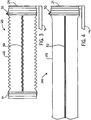
- Fig. 3 is a side-elevational view of the system of Fig. 2 with a preconditioned air hose in a storage position;
- Fig. 4 is a side-elevational view of the system of Fig. 2 with the preconditioned air hose in a deployed position;
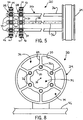
- Fig. 5 is a top view of the system of Fig. 2 ;
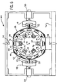
- Fig. 6 is a front view of the system of Fig. 2 in addition to a frame and grippers;
- Fig. 7 is a front view of system of Fig. 2 in addition to a frame and retraction rollers;
- Fig. 8 is a rear view of the system of Fig. 2 .
- a system 20 for supporting a preconditioned air hose 22 includes a base support 24 that fixedly connects to an end of the hose 22 and a stationary bearing assembly 26 and frame assemblies 28 that engage the hose 22.
- the hose 22 moves between a storage position, as shown in Fig. 3 , in which the hose 22 is axially compressed along the stationary bearing assembly 26, and a deployed position, as shown in Fig. 4 , in which the hose 22 delivers preconditioned air from an air source (not shown) to an aircraft (not shown). In the deployed position, the hose 22 is supported by the frame assemblies 28.
- the base support 24 is a generally circular member that fixedly connects to an end of the hose 22 by a hose clamp 30 or other similar component.
- the end of the base support 24 opposite the hose 22 connects to the air source or a conduit in fluid communication with the air source.
- the base support 24 includes a plurality of support holes, two of which are indicated by reference numeral 32, to connect the stationary bearing assembly 26.
- the support holes 32 are advantageously spaced about the circumference of a base circle at generally equal angles from one another. For example, in the configuration shown in Fig. 8 , six support holes 32 are spaced about 60 degrees from one another.
- the base circle has a diameter of about 8.75 inches to properly accommodate the hose 22.
- the diameter of the base circle may be varied without departing from the scope of the present invention.
- the base support 24 advantageously has thin walls 25 as viewed in Fig. 8 .
- the walls 25 define a plurality of passages 34 that permit air to pass from one side of the base support 24 to the other.
- the stationary bearing assembly 26 defines a longitudinal axis 35 in the direction in which the hose 22 generally moves.
- the stationary bearing assembly 26 advantageously includes a plurality of longitudinal members 36 that engage the hose 22.
- Each longitudinal member 36 connects to the base support 24 by a single support hole 32.
- the longitudinal members 36 define a generally hexagonal-shaped cross-sectional area with generally equal side lengths. That is, the longitudinal members 36 are spaced about the longitudinal axis 35 at generally equal angels from one another.
- the longitudinal members 36 provide low resistance to airflow through the system 20 resulting in high airflow efficiency.
- the longitudinal members 36 are light-weight compared to similar components in prior-art designs.
- a first of the frame assemblies 28 connects to the stationary bearing assembly 26 near an end opposite the base support 24.
- a second of the frame assemblies 28 connects to and is positioned along the stationary bearing assembly 26 between the first frame assembly 28 and the base support 24.
- the second frame assembly 28 is advantageously closer to the first frame assembly 28 than the base support 24.
- the first frame assembly 28 is fixed relative to the longitudinal members 36 by collars 37 connected to three of the longitudinal members 36.
- the second frame assembly 28 is fixed relative to the longitudinal members 36 by collars 37 connected to the other three of the longitudinal members 36.
- the first frame assembly 28 includes a generally annular-shaped member 38 having a plurality of mounting sections 40 that each engage a single longitudinal member 36.
- the frame assembly 28 also includes a plurality of supports, two of which are indicated by the reference numeral 42, to engage the hose 22.
- the supports 42 extend radially outwardly from the annular-shaped member 38.
- the supports 42 may be a friction reducing bearing, which should be understood as a wear material with a low coefficient of friction, a support that includes a roller element, or, as shown in the figures, a support that includes a ball element 44.
- the supports 42 define a cross-sectional area larger than the hexagonal area defined by the longitudinal members 36 and thereby limit the amount of friction between components of the system 20 and the hose 22. Limiting the amount of friction reduces the amount of wear experienced by the hose 22.
- At least one, advantageously more than one of the supports 42' are biased radially outwardly from the annular-shaped member 38, for example, by springs 43.
- Spring-biased supports 42' advantageously compensate for variations in hose diameter due to manufacturing processes.
- Spring-biased supports 42' also hold the hose 22 in a taut configuration which in turn holds the hose 22 in a proper orientation as it passes over the frame assembly 28. This aspect of the invention will be described in further detail below.
- the supports 42' to the sides of the supports 42 at the 12 o'clock and 6 o'clock positions are advantageously spring-biased supports 42' because of deflection due to the cantilevered configuration of the stationary bearing assembly 26.
- the base support 24 connects to a frame 46 that connects to a lower surface of a jetway (not shown) or similar structure to support the system 20.
- the frame 46 may include joints or other components that permit the system 20 to pivot about vertical and horizontal axes relative to the lower surface of the jetway.
- the frame 46 includes grippers 48 that move between open and closed positions to engage a portion of the hose 22. Actuators 50 move the grippers 48 generally in the direction of the longitudinal axis 35.
- the actuators 50 may be pneumatic actuators, hydraulic actuators, power screws, solenoid actuators, or any other type of linear actuator known in the art.
- the grippers 48 may take many forms.
- the grippers 48 move in a cyclic manner and engage different portions of the hose 22 in different cycles. Specifically, the grippers 48 first move to the closed position to engage the hose 22. The actuators 50 then move the grippers 48, for example, 1 ' toward the base support 24. The grippers 48 then open to release the hose 22 and the actuators 50 move the grippers 48 to the original position. The cycle is then repeated. Referring to Fig. 3 , the process advantageously compresses the hose 22 having a length of 70 feet along the stationary bearing assembly 26 having a length of 2.44m (8 feet). The hose 22 advantageously includes seams 52 that are engaged by the grippers 48 during the retraction process. As such, the hose 22 is the hose described in U.S. Patent Application Serial No. 11/700,977 .
- the hose 22 used with the system 20 of the present invention is advantageously deployed manually by an operator.
- the force required to deploy the hose 22 is low due to the reduced friction provided by the frame assemblies 28.
- the hose 22 could be automatically deployed, as will be described further below.
- the spring-biased supports 42' hold the hose 22 in a taut configuration which in turn holds the hose 22 in a proper orientation as it passes over the frame assembly 28.
- the hose 22 is held such that the seams 52 are near the grippers 48, for example, as shown in Fig. 6 , at the sides of the frame assembly 28.
- the hose 22 has a diameter of 35.6 cm (14 inches), which is the same as the standard size for a coupling or tube of the preconditioned air source.
- the diameter of the hose may be varied without departing from the scope of the present invention.
- the end of the hose 22 opposite the base support 24 includes a Velcro ® section 54 that connects to an aircraft hatch door coupling (not shown).
- the system 20 includes a switch or emergency stop (not shown) that may be pressed to stop the retraction process. This may be useful if the hose 22 becomes caught on an object or an obstruction during the retraction process.
- the system 20 may include a current sensor (not shown) to stop the grippers 48 and actuator 50 when the hose 22 reaches the storage position.
- the frame 46 may include retraction rollers 56 that engage the hose 22 instead of grippers.
- the retraction rollers 56 may be resilient or include serrated surfaces to ensure proper engagement with the hose 22.
- One of the retraction rollers 56 in each set may be a driven roller and the other may be an idler, and the retraction rollers 56 may both retract and deploy the hose 22.
- the retraction rollers 56 may be actuated to separate and disengage the hose 22 to permit manual deployment.
- the driven roller may include an overload clutch to limit the torque output of the retraction rollers 56.
- the system 20 may be provided with only a single frame assembly 28 depending on the characteristics of the hose 22.
- the frame 46 may include casters (not shown) that permit the entire system 20 to be moved on the ground.
- sensors may be provided that monitor the position of the hose 22 during a retraction process. The sensors may be in communication with a controller that varies the displacement of the actuators 50 and the grippers 48 during the retraction process.
- the frame 46 may include brakes 58 that engage the hose 22 after the retraction process.
- the brakes 58 may engage the hose 22 when the grippers 48 release the hose 22 during the retraction process. This may prevent the hose 22 from decompressing when released by the grippers 48.
- the hose 22 may not have a tendency to decompress depending on the specific hose used with the system 20.
- the brakes 58 may be positioned, for example, above and below the supports 42 at the 12 o' clock and 6 o' clock positions, respectively.
- the present invention may be provided as an unassembled kit of components for retrofitting existing systems for supporting preconditioned air hoses.
- the above-described assemblies and components provide a lightweight system for moving a preconditioned air hose.
- the above-described system is designed to move the hose without reducing the product life of the hose and permit preconditioned air to be delivered efficiently.
Landscapes
- Engineering & Computer Science (AREA)
- Mechanical Engineering (AREA)
- Aviation & Aerospace Engineering (AREA)
- Rigid Pipes And Flexible Pipes (AREA)
- Ship Loading And Unloading (AREA)
- Quick-Acting Or Multi-Walled Pipe Joints (AREA)
- Supports For Pipes And Cables (AREA)
Abstract
Description
- The present invention relates generally to a system and method for connecting a source of preconditioned air to a receiver for the preconditioned air, typically an aircraft. More particularly, the present invention relates to a system for storing and moving a hose leading from the source of preconditioned air to an aircraft. The system reduces the potential for damaging the hose due to sliding friction against components of the system and facilitates efficient storage and dispensing of the hose.
- When an aircraft is at rest on the ground, the aircraft is often connected to a source of preconditioned air. That is, rather than tax the onboard heating or air-conditioning systems of the aircraft, a connection is made to a ground source that provides heated or air-conditioned air to the aircraft. To facilitate such a connection, a hose is extended from the preconditioned air source to a standardized hatch door located, generally, on the underside of the aircraft. To create a secure connection between the hose and the aircraft, a standard air chute is typically used that mates and locks with the area about the hatch door through a clamping or similar fixed connection system.
- After departure of the aircraft, it is preferable to move the hose to a position where the hose is less likely to be damaged, for example, by airport vehicles or direct exposure to precipitation and other elements. Some hoses are provided in multiple detachable segments and, as such, an operator may disassemble the segments for storage. Other hoses are flexible and, as such, an operator may fold, roll, or compress the hose into a more compact position for storage. However, such tasks can be time consuming for operators and, thus, may not be consistently performed.
- Some systems have been developed that attempt to alleviate this problem. For flexible hoses in particular, systems have been developed that retract the hose into a storage position without operator assistance. An example of such a system is shown in
Fig. 1 . The priorart storage system 10 includesdrive mechanisms 12 that move aflexible hose 14 between a use position and a storage position. Thehose 14 is axially compressed and supported by arigid tube 16 in the storage position. To dispense thehose 14 thedrive mechanisms 12 may drive in the opposite direction to push thehose 14 from thetube 16. Theprior art system 10 optionally includesactuators 18 that release thedrive mechanisms 12 from engagement with thehose 14 to permit thehose 14 to be manually pulled from the storage position. An example of such a system is known fromUS2004/0209565 . - However, the drive mechanisms of systems such as those shown in
Fig. 1 typically result in high friction between the inner surface of thehose 14 and thetube 16. The high friction can cause wear on thehose 14 that may render thehose 14 ineffective for supplying preconditioned air. In addition, providing additional components within the hose, such as the tube, increases the weight of the system and the resistance to airflow resulting in reduced airflow efficiency. Therefore, increased power input may be necessary to deliver preconditioned air to the aircraft. Further still, systems such as those shown inFig. 1 typically dispense and retract the hose slowly. - Therefore, it would be desirable to have a system for storing and moving a hose without reducing the product life of the hose and that permits preconditioned air to be delivered efficiently.
JP 11159849 - The present invention overcomes the aforementioned drawbacks by providing a light-weight system for moving a preconditioned air hose. The system is designed to move the hose without reducing the product life of the hose and permit preconditioned air to be delivered efficiently.
- In accordance with one aspect of the invention, a system for supporting a hose configured to deliver preconditioned air from a source to an aircraft is provided, as described in appended claim 1.
- In an embodiment, a system for supporting a hose configured to deliver preconditioned air from a source to an aircraft is described. The system includes a base support and a plurality of longitudinal members connected to the base support proximate a first end of the plurality of longitudinal members. The plurality of longitudinal members are configured to engage an inner surface of the hose to support the hose. The system also includes a frame assembly connected to the plurality of longitudinal members proximate a second end of the plurality of longitudinal members. The frame assembly includes a plurality of supports extending away from the frame assembly that are configured to engage the inner surface of the hose.
- In a possible implementation, a kit for retrofitting a system for supporting a hose for delivering preconditioned air to an aircraft is provided. The kit includes a base support and a stationary bearing assembly configured to connect to the base support and extend from base support in a travel direction of the hose. The stationary bearing assembly is configured to engage the hose to support the hose. The kit also includes a frame assembly configured to connect to the stationary bearing assembly at a position spaced apart from the base support in the travel direction of the hose. The frame assembly includes a support extending away from the frame assembly that is configured to engage the hose.
- Various other features of the present invention will be made apparent from the following detailed description and the drawings.
- The invention will hereafter be described with reference to the accompanying drawings, wherein like reference numerals denote like elements, and:
-
Fig. 1 is a cross-sectional view of a prior art system for moving a flexible hose for providing preconditioned air to an aircraft; -
Fig. 2 is a side-elevational view of a system for moving a preconditioned air hose in accordance with the present invention; -
Fig. 3 is a side-elevational view of the system ofFig. 2 with a preconditioned air hose in a storage position; -
Fig. 4 is a side-elevational view of the system ofFig. 2 with the preconditioned air hose in a deployed position; -
Fig. 5 is a top view of the system ofFig. 2 ; -
Fig. 6 is a front view of the system ofFig. 2 in addition to a frame and grippers; -
Fig. 7 is a front view of system ofFig. 2 in addition to a frame and retraction rollers; and -
Fig. 8 is a rear view of the system ofFig. 2 . - Referring now to
Figs. 2-7 and specifically toFigs. 2 and3 , asystem 20 for supporting apreconditioned air hose 22 includes abase support 24 that fixedly connects to an end of thehose 22 and astationary bearing assembly 26 andframe assemblies 28 that engage thehose 22. Thehose 22 moves between a storage position, as shown inFig. 3 , in which thehose 22 is axially compressed along thestationary bearing assembly 26, and a deployed position, as shown inFig. 4 , in which thehose 22 delivers preconditioned air from an air source (not shown) to an aircraft (not shown). In the deployed position, thehose 22 is supported by theframe assemblies 28. - Referring to
Figs. 2-5 and8 , thebase support 24 is a generally circular member that fixedly connects to an end of thehose 22 by ahose clamp 30 or other similar component. The end of the base support 24 opposite thehose 22 connects to the air source or a conduit in fluid communication with the air source. Referring toFig. 8 , thebase support 24 includes a plurality of support holes, two of which are indicated byreference numeral 32, to connect thestationary bearing assembly 26. Thesupport holes 32 are advantageously spaced about the circumference of a base circle at generally equal angles from one another. For example, in the configuration shown inFig. 8 , sixsupport holes 32 are spaced about 60 degrees from one another. The base circle has a diameter of about 8.75 inches to properly accommodate thehose 22. However, the diameter of the base circle may be varied without departing from the scope of the present invention. Thebase support 24 advantageously hasthin walls 25 as viewed inFig. 8 . Thewalls 25 define a plurality ofpassages 34 that permit air to pass from one side of thebase support 24 to the other. - Referring to
Figs. 2 and5 , thestationary bearing assembly 26 defines alongitudinal axis 35 in the direction in which thehose 22 generally moves. Thestationary bearing assembly 26 advantageously includes a plurality oflongitudinal members 36 that engage thehose 22. Eachlongitudinal member 36 connects to thebase support 24 by asingle support hole 32. As such, it can be appreciated fromFigs. 6 and8 that thelongitudinal members 36 define a generally hexagonal-shaped cross-sectional area with generally equal side lengths. That is, thelongitudinal members 36 are spaced about thelongitudinal axis 35 at generally equal angels from one another. Thelongitudinal members 36 provide low resistance to airflow through thesystem 20 resulting in high airflow efficiency. In addition, thelongitudinal members 36 are light-weight compared to similar components in prior-art designs. - Referring to
Figs. 2 and5-7 , a first of theframe assemblies 28 connects to thestationary bearing assembly 26 near an end opposite thebase support 24. A second of theframe assemblies 28 connects to and is positioned along thestationary bearing assembly 26 between thefirst frame assembly 28 and thebase support 24. Thesecond frame assembly 28 is advantageously closer to thefirst frame assembly 28 than thebase support 24. Referring toFigs. 2 and5 , thefirst frame assembly 28 is fixed relative to thelongitudinal members 36 bycollars 37 connected to three of thelongitudinal members 36. Thesecond frame assembly 28 is fixed relative to thelongitudinal members 36 bycollars 37 connected to the other three of thelongitudinal members 36. - The
frame assemblies 28 are generally identical, and therefore only thefirst frame assembly 28 will be described in detail. Referring toFig. 6 , thefirst frame assembly 28 includes a generally annular-shapedmember 38 having a plurality of mountingsections 40 that each engage a singlelongitudinal member 36. Theframe assembly 28 also includes a plurality of supports, two of which are indicated by thereference numeral 42, to engage thehose 22. The supports 42 extend radially outwardly from the annular-shapedmember 38. The supports 42 may be a friction reducing bearing, which should be understood as a wear material with a low coefficient of friction, a support that includes a roller element, or, as shown in the figures, a support that includes aball element 44. The supports 42 define a cross-sectional area larger than the hexagonal area defined by thelongitudinal members 36 and thereby limit the amount of friction between components of thesystem 20 and thehose 22. Limiting the amount of friction reduces the amount of wear experienced by thehose 22. - Referring specifically to
Fig. 6 , according to the invention, at least one, advantageously more than one of the supports 42' are biased radially outwardly from the annular-shapedmember 38, for example, bysprings 43. Spring-biased supports 42' advantageously compensate for variations in hose diameter due to manufacturing processes. Spring-biased supports 42' also hold thehose 22 in a taut configuration which in turn holds thehose 22 in a proper orientation as it passes over theframe assembly 28. This aspect of the invention will be described in further detail below. The supports 42' to the sides of thesupports 42 at the 12 o'clock and 6 o'clock positions are advantageously spring-biased supports 42' because of deflection due to the cantilevered configuration of thestationary bearing assembly 26. - Referring to
Figs. 2-4 , thebase support 24 connects to aframe 46 that connects to a lower surface of a jetway (not shown) or similar structure to support thesystem 20. Theframe 46 may include joints or other components that permit thesystem 20 to pivot about vertical and horizontal axes relative to the lower surface of the jetway. Referring toFig. 6 , theframe 46 includesgrippers 48 that move between open and closed positions to engage a portion of thehose 22.Actuators 50 move thegrippers 48 generally in the direction of thelongitudinal axis 35. Theactuators 50 may be pneumatic actuators, hydraulic actuators, power screws, solenoid actuators, or any other type of linear actuator known in the art. Similarly, it is contemplated that thegrippers 48 may take many forms. - Motion of the
actuators 50 and thegrippers 48 compress thehose 22 along thestationary bearing assembly 26. Thegrippers 48 move in a cyclic manner and engage different portions of thehose 22 in different cycles. Specifically, thegrippers 48 first move to the closed position to engage thehose 22. Theactuators 50 then move thegrippers 48, for example, 1 ' toward thebase support 24. Thegrippers 48 then open to release thehose 22 and theactuators 50 move thegrippers 48 to the original position. The cycle is then repeated. Referring toFig. 3 , the process advantageously compresses thehose 22 having a length of 70 feet along thestationary bearing assembly 26 having a length of 2.44m (8 feet). Thehose 22 advantageously includesseams 52 that are engaged by thegrippers 48 during the retraction process. As such, thehose 22 is the hose described inU.S. Patent Application Serial No. 11/700,977 . - The
hose 22 used with thesystem 20 of the present invention is advantageously deployed manually by an operator. The force required to deploy thehose 22 is low due to the reduced friction provided by theframe assemblies 28. Alternatively, thehose 22 could be automatically deployed, as will be described further below. As briefly described above, the spring-biased supports 42' hold thehose 22 in a taut configuration which in turn holds thehose 22 in a proper orientation as it passes over theframe assembly 28. Specifically, thehose 22 is held such that theseams 52 are near thegrippers 48, for example, as shown inFig. 6 , at the sides of theframe assembly 28. - The
hose 22 has a diameter of 35.6 cm (14 inches), which is the same as the standard size for a coupling or tube of the preconditioned air source. However, the diameter of the hose may be varied without departing from the scope of the present invention. In addition, referring toFig. 3 , the end of thehose 22 opposite thebase support 24 includes a Velcro® section 54 that connects to an aircraft hatch door coupling (not shown). - The
system 20 includes a switch or emergency stop (not shown) that may be pressed to stop the retraction process. This may be useful if thehose 22 becomes caught on an object or an obstruction during the retraction process. In addition, thesystem 20 may include a current sensor (not shown) to stop thegrippers 48 andactuator 50 when thehose 22 reaches the storage position. - Furthermore, several design modifications are contemplated for the present invention. Referring to
Fig. 7 , theframe 46 may includeretraction rollers 56 that engage thehose 22 instead of grippers. Theretraction rollers 56 may be resilient or include serrated surfaces to ensure proper engagement with thehose 22. One of theretraction rollers 56 in each set may be a driven roller and the other may be an idler, and theretraction rollers 56 may both retract and deploy thehose 22. Alternatively, theretraction rollers 56 may be actuated to separate and disengage thehose 22 to permit manual deployment. Further still, the driven roller may include an overload clutch to limit the torque output of theretraction rollers 56. - The
system 20 may be provided with only asingle frame assembly 28 depending on the characteristics of thehose 22. In addition, instead of connecting to a jetway, theframe 46 may include casters (not shown) that permit theentire system 20 to be moved on the ground. Further still, sensors may be provided that monitor the position of thehose 22 during a retraction process. The sensors may be in communication with a controller that varies the displacement of theactuators 50 and thegrippers 48 during the retraction process. - Further still, the
frame 46 may includebrakes 58 that engage thehose 22 after the retraction process. In addition, thebrakes 58 may engage thehose 22 when thegrippers 48 release thehose 22 during the retraction process. This may prevent thehose 22 from decompressing when released by thegrippers 48. However, thehose 22 may not have a tendency to decompress depending on the specific hose used with thesystem 20. Referring toFig. 6 , thebrakes 58 may be positioned, for example, above and below thesupports 42 at the 12 o' clock and 6 o' clock positions, respectively. In addition to the design modifications described above, other modifications will be apparent to those skilled in the art. - It is also contemplated that the present invention may be provided as an unassembled kit of components for retrofitting existing systems for supporting preconditioned air hoses.
- The above-described assemblies and components provide a lightweight system for moving a preconditioned air hose. The above-described system is designed to move the hose without reducing the product life of the hose and permit preconditioned air to be delivered efficiently.
Claims (9)
- A system (20) for supporting a hose (22) configured to deliver preconditioned air from a source to an aircraft, comprising:a base support (24);a stationary bearing assembly (26) connected to the base support (24) proximate a first end of the stationary bearing assembly (26) and configured to engage the hose (22) to support the hose (22); anda frame assembly (28) connected to the stationary bearing assembly (26) proximate a second end of the stationary bearing assembly (26), wherein the frame assembly has a plurality of supports (42, 42') configured to engage an inner surface of the hose (22), characterized in that the plurality of supports (42, 42') includes at least one spring-biased support (42') to hold the hose (22) in a taut configuration and in a proper orientation as the hose (22) passes over the frame assembly (28).
- The system of claim 1 wherein the frame assembly (28) includes a generally annular-shaped member (38) connected to the plurality of supports (42, 42'), and each of the plurality of supports (42, 42') extends radially outwardly from the annular-shaped member (38).
- The system of claim 1 wherein at least one support (42, 42') is a friction reducing bearing.
- The system of claim 3 wherein the at least one support (42, 42') includes a ball element (44) configured to engage the hose (22).
- The system of claim 1 wherein the base support (24) includes a plurality of passages (34) to permit preconditioned air to pass from a first side of the base support (24) to a second side of the base support (24).
- The system of claim 1 further comprising a frame (46) connected to the base support (24), and the frame (46) being configured to connect to a jetway.
- The system of claim 1 further comprising a second frame assembly (28) having a generally annular-shaped member (38) and a support (42, 42') configured to engage an inner surface of the hose (22), and the second frame assembly (28) being connected to the stationary bearing assembly (26) between the first frame assembly (28) and the base support (24).
- The system of claim 1 wherein the stationary bearing assembly (26) is defined by a plurality of longitudinal members (36).
- The system of claim 1 further comprising a frame (46) connected to the base support (24), and the frame having grippers (48) configured to engage a seam (52) of the hose (22).
Applications Claiming Priority (4)
| Application Number | Priority Date | Filing Date | Title |
|---|---|---|---|
| US96117807P | 2007-07-19 | 2007-07-19 | |
| US96117407P | 2007-07-19 | 2007-07-19 | |
| US12/140,788 US20090032652A1 (en) | 2007-07-19 | 2008-06-17 | System for moving and storing a conduit for supplying air to an aircraft |
| PCT/US2008/068477 WO2009012035A2 (en) | 2007-07-19 | 2008-06-27 | System for moving and storing a conduit for supplying air to an aircraft |
Publications (2)
| Publication Number | Publication Date |
|---|---|
| EP2173617A2 EP2173617A2 (en) | 2010-04-14 |
| EP2173617B1 true EP2173617B1 (en) | 2012-05-02 |
Family
ID=40260293
Family Applications (1)
| Application Number | Title | Priority Date | Filing Date |
|---|---|---|---|
| EP08826414A Not-in-force EP2173617B1 (en) | 2007-07-19 | 2008-06-27 | System for moving and storing a conduit for supplying air to an aircraft |
Country Status (5)
| Country | Link |
|---|---|
| US (1) | US20090032652A1 (en) |
| EP (1) | EP2173617B1 (en) |
| AT (1) | ATE555987T1 (en) |
| CA (1) | CA2692346C (en) |
| WO (1) | WO2009012035A2 (en) |
Families Citing this family (3)
| Publication number | Priority date | Publication date | Assignee | Title |
|---|---|---|---|---|
| US8459296B2 (en) | 2010-08-20 | 2013-06-11 | Illinois Tool Works | Aircraft hose retrieval system |
| US9896214B1 (en) * | 2011-02-18 | 2018-02-20 | Twist, Inc. | Hose movement sensor |
| KR20240160120A (en) | 2022-02-18 | 2024-11-08 | 베렌 테라퓨틱스 피.비.씨. | Composition of hydroxypropyl-beta-cyclodextrin and method for purifying the same |
Family Cites Families (15)
| Publication number | Priority date | Publication date | Assignee | Title |
|---|---|---|---|---|
| US2973171A (en) * | 1957-01-15 | 1961-02-28 | Flight Refueling Inc | In-flight connection for aircraft |
| US3399545A (en) * | 1967-05-23 | 1968-09-03 | Lear Siegler Inc | Apparatus for connecting a stationary air conditioning unit to aircraft |
| US4380244A (en) * | 1981-03-05 | 1983-04-19 | Fmc Corporation | Hose control system |
| US4534384A (en) * | 1982-12-15 | 1985-08-13 | Flight Refueling, Inc. | Reel system for axially extending hose |
| US4632019A (en) * | 1984-11-28 | 1986-12-30 | Whiteman Gary D | Airplane airconditioner |
| US4947021A (en) * | 1987-12-29 | 1990-08-07 | The Lincoln Electric Company | Method and apparatus for TIG welding |
| US5023959A (en) * | 1989-04-03 | 1991-06-18 | Thetford Corporation | Extendable waste hose system |
| EP0613650A3 (en) * | 1989-10-13 | 1995-01-18 | Machida Endoscope Co Ltd | Bending device. |
| US5934334A (en) * | 1996-01-18 | 1999-08-10 | Ford Meter Box Company, Inc. | Casing spacers |
| JP3522514B2 (en) * | 1997-11-28 | 2004-04-26 | 株式会社ナショナルマリンプラスチック | Wind tube storage device and assembling method thereof |
| US6354937B1 (en) * | 2000-02-05 | 2002-03-12 | Dale J. Crook | Flexible duct sleeve |
| BE1013671A3 (en) * | 2000-09-05 | 2002-06-04 | Device for supplying air to an airplane. | |
| US6821201B2 (en) * | 2001-03-05 | 2004-11-23 | Boomair, L.L.C. | Device and a method for supplying conditioned air to an aircraft |
| US6802769B2 (en) * | 2002-12-21 | 2004-10-12 | Gary L. Grochowski | Air delivery unit, hose and deploying device therefor |
| NO20043980A (en) * | 2004-09-23 | 2006-03-13 | Marine Subsea Group As | Bending braces |
-
2008
- 2008-06-17 US US12/140,788 patent/US20090032652A1/en not_active Abandoned
- 2008-06-27 AT AT08826414T patent/ATE555987T1/en active
- 2008-06-27 CA CA2692346A patent/CA2692346C/en not_active Expired - Fee Related
- 2008-06-27 EP EP08826414A patent/EP2173617B1/en not_active Not-in-force
- 2008-06-27 WO PCT/US2008/068477 patent/WO2009012035A2/en not_active Ceased
Also Published As
| Publication number | Publication date |
|---|---|
| CA2692346A1 (en) | 2009-01-22 |
| WO2009012035A3 (en) | 2009-05-28 |
| WO2009012035A2 (en) | 2009-01-22 |
| CA2692346C (en) | 2012-08-21 |
| EP2173617A2 (en) | 2010-04-14 |
| US20090032652A1 (en) | 2009-02-05 |
| ATE555987T1 (en) | 2012-05-15 |
Similar Documents
| Publication | Publication Date | Title |
|---|---|---|
| EP3193095B1 (en) | Pliable-wall air ducts with internal support structures | |
| US11613294B2 (en) | Steering column for a motor vehicle | |
| US9415667B2 (en) | Roll tarp system | |
| EP2727842B1 (en) | Hose management system for supplying conditioned air to an aircraft | |
| US9511703B2 (en) | Roll-up tarp assembly | |
| CN109230679B (en) | Unwinding device, raw materials spool, material roll and cloth laying spool | |
| EP1074675A2 (en) | Motor operated awning | |
| US8393277B2 (en) | Automatic carriage return for exhaust removal system | |
| US11167626B2 (en) | Tarpaulin retraction and extension device | |
| CA2692346C (en) | System for moving and storing a conduit for supplying air to an aircraft | |
| CN102795063B (en) | For the bead breaking unit of tyre changing machines | |
| US6776705B2 (en) | Apparatus and a method for supplying conditioned air to an aircraft | |
| US9637040B1 (en) | Tarp deploying device with frangible connector for rear dump trailer | |
| US20130240057A1 (en) | Pre conditioned air duct storage and deployment reel apparatus | |
| CA2147098A1 (en) | Coupling assembly | |
| US20150321772A1 (en) | Pre Conditioned Air Duct Reel Apparatus With Air Inlet Polymer Rotary Swivel | |
| CN209226210U (en) | Unwinding equipment, raw material I-beam wheel, material volume and shield I-beam wheel | |
| TWI911727B (en) | Assembly device for inner circumference bundling material of metal coils and assembly method for inner circumference bundling material of metal coils | |
| EP1894841A1 (en) | Conditioned air hose extension and retraction device for aircraft | |
| CN104925594A (en) | Air pipe reel mechanism for air-cushion suspension transporter | |
| CN221233651U (en) | Mounting structure, display device and vehicle of display screen | |
| CN219703042U (en) | Steel coil uncoiling device | |
| EP3124301A1 (en) | Vehicular apparatus for transporting bulk goods | |
| JPH0419286A (en) | Windowshiled mounting device | |
| CN120756918A (en) | Aluminum coil unwinding conveyor |
Legal Events
| Date | Code | Title | Description |
|---|---|---|---|
| PUAI | Public reference made under article 153(3) epc to a published international application that has entered the european phase |
Free format text: ORIGINAL CODE: 0009012 |
|
| 17P | Request for examination filed |
Effective date: 20100209 |
|
| AK | Designated contracting states |
Kind code of ref document: A2 Designated state(s): AT BE BG CH CY CZ DE DK EE ES FI FR GB GR HR HU IE IS IT LI LT LU LV MC MT NL NO PL PT RO SE SI SK TR |
|
| AX | Request for extension of the european patent |
Extension state: AL BA MK RS |
|
| 17Q | First examination report despatched |
Effective date: 20101228 |
|
| GRAP | Despatch of communication of intention to grant a patent |
Free format text: ORIGINAL CODE: EPIDOSNIGR1 |
|
| DAX | Request for extension of the european patent (deleted) | ||
| GRAS | Grant fee paid |
Free format text: ORIGINAL CODE: EPIDOSNIGR3 |
|
| GRAA | (expected) grant |
Free format text: ORIGINAL CODE: 0009210 |
|
| AK | Designated contracting states |
Kind code of ref document: B1 Designated state(s): AT BE BG CH CY CZ DE DK EE ES FI FR GB GR HR HU IE IS IT LI LT LU LV MC MT NL NO PL PT RO SE SI SK TR |
|
| REG | Reference to a national code |
Ref country code: GB Ref legal event code: FG4D |
|
| REG | Reference to a national code |
Ref country code: AT Ref legal event code: REF Ref document number: 555987 Country of ref document: AT Kind code of ref document: T Effective date: 20120515 Ref country code: CH Ref legal event code: EP |
|
| REG | Reference to a national code |
Ref country code: IE Ref legal event code: FG4D |
|
| REG | Reference to a national code |
Ref country code: DE Ref legal event code: R096 Ref document number: 602008015423 Country of ref document: DE Effective date: 20120705 |
|
| REG | Reference to a national code |
Ref country code: NL Ref legal event code: VDEP Effective date: 20120502 |
|
| REG | Reference to a national code |
Ref country code: LT Ref legal event code: MG4D Effective date: 20120502 |
|
| PG25 | Lapsed in a contracting state [announced via postgrant information from national office to epo] |
Ref country code: CY Free format text: LAPSE BECAUSE OF FAILURE TO SUBMIT A TRANSLATION OF THE DESCRIPTION OR TO PAY THE FEE WITHIN THE PRESCRIBED TIME-LIMIT Effective date: 20120502 Ref country code: LT Free format text: LAPSE BECAUSE OF FAILURE TO SUBMIT A TRANSLATION OF THE DESCRIPTION OR TO PAY THE FEE WITHIN THE PRESCRIBED TIME-LIMIT Effective date: 20120502 Ref country code: SE Free format text: LAPSE BECAUSE OF FAILURE TO SUBMIT A TRANSLATION OF THE DESCRIPTION OR TO PAY THE FEE WITHIN THE PRESCRIBED TIME-LIMIT Effective date: 20120502 Ref country code: PL Free format text: LAPSE BECAUSE OF FAILURE TO SUBMIT A TRANSLATION OF THE DESCRIPTION OR TO PAY THE FEE WITHIN THE PRESCRIBED TIME-LIMIT Effective date: 20120502 Ref country code: NO Free format text: LAPSE BECAUSE OF FAILURE TO SUBMIT A TRANSLATION OF THE DESCRIPTION OR TO PAY THE FEE WITHIN THE PRESCRIBED TIME-LIMIT Effective date: 20120802 Ref country code: FI Free format text: LAPSE BECAUSE OF FAILURE TO SUBMIT A TRANSLATION OF THE DESCRIPTION OR TO PAY THE FEE WITHIN THE PRESCRIBED TIME-LIMIT Effective date: 20120502 Ref country code: IS Free format text: LAPSE BECAUSE OF FAILURE TO SUBMIT A TRANSLATION OF THE DESCRIPTION OR TO PAY THE FEE WITHIN THE PRESCRIBED TIME-LIMIT Effective date: 20120902 |
|
| REG | Reference to a national code |
Ref country code: AT Ref legal event code: MK05 Ref document number: 555987 Country of ref document: AT Kind code of ref document: T Effective date: 20120502 |
|
| PG25 | Lapsed in a contracting state [announced via postgrant information from national office to epo] |
Ref country code: HR Free format text: LAPSE BECAUSE OF FAILURE TO SUBMIT A TRANSLATION OF THE DESCRIPTION OR TO PAY THE FEE WITHIN THE PRESCRIBED TIME-LIMIT Effective date: 20120502 Ref country code: PT Free format text: LAPSE BECAUSE OF FAILURE TO SUBMIT A TRANSLATION OF THE DESCRIPTION OR TO PAY THE FEE WITHIN THE PRESCRIBED TIME-LIMIT Effective date: 20120903 Ref country code: LV Free format text: LAPSE BECAUSE OF FAILURE TO SUBMIT A TRANSLATION OF THE DESCRIPTION OR TO PAY THE FEE WITHIN THE PRESCRIBED TIME-LIMIT Effective date: 20120502 Ref country code: GR Free format text: LAPSE BECAUSE OF FAILURE TO SUBMIT A TRANSLATION OF THE DESCRIPTION OR TO PAY THE FEE WITHIN THE PRESCRIBED TIME-LIMIT Effective date: 20120803 Ref country code: SI Free format text: LAPSE BECAUSE OF FAILURE TO SUBMIT A TRANSLATION OF THE DESCRIPTION OR TO PAY THE FEE WITHIN THE PRESCRIBED TIME-LIMIT Effective date: 20120502 |
|
| PG25 | Lapsed in a contracting state [announced via postgrant information from national office to epo] |
Ref country code: BE Free format text: LAPSE BECAUSE OF FAILURE TO SUBMIT A TRANSLATION OF THE DESCRIPTION OR TO PAY THE FEE WITHIN THE PRESCRIBED TIME-LIMIT Effective date: 20120502 |
|
| PG25 | Lapsed in a contracting state [announced via postgrant information from national office to epo] |
Ref country code: SK Free format text: LAPSE BECAUSE OF FAILURE TO SUBMIT A TRANSLATION OF THE DESCRIPTION OR TO PAY THE FEE WITHIN THE PRESCRIBED TIME-LIMIT Effective date: 20120502 Ref country code: RO Free format text: LAPSE BECAUSE OF FAILURE TO SUBMIT A TRANSLATION OF THE DESCRIPTION OR TO PAY THE FEE WITHIN THE PRESCRIBED TIME-LIMIT Effective date: 20120502 Ref country code: MC Free format text: LAPSE BECAUSE OF NON-PAYMENT OF DUE FEES Effective date: 20120630 Ref country code: CZ Free format text: LAPSE BECAUSE OF FAILURE TO SUBMIT A TRANSLATION OF THE DESCRIPTION OR TO PAY THE FEE WITHIN THE PRESCRIBED TIME-LIMIT Effective date: 20120502 Ref country code: NL Free format text: LAPSE BECAUSE OF FAILURE TO SUBMIT A TRANSLATION OF THE DESCRIPTION OR TO PAY THE FEE WITHIN THE PRESCRIBED TIME-LIMIT Effective date: 20120502 Ref country code: DK Free format text: LAPSE BECAUSE OF FAILURE TO SUBMIT A TRANSLATION OF THE DESCRIPTION OR TO PAY THE FEE WITHIN THE PRESCRIBED TIME-LIMIT Effective date: 20120502 Ref country code: AT Free format text: LAPSE BECAUSE OF FAILURE TO SUBMIT A TRANSLATION OF THE DESCRIPTION OR TO PAY THE FEE WITHIN THE PRESCRIBED TIME-LIMIT Effective date: 20120502 Ref country code: EE Free format text: LAPSE BECAUSE OF FAILURE TO SUBMIT A TRANSLATION OF THE DESCRIPTION OR TO PAY THE FEE WITHIN THE PRESCRIBED TIME-LIMIT Effective date: 20120502 |
|
| REG | Reference to a national code |
Ref country code: CH Ref legal event code: PL |
|
| REG | Reference to a national code |
Ref country code: CH Ref legal event code: PL |
|
| PG25 | Lapsed in a contracting state [announced via postgrant information from national office to epo] |
Ref country code: IT Free format text: LAPSE BECAUSE OF FAILURE TO SUBMIT A TRANSLATION OF THE DESCRIPTION OR TO PAY THE FEE WITHIN THE PRESCRIBED TIME-LIMIT Effective date: 20120502 |
|
| PLBE | No opposition filed within time limit |
Free format text: ORIGINAL CODE: 0009261 |
|
| STAA | Information on the status of an ep patent application or granted ep patent |
Free format text: STATUS: NO OPPOSITION FILED WITHIN TIME LIMIT |
|
| REG | Reference to a national code |
Ref country code: IE Ref legal event code: MM4A |
|
| REG | Reference to a national code |
Ref country code: FR Ref legal event code: ST Effective date: 20130228 |
|
| 26N | No opposition filed |
Effective date: 20130205 |
|
| REG | Reference to a national code |
Ref country code: DE Ref legal event code: R119 Ref document number: 602008015423 Country of ref document: DE Effective date: 20130101 |
|
| GBPC | Gb: european patent ceased through non-payment of renewal fee |
Effective date: 20120802 |
|
| PG25 | Lapsed in a contracting state [announced via postgrant information from national office to epo] |
Ref country code: LI Free format text: LAPSE BECAUSE OF NON-PAYMENT OF DUE FEES Effective date: 20120630 Ref country code: IE Free format text: LAPSE BECAUSE OF NON-PAYMENT OF DUE FEES Effective date: 20120627 Ref country code: DE Free format text: LAPSE BECAUSE OF NON-PAYMENT OF DUE FEES Effective date: 20130101 Ref country code: FR Free format text: LAPSE BECAUSE OF NON-PAYMENT OF DUE FEES Effective date: 20120702 Ref country code: ES Free format text: LAPSE BECAUSE OF FAILURE TO SUBMIT A TRANSLATION OF THE DESCRIPTION OR TO PAY THE FEE WITHIN THE PRESCRIBED TIME-LIMIT Effective date: 20120813 Ref country code: CH Free format text: LAPSE BECAUSE OF NON-PAYMENT OF DUE FEES Effective date: 20120630 |
|
| PG25 | Lapsed in a contracting state [announced via postgrant information from national office to epo] |
Ref country code: GB Free format text: LAPSE BECAUSE OF NON-PAYMENT OF DUE FEES Effective date: 20120802 Ref country code: BG Free format text: LAPSE BECAUSE OF FAILURE TO SUBMIT A TRANSLATION OF THE DESCRIPTION OR TO PAY THE FEE WITHIN THE PRESCRIBED TIME-LIMIT Effective date: 20120802 Ref country code: MT Free format text: LAPSE BECAUSE OF FAILURE TO SUBMIT A TRANSLATION OF THE DESCRIPTION OR TO PAY THE FEE WITHIN THE PRESCRIBED TIME-LIMIT Effective date: 20120502 |
|
| PG25 | Lapsed in a contracting state [announced via postgrant information from national office to epo] |
Ref country code: TR Free format text: LAPSE BECAUSE OF FAILURE TO SUBMIT A TRANSLATION OF THE DESCRIPTION OR TO PAY THE FEE WITHIN THE PRESCRIBED TIME-LIMIT Effective date: 20120502 |
|
| PG25 | Lapsed in a contracting state [announced via postgrant information from national office to epo] |
Ref country code: LU Free format text: LAPSE BECAUSE OF NON-PAYMENT OF DUE FEES Effective date: 20120627 |
|
| PG25 | Lapsed in a contracting state [announced via postgrant information from national office to epo] |
Ref country code: HU Free format text: LAPSE BECAUSE OF FAILURE TO SUBMIT A TRANSLATION OF THE DESCRIPTION OR TO PAY THE FEE WITHIN THE PRESCRIBED TIME-LIMIT Effective date: 20080627 |