EP2173416B1 - Application device - Google Patents
Application device Download PDFInfo
- Publication number
- EP2173416B1 EP2173416B1 EP08784847.9A EP08784847A EP2173416B1 EP 2173416 B1 EP2173416 B1 EP 2173416B1 EP 08784847 A EP08784847 A EP 08784847A EP 2173416 B1 EP2173416 B1 EP 2173416B1
- Authority
- EP
- European Patent Office
- Prior art keywords
- holder
- application device
- receptacle
- channel
- cap
- Prior art date
- Legal status (The legal status is an assumption and is not a legal conclusion. Google has not performed a legal analysis and makes no representation as to the accuracy of the status listed.)
- Not-in-force
Links
Images
Classifications
-
- A—HUMAN NECESSITIES
- A61—MEDICAL OR VETERINARY SCIENCE; HYGIENE
- A61M—DEVICES FOR INTRODUCING MEDIA INTO, OR ONTO, THE BODY; DEVICES FOR TRANSDUCING BODY MEDIA OR FOR TAKING MEDIA FROM THE BODY; DEVICES FOR PRODUCING OR ENDING SLEEP OR STUPOR
- A61M5/00—Devices for bringing media into the body in a subcutaneous, intra-vascular or intramuscular way; Accessories therefor, e.g. filling or cleaning devices, arm-rests
- A61M5/178—Syringes
- A61M5/31—Details
- A61M5/32—Needles; Details of needles pertaining to their connection with syringe or hub; Accessories for bringing the needle into, or holding the needle on, the body; Devices for protection of needles
- A61M5/3202—Devices for protection of the needle before use, e.g. caps
-
- A—HUMAN NECESSITIES
- A61—MEDICAL OR VETERINARY SCIENCE; HYGIENE
- A61M—DEVICES FOR INTRODUCING MEDIA INTO, OR ONTO, THE BODY; DEVICES FOR TRANSDUCING BODY MEDIA OR FOR TAKING MEDIA FROM THE BODY; DEVICES FOR PRODUCING OR ENDING SLEEP OR STUPOR
- A61M5/00—Devices for bringing media into the body in a subcutaneous, intra-vascular or intramuscular way; Accessories therefor, e.g. filling or cleaning devices, arm-rests
- A61M5/178—Syringes
- A61M5/31—Details
- A61M2005/3103—Leak prevention means for distal end of syringes, i.e. syringe end for mounting a needle
-
- Y—GENERAL TAGGING OF NEW TECHNOLOGICAL DEVELOPMENTS; GENERAL TAGGING OF CROSS-SECTIONAL TECHNOLOGIES SPANNING OVER SEVERAL SECTIONS OF THE IPC; TECHNICAL SUBJECTS COVERED BY FORMER USPC CROSS-REFERENCE ART COLLECTIONS [XRACs] AND DIGESTS
- Y10—TECHNICAL SUBJECTS COVERED BY FORMER USPC
- Y10T—TECHNICAL SUBJECTS COVERED BY FORMER US CLASSIFICATION
- Y10T29/00—Metal working
- Y10T29/49—Method of mechanical manufacture
- Y10T29/49826—Assembling or joining
Definitions
- the invention relates to an application device for applying a dispensable material that is stored in a cavity of some kind of a receptacle. More particularly, the material may be a liquid, semi-liquid, pasty or powdered material preferably used for medical, diagnostic, cosmetic or dental applications.
- the application device comprises a closed state and an open state. It may be configured as an injection device configured for single or multiple use and having a closed state and an open state.
- the known syringe includes a tubular receptacle provided with sealingly closing-off elements delimiting a chamber, intended to be filled with a liquid, and having a liquid-delivery duct opening into the chamber, a needle-carrying base having a duct for supplying a liquid to the needle and being axially movable between a retracted position in which the delivery duct is closed-off, and an advanced injection position in which it allows the liquid to flow out of the chamber to the needle, a cap having a shape adapted to cover the base and provided with elements for detachable connection to the tubular receptacle, axial-stop elements arranged so as to keep the base in its closing-off position when the latter is covered by the cap, and axial stop elements arranged so as to limit the axial displacement travel of the base, once the cap is removed.
- the known device suffers from several draw-backs: First of all the opening and closing system of the syringe relies on clips made of hard plastic material that engage recesses provided on the holder. Reliability of the working of these clips is based on plastic molded parts and relative tolerances between these parts.
- this syringe for moving from the closed state to the open state is based on a sliding seal. There is the potential risk of a blocking of the seal after extended storage time. If the axial movement is impeded or blocked in some way, then there is the risk that the syringe may not be activated to allow an injection of the stored liquid to a patient.
- dry needle application devices comprising a tubular receptacle containing the liquid to be injected and closed off by a membrane, and a double-point needle which can be displaced axially relative to the tubular receptacle so as to pierce the membrane at the moment of injection.
- the known device is a syringe that may be pre-filled and that may have a pinch seal for sealing the material contained within the cavity of the syringe as long as the cap is not removed.
- an object of the invention to disclose an approved application device for applying a material stored within a cavity which is easy to manufacture and can be conveniently and reliably activated for use.
- a long-term sealing of a material obtained within the cavity of the receptacle is effected. While the cap may consist of a material that may be subject to creeping during long-term storage, such possible creeping is prevented by the collar that may consist of a more stable material.
- the sealing is effected in a very simple way. If possibly after extended storage time there should occur some sticking within the through channel so that the pinch seal is permanently blocked, it may be opened by exerting a pressure.
- the internal surface of the through channel of the elastic said elastic part may comprise a coating made of a material preventing sticking of the internal surface and interaction with any dispensable material filled into the cavity of the receptacle.
- This coating may, e.g. be a parylene or PTFE coating.
- the elastic part comprises a peripheral flange resting against an end portion of the receptacle, the peripheral flange being sealed against said end portion by the holder which at least partially encloses the peripheral flange and secures it to the end portion of the receptacle.
- the application device includes an integrated sealing of the cavity of the receptacle with the delivery means or needle connected thereto.
- the receptacle is configured as a syringe barrel, cartridge, vial, bottle or bag.
- the dispensing means is configured as a needle or as a coupling, in particular as a Luer-Lock thread, for attaching a part.
- the dispensing means may preferably be coupled to a needle so as to allow an injection of the material stored within the cavity into a patient or into an animal, or to allow a direction into any other part attached by some sort of coupling such as a Luer-Lock thread, a bayonet type connector etc.
- the elastic part is configured as a bung at least partially received within the holder.
- the application device is configured as a syringe.
- the application device further comprises:
- the application device may be configured as a ready-to-use prefilled injection syringe.
- the pinch seal can be effected in a very simple way by compressing the bung with the cap when resting on a peripheral portion of the holder so that the through channel extending through the bung is fully blocked.
- the cap When the syringe shall be made ready for use, only the cap must be taken off, thereby transferring the syringe into the open state.
- the pressure exerted by the cap on the bung is released so that the bung flexes outwardly under its own elastic force thereby freeing the through channel.
- the pinch seal is merely effected by compressing the elastic bung by the cap being supported on a peripheral portion of the holder, the operation of the syringe is not influenced by any clip tolerances, and activation of the syringe can be effected very reliably.
- the holder comprises at least one flexible arm that is pressed by the cap against the bung to generate a pinch seal of the through channel when being in the closed state.
- This feature allows a very effective sealing of the through channel, since the flexible arm allows to generate a high pressure on the bung so as to effect a good pinch seal.
- the at least one flexible arm is biased to the outside so as to release the pinch seal upon removal of the cap.
- the flexible arm allows to generate an effective pinch seal when being in the closed state and to reliably transition into the open state under its own biasing force.
- the holder is made of a hard plastic material that generates a biasing force on the at least one flexible arm when pressed into the closed state.
- the bung may preferably be made of a polypropylene, a thermo plastic elastomer (TPE), silicone rubber (LSR) or a different rubber type material.
- TPE thermo plastic elastomer
- LSR silicone rubber
- Such a material provides the desired resilience to effect a good pinch seal in the compressed state and to release the pinch seal upon release of the outer pressure. Also this material can easily be molded into the desired shape.
- the tubular receptacle comprises a tubular extension being connected to the reminder of the tubular receptacle by a neck portion, wherein the holder comprises a hollow tubular portion that is mated to the tubular extension and comprises an inner rim portion protruding to the inside and engaging the neck portion for securing the holder on the tubular extension.
- a collar is fitted onto the periphery of the hollow tubular portion for locking the inner rim portion onto the neck portion.
- the bung comprises a peripheral flange being secured within the hollow tubular portion of the holder abutting the tubular extension of the receptacle.
- the cap is preferably made from a rigid material, preferably from a hard plastic material.
- This design allows an easy manufacture by molding and, in addition, provides sufficient rigidity to effect the necessary pressure for the pinch seal when being seated on the peripheral part of the holder.
- the cavity of the tubular receptacle is filled with a liquid which is sealed by a piston that is displaceable within the tubular receptacle by a piston rod.
- the single-use application device is filled with the desired liquid that can be expelled from the tip in the usual manner by exerting pressure on the piston rod for advancing the piston within the tubular receptacle.
- the application device comprises a plurality of pinch seals coupled to different dispensable materials allowing a mixing of the materials after transfer of the pinch seals into the open state.
- a series of pinch seals may be used to seal of different dispensable materials and to effect a mixing of the materials when the pinch seals are transferred into the open state.
- the object of the invention is further solved by a method according to claim 14.
- the holder may support an injection needle or some kind of coupling such as a Luer-Lock thread or a bayonet-type connection.
- the application device Prior to filling the application device may be sterilized either in an assembled state or in a pre-assembled (open) state.
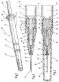
- Fig. 1 a single-use application device according to the invention is shown in perspective view and depicted in total with reference numeral 10.
- the application device 10 comprises a tubular receptacle 12 which is configured as a glass cylinder, having a first longitudinal end 13 and a second longitudinal end 14 and enclosing a cavity 15 that can be filled with a liquid.
- the cavity 15 is sealed to the outside by a piston 18 held at the end of a piston rod 20 and sealed against the interior wall of the cavity 15 by suitable sealing rings (not shown).
- the application device 10 is shown in Fig. 1 in its closed state in which the cavity 15 is sealed against a needle supported on the first tubular end 13 of the tubular receptacle 12 and surrounded by a collar 24 and an attached cap 22.
- the cap 22 For transferring the application device 10 from its closed state shown in Fig. 1 to an open state in which a liquid can be injected through the needle 32 shown in Fig. 2 and 3 , merely the cap 22 needs to be removed and thereafter the piston 22 can be advanced within the cavity 15 by pressing the end of the piston rod 20 with one finger while holding the tubular receptacle 12 at a gripping flange 16 provided on the second longitudinal end 14 with two fingers.
- the tubular receptacle 12 comprises a tubular extension 45 having a smaller diameter than the reminder of the tubular receptacle 12 and being connected to the reminder of the tubular receptacle 12 by a neck portion 44 defining a circumferential recess.
- a bung 46 held within the inner wall of the tubular extension 45 is a bung 46 made of a polypropylene material or from TPE.
- the bung is of generally cylindrical shape resting with a peripheral flange 50 against the end surface of the tubular extension 45 and having a central through channel 48 that opens into the cavity 15 at one end and opens into a delivery duct 36 of the needle 32 at the other end.
- Fig. 3 the bung 46 is shown in its released state so that the central through channel 48 is not blocked by a pinch seal effected in the closed state and shown in Fig. 2 .
- a holder 26 preferably made of a hard but elastic plastic material is attached onto the outer surface of the bung 46 and comprises an enlarged portion 40 having a larger outer diameter with a hollow tubular portion 41 that is fitted onto the peripheral flange 50 of the bung 46 and onto the tubular extension 45 of the tubular receptacle 12, thereby pressing the peripheral flange 50 of the bung 46 against the tubular extension of the receptacle 12.
- the enlarged portion 40 comprises an inner rim portion 42 at its end remote from the needle 32 engaging the neck portion 44 of the tubular receptacle 12.
- the collar 24 is pressed onto the peripheral wall of the enlarged portion 40 using a press fit and rests against a rim portion protruding outwardly at the end of the enlarged portion 40.
- the needle 32 usually made of stainless steel is fitted into a central opening 28 of the holder 26 and secured by an adhesive 30 or by another means so that the inner end of the needle 32 rests about flush with the through channel 48 of the bung 46.
- the holder 26 at one side comprises a flexible arm 34 extending from a portion near the inner end of the needle 32 and having a free end remote from the needle 32.
- the flexible arm 34 has a cross section of a wedged shape having a larger thickness at its free end than at its other end that is connected to the reminder of the holder 26.
- the holder 26 is made from a hard but elastic plastic material that allows to bias the flexible arm 34 into the position shown in Fig. 3 so that the bung 46 is not compressed in the open state indicated by numeral 10' in Fig. 3 .
- the cap 22 For transferring the application device into a closed state in which the central through channel 48 of the bung 46 is sealed by the pinch seal 52 as shown in Fig. 2 , the cap 22 needs to be attached on the holder 26.
- the cap 22 is inserted onto a peripheral portion of the holder 26 resting with its end within a slot provided between the peripheral portion of the holder 26 and the collar 24 and abutting against the enlarged portion 40 of the holder 26.
- the flexible arm 34 is pressed by the cap 22 to the inside against the bung 46 thereby effecting the pinch seal 52 of the through channel 48, whereby the through channel 48 is effectively blocked.
- This closed state shown in Fig. 2 is the ready-to-use state of the application device filled for instance with a medical drug by a drug manufacturer.
- the liquid containing the drug solution within cavity 15 is sealed against the needle 32 by the pinch seal 52.
- the cap 22 is pulled off from the holder 26 while holding the application device at the tubular receptacle 12.
- the flexible arm 34 flexes to the outside under its own bias thereby releasing the central through channel 48 so that the drug solution contained in cavity 15 may then ejected out of the needle tip 38 by advancing the piston rod 20 thereby expelling the drug solution through the needle tip 38.
- the inner wall surface of the bung may comprise a coating (not shown) that is made from a material that prevents sticking and that prevents interaction with any drug material.
- a coating may, e.g. consist of parylene or PTFE (polytretrafluorethylene).
Landscapes
- Health & Medical Sciences (AREA)
- Vascular Medicine (AREA)
- Engineering & Computer Science (AREA)
- Anesthesiology (AREA)
- Biomedical Technology (AREA)
- Heart & Thoracic Surgery (AREA)
- Hematology (AREA)
- Life Sciences & Earth Sciences (AREA)
- Animal Behavior & Ethology (AREA)
- General Health & Medical Sciences (AREA)
- Public Health (AREA)
- Veterinary Medicine (AREA)
- Infusion, Injection, And Reservoir Apparatuses (AREA)
- Coating Apparatus (AREA)
- Medical Preparation Storing Or Oral Administration Devices (AREA)
- Closures For Containers (AREA)
- Electrical Discharge Machining, Electrochemical Machining, And Combined Machining (AREA)
- Refuse Collection And Transfer (AREA)
- Seal Device For Vehicle (AREA)
Abstract
Description
- The invention relates to an application device for applying a dispensable material that is stored in a cavity of some kind of a receptacle. More particularly, the material may be a liquid, semi-liquid, pasty or powdered material preferably used for medical, diagnostic, cosmetic or dental applications. The application device comprises a closed state and an open state. It may be configured as an injection device configured for single or multiple use and having a closed state and an open state.
- From
US 2005/0212952 A1 an application device configured as a single-use syringe is known which comprises: - a tubular receptacle enclosing a cavity for receiving a liquid;
- a bung made of an elastic material being held at a first longitudinal end of the tubular receptacle and comprising a through channel that is fluidly connected with the cavity;
- a holder engaging the bung; and
- a needle secured within the holder and comprising a delivery duct fluidly connected with the through channel.
- The known syringe includes a tubular receptacle provided with sealingly closing-off elements delimiting a chamber, intended to be filled with a liquid, and having a liquid-delivery duct opening into the chamber, a needle-carrying base having a duct for supplying a liquid to the needle and being axially movable between a retracted position in which the delivery duct is closed-off, and an advanced injection position in which it allows the liquid to flow out of the chamber to the needle, a cap having a shape adapted to cover the base and provided with elements for detachable connection to the tubular receptacle, axial-stop elements arranged so as to keep the base in its closing-off position when the latter is covered by the cap, and axial stop elements arranged so as to limit the axial displacement travel of the base, once the cap is removed.
- The known device suffers from several draw-backs: First of all the opening and closing system of the syringe relies on clips made of hard plastic material that engage recesses provided on the holder. Reliability of the working of these clips is based on plastic molded parts and relative tolerances between these parts.
- Also the basic principle of this syringe for moving from the closed state to the open state is based on a sliding seal. There is the potential risk of a blocking of the seal after extended storage time. If the axial movement is impeded or blocked in some way, then there is the risk that the syringe may not be activated to allow an injection of the stored liquid to a patient.
- There is a variety of other so-called "dry needle" application devices, comprising a tubular receptacle containing the liquid to be injected and closed off by a membrane, and a double-point needle which can be displaced axially relative to the tubular receptacle so as to pierce the membrane at the moment of injection. (
DE 2 055 840 ;US 4,720,285 ;WO 96/013171 - The provision of a membrane seal poses a complication of the manufacturing process. In addition, there is always a necessary activation movement either by twisting of the cap or by an axial displacement of the part penetrating the membrane.
- Again, there is the risk of blocking of the penetrating needle so that the syringe may not be activated. Further there is the risk of generating particles as well.
- From
WO 2005/039669 A2 an application device according to the preamble of claim 1 is known. - The known device is a syringe that may be pre-filled and that may have a pinch seal for sealing the material contained within the cavity of the syringe as long as the cap is not removed.
- Although this application device leads to a considerable improvement over the prior art, it still suffers from some drawbacks.
- In view of this, it is an object of the invention to disclose an approved application device for applying a material stored within a cavity which is easy to manufacture and can be conveniently and reliably activated for use.
- Also, a method for manufacturing an application device that is pre-filled with a material to be applied shall be disclosed.
- This object is achieved by an application device according to claim 1 and by a method according to
claim 14. - The object is fully achieved in this way.
- A long-term sealing of a material obtained within the cavity of the receptacle is effected. While the cap may consist of a material that may be subject to creeping during long-term storage, such possible creeping is prevented by the collar that may consist of a more stable material.
- The sealing is effected in a very simple way. If possibly after extended storage time there should occur some sticking within the through channel so that the pinch seal is permanently blocked, it may be opened by exerting a pressure.
- Alternatively, or in addition, the internal surface of the through channel of the elastic said elastic part may comprise a coating made of a material preventing sticking of the internal surface and interaction with any dispensable material filled into the cavity of the receptacle. This coating may, e.g. be a parylene or PTFE coating.
- So there is no risk that the application device cannot be transferred into its open state even after extended storage life.
- According to a further feature of the invention the elastic part comprises a peripheral flange resting against an end portion of the receptacle, the peripheral flange being sealed against said end portion by the holder which at least partially encloses the peripheral flange and secures it to the end portion of the receptacle.
- Thus the application device includes an integrated sealing of the cavity of the receptacle with the delivery means or needle connected thereto.
- According to a preferred embodiment of the invention the receptacle is configured as a syringe barrel, cartridge, vial, bottle or bag.
- According to a further embodiment of the invention the dispensing means is configured as a needle or as a coupling, in particular as a Luer-Lock thread, for attaching a part.
- So the dispensing means may preferably be coupled to a needle so as to allow an injection of the material stored within the cavity into a patient or into an animal, or to allow a direction into any other part attached by some sort of coupling such as a Luer-Lock thread, a bayonet type connector etc.
- According to a further development of the invention the elastic part is configured as a bung at least partially received within the holder.
- This allows for a simple design and easy activation or deactivation of the pinch seal.
- According to a further embodiment of the invention the application device further comprises:
- a receptacle enclosing a cavity for receiving a dispensable material;
- a bung made of an elastic material being held at a first longitudinal end of the receptacle and comprising the through channel that is fluidly connected with the cavity;
- a holder engaging the bung; and
- a needle secured within the holder and comprising a delivery duct fluidly connected with the through channel.
- In this way the application device is configured as a syringe.
- According to a further development of the invention the application device further comprises:
- a removable cap supported on a peripheral portion of the holder when being in the closed state;
- wherein the cap, when being in the closed state, compresses the peripheral portion of the holder at least partially, thereby effecting the pinch seal; and
- wherein the pinch seal of the through channel is released, when the cap is removed, thereby allowing delivery of the dispensable material from the cavity through the through channel to the dispensing means, in particular through a delivery duct to a tip of a needle.
- Thus the application device may be configured as a ready-to-use prefilled injection syringe.
- According to this design the pinch seal can be effected in a very simple way by compressing the bung with the cap when resting on a peripheral portion of the holder so that the through channel extending through the bung is fully blocked. When the syringe shall be made ready for use, only the cap must be taken off, thereby transferring the syringe into the open state. Upon removal of the cap the pressure exerted by the cap on the bung is released so that the bung flexes outwardly under its own elastic force thereby freeing the through channel.
- In addition, since the pinch seal is merely effected by compressing the elastic bung by the cap being supported on a peripheral portion of the holder, the operation of the syringe is not influenced by any clip tolerances, and activation of the syringe can be effected very reliably.
- According to a further development of the invention the holder comprises at least one flexible arm that is pressed by the cap against the bung to generate a pinch seal of the through channel when being in the closed state.
- This feature allows a very effective sealing of the through channel, since the flexible arm allows to generate a high pressure on the bung so as to effect a good pinch seal.
- According to a further development of this design the at least one flexible arm is biased to the outside so as to release the pinch seal upon removal of the cap.
- In this way an easy release of the pinch seal is effected upon removal of the cap. So the flexible arm allows to generate an effective pinch seal when being in the closed state and to reliably transition into the open state under its own biasing force.
- Preferably the holder is made of a hard plastic material that generates a biasing force on the at least one flexible arm when pressed into the closed state.
- In this way no additional biasing means, such as a spring means, is necessary to effect the desired biasing force.
- The bung may preferably be made of a polypropylene, a thermo plastic elastomer (TPE), silicone rubber (LSR) or a different rubber type material.
- Such a material provides the desired resilience to effect a good pinch seal in the compressed state and to release the pinch seal upon release of the outer pressure. Also this material can easily be molded into the desired shape.
- According to a further development of the invention the tubular receptacle comprises a tubular extension being connected to the reminder of the tubular receptacle by a neck portion, wherein the holder comprises a hollow tubular portion that is mated to the tubular extension and comprises an inner rim portion protruding to the inside and engaging the neck portion for securing the holder on the tubular extension.
- This allows for a simple and reliable design.
- According to a further development of this design a collar is fitted onto the periphery of the hollow tubular portion for locking the inner rim portion onto the neck portion.
- This allows for a simple assembly and a reliable securement of the holder on the tubular extension of the tubular receptacle.
- According to a further development of the invention the bung comprises a peripheral flange being secured within the hollow tubular portion of the holder abutting the tubular extension of the receptacle.
- Thereby reliable design and safe seal is facilitated.
- The cap is preferably made from a rigid material, preferably from a hard plastic material.
- This design allows an easy manufacture by molding and, in addition, provides sufficient rigidity to effect the necessary pressure for the pinch seal when being seated on the peripheral part of the holder.
- According to a further development of the invention the cavity of the tubular receptacle is filled with a liquid which is sealed by a piston that is displaceable within the tubular receptacle by a piston rod.
- In this way the single-use application device is filled with the desired liquid that can be expelled from the tip in the usual manner by exerting pressure on the piston rod for advancing the piston within the tubular receptacle.
- According to a further embodiment of the invention the application device comprises a plurality of pinch seals coupled to different dispensable materials allowing a mixing of the materials after transfer of the pinch seals into the open state.
Thus a series of pinch seals may be used to seal of different dispensable materials and to effect a mixing of the materials when the pinch seals are transferred into the open state. - The object of the invention is further solved by a method according to
claim 14. - The holder may support an injection needle or some kind of coupling such as a Luer-Lock thread or a bayonet-type connection.
- Prior to filling the application device may be sterilized either in an assembled state or in a pre-assembled (open) state.
- It is understood that the features of the invention mentioned above and those yet to be explained below can be used not only in the respective combinations indicated, but also in other combinations or in isolation, without leaving the scope of the present invention.
- Other features and advantages of the invention will become apparent from a preferred embodiment of the invention which will be described hereafter with reference to the drawings which are of merely exemplary nature without limiting the scope of the invention and in which:
- Fig. 1
- shows a perspective view of an application device according to the invention;
- Fig. 2
- shows an enlarged longitudinal partial section of the application device according to
Fig. 1 in the region of the cap and the adjoining longitudinal end of the tubular receptacle, shown in the closed state with the cap attached; and - Fig. 3
- the application device of
Fig. 2 in its open state, after removal of the cap. - In
Fig. 1 a single-use application device according to the invention is shown in perspective view and depicted in total withreference numeral 10. - The
application device 10 comprises atubular receptacle 12 which is configured as a glass cylinder, having a firstlongitudinal end 13 and a secondlongitudinal end 14 and enclosing acavity 15 that can be filled with a liquid. Thecavity 15 is sealed to the outside by apiston 18 held at the end of apiston rod 20 and sealed against the interior wall of thecavity 15 by suitable sealing rings (not shown). - The
application device 10 is shown inFig. 1 in its closed state in which thecavity 15 is sealed against a needle supported on the firsttubular end 13 of thetubular receptacle 12 and surrounded by acollar 24 and an attachedcap 22. - For transferring the
application device 10 from its closed state shown inFig. 1 to an open state in which a liquid can be injected through theneedle 32 shown inFig. 2 and 3 , merely thecap 22 needs to be removed and thereafter thepiston 22 can be advanced within thecavity 15 by pressing the end of thepiston rod 20 with one finger while holding thetubular receptacle 12 at agripping flange 16 provided on the secondlongitudinal end 14 with two fingers. - The details of the application device that allow a sealing of the
cavity 15 against theneedle 32 when being in its closed (or "dry") state and for transferring the application device into its open state in which liquid stored within thecavity 15 can be injected through atip 38 of theneedle 32 will be explained hereinafter with reference toFigs. 2 and 3 . - According to
Fig. 2 thetubular receptacle 12 comprises atubular extension 45 having a smaller diameter than the reminder of thetubular receptacle 12 and being connected to the reminder of thetubular receptacle 12 by aneck portion 44 defining a circumferential recess. Held within the inner wall of thetubular extension 45 is a bung 46 made of a polypropylene material or from TPE. The bung is of generally cylindrical shape resting with aperipheral flange 50 against the end surface of thetubular extension 45 and having a central throughchannel 48 that opens into thecavity 15 at one end and opens into adelivery duct 36 of theneedle 32 at the other end. - In
Fig. 3 thebung 46 is shown in its released state so that the central throughchannel 48 is not blocked by a pinch seal effected in the closed state and shown inFig. 2 . Aholder 26 preferably made of a hard but elastic plastic material is attached onto the outer surface of the bung 46 and comprises anenlarged portion 40 having a larger outer diameter with ahollow tubular portion 41 that is fitted onto theperipheral flange 50 of the bung 46 and onto thetubular extension 45 of thetubular receptacle 12, thereby pressing theperipheral flange 50 of the bung 46 against the tubular extension of thereceptacle 12. To effect a proper securement, theenlarged portion 40 comprises aninner rim portion 42 at its end remote from theneedle 32 engaging theneck portion 44 of thetubular receptacle 12. To finally secure theholder 26 against removal from thetubular receptacle 12, in addition, thecollar 24 is pressed onto the peripheral wall of theenlarged portion 40 using a press fit and rests against a rim portion protruding outwardly at the end of theenlarged portion 40. - The
needle 32, usually made of stainless steel is fitted into acentral opening 28 of theholder 26 and secured by an adhesive 30 or by another means so that the inner end of theneedle 32 rests about flush with the throughchannel 48 of thebung 46. - The
holder 26 at one side comprises aflexible arm 34 extending from a portion near the inner end of theneedle 32 and having a free end remote from theneedle 32. Theflexible arm 34 has a cross section of a wedged shape having a larger thickness at its free end than at its other end that is connected to the reminder of theholder 26. Theholder 26 is made from a hard but elastic plastic material that allows to bias theflexible arm 34 into the position shown inFig. 3 so that the bung 46 is not compressed in the open state indicated by numeral 10' inFig. 3 . - For transferring the application device into a closed state in which the central through
channel 48 of the bung 46 is sealed by thepinch seal 52 as shown inFig. 2 , thecap 22 needs to be attached on theholder 26. Thecap 22 is inserted onto a peripheral portion of theholder 26 resting with its end within a slot provided between the peripheral portion of theholder 26 and thecollar 24 and abutting against theenlarged portion 40 of theholder 26. In this closed state shown inFig. 2 theflexible arm 34 is pressed by thecap 22 to the inside against the bung 46 thereby effecting thepinch seal 52 of the throughchannel 48, whereby the throughchannel 48 is effectively blocked. - This closed state shown in
Fig. 2 is the ready-to-use state of the application device filled for instance with a medical drug by a drug manufacturer. The liquid containing the drug solution withincavity 15 is sealed against theneedle 32 by thepinch seal 52. When the application device needs to be used, merely thecap 22 is pulled off from theholder 26 while holding the application device at thetubular receptacle 12. Once thecap 22 is removed, as shown inFig. 3 , theflexible arm 34 flexes to the outside under its own bias thereby releasing the central throughchannel 48 so that the drug solution contained incavity 15 may then ejected out of theneedle tip 38 by advancing thepiston rod 20 thereby expelling the drug solution through theneedle tip 38. - In case after a long storage period there should be some tendency of sticking between the two adjacent parts of the inner wall of the bung 46 effecting the
pinch seal 52, the pressure generated by advancing thepiston 18 into thecavity 15 will effectively remove any potential blockage of thepinch seal 52. - Alternatively, or in addition, the inner wall surface of the bung may comprise a coating (not shown) that is made from a material that prevents sticking and that prevents interaction with any drug material. Such a coating may, e.g. consist of parylene or PTFE (polytretrafluorethylene).
- This leads to a very reliable design.
Claims (15)
- An application device for applying a dispensable material, the application device (10) having a closed state and an open state and comprising:- an elastic part (46) made of an elastic material and having a through channel (48) being configured for engaging a cavity (15) of a receptacle (12);- a holder (26) comprising a support (28) for receiving a dispensing means (32) fluidly connected with said through channel (48); and- a pinch seal (52) sealing said through channel (48) when being in said closed state;- a removable cap (22) that is supported on a peripheral portion of the holder when being in the closed position; and- a collar (24) that is fitted onto an end portion (45) of said receptacle (12); wherein- said cap (22), when being in the closed state, compresses said peripheral portion of said holder (26) at least partially, thereby effecting said pinch seal (52);- said pinch seal (52) of said through channel (48) is released, when said cap (22) is removed, thereby allowing delivery of liquid from said cavity (15) through said through channel (48) to said dispensing means (32);characterized in that- said cap (22) comprises an end portion that at least partially fits into said collar (24).
- The application device of claim 1, characterized in that said elastic part (46) comprises a peripheral flange (50) resting against an end portion (45) of said receptacle (12), said peripheral flange (50) being sealed against said end portion (45) by said holder (26) which at least partially encloses said peripheral flange (50) and secures it to said end portion (45) of said receptacle (12).
- The application device of any of the preceding claims, characterized in that said elastic part (46) is configured as a bung at least partially received within said holder (26).
- The application device of any of the preceding claims, said application device (10) characterized by:- a tubular receptacle (12) enclosing said cavity (15) for receiving a liquid;- a bung (46) made of an elastic material being held at a first longitudinal end (13) of said tubular receptacle (12) and comprising said through channel (48) that is fluidly connected with said cavity (15); and- a needle secured (32) within said holder (26) and comprising a delivery duct (36) fluidly connected with said through channel (48); wherein- said holder (26) engages said bung (46).
- The application device of claim 4, characterized in that- said cap (22) is removable and supported on a peripheral portion of said holder (26) when being in said closed state;- said cap (22), when being in the closed state, compresses said peripheral portion of said holder (26) at least partially, thereby effecting said pinch seal (52); and- said pinch seal (52) of the through channel (48) is released, when said cap (22) is removed, thereby allowing delivery of liquid from said cavity (15) through said through channel (48) and said delivery duct (36) to a tip (38) of the needle (32).
- The application device of any of the preceding claims, characterized in that said holder (26) comprises at least one flexible arm (34) that is pressed against said flexible part (46) to generate said pinch seal (52) of said through channel (48) when being in said closed state, said at least one flexible arm (34) preferably being biased to the outside so as to release said pinch seal (52) upon removal of said cap (22).
- The application device of any of the preceding claims, characterized in that said holder (26) is made of a hard plastic material that generates a biasing force on said at least one flexible arm (34) when pressed into the closed state.
- The application device of any of claims 1 to 7, characterized in that said receptacle (12) is configured tubular comprising a tubular extension (45) being connected to the remainder of said receptacle (12) by a neck portion (44), and wherein said holder (26) comprises a hollow tubular portion (41) that is mated to said tubular extension (45) and comprises an inner rim portion (42) protruding to the inside and engaging said neck portion (44) for securing said holder (26) on said tubular extension (45).
- The application device of claim 8, characterized by a collar (54) that is fitted onto the periphery of said hollow tubular portion (41) for locking said inner rim portion (42) onto said neck portion (44).
- The application device of claim 8 or 9, characterized in that said bung (46) comprises a peripheral flange (50) being secured within said hollow tubular portion (41) of said holder (26) abutting said tubular extension (45) of said receptacle (12).
- The application device of any of any of the preceding claims, characterized in that said cavity (14) of said receptacle (12) is filled with a dispensable material which is sealed by a piston (18) that is displaceable within said receptacle (12) by a piston rod (20).
- The application device of any of the preceding claims, characterized by a plurality of pinch seals (52) coupled to different dispensable materials allowing a mixing of the materials after transfer of the pinch seals into the open state.
- The application device of any of the preceding claims, characterized in that said through channel (48) of said elastic part (46) comprises an internal surface that comprises a coating made of a material preventing sticking of the inner surface and interaction with any dispensable material filled into said cavity (15) of said receptacle (12), the coating preferably consisting of parylene or PTFE.
- A method of manufacturing an application device (10) having a closed state and an open state, the method comprising the following steps:- providing a receptacle (12) enclosing a cavity (15) for receiving a liquid;- attaching a bung (46) made of an elastic material to the receptacle (12) so that a through channel (48) extending through the bung (46) is fluidly connected with said cavity (15);- providing a holder (26) comprising a support for receiving a dispensing means (32) fluidly connected with said through channel (48);- attaching the holder (26) to the bung (46) so that the bung (46) is at least partially enclosed from the outside and that the dispensing means (32) is fluidly connected with said through channel (48);- fitting a collar (24) onto an end portion (45) of said receptacle (12);- providing a removable cap (22);- attaching the cap (22) onto a peripheral portion of said holder (26), thereby pressing at least a portion (34) of said holder (26) onto said bung (46), thereby generating a pinch seal (52) of said through channel (48); and- securing an end portion of said cap (22) within said collar (24).
- The method of claim 14, further comprising the step of sterilizing the application device prior to filling, either in an open state prior to assembling the application device, or after assembly prior to filling.
Priority Applications (1)
| Application Number | Priority Date | Filing Date | Title |
|---|---|---|---|
| EP08784847.9A EP2173416B1 (en) | 2007-07-25 | 2008-07-17 | Application device |
Applications Claiming Priority (3)
| Application Number | Priority Date | Filing Date | Title |
|---|---|---|---|
| EP07014576A EP2018885B1 (en) | 2007-07-25 | 2007-07-25 | Application device |
| PCT/EP2008/005867 WO2009012934A1 (en) | 2007-07-25 | 2008-07-17 | Application device |
| EP08784847.9A EP2173416B1 (en) | 2007-07-25 | 2008-07-17 | Application device |
Publications (2)
| Publication Number | Publication Date |
|---|---|
| EP2173416A1 EP2173416A1 (en) | 2010-04-14 |
| EP2173416B1 true EP2173416B1 (en) | 2016-03-23 |
Family
ID=38957701
Family Applications (2)
| Application Number | Title | Priority Date | Filing Date |
|---|---|---|---|
| EP07014576A Not-in-force EP2018885B1 (en) | 2007-07-25 | 2007-07-25 | Application device |
| EP08784847.9A Not-in-force EP2173416B1 (en) | 2007-07-25 | 2008-07-17 | Application device |
Family Applications Before (1)
| Application Number | Title | Priority Date | Filing Date |
|---|---|---|---|
| EP07014576A Not-in-force EP2018885B1 (en) | 2007-07-25 | 2007-07-25 | Application device |
Country Status (6)
| Country | Link |
|---|---|
| US (1) | US8657780B2 (en) |
| EP (2) | EP2018885B1 (en) |
| CN (1) | CN101801444B (en) |
| AT (1) | ATE497799T1 (en) |
| DE (1) | DE602007012427D1 (en) |
| WO (1) | WO2009012934A1 (en) |
Cited By (1)
| Publication number | Priority date | Publication date | Assignee | Title |
|---|---|---|---|---|
| EP4275721A1 (en) | 2022-05-11 | 2023-11-15 | Inductio AG | Medical syringe |
Families Citing this family (14)
| Publication number | Priority date | Publication date | Assignee | Title |
|---|---|---|---|---|
| DE102011110474A1 (en) | 2011-07-29 | 2013-01-31 | Fresenius Medical Care Deutschland Gmbh | Holding device for holding at least one hose clamp on a medical tube, medical tube and method for sterilizing a medical tube |
| US9022975B2 (en) * | 2012-09-12 | 2015-05-05 | Ethicon, Inc. | Airless, non-clogging tip assembly and device |
| WO2015140262A1 (en) * | 2014-03-21 | 2015-09-24 | Novo Nordisk A/S | Drug delivery device with cap induced needle movement |
| AU2014405591B2 (en) | 2014-09-04 | 2020-05-21 | Ethicon, Inc. | Minimally clogging device for delivery of fluids and method of use |
| EP3061479A1 (en) * | 2015-02-27 | 2016-08-31 | Sanofi-Aventis Deutschland GmbH | Sealed needle assembly for medicament delivery device |
| US9598183B1 (en) * | 2016-05-06 | 2017-03-21 | Kellstrom Defense Aerospace, Inc. | Aircraft wing repair systems and methods |
| CN107596509B (en) * | 2017-09-19 | 2022-07-08 | 李奇元 | Needle head device for safety syringe |
| WO2020216918A1 (en) | 2019-04-26 | 2020-10-29 | Becton Dickinson France | Needle cover with undercut |
| US11357588B1 (en) | 2019-11-25 | 2022-06-14 | Patrick Vitello | Needle packaging and disposal assembly |
| US12070591B1 (en) * | 2020-12-14 | 2024-08-27 | Patrick Vitello | Snap action tamper evident closure assembly |
| US11872187B1 (en) | 2020-12-28 | 2024-01-16 | Jonathan Vitello | Tamper evident seal for a vial cover |
| EP4059473A1 (en) * | 2021-03-16 | 2022-09-21 | medmix Switzerland AG | Dispenser and method of assembling a dispenser |
| US12172803B1 (en) | 2021-10-04 | 2024-12-24 | Patrick Vitello | Tamper evident integrated closure |
| US12545483B1 (en) | 2022-04-22 | 2026-02-10 | Medical Device Engineering, Llc | Systems and methods for filling and venting dropper bottles |
Family Cites Families (8)
| Publication number | Priority date | Publication date | Assignee | Title |
|---|---|---|---|---|
| US3638650A (en) * | 1970-04-29 | 1972-02-01 | Burron Medical Prod Inc | Syringe and needle adapter assembly and method of making same |
| DE2145962C3 (en) * | 1971-09-14 | 1980-10-02 | Societe Des Produits Nestle S.A., Vevey (Schweiz) | Injection syringe |
| JPS6030528A (en) | 1983-07-28 | 1985-02-16 | Toyo Kohan Co Ltd | Forming tool for metallic foil container excellent in drawing formability |
| CH667811A5 (en) * | 1984-11-21 | 1988-11-15 | Ewald Pickhard | INJECTION SYRINGE. |
| WO1996013171A1 (en) | 1994-10-29 | 1996-05-09 | Retep Foods Limited | Treatment and production of potato slices for preservation |
| FR2839892B1 (en) * | 2002-05-27 | 2005-03-18 | Mb Innovation | INJECTION DEVICE FOR SINGLE USE INTENDED FOR PRE-FILLING |
| WO2005039639A2 (en) | 2003-10-10 | 2005-05-06 | Solvay Pharmaceuticals Gmbh | Pharmaceutical composition comprising a selective i1 imidazoline receptor agonist and an angiotensin ii receptor blocker |
| EP1684822A2 (en) * | 2003-10-24 | 2006-08-02 | MDC Investment Holding, Inc. | Dual chamber mixing syringe and method for use |
-
2007
- 2007-07-25 AT AT07014576T patent/ATE497799T1/en not_active IP Right Cessation
- 2007-07-25 EP EP07014576A patent/EP2018885B1/en not_active Not-in-force
- 2007-07-25 DE DE602007012427T patent/DE602007012427D1/en active Active
-
2008
- 2008-07-17 CN CN200880100290XA patent/CN101801444B/en not_active Expired - Fee Related
- 2008-07-17 WO PCT/EP2008/005867 patent/WO2009012934A1/en not_active Ceased
- 2008-07-17 EP EP08784847.9A patent/EP2173416B1/en not_active Not-in-force
-
2010
- 2010-01-15 US US12/688,088 patent/US8657780B2/en not_active Expired - Fee Related
Cited By (2)
| Publication number | Priority date | Publication date | Assignee | Title |
|---|---|---|---|---|
| EP4275721A1 (en) | 2022-05-11 | 2023-11-15 | Inductio AG | Medical syringe |
| WO2023217973A1 (en) | 2022-05-11 | 2023-11-16 | Inductio Ag | Medical syringe |
Also Published As
| Publication number | Publication date |
|---|---|
| EP2018885A1 (en) | 2009-01-28 |
| ATE497799T1 (en) | 2011-02-15 |
| EP2018885B1 (en) | 2011-02-09 |
| WO2009012934A9 (en) | 2009-10-01 |
| CN101801444B (en) | 2013-06-26 |
| US20100211016A1 (en) | 2010-08-19 |
| CN101801444A (en) | 2010-08-11 |
| US8657780B2 (en) | 2014-02-25 |
| EP2173416A1 (en) | 2010-04-14 |
| DE602007012427D1 (en) | 2011-03-24 |
| WO2009012934A1 (en) | 2009-01-29 |
Similar Documents
| Publication | Publication Date | Title |
|---|---|---|
| US8657780B2 (en) | Application device | |
| CA2113953C (en) | Syringe needle isolation device | |
| US12161849B2 (en) | Injection device with outer cap with needle protection cap removal element and method for assembling an injection device | |
| JP7088825B2 (en) | Drug packaging | |
| CN105939742B (en) | Combined Cartridge and Needle Assembly | |
| CA2209956C (en) | Cannula sealing shield assembly | |
| JP4632510B2 (en) | Nose feeding device with spray nozzle | |
| US20120179109A1 (en) | Medical device | |
| CN101637627B (en) | Auto-disable device for syringes | |
| CN100558418C (en) | Disposable injection device that can be prefilled | |
| JP2009534152A (en) | Injection device with retractable needle | |
| JP2006501945A5 (en) | ||
| CN114521146A (en) | Needle system for drug injection | |
| CN112752613A (en) | Device for an aerosol dispenser, aerosol dispenser and method | |
| WO1997029798A1 (en) | Device | |
| KR20050067153A (en) | A fluid-handling device | |
| JP4050579B2 (en) | Prefilled syringe | |
| JP2004535254A (en) | Cartridge-free multiple dose injection device | |
| JP3558613B2 (en) | Syringe | |
| JP2006116223A (en) | Pre-filled syringe | |
| MXPA97005523A (en) | Can sealing protector assembly | |
| KR20230110492A (en) | Medical syringe with needle guard |
Legal Events
| Date | Code | Title | Description |
|---|---|---|---|
| PUAI | Public reference made under article 153(3) epc to a published international application that has entered the european phase |
Free format text: ORIGINAL CODE: 0009012 |
|
| 17P | Request for examination filed |
Effective date: 20100121 |
|
| AK | Designated contracting states |
Kind code of ref document: A1 Designated state(s): AT BE BG CH CY CZ DE DK EE ES FI FR GB GR HR HU IE IS IT LI LT LU LV MC MT NL NO PL PT RO SE SI SK TR |
|
| AX | Request for extension of the european patent |
Extension state: AL BA MK RS |
|
| RIN1 | Information on inventor provided before grant (corrected) |
Inventor name: PALMER-FELGATE, JOHN PAUL |
|
| DAX | Request for extension of the european patent (deleted) | ||
| RAP1 | Party data changed (applicant data changed or rights of an application transferred) |
Owner name: SCHOTT SCHWEIZ AG |
|
| 17Q | First examination report despatched |
Effective date: 20121005 |
|
| GRAP | Despatch of communication of intention to grant a patent |
Free format text: ORIGINAL CODE: EPIDOSNIGR1 |
|
| INTG | Intention to grant announced |
Effective date: 20151105 |
|
| GRAS | Grant fee paid |
Free format text: ORIGINAL CODE: EPIDOSNIGR3 |
|
| GRAA | (expected) grant |
Free format text: ORIGINAL CODE: 0009210 |
|
| AK | Designated contracting states |
Kind code of ref document: B1 Designated state(s): AT BE BG CH CY CZ DE DK EE ES FI FR GB GR HR HU IE IS IT LI LT LU LV MC MT NL NO PL PT RO SE SI SK TR |
|
| REG | Reference to a national code |
Ref country code: GB Ref legal event code: FG4D |
|
| REG | Reference to a national code |
Ref country code: CH Ref legal event code: NV Representative=s name: BOVARD AG, CH Ref country code: CH Ref legal event code: EP |
|
| REG | Reference to a national code |
Ref country code: AT Ref legal event code: REF Ref document number: 782520 Country of ref document: AT Kind code of ref document: T Effective date: 20160415 |
|
| REG | Reference to a national code |
Ref country code: IE Ref legal event code: FG4D |
|
| REG | Reference to a national code |
Ref country code: DE Ref legal event code: R096 Ref document number: 602008043072 Country of ref document: DE |
|
| REG | Reference to a national code |
Ref country code: FR Ref legal event code: PLFP Year of fee payment: 9 |
|
| REG | Reference to a national code |
Ref country code: LT Ref legal event code: MG4D |
|
| REG | Reference to a national code |
Ref country code: NL Ref legal event code: MP Effective date: 20160323 |
|
| PG25 | Lapsed in a contracting state [announced via postgrant information from national office to epo] |
Ref country code: NO Free format text: LAPSE BECAUSE OF FAILURE TO SUBMIT A TRANSLATION OF THE DESCRIPTION OR TO PAY THE FEE WITHIN THE PRESCRIBED TIME-LIMIT Effective date: 20160623 Ref country code: FI Free format text: LAPSE BECAUSE OF FAILURE TO SUBMIT A TRANSLATION OF THE DESCRIPTION OR TO PAY THE FEE WITHIN THE PRESCRIBED TIME-LIMIT Effective date: 20160323 Ref country code: GR Free format text: LAPSE BECAUSE OF FAILURE TO SUBMIT A TRANSLATION OF THE DESCRIPTION OR TO PAY THE FEE WITHIN THE PRESCRIBED TIME-LIMIT Effective date: 20160624 |
|
| REG | Reference to a national code |
Ref country code: AT Ref legal event code: MK05 Ref document number: 782520 Country of ref document: AT Kind code of ref document: T Effective date: 20160323 |
|
| PG25 | Lapsed in a contracting state [announced via postgrant information from national office to epo] |
Ref country code: LV Free format text: LAPSE BECAUSE OF FAILURE TO SUBMIT A TRANSLATION OF THE DESCRIPTION OR TO PAY THE FEE WITHIN THE PRESCRIBED TIME-LIMIT Effective date: 20160323 Ref country code: NL Free format text: LAPSE BECAUSE OF FAILURE TO SUBMIT A TRANSLATION OF THE DESCRIPTION OR TO PAY THE FEE WITHIN THE PRESCRIBED TIME-LIMIT Effective date: 20160323 Ref country code: LT Free format text: LAPSE BECAUSE OF FAILURE TO SUBMIT A TRANSLATION OF THE DESCRIPTION OR TO PAY THE FEE WITHIN THE PRESCRIBED TIME-LIMIT Effective date: 20160323 Ref country code: SE Free format text: LAPSE BECAUSE OF FAILURE TO SUBMIT A TRANSLATION OF THE DESCRIPTION OR TO PAY THE FEE WITHIN THE PRESCRIBED TIME-LIMIT Effective date: 20160323 |
|
| PG25 | Lapsed in a contracting state [announced via postgrant information from national office to epo] |
Ref country code: EE Free format text: LAPSE BECAUSE OF FAILURE TO SUBMIT A TRANSLATION OF THE DESCRIPTION OR TO PAY THE FEE WITHIN THE PRESCRIBED TIME-LIMIT Effective date: 20160323 Ref country code: PL Free format text: LAPSE BECAUSE OF FAILURE TO SUBMIT A TRANSLATION OF THE DESCRIPTION OR TO PAY THE FEE WITHIN THE PRESCRIBED TIME-LIMIT Effective date: 20160323 Ref country code: IS Free format text: LAPSE BECAUSE OF FAILURE TO SUBMIT A TRANSLATION OF THE DESCRIPTION OR TO PAY THE FEE WITHIN THE PRESCRIBED TIME-LIMIT Effective date: 20160723 |
|
| PG25 | Lapsed in a contracting state [announced via postgrant information from national office to epo] |
Ref country code: AT Free format text: LAPSE BECAUSE OF FAILURE TO SUBMIT A TRANSLATION OF THE DESCRIPTION OR TO PAY THE FEE WITHIN THE PRESCRIBED TIME-LIMIT Effective date: 20160323 Ref country code: PT Free format text: LAPSE BECAUSE OF FAILURE TO SUBMIT A TRANSLATION OF THE DESCRIPTION OR TO PAY THE FEE WITHIN THE PRESCRIBED TIME-LIMIT Effective date: 20160725 Ref country code: ES Free format text: LAPSE BECAUSE OF FAILURE TO SUBMIT A TRANSLATION OF THE DESCRIPTION OR TO PAY THE FEE WITHIN THE PRESCRIBED TIME-LIMIT Effective date: 20160323 Ref country code: CZ Free format text: LAPSE BECAUSE OF FAILURE TO SUBMIT A TRANSLATION OF THE DESCRIPTION OR TO PAY THE FEE WITHIN THE PRESCRIBED TIME-LIMIT Effective date: 20160323 Ref country code: SK Free format text: LAPSE BECAUSE OF FAILURE TO SUBMIT A TRANSLATION OF THE DESCRIPTION OR TO PAY THE FEE WITHIN THE PRESCRIBED TIME-LIMIT Effective date: 20160323 Ref country code: RO Free format text: LAPSE BECAUSE OF FAILURE TO SUBMIT A TRANSLATION OF THE DESCRIPTION OR TO PAY THE FEE WITHIN THE PRESCRIBED TIME-LIMIT Effective date: 20160323 |
|
| PG25 | Lapsed in a contracting state [announced via postgrant information from national office to epo] |
Ref country code: BE Free format text: LAPSE BECAUSE OF FAILURE TO SUBMIT A TRANSLATION OF THE DESCRIPTION OR TO PAY THE FEE WITHIN THE PRESCRIBED TIME-LIMIT Effective date: 20160323 |
|
| REG | Reference to a national code |
Ref country code: DE Ref legal event code: R097 Ref document number: 602008043072 Country of ref document: DE |
|
| PLBE | No opposition filed within time limit |
Free format text: ORIGINAL CODE: 0009261 |
|
| STAA | Information on the status of an ep patent application or granted ep patent |
Free format text: STATUS: NO OPPOSITION FILED WITHIN TIME LIMIT |
|
| PG25 | Lapsed in a contracting state [announced via postgrant information from national office to epo] |
Ref country code: DK Free format text: LAPSE BECAUSE OF FAILURE TO SUBMIT A TRANSLATION OF THE DESCRIPTION OR TO PAY THE FEE WITHIN THE PRESCRIBED TIME-LIMIT Effective date: 20160323 |
|
| PG25 | Lapsed in a contracting state [announced via postgrant information from national office to epo] |
Ref country code: BG Free format text: LAPSE BECAUSE OF FAILURE TO SUBMIT A TRANSLATION OF THE DESCRIPTION OR TO PAY THE FEE WITHIN THE PRESCRIBED TIME-LIMIT Effective date: 20160623 |
|
| 26N | No opposition filed |
Effective date: 20170102 |
|
| GBPC | Gb: european patent ceased through non-payment of renewal fee |
Effective date: 20160717 |
|
| PG25 | Lapsed in a contracting state [announced via postgrant information from national office to epo] |
Ref country code: MC Free format text: LAPSE BECAUSE OF FAILURE TO SUBMIT A TRANSLATION OF THE DESCRIPTION OR TO PAY THE FEE WITHIN THE PRESCRIBED TIME-LIMIT Effective date: 20160323 |
|
| REG | Reference to a national code |
Ref country code: IE Ref legal event code: MM4A |
|
| PG25 | Lapsed in a contracting state [announced via postgrant information from national office to epo] |
Ref country code: GB Free format text: LAPSE BECAUSE OF NON-PAYMENT OF DUE FEES Effective date: 20160717 Ref country code: SI Free format text: LAPSE BECAUSE OF FAILURE TO SUBMIT A TRANSLATION OF THE DESCRIPTION OR TO PAY THE FEE WITHIN THE PRESCRIBED TIME-LIMIT Effective date: 20160323 |
|
| REG | Reference to a national code |
Ref country code: FR Ref legal event code: PLFP Year of fee payment: 10 |
|
| PG25 | Lapsed in a contracting state [announced via postgrant information from national office to epo] |
Ref country code: IE Free format text: LAPSE BECAUSE OF NON-PAYMENT OF DUE FEES Effective date: 20160717 |
|
| PG25 | Lapsed in a contracting state [announced via postgrant information from national office to epo] |
Ref country code: LU Free format text: LAPSE BECAUSE OF NON-PAYMENT OF DUE FEES Effective date: 20160717 |
|
| PG25 | Lapsed in a contracting state [announced via postgrant information from national office to epo] |
Ref country code: CY Free format text: LAPSE BECAUSE OF FAILURE TO SUBMIT A TRANSLATION OF THE DESCRIPTION OR TO PAY THE FEE WITHIN THE PRESCRIBED TIME-LIMIT Effective date: 20160323 Ref country code: HU Free format text: LAPSE BECAUSE OF FAILURE TO SUBMIT A TRANSLATION OF THE DESCRIPTION OR TO PAY THE FEE WITHIN THE PRESCRIBED TIME-LIMIT; INVALID AB INITIO Effective date: 20080717 |
|
| PG25 | Lapsed in a contracting state [announced via postgrant information from national office to epo] |
Ref country code: TR Free format text: LAPSE BECAUSE OF FAILURE TO SUBMIT A TRANSLATION OF THE DESCRIPTION OR TO PAY THE FEE WITHIN THE PRESCRIBED TIME-LIMIT Effective date: 20160323 Ref country code: MT Free format text: LAPSE BECAUSE OF NON-PAYMENT OF DUE FEES Effective date: 20160731 Ref country code: HR Free format text: LAPSE BECAUSE OF FAILURE TO SUBMIT A TRANSLATION OF THE DESCRIPTION OR TO PAY THE FEE WITHIN THE PRESCRIBED TIME-LIMIT Effective date: 20160323 |
|
| REG | Reference to a national code |
Ref country code: FR Ref legal event code: PLFP Year of fee payment: 11 |
|
| PGFP | Annual fee paid to national office [announced via postgrant information from national office to epo] |
Ref country code: IT Payment date: 20190730 Year of fee payment: 12 |
|
| PGFP | Annual fee paid to national office [announced via postgrant information from national office to epo] |
Ref country code: DE Payment date: 20200721 Year of fee payment: 13 Ref country code: FR Payment date: 20200723 Year of fee payment: 13 |
|
| PGFP | Annual fee paid to national office [announced via postgrant information from national office to epo] |
Ref country code: CH Payment date: 20200721 Year of fee payment: 13 |
|
| PG25 | Lapsed in a contracting state [announced via postgrant information from national office to epo] |
Ref country code: IT Free format text: LAPSE BECAUSE OF NON-PAYMENT OF DUE FEES Effective date: 20200717 |
|
| REG | Reference to a national code |
Ref country code: DE Ref legal event code: R119 Ref document number: 602008043072 Country of ref document: DE |
|
| REG | Reference to a national code |
Ref country code: CH Ref legal event code: PL |
|
| PG25 | Lapsed in a contracting state [announced via postgrant information from national office to epo] |
Ref country code: LI Free format text: LAPSE BECAUSE OF NON-PAYMENT OF DUE FEES Effective date: 20210731 Ref country code: DE Free format text: LAPSE BECAUSE OF NON-PAYMENT OF DUE FEES Effective date: 20220201 Ref country code: CH Free format text: LAPSE BECAUSE OF NON-PAYMENT OF DUE FEES Effective date: 20210731 |
|
| PG25 | Lapsed in a contracting state [announced via postgrant information from national office to epo] |
Ref country code: FR Free format text: LAPSE BECAUSE OF NON-PAYMENT OF DUE FEES Effective date: 20210731 |