EP2172948A1 - Magnetic element, and antenna device using the magnetic element - Google Patents
Magnetic element, and antenna device using the magnetic element Download PDFInfo
- Publication number
- EP2172948A1 EP2172948A1 EP08777411A EP08777411A EP2172948A1 EP 2172948 A1 EP2172948 A1 EP 2172948A1 EP 08777411 A EP08777411 A EP 08777411A EP 08777411 A EP08777411 A EP 08777411A EP 2172948 A1 EP2172948 A1 EP 2172948A1
- Authority
- EP
- European Patent Office
- Prior art keywords
- core
- magnetic element
- end surface
- recess
- protrusion
- Prior art date
- Legal status (The legal status is an assumption and is not a legal conclusion. Google has not performed a legal analysis and makes no representation as to the accuracy of the status listed.)
- Withdrawn
Links
Images


Classifications
-
- H—ELECTRICITY
- H01—ELECTRIC ELEMENTS
- H01Q—ANTENNAS, i.e. RADIO AERIALS
- H01Q7/00—Loop antennas with a substantially uniform current distribution around the loop and having a directional radiation pattern in a plane perpendicular to the plane of the loop
- H01Q7/06—Loop antennas with a substantially uniform current distribution around the loop and having a directional radiation pattern in a plane perpendicular to the plane of the loop with core of ferromagnetic material
-
- H—ELECTRICITY
- H01—ELECTRIC ELEMENTS
- H01F—MAGNETS; INDUCTANCES; TRANSFORMERS; SELECTION OF MATERIALS FOR THEIR MAGNETIC PROPERTIES
- H01F17/00—Fixed inductances of the signal type
- H01F17/04—Fixed inductances of the signal type with magnetic core
- H01F17/045—Fixed inductances of the signal type with magnetic core with core of cylindric geometry and coil wound along its longitudinal axis, i.e. rod or drum core
-
- H—ELECTRICITY
- H01—ELECTRIC ELEMENTS
- H01Q—ANTENNAS, i.e. RADIO AERIALS
- H01Q7/00—Loop antennas with a substantially uniform current distribution around the loop and having a directional radiation pattern in a plane perpendicular to the plane of the loop
- H01Q7/06—Loop antennas with a substantially uniform current distribution around the loop and having a directional radiation pattern in a plane perpendicular to the plane of the loop with core of ferromagnetic material
- H01Q7/08—Ferrite rod or like elongated core
-
- H—ELECTRICITY
- H01—ELECTRIC ELEMENTS
- H01F—MAGNETS; INDUCTANCES; TRANSFORMERS; SELECTION OF MATERIALS FOR THEIR MAGNETIC PROPERTIES
- H01F27/00—Details of transformers or inductances, in general
- H01F27/06—Mounting, supporting or suspending transformers, reactors or choke coils not being of the signal type
- H01F2027/065—Mounting on printed circuit boards
-
- H—ELECTRICITY
- H01—ELECTRIC ELEMENTS
- H01F—MAGNETS; INDUCTANCES; TRANSFORMERS; SELECTION OF MATERIALS FOR THEIR MAGNETIC PROPERTIES
- H01F27/00—Details of transformers or inductances, in general
- H01F27/24—Magnetic cores
- H01F27/26—Fastening parts of the core together; Fastening or mounting the core on casing or support
- H01F27/266—Fastening or mounting the core on casing or support
-
- H—ELECTRICITY
- H01—ELECTRIC ELEMENTS
- H01F—MAGNETS; INDUCTANCES; TRANSFORMERS; SELECTION OF MATERIALS FOR THEIR MAGNETIC PROPERTIES
- H01F5/00—Coils
- H01F5/04—Arrangements of electric connections to coils, e.g. leads
Definitions
- the present invention relates to a magnetic element including a core made of a magnetic material and a resin base fixed to the core, and to an antenna device using the magnetic element.
- Patent Document 1 there is known an inductance element including a core made of a magnetic material and a resin base fixed to the core (see, for example, Patent Document 1).
- the inductance element described in Patent Document 1 includes a first core and a second core each made of a magnetic material and resin bases fixed to the first core at both ends thereof. In addition, the bases are fixed to the first core with adhesive.
- Patent Document 1 JP H02-150004 A
- the bases are fixed to the core with an adhesive.
- insert molding may be used for fixing the resin base to the core.
- an object of the present invention is to provide a magnetic element capable of enhancing the fixing strength of the base with respect to the core even if the base is fixed to the core by the insert molding, and to provide an antenna device using the magnetic element.
- a magnetic element according to the present invention includes a core made of a magnetic material and a resin base that is formed by insert molding so as to be fixed to at least one of end portions of the core, in which the base is provided with a recess or a protrusion formed on an end surface of the one of end portions of the core.
- a recess is formed in at least one end surface of a core to which a base is fixed, so as to be recessed inward from an end surface. For this reason, when the base is formed by insert molding, a resin is led into the recess. Therefore, the contact area between the base and the core is increased to the extent that the recess is formed so that the contact resistance between the base and the core can be increased.
- a protrusion is formed on at least one end surface of the core. For this reason, when the base is formed by the insert molding, the resin is not formed at an engaging portion with the protrusion of the core.
- the contact area between the base and the core is increased to the extent that the protrusion of the core is formed so that the contact resistance between the base and the core can be increased.
- the fixing strength of the base with respect to the core can be enhanced even if the base is fixed to the core by the insert molding.
- an inner surface of the recess or an outer surface of the protrusion be formed so as to be parallel to the center axis of the core.
- the recess have a circular shape when the end surface of the core is viewed from the axial direction.
- the recess can be formed more easily compared with the case where a shape of the end surface of the core viewed from the axial direction is a polygonal shape.
- the recess have a polygonal shape when the end surface of the core is viewed from the axial direction.
- a positional shift of the base can be prevented by preventing rotation of the core in the circumferential direction compared with the case where a shape of the end surface of the core viewed from the axial direction is a circular shape.
- the protrusion have a circular shape when the end surface of the core is viewed from the axial direction.
- the protrusion can be formed more easily compared with the case where a shape of the end surface of the core viewed from the axial direction is a polygonal shape.
- a shape of the end surface of the core viewed from the axial direction be a polygonal shape.
- the protrusion can prevent rotation of the core in the circumferential direction and can prevent a positional shift of the base compared with the case where the shape of the end surface of the core viewed from the axial direction is a circular shape.
- the center axis of the cross-section of the recess or the protrusion be shifted from the center axis of the core.
- a center of rotation radius of the core does not agree with a center of rotation radius of the substantially circular or polygonal recess or protrusion. Therefore, a rotation action of the core itself in the circumferential direction does not correspond to a rotation action of the recess or the protrusion, and hence the fixing strength can be enhanced.
- the recess be formed like a groove in a radial direction of the end surface of the core, and the protrusion is formed linearly on the end surface of the core.
- the recess has a cross-section of a shape other than a perfect circle, the cross-section being parallel to the end surface of the core.
- a length of a part of the recess that is recessed inward from the end surface of the core to which the base is fixed be shorter than a length of the base from an end surface on the a side that is fixed to the core to a part of the recess that contacts with the end surface.
- a length from a tip of the protrusion to the end surface of the core be shorter than a length from an end surface of the base on a side that is fixed to the core to a part that comes in contact with the tip of the protrusion.
- a cross-sectional area of the recess in the present invention, it is preferred that a cross-sectional area of the recess, the cross-sectional area being parallel to the end surface of the core, increase gradually toward a depth direction of the recess.
- a cross-sectional area of the protrusion in the present invention, it is preferred that a cross-sectional area of the protrusion, the cross-sectional area being parallel to the end surface of the core, increase gradually toward a tip direction of the protrusion.
- an antenna device using any one of the above-mentioned magnetic elements.
- the fixing strength of the base with respect to the core can be enhanced even if the base is fixed to the core by insert molding.
- Embodiment 1 a magnetic element 1 according to Embodiment 1 is described with reference to FIGS. 1 to 5 .
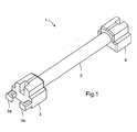
- FIG. 1 is a perspective view illustrating the magnetic element 1 according to the embodiment of the present invention.
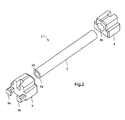
- FIG. 2 is an exploded perspective view of the magnetic element 1 illustrated in FIG. 1 .
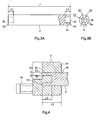
- FIGS. 3 are diagrams illustrating a core 2 illustrated in FIG. 1 , in which (A) illustrates the core 2 viewed from a direction perpendicular to an axial direction while (B) illustrates the core 2 viewed from the axial direction.
- FIG. 4 is a cross-sectional view of a fixing part of a base 3 with respect to the core 2 illustrated in FIG. 1 .
- the magnetic element 1 of this embodiment is used for an electronic component or an electronic device such as an antenna device constituting an electronic key system of an automobile or an IC tag.
- the magnetic element 1 includes the core 2 made of a magnetic material, bases 3 and 4 fixed to end portions of the core 2, and conductor wire (not shown) wound around an outer periphery of the core 2, as illustrated in FIG. 1 .
- the core 2 is made of a magnetic material as described above.
- the core 2 is made of a magnetic material such as Mn-Zn ferrite or Ni-Zn ferrite.
- the core 2 is formed to have a linear elongated rod-like shape.
- the core 2 is formed to have a cylindrical (or substantially cylindrical) shape.
- the core 2 is provided with a recess 2b that is recessed inward from an end surface 2a as illustrated in FIG. 3 .
- the core 2 is provided with the recess 2b like a round hole having a bottom formed radially inward of the core 2.
- a cross-section parallel to the end surface 2a of the recess 2b (cross-section perpendicular to the axial direction of the core 2) is formed to have a circular shape (or substantially circular shape) having a constant diameter.
- the recess 2b is formed to have a circular shape (or substantially circular shape) when viewed from the axial direction.
- the recess 2b is formed in the end surface 2a of each end portion of the core 2.
- the bases 3 and 4 are made of non-magnetic and insulative resin and are formed to have a block shape.
- the base 3 is fixed to one end portion of the core 2 and the base 4 is fixed to the other end portion of the core 2.
- the bases 3 and 4 are fixed to the end portions of the core 2 so that mounting surfaces with respect to a mounting substrate or the like to which the magnetic element 1 is mounted become parallel to each other (surface corresponding to the backside of the paper of FIG. 1 , or lower side of FIG. 4 ).
- the bases 3 and 4 are fixed to the end portions of the core 2 so that the bases 3 and 4 cover the end surfaces 2a and the outer peripheral surfaces of the core 2 at the end portions.
- the base 3 arranged at one end is provided with two terminal portions 3a to which end portions of the conductor wire wound around the core 2 are fixed by being wound around the same.
- the terminal portions 3a are formed so as to protrude outward in the axial direction of the core 2.
- the base 4 is formed similarly to the base 3 except for provision of the terminal portions 3a.
- the bases 3 and 4 are formed integrally with the core 2 by insert molding.
- the bases 3 and 4 are provided with arrangement holes 3b and 4b to which the end portions of the core 2 are arranged.
- a resin that forms the bases 3 and 4 is led and filled in the recess 2b as illustrated in FIG. 4 .
- the bases 3 and 4 are formed integrally with the core 2 by insert molding so that flatness of the mounting surfaces of the bases 3 and 4 can be enhanced.
- the conductor wire (not shown) wound around the outer periphery of the core 2 is obtained by covering the surface of the conductive wire material with an insulating coating.
- Each of the end portions of the conductor wire is wound around the terminal portion 3a of the base 3 so as to be fixed.
- the end portion of the wound conductor wire is soldered so that each of the end portions of the conductor wire is fixed to the terminal portion 3a.
- the magnetic element 1 having the structure described above is manufactured as follows.
- an original body of the core 2 is formed from powder of magnetic material such as ferrite by a press using a molding die.
- the original body of the core 2 is formed by powder press molding.
- the original body of the core 2 is subjected to cutting so that the core 2 is formed.
- the end surfaces 2a of both end portions are formed, and the recesses 2b are formed so as to be recessed inward from the end surfaces 2a, by cutting.
- the core 2 is completed by this cutting.
- the bases 3 and 4 are formed integrally with the core 2 by the insert molding in which the both end portions of the core 2 are arranged in the die for performing resin molding.
- the both end portions of the core 2 are placed in the die, resin is filled in the die, and the resin in the die is stiffened.
- the bases 3 and 4 illustrated in FIG. 2 and the like are formed by this insert molding.
- the resin that forms the bases 3 and 4 is filled in the recesses 2b of the core 2.
- one end of the conductor wire is wound around one terminal portion 3a and is bound.
- the conductor wire is wound around the outer periphery of the core 2.
- the other end portion of the conductor wire is wound around the other terminal portion 3a and is bound.
- the end portions of the conductor wire wound around the terminal portions 3a are soldered so that the magnetic element 1 is completed.
- the core 2 is provided with the recesses 2b that are formed to be recessed inward from the end surface 2a. Therefore, when the bases 3 and 4 are formed by the insert molding, the resin is led and filled in the recess 2b. Therefore, in addition to the end surfaces 2a of the core 2 and the outer peripheral surfaces at the end portions of the core 2, the inner walls of the recesses 2b contact with the resin that forms the bases 3 and 4. In other words, the contact area between each of the bases 3,4 and the core 2 can be increased, and hence the contact resistance between each of the bases 3,4 and the core 2 can be increased. As a result, in this embodiment, even if the bases 3 and 4 are fixed to the core 2 by the insert molding, the fixing strength of the bases 3 and 4 with respect to the core 2 can be enhanced.
- FIG. 5 illustrates experimental data showing the effect of the magnetic element 1 according to the embodiment of the present invention.
- a core which has the same total length L1 and the same outer diameter D1 as the core 2 and is not provided with the recess 2b (this core is referred to as "core 52" for convenience sake) was measured regarding the strength against detachment of the bases 3 and 4 (fixing strength of the core 52 in the axial direction). In this measurement too, twenty samples were used. The results are shown in the column of "COMPARISON REFERENCE” in FIG. 5 . Note that material of the cores 2 and 52 used in this experiment is manganese ferrite, and material of the bases 3 and 4 is liquid crystal polymer.
- an average value of the strength against detachment of the bases 3 and 4 with respect to the core 2 was 13.31 N (Newton), a maximum value of the same was 15.6 N, and a minimum value of the same was 12 N.
- the average value of the strength against detachment of the bases 3 and 4 with respect to the core 52 was 6.91 N, the maximum value was 9.2 N, and the minimum value was 4.4 N.
- the strength against detachment of the bases 3 and 4 with respect to the core 2 was much higher than the strength against detachment of the bases 3 and 4 with respect to the core 52.
- the average value of the strength against detachment of the bases 3 and 4 with respect to the core 2 was 1.9 times the average value of the strength against detachment of the bases 3 and 4 with respect to the core 52.
- the strength against detachment of the bases 3 and 4 with respect to the core 2 can be increased substantially.
- the contact area between each of the bases 3,4 and the core 2 can be increased, and hence the fixing strength of the bases 3 and 4 with respect to the core 2 in the circumferential direction of the core 2 can also be increased.
- the fixing strength of the bases 3 and 4 with respect to the core 2 can be increased even if the bases 3 and 4 are fixed to the core 2 by the insert molding.
- the recesses 2b are formed to have a circular shape when viewed from the axial direction. Therefore, for example, compared with the case where the recesses 2b are formed to have a polygonal shape viewed from the axial direction, the core 2 can be formed accurately, and the recesses 2b can be formed easily. In other words, if the recesses 2b are formed to have a polygonal shape when viewed from the axial direction, it is necessary to form the recesses 2b by the powder press molding, and hence it is difficult to increase accuracy of the core 2 in the longitudinal direction because the core 2 is formed only by the powder press molding.
- the recess 2b is formed to have a circular shape when viewed from the axial direction, accuracy of the core 2 in the longitudinal direction can be increased by the cutting after the powder press molding, and the recess 2b can be formed easily.
- the core 2 is formed to have a cylindrical shape. For this reason, compared with the case where the core 2 is formed to have a polygonal column shape, warping of the core 2 after the powder press molding can be suppressed so that the core 2 can be formed accurately.
- the fixing strength of the bases 3 and 4 with respect to the core 2 in the circumferential direction of the core 2 can be increased as described above. Therefore, even in this case, it is not necessary to provide an additional structure for stopping rotation of the bases 3 and 4 with respect to the core 2 so that the structure of the magnetic element 1 can be simplified.
- the inner surfaces of the recesses 2b are formed in parallel to the center axis of the core 2 in the axial direction. This facilitates grinding and coding of the core 2 after the powder press molding so that constant quality can be secured easily, compared with the case where the inner surfaces of the recesses 2b are formed not in parallel to the center axis of the core 2 but in a manner of crossing the same so as to form an inclined surface.
- the length (L2) of the portion recessed inward from the end surface 2a of the core 2 is shorter than the length (L3) from the end surface 3c of the base 3 facing the core 2 to the end surface 2a.
- This is for the purpose of avoiding a decrease in the fixing strength of the core 2 when a stress is exerted on the core 2 in the case where a position of the bottom surface of the recess 2b corresponds to a position of the end surface 3c of the base 3 on the side to be fixed to the core 2 (in the case where the lengths L2 and L3 correspond to each other) and in the case where L2 is longer than L3.
- the end surfaces 2a of the both end portions are formed and the recesses 2b that are recessed inward from the end surfaces 2a are also formed by the cutting after the powder press molding.
- the recesses 2b that are recessed inward from the end surfaces 2a may be formed in the original body of the core 2 by the powder press molding.
- the recesses 2b are formed to have a circular shape when viewed from the axial direction, and hence the die for the powder press molding can be simplified compared with the case where the recesses 2b are formed to have a polygonal shape when viewed from the axial direction.
- the recesses 2b are formed so as to have a circular shape when the end surfaces 2a are viewed from the axial direction.
- recesses 2d having a D-shape as a shape other than a perfect circle when the end surfaces 2a are viewed from the axial direction may be formed in the end surfaces 2a of the core 2 like another Embodiment 2 illustrated in FIG. 6(A) .
- recesses 2e having a rectangular shape when viewed from the axial direction may be formed in the end surfaces 2a of the core 2 like another Embodiment 2 illustrated in FIG. 6(B) .
- recesses having a polygonal shape such as a triangular shape and a pentagonal shape
- recesses 2f having a linear and grooved shape may be formed in the end surfaces 2a of the core 2 like another Embodiment 3 illustrated in FIGS. 7 . If the structures illustrated in FIGS. 6 and 7 are adapted, the contact resistance between each of the bases 3, 4 and the core 2 can be increased. In addition, rotation of the core 2 illustrated in FIGS. 6 and 7 in the circumferential direction can be prevented, and hence the positional shift of the bases 3 and 4 can be prevented. As a result, according to the structures illustrated in FIGS. 6 and 7 , the fixing strength of the bases 3 and 4 with respect to the core 2 in the circumferential direction can be enhanced even if the bases 3 and 4 are fixed to the core 2 by the insert molding.
- the center axis X1 or X2 of the recesses 2d or 2e described above may be formed in the core 2 so as to be shifted from the center axis X3 of the core 2.
- the fixing strength of the core 2 with respect to the bases 3 and 4 in the circumferential direction can be increased largely, and hence rotation restriction of the core 2 with respect to the bases 3 and 4 can be secured.
- the recesses 2d, 2e and 2f have a shape with the inner surface or the outer surface that is parallel to the axial direction.
- the recesses 2g formed in the tapered cylinder shape may be modified to have a tapered polygonal column shape.
- the core 2 is provided with the recesses 2b that are formed to be recessed from the end surfaces 2a inward in the radial direction of the core 2.
- protrusions 2h may be formed on the end surfaces 2a of the core 2 so that only the tips of the core 2 are protruded.
- the outer surfaces of the protrusions 2h should be formed to be parallel to the center axis of the core 2.
- the cross-sectional area of the protrusion 2i that is parallel to the end surface 2a of the core 2 may be formed to increase gradually toward the tip of the protrusion 2i. If the structure illustrated in FIG. 11(B) is adopted, the core 2 is hardly detached from the bases 3 and 4. Thus, detachment of the core can be prevented.
- a length (L4) of the protrusion 2h from the tip 2ha of the protruding portion to the end surface 2a should be shorter than a length (L5) of the base 3 from the end surface 3c facing the core 2 to the protrusion 2h. This is for the purpose of avoiding a decrease in the fixing strength of the core 2 when a stress is exerted on the core 2 in the case where a position of the bottom surface of the protrusion 2h corresponds to a position of the end surface 3c of the base 3 on the side to be fixed to the core 2 (in the case where the lengths L4 and L5 correspond to each other) and in the case where L4 is longer than L5.
- D-shape protrusions 2k or rectangular shape protrusions 2m may be adopted similarly to the recesses 2d or 2e described above.
- the center axes of the protrusions 2k and 2m are the same as the center axis X3 of the core 2.
- the center axis X3 of the protrusions 2j, 2k or 2m may be shifted from the center axis of the core 2 (not shown). Even in this case, the contact area between each of the bases 3 and 4 and the core 2 can be increased so that the fixing strength of the bases 3 and 4 with respect to the core 2 can be enhanced.
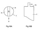
- protrusions 2n may be formed so as to cross the core 2 sectionally or longitudinally with respect to the radial direction viewed from the axial direction.
- the protrusion 2n is viewed from the g-direction as illustrated in FIG. 16(B) , the protrusion 2n is formed from one end of the outer periphery to the other end of the outer periphery. Even in this structure, the contact area between each of the bases 3,4 and core 2 can be increased so that the fixing strength of the bases 3 and 4 with respect to the core 2 can be enhanced.
- the core 2 is formed to have a cylindrical shape.
- the core 2 may be formed to have a polygonal column shape such as a rectangular column shape or a pentagonal column shape.
- the core 2 may be formed to have an elliptic cylinder shape.
- the center axis X3 of the core 2 and the center axis of the recess or the protrusion are the same or parallel to each other, but the center axes may be neither the same nor parallel to each other.
- the bases 3 and 4 are fixed to both ends of the core 2.
- the base 3 or 4 may be fixed to only one end or to the other end of the core 2.
- the recess 2b may be formed only in the end surface 2a on the side to which the base 3 or 4 is fixed, or the recess 2b may be formed in each end surface 2a of both sides of the core 2.
- the example having one core 2 and two bases 3,4, as well as the example having one core 2 and one base 3 or having one core 2 and one base 4 is described, but it is possible to adopt the magnetic element including two cores 2 and one base 3, the magnetic element including two cores 2 and two bases 3,4, or the magnetic element including one core 2 and three bases.
- the base 3 is provided with the two terminal portions 3a, but it is possible that each of the bases 3 and 4 is provided with one terminal portion.
- a metal terminal is formed integrally with the base 3 and/or base 4.
- the magnetic element described above includes the conductor wire, but the magnetic element may be one in the state without the conductor wire.
- a contour line of the inner surface constituting the recess such as the recess 2b or a contour line of the outer surface constituting the protrusion such as the protrusion 2h are formed to be parallel or substantially parallel to the center axis X3 of the core 2. In this application, however, the term "parallel" is used so as to include the case where they are substantially parallel as illustrated in FIG. 10 and 11(B) (case where the inclination with respect to the center axis X3 is 10 degrees or smaller). Note that these contour lines may not be parallel.
Landscapes
- Engineering & Computer Science (AREA)
- Power Engineering (AREA)
- Microelectronics & Electronic Packaging (AREA)
- Coils Or Transformers For Communication (AREA)
- Details Of Aerials (AREA)
Abstract
Description
- The present invention relates to a magnetic element including a core made of a magnetic material and a resin base fixed to the core, and to an antenna device using the magnetic element.
- Conventionally, there is known an inductance element including a core made of a magnetic material and a resin base fixed to the core (see, for example, Patent Document 1). The inductance element described in
Patent Document 1 includes a first core and a second core each made of a magnetic material and resin bases fixed to the first core at both ends thereof. In addition, the bases are fixed to the first core with adhesive. - Patent Document 1:
JP H02-150004 A - As described above, in the inductance element described in
Patent Document 1, the bases are fixed to the core with an adhesive. On the other hand, in order to simplify manufacturing steps therefor, insert molding may be used for fixing the resin base to the core. However, compared with the case where the base is fixed to the core with the adhesive, it is difficult to secure fixing strength of the base with respect to the core in the case where the base is fixed to the core by the insert molding. - Therefore, an object of the present invention is to provide a magnetic element capable of enhancing the fixing strength of the base with respect to the core even if the base is fixed to the core by the insert molding, and to provide an antenna device using the magnetic element.
- In order to solve the above-mentioned problems, a magnetic element according to the present invention includes a core made of a magnetic material and a resin base that is formed by insert molding so as to be fixed to at least one of end portions of the core, in which the base is provided with a recess or a protrusion formed on an end surface of the one of end portions of the core.
- According to the magnetic element of the present invention, a recess is formed in at least one end surface of a core to which a base is fixed, so as to be recessed inward from an end surface. For this reason, when the base is formed by insert molding, a resin is led into the recess. Therefore, the contact area between the base and the core is increased to the extent that the recess is formed so that the contact resistance between the base and the core can be increased. Alternatively, according to the magnetic element of the present invention, a protrusion is formed on at least one end surface of the core. For this reason, when the base is formed by the insert molding, the resin is not formed at an engaging portion with the protrusion of the core. Therefore, the contact area between the base and the core is increased to the extent that the protrusion of the core is formed so that the contact resistance between the base and the core can be increased. As a result, according to the present invention, the fixing strength of the base with respect to the core can be enhanced even if the base is fixed to the core by the insert molding.
- In the present invention, it is preferred that an inner surface of the recess or an outer surface of the protrusion be formed so as to be parallel to the center axis of the core. With this configuration, for example, grinding and coding can be performed more easily and quality of the core can be secured more easily than the case of a non-parallel shape with respect to the center axis of the core.
- In the present invention, it is preferred that the recess have a circular shape when the end surface of the core is viewed from the axial direction. With this configuration, for example, the recess can be formed more easily compared with the case where a shape of the end surface of the core viewed from the axial direction is a polygonal shape.
- In the present invention, it is preferred that the recess have a polygonal shape when the end surface of the core is viewed from the axial direction. With this configuration, for example, a positional shift of the base can be prevented by preventing rotation of the core in the circumferential direction compared with the case where a shape of the end surface of the core viewed from the axial direction is a circular shape.
- In the present invention, it is preferred that the protrusion have a circular shape when the end surface of the core is viewed from the axial direction. With this configuration, for example, the protrusion can be formed more easily compared with the case where a shape of the end surface of the core viewed from the axial direction is a polygonal shape.
- In the present invention, it is preferred that a shape of the end surface of the core viewed from the axial direction be a polygonal shape. With this configuration, for example, the protrusion can prevent rotation of the core in the circumferential direction and can prevent a positional shift of the base compared with the case where the shape of the end surface of the core viewed from the axial direction is a circular shape.
- In the present invention, it is preferred that the center axis of the cross-section of the recess or the protrusion, the cross-section being parallel to the end surface of the core, be shifted from the center axis of the core. With this configuration, a center of rotation radius of the core does not agree with a center of rotation radius of the substantially circular or polygonal recess or protrusion. Therefore, a rotation action of the core itself in the circumferential direction does not correspond to a rotation action of the recess or the protrusion, and hence the fixing strength can be enhanced.
- In the present invention, it is preferred that the recess be formed like a groove in a radial direction of the end surface of the core, and the protrusion is formed linearly on the end surface of the core. With this configuration, the contact area between the base and the core can be increased so that the contact resistance between the base and the core can be increased. In addition, rotation of the core in the circumferential direction can be prevented, and hence a positional shift of the base can be prevented. As a result, the fixing strength of the base with respect to the core can be enhanced even if the base is fixed to the core by the insert molding.
- In the present invention, it is preferred that the recess has a cross-section of a shape other than a perfect circle, the cross-section being parallel to the end surface of the core. With this configuration, the contact area between the base and the core can be increased, and the contact resistance between the base and the core may be increased. In addition, rotation of the core in the circumferential direction can be prevented, and a positional shift of the base may be prevented.
- In the present invention, it is preferred that a length of a part of the recess that is recessed inward from the end surface of the core to which the base is fixed be shorter than a length of the base from an end surface on the a side that is fixed to the core to a part of the recess that contacts with the end surface. With this configuration, a position of the bottom surface of the recess does not correspond to a position of the end surface of the base that is fixed to the core, and hence a decrease in the fixing strength of the core in the circumferential direction can be avoided.
- In the present invention, it is preferred that a length from a tip of the protrusion to the end surface of the core be shorter than a length from an end surface of the base on a side that is fixed to the core to a part that comes in contact with the tip of the protrusion. With this configuration, a position of the bottom surface of the protrusion does not correspond to a position of the end surface of the base that is fixed to the core, and hence a decrease in the fixing strength of the core in the circumferential direction can be avoided.
- In the present invention, it is preferred that a cross-sectional area of the recess, the cross-sectional area being parallel to the end surface of the core, increase gradually toward a depth direction of the recess. With this configuration, the core becomes resistant to being detached from the base, and hence detachment of the core can be prevented.
- In the present invention, it is preferred that a cross-sectional area of the protrusion, the cross-sectional area being parallel to the end surface of the core, increase gradually toward a tip direction of the protrusion. With this configuration, the core becomes resistant to being detached from the base, and hence detachment of the core can be prevented.
- In the present invention, it is preferred to provide an antenna device using any one of the above-mentioned magnetic elements.
- As described above, according to the magnetic element of the present invention, the fixing strength of the base with respect to the core can be enhanced even if the base is fixed to the core by insert molding.
-
-
FIG. 1 is a perspective view illustrating a magnetic element according toEmbodiment 1 of the present invention. -
FIG. 2 is an exploded perspective view of the magnetic element illustrated inFIG. 1 . -
FIGS. 3 illustrates the core illustrated inFIG. 1 , in which (A) illustrates the core viewed from a direction perpendicular to the axial direction while (B) illustrates the core viewed from the axial direction. -
FIG. 4 is a cross-sectional view illustrating a fixing part of one of the bases with respect to the core illustrated inFIG. 1 . -
FIG. 5 illustrates experimental data showing an effect of the magnetic element according toEmbodiment 1 of the present invention. -
FIGS. 6 illustrate states of one of the end surfaces of the core according to anotherEmbodiments -
FIGS. 7 illustrate one of recesses of the core according toanother Embodiment 3 of the present invention, in which (A) illustrates the recess viewed from the axial direction while (B) illustrates the recess viewed from the a-direction. -
FIGS. 8 illustrate one of recesses of the core according toanother Embodiment 4 of the present invention, in which (A) illustrates the recess viewed from the axial direction while (B) illustrates the recess viewed from the b-direction. -
FIGS. 9 illustrate one of recesses of the core according to anotherEmbodiment 5 of the present invention, in which (A) illustrates the recess viewed from the axial direction while (B) is a perspective view of the recess viewed from the c-direction. -
FIG. 10 is a diagram illustrating a core according to anotherEmbodiment 6 of the present invention. -
FIGS. 11 illustrate one of protrusions of the core according to anotherEmbodiment 8 of the present invention, in which (A) illustrates the protrusion having an outer surface that is parallel to the center axis of the core while (B) illustrates an example of the protrusion having a cross-sectional area that increases toward the tip. -
FIG. 12 is a cross-section of the fixing part of one of the bases with respect to the core according to anotherEmbodiment 7 of the present invention. -
FIGS. 13 illustrate one of recesses of the core according to anotherEmbodiment 8 of the present invention, in which (A) illustrates the recess viewed from the axial direction while (B) illustrates the recess viewed from the d-direction. -
FIGS. 14 illustrate one of protrusions of the core according to anotherEmbodiment 9 of the present invention, in which (A) illustrates the protrusion viewed from the axial direction of the core while (B) illustrates a perspective view of the protrusion viewed from the e-direction. -
FIGS. 15 illustrate one of protrusions of the core according to anotherEmbodiment 10 of the present invention, in which (A) illustrates the protrusion viewed from the axial direction of the core while (B) illustrates a perspective view of the protrusion viewed from the f-direction. -
FIGS. 16 illustrate one of protrusions of the core according to anotherEmbodiment 11 of the present invention, in which (A) illustrates the protrusion viewed from the axial direction of the core while (B) illustrates the protrusion viewed from the g-direction. -
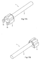
FIGS. 17 are perspective views of magnetic elements according to anotherEmbodiment 12 of the present invention, in which (A) illustrates a magnetic element having a base at one end while (B) illustrates a magnetic element having a base at the other end. - 1 magnetic element, 2 core, 2a end surface, 2b,2d,2e,2f,2g recess, 2h,2i,2j,2k,2m,2n protrusion, 3,4 base
- Now, embodiments of the present invention are described with reference to the drawings. First, a
magnetic element 1 according toEmbodiment 1 is described with reference toFIGS. 1 to 5 . -
FIG. 1 is a perspective view illustrating themagnetic element 1 according to the embodiment of the present invention.FIG. 2 is an exploded perspective view of themagnetic element 1 illustrated inFIG. 1 .FIGS. 3 are diagrams illustrating acore 2 illustrated inFIG. 1 , in which (A) illustrates thecore 2 viewed from a direction perpendicular to an axial direction while (B) illustrates thecore 2 viewed from the axial direction.FIG. 4 is a cross-sectional view of a fixing part of abase 3 with respect to thecore 2 illustrated inFIG. 1 . - The
magnetic element 1 of this embodiment is used for an electronic component or an electronic device such as an antenna device constituting an electronic key system of an automobile or an IC tag. Themagnetic element 1 includes thecore 2 made of a magnetic material,bases core 2, and conductor wire (not shown) wound around an outer periphery of thecore 2, as illustrated inFIG. 1 . - The
core 2 is made of a magnetic material as described above. For instance, thecore 2 is made of a magnetic material such as Mn-Zn ferrite or Ni-Zn ferrite. Thecore 2 is formed to have a linear elongated rod-like shape. Specifically, thecore 2 is formed to have a cylindrical (or substantially cylindrical) shape. In addition, thecore 2 is provided with arecess 2b that is recessed inward from anend surface 2a as illustrated inFIG. 3 . Specifically, thecore 2 is provided with therecess 2b like a round hole having a bottom formed radially inward of thecore 2. In other words, a cross-section parallel to theend surface 2a of therecess 2b (cross-section perpendicular to the axial direction of the core 2) is formed to have a circular shape (or substantially circular shape) having a constant diameter. In other words, therecess 2b is formed to have a circular shape (or substantially circular shape) when viewed from the axial direction. In addition, therecess 2b is formed in theend surface 2a of each end portion of thecore 2. - The
bases base 3 is fixed to one end portion of thecore 2 and thebase 4 is fixed to the other end portion of thecore 2. Specifically, thebases core 2 so that mounting surfaces with respect to a mounting substrate or the like to which themagnetic element 1 is mounted become parallel to each other (surface corresponding to the backside of the paper ofFIG. 1 , or lower side ofFIG. 4 ). In addition, thebases core 2 so that thebases core 2 at the end portions. - The
base 3 arranged at one end is provided with twoterminal portions 3a to which end portions of the conductor wire wound around thecore 2 are fixed by being wound around the same. Theterminal portions 3a are formed so as to protrude outward in the axial direction of thecore 2. Note that thebase 4 is formed similarly to thebase 3 except for provision of theterminal portions 3a. - In this embodiment, as described later, the
bases core 2 by insert molding. For this purpose, thebases arrangement holes core 2 are arranged. In addition, a resin that forms thebases recess 2b as illustrated inFIG. 4 . Note that in this embodiment thebases core 2 by insert molding so that flatness of the mounting surfaces of thebases - The conductor wire (not shown) wound around the outer periphery of the
core 2 is obtained by covering the surface of the conductive wire material with an insulating coating. Each of the end portions of the conductor wire is wound around theterminal portion 3a of thebase 3 so as to be fixed. Specifically, the end portion of the wound conductor wire is soldered so that each of the end portions of the conductor wire is fixed to theterminal portion 3a. - The
magnetic element 1 having the structure described above is manufactured as follows. - First, an original body of the
core 2 is formed from powder of magnetic material such as ferrite by a press using a molding die. In other words, the original body of thecore 2 is formed by powder press molding. After that, the original body of thecore 2 is subjected to cutting so that thecore 2 is formed. Specifically, the end surfaces 2a of both end portions are formed, and therecesses 2b are formed so as to be recessed inward from the end surfaces 2a, by cutting. Thecore 2 is completed by this cutting. - After that, the
bases core 2 by the insert molding in which the both end portions of thecore 2 are arranged in the die for performing resin molding. In other words, the both end portions of thecore 2 are placed in the die, resin is filled in the die, and the resin in the die is stiffened. Thebases FIG. 2 and the like are formed by this insert molding. In addition, during this insert molding method, the resin that forms thebases recesses 2b of thecore 2. - After that, one end of the conductor wire is wound around one
terminal portion 3a and is bound. In this state, the conductor wire is wound around the outer periphery of thecore 2. After the conductor wire is wound a predetermined number of times, the other end portion of the conductor wire is wound around the otherterminal portion 3a and is bound. After that, the end portions of the conductor wire wound around theterminal portions 3a are soldered so that themagnetic element 1 is completed. - As described above, according to the
magnetic element 1 ofEmbodiment 1, thecore 2 is provided with therecesses 2b that are formed to be recessed inward from theend surface 2a. Therefore, when thebases recess 2b. Therefore, in addition to the end surfaces 2a of thecore 2 and the outer peripheral surfaces at the end portions of thecore 2, the inner walls of therecesses 2b contact with the resin that forms thebases bases core 2 can be increased, and hence the contact resistance between each of thebases core 2 can be increased. As a result, in this embodiment, even if thebases core 2 by the insert molding, the fixing strength of thebases core 2 can be enhanced. - The effect of this embodiment is described more concretely based on experimental data.
FIG. 5 illustrates experimental data showing the effect of themagnetic element 1 according to the embodiment of the present invention. - As the experiment, there was measured the fixing strength of the
bases core 2 in the axial direction of the core 2 (i.e. , strength against detachment) when a total length L1 of thecore 2 illustrated inFIG. 3 is 8.8 mm, an outer diameter D1 of thecore 2 is 0.9 mm, a depth L2 from theend surface 2a to the bottom of therecess 2b is 0.5 mm, and an inner diameter D2 of therecess 2b is 0.5 mm. In this measurement, twenty samples were used. The results are shown in the column of "EMBODIMENT" inFIG. 5 . In addition, for comparison, a core which has the same total length L1 and the same outer diameter D1 as thecore 2 and is not provided with therecess 2b (this core is referred to as "core 52" for convenience sake) was measured regarding the strength against detachment of thebases 3 and 4 (fixing strength of the core 52 in the axial direction). In this measurement too, twenty samples were used. The results are shown in the column of "COMPARISON REFERENCE" inFIG. 5 . Note that material of thecores 2 and 52 used in this experiment is manganese ferrite, and material of thebases - As illustrated in
FIG. 5 , an average value of the strength against detachment of thebases core 2 was 13.31 N (Newton), a maximum value of the same was 15.6 N, and a minimum value of the same was 12 N. In contrast, the average value of the strength against detachment of thebases bases core 2 was much higher than the strength against detachment of thebases bases core 2 was 1.9 times the average value of the strength against detachment of thebases - In this way, according to this embodiment, the strength against detachment of the
bases core 2 can be increased substantially. In addition, the contact area between each of thebases core 2 can be increased, and hence the fixing strength of thebases core 2 in the circumferential direction of thecore 2 can also be increased. As a result, according to this embodiment, the fixing strength of thebases core 2 can be increased even if thebases core 2 by the insert molding. - Note that it is obvious from the results of the experiment described above that, if the structure of this embodiment is adopted in the case where the outer diameter of the
core 2 is relatively small like 0.9 mm, an outstanding effect can be obtained. In other words, the structure of this embodiment is more suitable for a smallmagnetic element 1. - According to this embodiment, the
recesses 2b are formed to have a circular shape when viewed from the axial direction. Therefore, for example, compared with the case where therecesses 2b are formed to have a polygonal shape viewed from the axial direction, thecore 2 can be formed accurately, and therecesses 2b can be formed easily. In other words, if therecesses 2b are formed to have a polygonal shape when viewed from the axial direction, it is necessary to form therecesses 2b by the powder press molding, and hence it is difficult to increase accuracy of thecore 2 in the longitudinal direction because thecore 2 is formed only by the powder press molding. In addition, if the diameter of thecore 2 is decreased, it is difficult to form therecess 2b by the die because of a strength problem of the die. In contrast, if therecess 2b is formed to have a circular shape when viewed from the axial direction, accuracy of thecore 2 in the longitudinal direction can be increased by the cutting after the powder press molding, and therecess 2b can be formed easily. - According to this embodiment, the
core 2 is formed to have a cylindrical shape. For this reason, compared with the case where thecore 2 is formed to have a polygonal column shape, warping of thecore 2 after the powder press molding can be suppressed so that thecore 2 can be formed accurately. In addition, according to this embodiment, even if thecore 2 is formed to have a cylindrical shape, the fixing strength of thebases core 2 in the circumferential direction of thecore 2 can be increased as described above. Therefore, even in this case, it is not necessary to provide an additional structure for stopping rotation of thebases core 2 so that the structure of themagnetic element 1 can be simplified. In addition, according to this embodiment, the inner surfaces of therecesses 2b are formed in parallel to the center axis of thecore 2 in the axial direction. This facilitates grinding and coding of thecore 2 after the powder press molding so that constant quality can be secured easily, compared with the case where the inner surfaces of therecesses 2b are formed not in parallel to the center axis of thecore 2 but in a manner of crossing the same so as to form an inclined surface. - According to this embodiment, as illustrated in
FIG. 4 , the length (L2) of the portion recessed inward from theend surface 2a of thecore 2 is shorter than the length (L3) from theend surface 3c of thebase 3 facing thecore 2 to theend surface 2a. This is for the purpose of avoiding a decrease in the fixing strength of thecore 2 when a stress is exerted on thecore 2 in the case where a position of the bottom surface of therecess 2b corresponds to a position of theend surface 3c of thebase 3 on the side to be fixed to the core 2 (in the case where the lengths L2 and L3 correspond to each other) and in the case where L2 is longer than L3. - (Other embodiments) In the embodiment described above, the end surfaces 2a of the both end portions are formed and the
recesses 2b that are recessed inward from the end surfaces 2a are also formed by the cutting after the powder press molding. Alternatively, for example, therecesses 2b that are recessed inward from the end surfaces 2a may be formed in the original body of thecore 2 by the powder press molding. Even in this case, therecesses 2b are formed to have a circular shape when viewed from the axial direction, and hence the die for the powder press molding can be simplified compared with the case where therecesses 2b are formed to have a polygonal shape when viewed from the axial direction. Therefore, even if the diameter of thecore 2 is decreased, strength of the die can be increased so that therecesses 2b can be formed easily by the die. Further, in this case, strength of thecore 2 itself can also be improved. Note that one end portion of the original body of thecore 2 should be polished in this case so that accuracy of thecore 2 in the longitudinal direction can be secured. - According to
Embodiment 1 described above, therecesses 2b are formed so as to have a circular shape when the end surfaces 2a are viewed from the axial direction. Alternatively, for example, recesses 2d having a D-shape as a shape other than a perfect circle when the end surfaces 2a are viewed from the axial direction may be formed in the end surfaces 2a of thecore 2 like anotherEmbodiment 2 illustrated inFIG. 6(A) . Alternatively,recesses 2e having a rectangular shape when viewed from the axial direction may be formed in the end surfaces 2a of thecore 2 like anotherEmbodiment 2 illustrated inFIG. 6(B) . Alternatively, recesses having a polygonal shape (such as a triangular shape and a pentagonal shape) other than the rectangular shape or an elliptic shape when the end surfaces 2a are viewed from the axial direction may be formed in thecore 2. Alternatively,recesses 2f having a linear and grooved shape may be formed in the end surfaces 2a of thecore 2 like anotherEmbodiment 3 illustrated inFIGS. 7 . If the structures illustrated inFIGS. 6 and 7 are adapted, the contact resistance between each of thebases core 2 can be increased. In addition, rotation of thecore 2 illustrated inFIGS. 6 and 7 in the circumferential direction can be prevented, and hence the positional shift of thebases FIGS. 6 and 7 , the fixing strength of thebases core 2 in the circumferential direction can be enhanced even if thebases core 2 by the insert molding. - In addition, like another
Embodiment 4 illustrated inFIGS. 8 and anotherEmbodiment 5 illustrated inFIGS. 9 , the center axis X1 or X2 of therecesses core 2 so as to be shifted from the center axis X3 of thecore 2. In this case, the fixing strength of thecore 2 with respect to thebases core 2 with respect to thebases - Further, in the embodiments described above, the
recesses Embodiment 6 illustrated inFIG. 10 , there may be formedrecesses 2g having an tapered cylinder shape in which the inner surface 2g1 is not parallel to the center axis X3 of thecore 2 but crosses the same so as to have an inclined surface, and the cross-sectional area increases gradually toward the depth direction of thecore 2. Note that therecesses 2g formed in the tapered cylinder shape may be modified to have a tapered polygonal column shape. - In
Embodiment 1 described above, thecore 2 is provided with therecesses 2b that are formed to be recessed from the end surfaces 2a inward in the radial direction of thecore 2. Alternatively, for example, as illustrated inFIG. 11(A) ,protrusions 2h may be formed on the end surfaces 2a of thecore 2 so that only the tips of thecore 2 are protruded. In this case, as illustrated inFIG. 11(A) , it is preferable that the outer surfaces of theprotrusions 2h should be formed to be parallel to the center axis of thecore 2. In addition, like anotherEmbodiment 8 illustrated inFIG. 11(B) , the cross-sectional area of theprotrusion 2i that is parallel to theend surface 2a of thecore 2 may be formed to increase gradually toward the tip of theprotrusion 2i. If the structure illustrated inFIG. 11(B) is adopted, thecore 2 is hardly detached from thebases - In addition, as illustrated in
FIG. 12 , it is preferable that a length (L4) of theprotrusion 2h from the tip 2ha of the protruding portion to theend surface 2a should be shorter than a length (L5) of thebase 3 from theend surface 3c facing thecore 2 to theprotrusion 2h. This is for the purpose of avoiding a decrease in the fixing strength of thecore 2 when a stress is exerted on thecore 2 in the case where a position of the bottom surface of theprotrusion 2h corresponds to a position of theend surface 3c of thebase 3 on the side to be fixed to the core 2 (in the case where the lengths L4 and L5 correspond to each other) and in the case where L4 is longer than L5. - In addition, like another
Embodiment 8 illustrated inFIG. 13(A) , only a part of theend surface 2a is cut out when thecore 2 is viewed from the axial direction so that the remaining protruding part becomes theprotrusion 2j. - In addition, like another
Embodiment 9 illustrated inFIGS. 14 or anotherEmbodiment 10 illustrated inFIGS. 15 , D-shape protrusions 2k orrectangular shape protrusions 2m may be adopted similarly to therecesses protrusions core 2. Note that the center axis X3 of theprotrusions bases core 2 can be increased so that the fixing strength of thebases core 2 can be enhanced. - In addition, like another
Embodiment 11 illustrated inFIG. 16(A) ,protrusions 2n may be formed so as to cross thecore 2 sectionally or longitudinally with respect to the radial direction viewed from the axial direction. When theprotrusion 2n is viewed from the g-direction as illustrated inFIG. 16(B) , theprotrusion 2n is formed from one end of the outer periphery to the other end of the outer periphery. Even in this structure, the contact area between each of thebases core 2 can be increased so that the fixing strength of thebases core 2 can be enhanced. - In each embodiment described above, the
core 2 is formed to have a cylindrical shape. Alternatively, for example, thecore 2 may be formed to have a polygonal column shape such as a rectangular column shape or a pentagonal column shape. Alternatively, thecore 2 may be formed to have an elliptic cylinder shape. Further, in each embodiment described above, the center axis X3 of thecore 2 and the center axis of the recess or the protrusion are the same or parallel to each other, but the center axes may be neither the same nor parallel to each other. - In each embodiment described above, the
bases core 2. Alternatively, for example, like anotherEmbodiment 12 illustrated inFIG. 17(A) or 17(B) , thebase core 2. In this case, therecess 2b may be formed only in theend surface 2a on the side to which thebase recess 2b may be formed in eachend surface 2a of both sides of thecore 2. Further, in the above-mentioned embodiments, the example having onecore 2 and twobases core 2 and onebase 3 or having onecore 2 and onebase 4 is described, but it is possible to adopt the magnetic element including twocores 2 and onebase 3, the magnetic element including twocores 2 and twobases core 2 and three bases. - In each embodiment described above, the
base 3 is provided with the twoterminal portions 3a, but it is possible that each of thebases base 3 and/orbase 4. Further, the magnetic element described above includes the conductor wire, but the magnetic element may be one in the state without the conductor wire. In addition, a contour line of the inner surface constituting the recess such as therecess 2b or a contour line of the outer surface constituting the protrusion such as theprotrusion 2h are formed to be parallel or substantially parallel to the center axis X3 of thecore 2. In this application, however, the term "parallel" is used so as to include the case where they are substantially parallel as illustrated inFIG. 10 and 11(B) (case where the inclination with respect to the center axis X3 is 10 degrees or smaller). Note that these contour lines may not be parallel.
Claims (14)
- A magnetic element, comprising a core made of a magnetic material and a base made of resin that is formed by insert molding so as to be fixed to at least one of end portions of the core, wherein the base is provided with a recess or a protrusion formed on an end surface of the one of end portions of the core.
- A magnetic element according to claim 1, wherein an inner surface of the recess or an outer surface of the protrusion is formed so as to be parallel to a center axis of the core.
- A magnetic element according to claim 1, wherein the recess has a circular shape when the end surface of the core is viewed from the axial direction.
- A magnetic element according to claim 1, wherein the recess has a polygonal shape when the end surface of the core is viewed from the axial direction.
- A magnetic element according to claim 1, wherein the protrusion has a circular shape when the end surface of the core is viewed from the axial direction.
- A magnetic element according to claim 1, wherein the protrusion has a polygonal shape when the end surface of the core is viewed from the axial direction.
- A magnetic element according to any one of claims 1 to6, wherein the center axis of the cross-section of the recess or the protrusion, the cross-section being parallel to the end surface of the core, is formed so as to shift from the center axis of the core.
- A magnetic element according to claim 1, wherein the recess is formed like a groove in a radial direction of the end surface of the core, and the protrusion is formed linearly on the end surface of the core.
- A magnetic element according to claim 2, wherein the recess is formed so that the cross-section being parallel to the end surface of the core may becomes a shape other than a perfect circle.
- A magnetic element according to claim 1, wherein a length of a part of the recess that is recessed inward from the end surface of the core to which the base is fixed is formed to be shorter than a length of the base from an end surface on a side that is fixed to the core to a part of the recess that contacts with the end surface.
- A magnetic element according to claim 1, wherein a length from a tip of the protrusion to the end surface of the core is formed to be shorter than a length from an end surface of the base on a side that is fixed to the core to a part that comes in contact with the tip of the protrusion.
- A magnetic element according to claim 1, wherein a cross-sectional area of the recess being parallel to the end surface of the core is formed to increases gradually toward a depth direction of the recess.
- A magnetic element according to claim 1, wherein a cross-sectional area of the protrusion being parallel to the end surface of the core is formed increases gradually toward a tip direction of the protrusion.
- An antenna device using the magnetic element according to any one of claims 1 to 13.
Applications Claiming Priority (2)
| Application Number | Priority Date | Filing Date | Title |
|---|---|---|---|
| JP2007160875 | 2007-06-19 | ||
| PCT/JP2008/061251 WO2008156145A1 (en) | 2007-06-19 | 2008-06-19 | Magnetic element, and antenna device using the magnetic element |
Publications (2)
| Publication Number | Publication Date |
|---|---|
| EP2172948A1 true EP2172948A1 (en) | 2010-04-07 |
| EP2172948A4 EP2172948A4 (en) | 2010-07-21 |
Family
ID=40156303
Family Applications (1)
| Application Number | Title | Priority Date | Filing Date |
|---|---|---|---|
| EP08777411A Withdrawn EP2172948A4 (en) | 2007-06-19 | 2008-06-19 | MAGNETIC ELEMENT AND ANTENNA DEVICE USING THE MAGNETIC ELEMENT |
Country Status (5)
| Country | Link |
|---|---|
| US (1) | US8487731B2 (en) |
| EP (1) | EP2172948A4 (en) |
| JP (1) | JPWO2008156145A1 (en) |
| CN (1) | CN101681710A (en) |
| WO (1) | WO2008156145A1 (en) |
Families Citing this family (3)
| Publication number | Priority date | Publication date | Assignee | Title |
|---|---|---|---|---|
| CN101661829B (en) * | 2009-08-07 | 2014-10-29 | 越峰电子(昆山)有限公司 | Combined type soft ferrite magnetic core |
| JP5212329B2 (en) * | 2009-10-12 | 2013-06-19 | 株式会社デンソー | Ignition coil manufacturing method |
| CN105825997B (en) * | 2015-01-22 | 2019-03-22 | 株式会社村田制作所 | Coil parts |
Family Cites Families (26)
| Publication number | Priority date | Publication date | Assignee | Title |
|---|---|---|---|---|
| US4419640A (en) * | 1979-12-17 | 1983-12-06 | Omron Tateisi Electronics Co. | Unitary contact-terminal blades integrally formed in a molded base |
| JPS5731810U (en) * | 1980-07-31 | 1982-02-19 | ||
| JPS5854111U (en) * | 1981-10-09 | 1983-04-13 | シチズン時計株式会社 | Bar antenna coil for ultra-compact radio receiver |
| JPS5895009U (en) * | 1981-12-21 | 1983-06-28 | 松下電器産業株式会社 | high frequency coil |
| JPS629609A (en) * | 1985-07-05 | 1987-01-17 | Matsushita Electric Ind Co Ltd | High-frequency transformer |
| JPS6416719U (en) * | 1987-07-20 | 1989-01-27 | ||
| JPH02150004A (en) | 1988-11-30 | 1990-06-08 | Toko Inc | Inductance element |
| JPH0279004U (en) * | 1988-12-05 | 1990-06-18 | ||
| JP2927084B2 (en) * | 1991-11-13 | 1999-07-28 | トヨタ自動車株式会社 | Manufacturing method of electromagnetic pickup |
| JP2987666B2 (en) * | 1992-10-13 | 1999-12-06 | 太陽誘電株式会社 | Linearity coil |
| JPH08167528A (en) | 1994-12-14 | 1996-06-25 | Taiyo Yuden Co Ltd | Linearity coil |
| JPH0992542A (en) * | 1995-07-19 | 1997-04-04 | Taiyo Yuden Co Ltd | Linearity coil |
| GB9621334D0 (en) * | 1996-10-12 | 1996-11-27 | Lucas Ind Inc | Rotary solenoid |
| DE19713659C1 (en) * | 1997-04-02 | 1998-06-25 | Siemens Ag | Vertical structure electromagnetic relay |
| JP3369075B2 (en) * | 1997-04-30 | 2003-01-20 | 東京パーツ工業株式会社 | Surface mount coil |
| JPH118133A (en) | 1997-06-16 | 1999-01-12 | Tokyo Parts Ind Co Ltd | Surface mounting coil |
| DE19812836A1 (en) | 1998-03-24 | 1999-09-30 | Pemetzrieder Neosid | Inductive miniature component for SMD assembly |
| JP2000309031A (en) * | 1999-04-26 | 2000-11-07 | Ibiden Co Ltd | Resin molded article having ceramic sintered body as core, and its manufacture |
| CN1181509C (en) * | 2000-09-14 | 2004-12-22 | 松下电工株式会社 | Electromagnetic device, high voltage generator, and method for manufacturing electromagnetic device |
| JP2004235701A (en) * | 2003-01-28 | 2004-08-19 | Casio Comput Co Ltd | Antenna and wristwatch with antenna |
| KR20050078988A (en) * | 2004-02-03 | 2005-08-08 | 타이코 일렉트로닉스 에이엠피 게엠베하 | Electromagnetic relay having at least one relay auctuator and a receptacle for relay actuators |
| US7785424B2 (en) * | 2004-08-23 | 2010-08-31 | Nippon Kagaku Yakin Co., Ltd. | Method of making a magnetic core part |
| JP4787604B2 (en) * | 2005-11-18 | 2011-10-05 | 富士通コンポーネント株式会社 | Coil device |
| JP2007240401A (en) * | 2006-03-10 | 2007-09-20 | Casio Comput Co Ltd | Radio clock and antenna device |
| JP4432977B2 (en) * | 2007-01-30 | 2010-03-17 | Tdk株式会社 | Coil parts |
| JP5544721B2 (en) * | 2009-02-03 | 2014-07-09 | スミダコーポレーション株式会社 | Magnetic element |
-
2008
- 2008-06-19 CN CN200880018033A patent/CN101681710A/en active Pending
- 2008-06-19 JP JP2009520535A patent/JPWO2008156145A1/en active Pending
- 2008-06-19 WO PCT/JP2008/061251 patent/WO2008156145A1/en not_active Ceased
- 2008-06-19 US US12/665,756 patent/US8487731B2/en active Active
- 2008-06-19 EP EP08777411A patent/EP2172948A4/en not_active Withdrawn
Also Published As
| Publication number | Publication date |
|---|---|
| CN101681710A (en) | 2010-03-24 |
| US8487731B2 (en) | 2013-07-16 |
| US20100188180A1 (en) | 2010-07-29 |
| WO2008156145A1 (en) | 2008-12-24 |
| EP2172948A4 (en) | 2010-07-21 |
| JPWO2008156145A1 (en) | 2010-08-26 |
Similar Documents
| Publication | Publication Date | Title |
|---|---|---|
| JP6822129B2 (en) | Surface mount inductor | |
| KR101060402B1 (en) | Waterproof connector and its manufacturing method | |
| EP2455952B1 (en) | Magnetic element | |
| CN109494051B (en) | Drum-shaped core and coil component | |
| EP2929360B1 (en) | Electrical current transducer with grounding device | |
| JP2004273490A (en) | Wire-wound common mode choke coil and its manufacturing method | |
| JP7610354B2 (en) | antenna | |
| JP2004193215A (en) | Electronic component and method of manufacturing the same | |
| US8487731B2 (en) | Magnetic element, and antenna device using the magnetic element | |
| WO2005045859A1 (en) | Coil device | |
| JP5922567B2 (en) | Pressure sensitive element holding device for electronic pen | |
| EP1710816B1 (en) | Transformer | |
| JP3846798B2 (en) | Coil device manufacturing method | |
| JP2006080107A (en) | Coil device | |
| JP7021839B2 (en) | Magnetic sensor | |
| US7733283B2 (en) | Antenna Device | |
| JP5915588B2 (en) | Coil and coil manufacturing method | |
| JP2017163095A (en) | Coil device | |
| CN105825997A (en) | Coil component | |
| US20190378641A1 (en) | Inductor and inductor manufacturing method | |
| JP5954115B2 (en) | Coil device for electronic pen | |
| JP6052454B2 (en) | Coil device for electronic pen | |
| JP2007311622A (en) | Small surface mount electronic component and its manufacturing method | |
| JP4221000B2 (en) | Rotation sensor | |
| EP4439083A1 (en) | Current sensing device |
Legal Events
| Date | Code | Title | Description |
|---|---|---|---|
| PUAI | Public reference made under article 153(3) epc to a published international application that has entered the european phase |
Free format text: ORIGINAL CODE: 0009012 |
|
| 17P | Request for examination filed |
Effective date: 20100119 |
|
| AK | Designated contracting states |
Kind code of ref document: A1 Designated state(s): AT BE BG CH CY CZ DE DK EE ES FI FR GB GR HR HU IE IS IT LI LT LU LV MC MT NL NO PL PT RO SE SI SK TR |
|
| AX | Request for extension of the european patent |
Extension state: AL BA MK RS |
|
| A4 | Supplementary search report drawn up and despatched |
Effective date: 20100623 |
|
| RIC1 | Information provided on ipc code assigned before grant |
Ipc: H01F 27/26 20060101ALI20100617BHEP Ipc: H01Q 7/08 20060101ALI20100617BHEP Ipc: H01F 27/255 20060101ALI20100617BHEP Ipc: H01F 3/08 20060101AFI20090116BHEP |
|
| DAX | Request for extension of the european patent (deleted) | ||
| 17Q | First examination report despatched |
Effective date: 20110301 |
|
| STAA | Information on the status of an ep patent application or granted ep patent |
Free format text: STATUS: THE APPLICATION IS DEEMED TO BE WITHDRAWN |
|
| 18D | Application deemed to be withdrawn |
Effective date: 20140102 |