EP2172624A1 - Method for detecting amount of particulate matter collected, device for detecting amount of particulate matter, and emission gas purifier - Google Patents
Method for detecting amount of particulate matter collected, device for detecting amount of particulate matter, and emission gas purifier Download PDFInfo
- Publication number
- EP2172624A1 EP2172624A1 EP08777477A EP08777477A EP2172624A1 EP 2172624 A1 EP2172624 A1 EP 2172624A1 EP 08777477 A EP08777477 A EP 08777477A EP 08777477 A EP08777477 A EP 08777477A EP 2172624 A1 EP2172624 A1 EP 2172624A1
- Authority
- EP
- European Patent Office
- Prior art keywords
- pms
- filter
- collection
- exhaust
- amount
- Prior art date
- Legal status (The legal status is an assumption and is not a legal conclusion. Google has not performed a legal analysis and makes no representation as to the accuracy of the status listed.)
- Granted
Links
Images

Classifications
-
- B—PERFORMING OPERATIONS; TRANSPORTING
- B01—PHYSICAL OR CHEMICAL PROCESSES OR APPARATUS IN GENERAL
- B01D—SEPARATION
- B01D46/00—Filters or filtering processes specially modified for separating dispersed particles from gases or vapours
- B01D46/42—Auxiliary equipment or operation thereof
- B01D46/44—Auxiliary equipment or operation thereof controlling filtration
- B01D46/442—Auxiliary equipment or operation thereof controlling filtration by measuring the concentration of particles
-
- F—MECHANICAL ENGINEERING; LIGHTING; HEATING; WEAPONS; BLASTING
- F01—MACHINES OR ENGINES IN GENERAL; ENGINE PLANTS IN GENERAL; STEAM ENGINES
- F01N—GAS-FLOW SILENCERS OR EXHAUST APPARATUS FOR MACHINES OR ENGINES IN GENERAL; GAS-FLOW SILENCERS OR EXHAUST APPARATUS FOR INTERNAL-COMBUSTION ENGINES
- F01N3/00—Exhaust or silencing apparatus having means for purifying, rendering innocuous, or otherwise treating exhaust
- F01N3/02—Exhaust or silencing apparatus having means for purifying, rendering innocuous, or otherwise treating exhaust for cooling, or for removing solid constituents of, exhaust
-
- B—PERFORMING OPERATIONS; TRANSPORTING
- B01—PHYSICAL OR CHEMICAL PROCESSES OR APPARATUS IN GENERAL
- B01D—SEPARATION
- B01D46/00—Filters or filtering processes specially modified for separating dispersed particles from gases or vapours
- B01D46/0084—Filters or filtering processes specially modified for separating dispersed particles from gases or vapours provided with safety means
- B01D46/0086—Filter condition indicators
-
- B—PERFORMING OPERATIONS; TRANSPORTING
- B01—PHYSICAL OR CHEMICAL PROCESSES OR APPARATUS IN GENERAL
- B01D—SEPARATION
- B01D46/00—Filters or filtering processes specially modified for separating dispersed particles from gases or vapours
- B01D46/24—Particle separators, e.g. dust precipitators, using rigid hollow filter bodies
- B01D46/2403—Particle separators, e.g. dust precipitators, using rigid hollow filter bodies characterised by the physical shape or structure of the filtering element
- B01D46/2418—Honeycomb filters
-
- B—PERFORMING OPERATIONS; TRANSPORTING
- B01—PHYSICAL OR CHEMICAL PROCESSES OR APPARATUS IN GENERAL
- B01D—SEPARATION
- B01D46/00—Filters or filtering processes specially modified for separating dispersed particles from gases or vapours
- B01D46/66—Regeneration of the filtering material or filter elements inside the filter
- B01D46/80—Chemical processes for the removal of the retained particles, e.g. by burning
- B01D46/84—Chemical processes for the removal of the retained particles, e.g. by burning by heating only
-
- F—MECHANICAL ENGINEERING; LIGHTING; HEATING; WEAPONS; BLASTING
- F01—MACHINES OR ENGINES IN GENERAL; ENGINE PLANTS IN GENERAL; STEAM ENGINES
- F01N—GAS-FLOW SILENCERS OR EXHAUST APPARATUS FOR MACHINES OR ENGINES IN GENERAL; GAS-FLOW SILENCERS OR EXHAUST APPARATUS FOR INTERNAL-COMBUSTION ENGINES
- F01N3/00—Exhaust or silencing apparatus having means for purifying, rendering innocuous, or otherwise treating exhaust
- F01N3/02—Exhaust or silencing apparatus having means for purifying, rendering innocuous, or otherwise treating exhaust for cooling, or for removing solid constituents of, exhaust
- F01N3/021—Exhaust or silencing apparatus having means for purifying, rendering innocuous, or otherwise treating exhaust for cooling, or for removing solid constituents of, exhaust by means of filters
- F01N3/023—Exhaust or silencing apparatus having means for purifying, rendering innocuous, or otherwise treating exhaust for cooling, or for removing solid constituents of, exhaust by means of filters using means for regenerating the filters, e.g. by burning trapped particles
- F01N3/025—Exhaust or silencing apparatus having means for purifying, rendering innocuous, or otherwise treating exhaust for cooling, or for removing solid constituents of, exhaust by means of filters using means for regenerating the filters, e.g. by burning trapped particles using fuel burner or by adding fuel to exhaust
-
- F—MECHANICAL ENGINEERING; LIGHTING; HEATING; WEAPONS; BLASTING
- F01—MACHINES OR ENGINES IN GENERAL; ENGINE PLANTS IN GENERAL; STEAM ENGINES
- F01N—GAS-FLOW SILENCERS OR EXHAUST APPARATUS FOR MACHINES OR ENGINES IN GENERAL; GAS-FLOW SILENCERS OR EXHAUST APPARATUS FOR INTERNAL-COMBUSTION ENGINES
- F01N3/00—Exhaust or silencing apparatus having means for purifying, rendering innocuous, or otherwise treating exhaust
- F01N3/08—Exhaust or silencing apparatus having means for purifying, rendering innocuous, or otherwise treating exhaust for rendering innocuous
-
- F—MECHANICAL ENGINEERING; LIGHTING; HEATING; WEAPONS; BLASTING
- F01—MACHINES OR ENGINES IN GENERAL; ENGINE PLANTS IN GENERAL; STEAM ENGINES
- F01N—GAS-FLOW SILENCERS OR EXHAUST APPARATUS FOR MACHINES OR ENGINES IN GENERAL; GAS-FLOW SILENCERS OR EXHAUST APPARATUS FOR INTERNAL-COMBUSTION ENGINES
- F01N9/00—Electrical control of exhaust gas treating apparatus
- F01N9/002—Electrical control of exhaust gas treating apparatus of filter regeneration
-
- B—PERFORMING OPERATIONS; TRANSPORTING
- B01—PHYSICAL OR CHEMICAL PROCESSES OR APPARATUS IN GENERAL
- B01D—SEPARATION
- B01D2273/00—Operation of filters specially adapted for separating dispersed particles from gases or vapours
- B01D2273/22—Making use of microwaves, e.g. for measurements
-
- B—PERFORMING OPERATIONS; TRANSPORTING
- B01—PHYSICAL OR CHEMICAL PROCESSES OR APPARATUS IN GENERAL
- B01D—SEPARATION
- B01D2279/00—Filters adapted for separating dispersed particles from gases or vapours specially modified for specific uses
- B01D2279/30—Filters adapted for separating dispersed particles from gases or vapours specially modified for specific uses for treatment of exhaust gases from IC Engines
-
- F—MECHANICAL ENGINEERING; LIGHTING; HEATING; WEAPONS; BLASTING
- F01—MACHINES OR ENGINES IN GENERAL; ENGINE PLANTS IN GENERAL; STEAM ENGINES
- F01N—GAS-FLOW SILENCERS OR EXHAUST APPARATUS FOR MACHINES OR ENGINES IN GENERAL; GAS-FLOW SILENCERS OR EXHAUST APPARATUS FOR INTERNAL-COMBUSTION ENGINES
- F01N2550/00—Monitoring or diagnosing the deterioration of exhaust systems
- F01N2550/04—Filtering activity of particulate filters
-
- F—MECHANICAL ENGINEERING; LIGHTING; HEATING; WEAPONS; BLASTING
- F01—MACHINES OR ENGINES IN GENERAL; ENGINE PLANTS IN GENERAL; STEAM ENGINES
- F01N—GAS-FLOW SILENCERS OR EXHAUST APPARATUS FOR MACHINES OR ENGINES IN GENERAL; GAS-FLOW SILENCERS OR EXHAUST APPARATUS FOR INTERNAL-COMBUSTION ENGINES
- F01N2560/00—Exhaust systems with means for detecting or measuring exhaust gas components or characteristics
- F01N2560/05—Exhaust systems with means for detecting or measuring exhaust gas components or characteristics the means being a particulate sensor
-
- F—MECHANICAL ENGINEERING; LIGHTING; HEATING; WEAPONS; BLASTING
- F01—MACHINES OR ENGINES IN GENERAL; ENGINE PLANTS IN GENERAL; STEAM ENGINES
- F01N—GAS-FLOW SILENCERS OR EXHAUST APPARATUS FOR MACHINES OR ENGINES IN GENERAL; GAS-FLOW SILENCERS OR EXHAUST APPARATUS FOR INTERNAL-COMBUSTION ENGINES
- F01N2560/00—Exhaust systems with means for detecting or measuring exhaust gas components or characteristics
- F01N2560/06—Exhaust systems with means for detecting or measuring exhaust gas components or characteristics the means being a temperature sensor
-
- F—MECHANICAL ENGINEERING; LIGHTING; HEATING; WEAPONS; BLASTING
- F01—MACHINES OR ENGINES IN GENERAL; ENGINE PLANTS IN GENERAL; STEAM ENGINES
- F01N—GAS-FLOW SILENCERS OR EXHAUST APPARATUS FOR MACHINES OR ENGINES IN GENERAL; GAS-FLOW SILENCERS OR EXHAUST APPARATUS FOR INTERNAL-COMBUSTION ENGINES
- F01N2560/00—Exhaust systems with means for detecting or measuring exhaust gas components or characteristics
- F01N2560/08—Exhaust systems with means for detecting or measuring exhaust gas components or characteristics the means being a pressure sensor
-
- F—MECHANICAL ENGINEERING; LIGHTING; HEATING; WEAPONS; BLASTING
- F01—MACHINES OR ENGINES IN GENERAL; ENGINE PLANTS IN GENERAL; STEAM ENGINES
- F01N—GAS-FLOW SILENCERS OR EXHAUST APPARATUS FOR MACHINES OR ENGINES IN GENERAL; GAS-FLOW SILENCERS OR EXHAUST APPARATUS FOR INTERNAL-COMBUSTION ENGINES
- F01N2560/00—Exhaust systems with means for detecting or measuring exhaust gas components or characteristics
- F01N2560/12—Other sensor principles, e.g. using electro conductivity of substrate or radio frequency
-
- Y—GENERAL TAGGING OF NEW TECHNOLOGICAL DEVELOPMENTS; GENERAL TAGGING OF CROSS-SECTIONAL TECHNOLOGIES SPANNING OVER SEVERAL SECTIONS OF THE IPC; TECHNICAL SUBJECTS COVERED BY FORMER USPC CROSS-REFERENCE ART COLLECTIONS [XRACs] AND DIGESTS
- Y02—TECHNOLOGIES OR APPLICATIONS FOR MITIGATION OR ADAPTATION AGAINST CLIMATE CHANGE
- Y02T—CLIMATE CHANGE MITIGATION TECHNOLOGIES RELATED TO TRANSPORTATION
- Y02T10/00—Road transport of goods or passengers
- Y02T10/10—Internal combustion engine [ICE] based vehicles
- Y02T10/40—Engine management systems
Definitions
- the present invention relates to a collection-amount detection method for particulate matters and a collection-amount detection apparatus therefor.
- the present invention can be used in a case of detecting a deposition amount of PMs on a filter that is put in place in the exhaust system of diesel engine, and the like.
- DPFs are those which are completed by plugging both of the opposite ends of the cellular openings of ceramic honeycomb structures alternatively in a checkered manner, for instance; and they comprise inlet-side cells that are plugged on the exhaust-gas downstream side, outlet-side cells that neighbor the inlet-side cells and are plugged on the exhaust-gas upstream side, and cellular partition walls that demarcate the inlet-side cells and outlet-side cells; and they are one for suppressing the discharge of PMs by filtering exhaust gases and then collecting PMs therein with the cellular partition walls' pores.
- a method is set forth, method in which an electric current or voltage that occurs in a secondary coil being wound around the outer periphery of a collector container is detected at the time of flowing an alternating electric current in a primary coil that is wound around the outer periphery of the collector container, and method in which a collection amount of PMs is then calculated from the resulting value. Since induced electromotive forces that correspond to collection amounts of PMs occur, it is possible to calculate the collection amount of PMs by detecting the electric current or voltage that occurs in the secondary coil.
- DPFs are formed of ceramics, such as cordierite, in general, and are used in such a state that they are accommodated within a casing that is made of metal.
- KKAI Japanese Unexamined Patent Publication
- an exhaust-gas converting apparatus in which an amount of PMs is detected by measuring an intensity of electromagnetic wave with a microwave sensor.
- an adhesion amount of PMs is detected as follows: a detection position of microwave is fixed by utilizing the facts that a dielectric constant and induction loss of a filter change when PMs deposit onto the filter, then the phase of microwave changes inside the filter, and eventually an intensity of the microwave changes; then an intensity of the microwave at that location is measured; and then the adhesion amount of PMs is detected by means of a change in the resulting intensity of the microwave.
- the present invention is one which has been done in view of the aforementioned circumstances, and it is an assignment to be solved to detect a collection amount of particulate matters, such PMs, which absorb electromagnetic waves, with ease and with high accuracy.
- a characteristic of a collection-amount detection method for particulate matters according to the present invention which solves the aforementioned assignment lies in that: it is a collection-amount estimation method for estimating a collection amount of particulate matters, which have been collected in a collector container, by putting the collector container in place in a flow passage in which gases including the particulate matters distribute, and it includes:
- a characteristic of a collection-amount detection apparatus for particulate matters according to the present invention lies in that: it includes:
- an exhaust-gas converting apparatus includes:
- the computing means can calculate an absorption coefficient of the electromagnetic waves at the filter, onto which PMs have been collected, from a value being detected by means of the electromagnetic-wave receiving means, and then computes a collection amount of PMs from a ratio with respect to an absorption coefficient of the electromagnetic waves, absorption coefficient which has been measured in advance, at the filter alone onto which no PMs are collected.
- the collection-amount detection method for particulate matters and collection-amount detection apparatus therefor it is possible to detect a collection amount with high accuracy even by one-point measurement, because they use electromagnetic waves whose frequency is dozens of GHz-a few of THz (the wavelength being on mm level), and because they detect the collection amount utilizing the absorption of the electromagnetic waves by means of particulate matters.
- a collection-amount detection apparatus includes a collector container being put in place in a flow passage in which gases including particulate matters distribute, an electromagnetic-wave emitting means for emitting electromagnetic waves whose frequency is dozens of GHz-a few of THz onto the collector container from the outside of the collector container, an electromagnetic-wave receiving means for detecting an intensity of the electromagnetic waves that have transmitted through the collector container, and a computing means for computing a collection amount of the particulate matters from the intensity that has been detected with the electromagnetic-wave receiving means.
- the "particulate matters” being referred to in the present invention are not limited especially as far as they are a substance that absorbs millimeter-wave-level microwaves whose frequency is dozens of GHz-a few of THz, and that eventually converts their energy into thermal energy; and it is possible to exemplify PMs in which carbon makes the majority, magnetic powders such as ferrite flours, and the like.
- millimeter-wave-level microwaves whose frequency is dozens of GHz-a few of THz are used.
- the frequency is lower than this range, they become likely to transmit through the particulate matters that have been collected, and accordingly the detection accuracy of the collection amount lowers.
- the frequency becomes higher than this range, they become less likely to transmit through the particulate matters that have been collected, and consequently the detection accuracy amount lowers likewise. It is especially preferable to use a frequency in the vicinity of 600 GHz.
- the collector container is one which is put in place in a flow passage in which gases including particulate matters distribute.
- this collector container the following are used: those which can transmit millimeter-wave-level microwaves whose frequency is dozens of GHz-a few of THz. It does not matter even if a part of the microwaves are absorbed.
- filters that are made of ceramics such as cordierite, silicon nitride and alumina are used representatively.
- the electromagnetic-wave emitting means is a means for emitting electromagnetic waves whose frequency is dozens of GHz-a few of THz onto the collector container from the outside of the collector container; and it is possible to use magnetrons, and the like, therefor.
- the electromagnetic waves are emitted by way of an incident window, which is formed in the collector container and which is capable of transmitting the electromagnetic waves with dozens of GHz-a few of THz, in the case of a collector container such as an exhaust-gas converting filter that is accommodated in an accommodator container being made of metal.
- this incident window's quality of material it is possible to use ceramics, such as cordierite, silicon nitride and alumina, glass, and so forth.
- the electromagnetic-wave receiving means is one which detects an intensity of the electromagnetic waves that have transmitted through the collector container, and it is possible to use those having been known publicly, such as microwave sensors. It is desirable that the electromagnetic-wave receiving means can be put in place on the opposite side to the electromagnetic-wave emitting means with respect to the collector container, and that it can be put in place in proximity to the collector container.
- an exhaust-gas converting apparatus it is constituted so as to receive the electromagnetic waves with dozens of GHz-a few of THz by way of a radiation window, which is formed in the collector container and which is capable of transmitting the electromagnetic waves, because there is a fear that the electromagnetic-receiving means might be degraded by means of heat.
- This radiation window can be formed of a quality of material, which is the same as those for the incident window, and which exhibits heat resistance.
- the electromagnetic-wave emitting means, and the electromagnetic-wave receiving means are disposed so that they are positioned on the opposite sides to each other with respect to the collector container.
- a cylindrically-configured collector container such as a honeycomb filter
- the computing means computes a collection amount of the particulate matters from an electromagnetic-wave intensity that has been detected with the electromagnetic-wave receiving means. Specifically, it computes the collection amount of the particulate matters by substituting the electromagnetic-wave intensity, which has been detected with the electromagnetic-wave receiving means, into a relational expression between intensity and collection amount that have been determined in advance.
- a receiving intensity of the collector container alone is measured in the first place as a blank, receiving intensity which is for the collector container that is in such a state that no particulate matters are collected thereon. In this way, it is possible to calculate the collection amount of the particulate matters from a difference between that and another receiving intensity in such a state that the particulate matters are collected thereon.
- the computing means can compute an absorption coefficient of the electromagnetic waves at the filter, onto which PMs have been collected, from a value being detected by means of the electromagnetic-wave receiving means, and can then compute a collection amount of PMs from a ratio with respect to an absorption coefficient of the electromagnetic waves, absorption coefficient which has been measured in advance, at the filter alone onto which no PMs are collected. Since the relationship between the collection amount of PMs and the absorption coefficient makes a linear expression, regardless of various factors such as temperatures, by taking the absorption coefficients of the electromagnetic waves as indexes, it is possible to carry out the calculation of the collection amount of PMs with ease and with high accuracy. Note that the absorption coefficient is expressed by the logarithm of transmissivity, and the transmissivity is a proportion of radiation output with respect to incident output.
- the exhaust-gas converting apparatus with a reducing-gas supplying means for supplying a reducing agent into exhaust gases on an upstream side of said filter. It is even allowable that it can be a means for supplying a reducing agent directly into exhaust gases; or it is also allowable that it can be a means for supplying a reducing agent indirectly into exhaust gases by post-injecting the reducing agent inside a cylinder.
- a reducing-gas supplying means for supplying a reducing agent into exhaust gases on an upstream side of said filter. It is even allowable that it can be a means for supplying a reducing agent directly into exhaust gases; or it is also allowable that it can be a means for supplying a reducing agent indirectly into exhaust gases by post-injecting the reducing agent inside a cylinder.
- the temperature of the filter becomes higher than an ignition temperature of the reducing agent, it is possible to burn PMs to recycle the filter, because the reducing agent burns within the filter and then the filter becomes high temperatures of 600 °C or
- an oxidizing catalyst in place on an upstream side of the filter, or to form a catalytic layer onto the filter.
- a reducing-agent supplying means it is desirable to dispose an estimating means for estimating the collection amount of PMs that have been collected onto said filter; and a controlling means for controlling driving of the reducing-agent supplying means based on the collection amount of PMs, collection amount which has been estimated by means of the estimating means. Since it is possible to drive the reducing-agent supplying means at optimum timings by means of this, fuel consumption improves. It is possible for the estimatingmeans to estimate the collection amount of PMs that have been collected onto the filter from the following: differential pressures between those on the filter's upstream side and those on the downstream side; driving times of engine; records of traveling conditions, and the like.
- the estimating means can estimate an amount of PMs that remain within the filter based on at least one of a value being detected by a differential-pressure detecting means for detecting a differential pressure between an upstream side of the filter and a downstream side thereof, and a value being detected by a temperature sensor for detecting a temperature of the filter.
- a differential-pressure detecting means for detecting a differential pressure between an upstream side of the filter and a downstream side thereof
- a temperature sensor for detecting a temperature of the filter.
- water is also an electromagnetic-wave absorber and accordingly an water content within the filter exerts influences to the detected values; it is therefore desirable to estimate an amount of PMs having been collected onto the filter while taking the water content, which is detected using a moisture sensor, or the like, also into account.
- FIG. 1 An exhaust-gas converting apparatus according to the present example is illustrated in Fig. 1 .
- a converter 20 To an exhaust manifold 10 of a diesel engine 1, a converter 20 is connected, converter 20 that is made of steel and in which a cylindrically-configured filter 2 is accommodated. A major part of exhaust gases from the exhaust manifold 10 flow within the converter 20, and are discharged after passing through the filter 2; and a part of the exhaust gases are returned to an intake manifold 13 of the diesel engine 1 by way of a turbocharger 11 and intercooler 12. Moreover, an injection nozzle 14 is put in place in the exhaust manifold 10, and it is thereby constructed so that light oil is injected into the exhaust gases intermittently.
- Thefilter2 makesahoneycomb-configuredwall-flowstructure that has inlet-side cells being plugged on the exhaust-gas downstream side, outlet-side cells neighboring the inlet-side cells and being plugged on the exhaust-gas upstream side, and porous cellular partition walls demarcating the inlet-side cells and outlet-side cells and having a large number of pores; and is formed of cordierite.
- a microwave transmitter 30, and a microwave receiver 31 are set in place on the opposite outer sides at their substantially central section.
- the microwave transmitter 30, and the microwave receiver 31 are put in place respectively on both of the opposite sides that hold the filter 2 between them on a plane that involves the central axis of the filter 2.
- Driving of the microwave transmitter 30 is controlled by means of an ECU 4, and signals that have been received by means of the microwave receiver 31 are being input to the ECU 4.
- an incident window 21 and a radiation window 22 are formed, incident window 21 and radiation window 22 that comprise alumina, and through which microwaves can transmit.
- differential-pressure sensor 23 which is for detecting a difference between an exhaust-gas pressure on an upstream side of the filter 2 and another exhaust-gas pressure on a downstream side thereof, and output signals of the differential-pressure sensor 23 are being input to the ECU 4.
- a temperature sensor 24 is set in place, temperature sensor 24 which is for detecting an exhaust-gas temperature on a downstream side of the filter 2.
- a brand-new filter 2 was used first of all; then a millimeter wave having 600 GHz was transmitted with an input intensity I i from the microwave transmitter 30 without driving the engine 1; and then an output intensity I o , which had been received by the microwave receiver 31, was measured.
- the energy of the millimeter wave that hadbeen transmitted is absorbed by means of the incident window 21, filter 2 and radiation window 22 to a certain extent to become "I i > I o ,” and the transmissivity is expressed by "I o /I i .”
- FIG. 3 A relationship between the collection amount at each of the filters 2 and the transmissivity (I o /I i ) is illustrated in Fig. 3 .
- the relationship between the collection amount of PMs and the transmissivity does not make any linear expression. Therefore, complicated calculations are needed in order to estimate the collection amount of PMs from the transmissivity.
- the microwave transmitter 30 is driven always in such a state that the engine 1 is driven, and then the ECU 4 observes the "PMs Ratio" always. And, the collection amount of PMs is calculated from the relational expression shown in Fig. 4 ; then, in a case where it surpasses a predetermined value that has been set up as such a state that the collection amount of PMs is not becoming too much, the ECU4 drives the injection nozzle 14 to supply light oil into the exhaust gases in a predetermined amount. At this time, although it is preferable that the microwave transmitter 30 can be turned off not to be driven, it is allowable that its driving can be continued.
- the light oil which has been supplied into the exhaust gases, flows into the filter 2, and is ignited and then burned by mean of the filter 2's heat.
- the filter 2 undergoes temperature increment to about 600 °C or more by means of the resulting combustion heat.
- the ECU4 always observes the output signal of the differential-pressure sensor 23 and the output signal of the temperature sensor 24.
- the addition of the light oil is continued until the difference between the pressure on the filter 2' s upstream side and the pressure on the downstream side becomes a predetermined value or less.
- the ECU 4 stops the driving of the injection nozzle 4, thereby preventing the melt loss of the filter 2.
- the relationship between the "PMs Ratio" and the collection amount of PMs makes a linear expression by taking the "PMs Ratio” as an index, it is possible to detect the collection amount of PMs with ease and with high accuracy by measuring the "PMs Ratio.” Moreover, it is possible to detect the distribution of the collected amount of PMs with good accuracy by using millimeter-wave-level microwaves. Therefore, since it is possible to carry out the recycling process for filters securely in such a state that the collection amount of PMs is not becoming too much, it is possible to prevent melt loss, which results from thermorunaway, preemptively. In addition, since it is possible to keep the driving of the injection nozzle 14 minimum, fuel consumption improves.
Landscapes
- Engineering & Computer Science (AREA)
- Chemical & Material Sciences (AREA)
- Chemical Kinetics & Catalysis (AREA)
- Combustion & Propulsion (AREA)
- Mechanical Engineering (AREA)
- General Engineering & Computer Science (AREA)
- Physics & Mathematics (AREA)
- Geometry (AREA)
- Processes For Solid Components From Exhaust (AREA)
- Exhaust Gas After Treatment (AREA)
- Filtering Of Dispersed Particles In Gases (AREA)
Abstract
Description
- The present invention relates to a collection-amount detection method for particulate matters and a collection-amount detection apparatus therefor. The present invention can be used in a case of detecting a deposition amount of PMs on a filter that is put in place in the exhaust system of diesel engine, and the like.
- Regarding gasoline engines,harmful components in the exhaust gases have been reduced securely by means of the strict regulations on the exhaust gases and the technological developments capable of coping with those. However, regarding diesel engines, the exhaust-gas conversion is difficult compared with the gasoline engines because of such unique circumstances that the harmful components are discharged as PMs (soot comprising carbon fine particlesmainly,high-molecular-weight hydrocarbonfine particles, sulfur-system fine particles such as sulfates, and the like).
- As exhaust-gas converting apparatuses for diesel engine that have been developed so far, the following have been known, and can be divided roughly as follows: trapping-type (or wall-flow) exhaust-gas converting apparatuses; and open-type (or straight-flow) exhaust-gas converting apparatuses. Among these, plugged-type honeycomb bodies that are made of ceramic (i.e., diesel PMs filters (hereinafter referred to as "DPFs")) have been known as for one of the trapping-type exhaust-gas converting apparatuses. These DPFs are those which are completed by plugging both of the opposite ends of the cellular openings of ceramic honeycomb structures alternatively in a checkered manner, for instance; and they comprise inlet-side cells that are plugged on the exhaust-gas downstream side, outlet-side cells that neighbor the inlet-side cells and are plugged on the exhaust-gas upstream side, and cellular partition walls that demarcate the inlet-side cells and outlet-side cells; and they are one for suppressing the discharge of PMs by filtering exhaust gases and then collecting PMs therein with the cellular partition walls' pores.
- In DPFs, however, since the exhaust pressure loss increases by means of the deposition of PMs, it is necessary to recover them by means of removing deposited PMs regularly by certain means. Hence, burning deposited PMs and then recovering DPFs forcibly have been carried out heretofore by means of such a method, and the like, in which a reducing agent, such as fuel, is added into exhaust gases; the exhaust gases are subjected to temperature rise by burning them with an oxidizing catalyst that is put in place on the upstream side of a DPF; and the resulting high-temperature exhaust gases are then supplied to the DPF.
- However, at the time of running idly and during low-load/low-speed running, and the like, where low-exhaust-temperature state continues, no oxidation reaction occurs because the oxidizing catalyst or the like is not activated, and accordingly subjecting the exhaust-gas temperatures to temperature rise becomes difficult. Therefore, it becomes difficult to recover DPFs, and consequently the clogging of the DPFs has progressed.
- Accordingly, it is possible to think of raising the exhaust-gas temperatures forcibly when the collection amount of PMs is judged to surpass a predetermined value. For example, data on the discharge amounts of PMs with respect to running conditions are stored in an ECU as a mapping data in advance, then a discharge amount of PMs is estimated from an accumulated value of running times, and then the resulting value is calculated cumulatively to estimate a collection amount of PMs. And, there is a method is available, method in which DPFs are recovered by increasing the exhaust-gas temperatures forcibly at a point of time when the resulting collection amount of PMs is judged to surpass a predetermined amount.
- However, in the case of turning the data on the discharge amount of PMs with respect to running conditions into the mapping data, there is such a problem that the error is great. Moreover, as an index for the collection amount of PMs, it has been carried out as well to use the differential pressure between the pressure in front of a DPF and that in the rear thereof. In this method, however, since the value of limit differential pressure, which makes a standard for the judgment, changes greatly depending on the running conditions of engine, it is needed to store data on the limit differential pressures, which result from the respective running conditions, as another mapping data so that the data volume has become enormous. In addition, there is such a problem that the detection sensitivity is low in a range where the collection amount of PMs is less, because the relationship between the collection amount of PMs and the differential pressure is not in a linear relationship.
- Hence, in Japanese Unexamined Patent Publication (KOKAI) Gazette No.
2005-325,771 - By the way, DPFs are formed of ceramics, such as cordierite, in general, and are used in such a state that they are accommodated within a casing that is made of metal. In a case where the technique that is set forth in Japanese Unexamined Patent Publication (KOKAI) Gazette No.
2005-325,771 - However, exhaust gases distribute within the casing, and accordingly it becomes such a high temperature as 1,000 °C at the time of recovering the DPF forcibly. Moreover, since being also an oxidizing atmosphere is multiplied adversely at the time of recovering it forcibly, the coils have deteriorated early. Therefore, it is not practical to apply the technique being set forth in the aforementioned gazette to the instance when estimating the collection amount of PMs on DPFs.
- Moreover, in Japanese Unexamined Patent Publication (KOKAI) Gazette No.
10-220,219 - However, since the filter's dielectric constant and induction loss come under the influence of temperatures, it is needed to do temperature correction; moreover, since an electromagnetic-field intensity is detected with the microwave sensor while utilizing a standing wave, not a direct phase-difference measurement, it is difficult to separate the effect of the microwave's attenuation by the one-point measurement, and accordingly there is such a problem that it cannot be detected with good accuracy. Consequently, it is needed to evaluate it in a comprehensive manner by carrying out the measurement at a plurality of locations; alternatively, it is needed to do troublesome evaluations using mapping data.
- And, in the 2.45-GHz microwave that has been employed usually as a microwave, since the wavelength is 12 cm approximately so that the resolving power is low, it is not possible to detect the distribution of the collection amount of PMs, distribution whose size is this wavelength or less. Accordingly, it is not possible to prevent melt loss of the filter, melt loss which is caused as follows: PMs have deposited locally and thereby high temperatures have arisen locally, because of thermorunaway, at the time of the control for recycling the filter.
- Patent Literature No. 1: Japanese Unexamined Patent Publication (KOKAI) Gazette No.
2005-325,771 - Patent Literature No. 2: Japanese Unexamined Patent Publication (KOKAI) Gazette No.
10-220,219 - The present invention is one which has been done in view of the aforementioned circumstances, and it is an assignment to be solved to detect a collection amount of particulate matters, such PMs, which absorb electromagnetic waves, with ease and with high accuracy.
- A characteristic of a collection-amount detection method for particulate matters according to the present invention which solves the aforementioned assignment lies in that: it is a collection-amount estimation method for estimating a collection amount of particulate matters, which have been collected in a collector container, by putting the collector container in place in a flow passage in which gases including the particulate matters distribute, and it includes:
- an emission step of emitting electromagnetic waves whose frequency is dozens of GHz-a few of THz onto the collector container from the outside of the collector container; and
- a detection step of detecting an intensity of the electromagnetic waves that have transmitted through the collector container, and then substituting the intensity into a relational expression between intensity and collection amount that have been determined in advance, thereby computing a collection amount of the particulate matters.
- Moreover,a characteristic of a collection-amount detection apparatus for particulate matters according to the present invention lies in that: it includes:
- a collector container being put in place in a flow passage in which gases including particulate matters distribute;
- an electromagnetic-wave emitting means for emitting electromagnetic waves whose frequency is dozens of GHz-a few of THz onto the collector container from the outside of the collector container;
- an electromagnetic-wave receiving means for detecting an intensity of the electromagnetic waves that have transmitted through the collector container; and
- a computing means for computing a collection amount of the particulate matters from the intensity that has been detected with the electromagnetic-wave receiving means.
- In addition, a characteristic of an exhaust-gas converting apparatus according to the present invention lies in that: it includes:
- a filter being put in place in an exhaust-gas flow passage, and being for collecting PMs in which carbon makes the majority;
- an accommodator container for accommodating the filter therein;
- an electromagnetic-wave emitting means for emitting electromagnetic waves whose frequency is dozens of GHz-a few of THz onto the filter through an incident window that is formed in the accommodator container;
- an electromagnetic-wave receiving means for detecting an intensity of the electromagnetic waves that have transmitted through the filter and have then radiated through a radiation window that is formed in the accommodator container; and
- a computing means for computing a collection amount of PMs from the intensity that has been detected with the electromagnetic-wave receiving means.
- In the exhaust-gas converting apparatus according to the present invention, it is desirable that the computing means can calculate an absorption coefficient of the electromagnetic waves at the filter, onto which PMs have been collected, from a value being detected by means of the electromagnetic-wave receiving means, and then computes a collection amount of PMs from a ratio with respect to an absorption coefficient of the electromagnetic waves, absorption coefficient which has been measured in advance, at the filter alone onto which no PMs are collected. Moreover, it is preferable that it can be further equipped with a reducing-agent supplying means for supplying a reducing agent into exhaust gases on an upstream side of the filter; and it is desirable that it can be further equipped with an estimating means for estimating the collection amount of PMs that have been collected onto the filter; and a controlling means for controlling driving of the reducing-agent supplying means based on the collection amount of PMs, collection amount which has been estimated by means of the estimating means.
- In accordance with the collection-amount detection method for particulate matters and collection-amount detection apparatus therefor according to the present invention, it is possible to detect a collection amount with high accuracy even by one-point measurement, because they use electromagnetic waves whose frequency is dozens of GHz-a few of THz (the wavelength being on mm level), and because they detect the collection amount utilizing the absorption of the electromagnetic waves by means of particulate matters.
- And, in accordance with the exhaust-gas converting apparatus according to the present invention, it is possible to prevent melt loss of the filter, melt loss which results from thermorunaway, by carrying out a recycling process in a state where a collection amount of PMs does not become too much, because it is possible to detect the distribution of in the collection amount with good accuracy. Moreover, fuel consumption also improves, because it is possible to make a reducing-agent supply amount into exhaust gases minimum at the time of the recycling process.
-
-
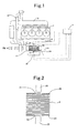
Fig. 1 is a block diagram of an exhaust-gas converting apparatus that is directed to an example according to the present invention; -
Fig. 2 is a major-part-enlarged cross-sectional diagram of an exhaust-gas converting apparatus that is directed to an example according to the present invention; -
Fig. 3 is a graph for illustrating a relationship between collection amounts of PMs and transmissivities; and -
Fig. 4 is a graph for illustrating a relationship between collection amounts of PMs and "PMs Ratios." -
- 1: Engine; 2: Filter; 4: ECU;
- 14: Injection Nozzle; 20: Converter; 21: Incident Window;
- 22: Radiation Window; 23: Differential-pressure Sensor; 24: Temperature Sensor;
- 30: Microwave Transmitter; and 31: Microwave Receiver
- A collection-amount detection apparatus according to the present invention includes a collector container being put in place in a flow passage in which gases including particulate matters distribute, an electromagnetic-wave emitting means for emitting electromagnetic waves whose frequency is dozens of GHz-a few of THz onto the collector container from the outside of the collector container, an electromagnetic-wave receiving means for detecting an intensity of the electromagnetic waves that have transmitted through the collector container, and a computing means for computing a collection amount of the particulate matters from the intensity that has been detected with the electromagnetic-wave receiving means.
- The "particulate matters" being referred to in the present invention are not limited especially as far as they are a substance that absorbs millimeter-wave-level microwaves whose frequency is dozens of GHz-a few of THz, and that eventually converts their energy into thermal energy; and it is possible to exemplify PMs in which carbon makes the majority, magnetic powders such as ferrite flours, and the like.
- Moreover, in the present invention, millimeter-wave-level microwaves whose frequency is dozens of GHz-a few of THz are used. When the frequency is lower than this range, they become likely to transmit through the particulate matters that have been collected, and accordingly the detection accuracy of the collection amount lowers. Moreover, when the frequency becomes higher than this range, they become less likely to transmit through the particulate matters that have been collected, and consequently the detection accuracy amount lowers likewise. It is especially preferable to use a frequency in the vicinity of 600 GHz.
- The collector container is one which is put in place in a flow passage in which gases including particulate matters distribute. As for this collector container, the following are used: those which can transmit millimeter-wave-level microwaves whose frequency is dozens of GHz-a few of THz. It does not matter even if a part of the microwaves are absorbed. In the case of an exhaust-gas converting apparatus, filters that are made of ceramics such as cordierite, silicon nitride and alumina are used representatively.
- The electromagnetic-wave emitting means is a means for emitting electromagnetic waves whose frequency is dozens of GHz-a few of THz onto the collector container from the outside of the collector container; and it is possible to use magnetrons, and the like, therefor. Although it is desirable to emit the electromagnetic waves directly onto the collector container, the electromagnetic waves are emitted by way of an incident window, which is formed in the collector container and which is capable of transmitting the electromagnetic waves with dozens of GHz-a few of THz, in the case of a collector container such as an exhaust-gas converting filter that is accommodated in an accommodator container being made of metal. As for this incident window's quality of material, it is possible to use ceramics, such as cordierite, silicon nitride and alumina, glass, and so forth.
- The electromagnetic-wave receiving means is one which detects an intensity of the electromagnetic waves that have transmitted through the collector container, and it is possible to use those having been known publicly, such as microwave sensors. It is desirable that the electromagnetic-wave receiving means can be put in place on the opposite side to the electromagnetic-wave emitting means with respect to the collector container, and that it can be put in place in proximity to the collector container. However, in the case of an exhaust-gas converting apparatus, it is constituted so as to receive the electromagnetic waves with dozens of GHz-a few of THz by way of a radiation window, which is formed in the collector container and which is capable of transmitting the electromagnetic waves, because there is a fear that the electromagnetic-receiving means might be degraded by means of heat. This radiation window can be formed of a quality of material, which is the same as those for the incident window, and which exhibits heat resistance.
- The electromagnetic-wave emitting means, and the electromagnetic-wave receiving means are disposed so that they are positioned on the opposite sides to each other with respect to the collector container. For example, in the case of a cylindrically-configured collector container such as a honeycomb filter, it is possible to put them in place on both of its opposite sides, respectively, in the diametric direction. Alternatively, on an exhaust-gas inlet side and on an exhaust-gas outlet side, it is also preferable to put them in place so that each of them can be positioned on the opposite sides to each other on a plane that involves each of the axes. By doing thusly, it is possible to detect the collection amount of PMs over the entire length in the exhaust-gas flow direction.
- The computing means computes a collection amount of the particulate matters from an electromagnetic-wave intensity that has been detected with the electromagnetic-wave receiving means. Specifically, it computes the collection amount of the particulate matters by substituting the electromagnetic-wave intensity, which has been detected with the electromagnetic-wave receiving means, into a relational expression between intensity and collection amount that have been determined in advance.
- Since it is often the case that the collector container itself absorbs the electromagnetic waves whose frequency is dozens of GHz-a few of THz to a certain extent, a receiving intensity of the collector container alone is measured in the first place as a blank, receiving intensity which is for the collector container that is in such a state that no particulate matters are collected thereon. In this way, it is possible to calculate the collection amount of the particulate matters from a difference between that and another receiving intensity in such a state that the particulate matters are collected thereon.
- In the case of an exhaust-gas converting apparatus, it is desirable that the computing means can compute an absorption coefficient of the electromagnetic waves at the filter, onto which PMs have been collected, from a value being detected by means of the electromagnetic-wave receiving means, and can then compute a collection amount of PMs from a ratio with respect to an absorption coefficient of the electromagnetic waves, absorption coefficient which has been measured in advance, at the filter alone onto which no PMs are collected. Since the relationship between the collection amount of PMs and the absorption coefficient makes a linear expression, regardless of various factors such as temperatures, by taking the absorption coefficients of the electromagnetic waves as indexes, it is possible to carry out the calculation of the collection amount of PMs with ease and with high accuracy. Note that the absorption coefficient is expressed by the logarithm of transmissivity, and the transmissivity is a proportion of radiation output with respect to incident output.
- In an exhaust-gas converting apparatus, when the collection amount of PMs that have been collected onto the filter gets greater, the pressure loss rises to adversely affect engine performance. Therefore, the following countermeasures are needed: replacing the filter; alternatively carrying out a recycling process in which the filter is heated to burn the collected PMs, and the like. Since replacing the filter is not practical, the recycling process has been carried out in general.
- Hence, it is desirable to further provide the exhaust-gas converting apparatus according to the present invention with a reducing-gas supplying means for supplying a reducing agent into exhaust gases on an upstream side of said filter. It is even allowable that it can be a means for supplying a reducing agent directly into exhaust gases; or it is also allowable that it can be a means for supplying a reducing agent indirectly into exhaust gases by post-injecting the reducing agent inside a cylinder. When the temperature of the filter becomes higher than an ignition temperature of the reducing agent, it is possible to burn PMs to recycle the filter, because the reducing agent burns within the filter and then the filter becomes high temperatures of 600 °C or more, for instance, by means of the resulting combustion heat. As for this reducing-agent supplying means, pumps, injectors, and the like, are available.
- Moreover, it is also preferable to put an oxidizing catalyst in place on an upstream side of the filter, or to form a catalytic layer onto the filter. By doing thusly, even when the temperature of the filter is low temperatures, it is possible to oxidize and then burn the reducing agent by means of catalyst, and accordingly it becomes feasible to recycle the filter by means of the resulting combustion heat.
- In the case of using a reducing-agent supplying means, it is desirable to dispose an estimating means for estimating the collection amount of PMs that have been collected onto said filter; and a controlling means for controlling driving of the reducing-agent supplying means based on the collection amount of PMs, collection amount which has been estimated by means of the estimating means. Since it is possible to drive the reducing-agent supplying means at optimum timings by means of this, fuel consumption improves. It is possible for the estimatingmeans to estimate the collection amount of PMs that have been collected onto the filter from the following: differential pressures between those on the filter's upstream side and those on the downstream side; driving times of engine; records of traveling conditions, and the like.
- At the time of recycle processing, it is also preferable that the estimating means can estimate an amount of PMs that remain within the filter based on at least one of a value being detected by a differential-pressure detecting means for detecting a differential pressure between an upstream side of the filter and a downstream side thereof, and a value being detected by a temperature sensor for detecting a temperature of the filter. When estimating the amount of remaining PMs based on a value that is detected by the differential-pressure estimating means, carrying out the recycle processing wastefully is prevented, and consequently fuel consumption improves furthermore. Moreover, estimating the amount of remaining PMs based on a value that is detected by the temperature sensor, the filter is inhibited from becoming high temperatures excessively so that it is possible to prevent the melt loss.
- Note that water is also an electromagnetic-wave absorber and accordingly an water content within the filter exerts influences to the detected values; it is therefore desirable to estimate an amount of PMs having been collected onto the filter while taking the water content, which is detected using a moisture sensor, or the like, also into account.
- Hereinafter, the present invention will be explained in detail by means of an example.
- An exhaust-gas converting apparatus according to the present example is illustrated in
Fig. 1 . To an exhaust manifold 10 of a diesel engine 1, aconverter 20 is connected,converter 20 that is made of steel and in which a cylindrically-configuredfilter 2 is accommodated. A major part of exhaust gases from the exhaust manifold 10 flow within theconverter 20, and are discharged after passing through thefilter 2; and a part of the exhaust gases are returned to anintake manifold 13 of the diesel engine 1 by way of aturbocharger 11 andintercooler 12. Moreover, aninjection nozzle 14 is put in place in the exhaust manifold 10, and it is thereby constructed so that light oil is injected into the exhaust gases intermittently. - Thefilter2makesahoneycomb-configuredwall-flowstructure that has inlet-side cells being plugged on the exhaust-gas downstream side, outlet-side cells neighboring the inlet-side cells and being plugged on the exhaust-gas upstream side, and porous cellular partition walls demarcating the inlet-side cells and outlet-side cells and having a large number of pores; and is formed of cordierite.
- To the
converter 20, amicrowave transmitter 30, and amicrowave receiver 31 are set in place on the opposite outer sides at their substantially central section. Themicrowave transmitter 30, and themicrowave receiver 31 are put in place respectively on both of the opposite sides that hold thefilter 2 between them on a plane that involves the central axis of thefilter 2. Driving of themicrowave transmitter 30 is controlled by means of anECU 4, and signals that have been received by means of themicrowave receiver 31 are being input to theECU 4. As illustrated inFig. 2 andFig. 3 , in the converter 20' s surfaces that face themicrowave transmitter 30 and themicrowave receiver 31, anincident window 21 and aradiation window 22 are formed,incident window 21 andradiation window 22 that comprise alumina, and through which microwaves can transmit. - Moreover, to the
converter 20, a differential-pressure sensor 23 is put in place, differential-pressure sensor 23 which is for detecting a difference between an exhaust-gas pressure on an upstream side of thefilter 2 and another exhaust-gas pressure on a downstream side thereof, and output signals of the differential-pressure sensor 23 are being input to theECU 4. In addition, to theconverter 20, atemperature sensor 24 is set in place,temperature sensor 24 which is for detecting an exhaust-gas temperature on a downstream side of thefilter 2. - In this exhaust-gas converting apparatus, a brand-
new filter 2 was used first of all; then a millimeter wave having 600 GHz was transmitted with an input intensity Ii from themicrowave transmitter 30 without driving the engine 1; and then an output intensity Io, which had been received by themicrowave receiver 31, was measured. The energy of the millimeter wave that hadbeen transmitted is absorbed by means of theincident window 21,filter 2 andradiation window 22 to a certain extent to become "Ii> Io," and the transmissivity is expressed by "Io/Ii." - And, from Mathematical Formula 1, an absorption coefficient αr(referencs) for a case of being the
filter 2 alone is calculated. -

Next, thefilter 2 on which PMs had been collected in various collection amounts in advance were made ready in a quantity of plural pieces, and then they were accommodated within theconverter 2, respectively. And, without driving the engine 1, a millimeter wave having 600 GHz was transmitted with an input intensity Ii from themicrowave transmitter 30, and then an output intensity Io, which had been received by themicrowave receiver 31, was measured, respectively. - A relationship between the collection amount at each of the
filters 2 and the transmissivity (Io/Ii) is illustrated inFig. 3 . As can be seen fromFig. 3 , the relationship between the collection amount of PMs and the transmissivity does not make any linear expression. Therefore, complicated calculations are needed in order to estimate the collection amount of PMs from the transmissivity. - Hence, an absorption coefficient αw(with PMs) for a case of using the
filter 2 on which PMs had been collected was measured. And, a "PMs Ratio," namely, a ratio with respect to the absorption coefficient αr(referencs) for a case of being thefilter 2 alone, is calculated usingMathematical Formula 2, and then a relationship between the collection amount of PMs and the "PMs ratio" is illustrated inFig. 4 . -

FromFig. 4 , it is apparent that the relationship between the collection amount of PMs and the "PMs Ratio" makes a linear expression, and therefore it is possible to detect the collection amount of PMs with ease and with high accuracy by measuring the "PMs Ratio." - Hence, in the present example, the
microwave transmitter 30 is driven always in such a state that the engine 1 is driven, and then theECU 4 observes the "PMs Ratio" always. And, the collection amount of PMs is calculated from the relational expression shown inFig. 4 ; then, in a case where it surpasses a predetermined value that has been set up as such a state that the collection amount of PMs is not becoming too much, the ECU4 drives theinjection nozzle 14 to supply light oil into the exhaust gases in a predetermined amount. At this time, although it is preferable that themicrowave transmitter 30 can be turned off not to be driven, it is allowable that its driving can be continued. - The light oil, which has been supplied into the exhaust gases, flows into the
filter 2, and is ignited and then burned by mean of thefilter 2's heat. Thefilter 2 undergoes temperature increment to about 600 °C or more by means of the resulting combustion heat. At this time, the ECU4 always observes the output signal of the differential-pressure sensor 23 and the output signal of thetemperature sensor 24. And, the addition of the light oil is continued until the difference between the pressure on the filter 2' s upstream side and the pressure on the downstream side becomes a predetermined value or less. However, in a case where the temperature of the exhaust gases, which have been discharged from thefilter 2, should have surpassed a predetermined value, theECU 4 stops the driving of theinjection nozzle 4, thereby preventing the melt loss of thefilter 2. - Specifically, the relationship between the "PMs Ratio" and the collection amount of PMs makes a linear expression by taking the "PMs Ratio" as an index, it is possible to detect the collection amount of PMs with ease and with high accuracy by measuring the "PMs Ratio." Moreover, it is possible to detect the distribution of the collected amount of PMs with good accuracy by using millimeter-wave-level microwaves. Therefore, since it is possible to carry out the recycling process for filters securely in such a state that the collection amount of PMs is not becoming too much, it is possible to prevent melt loss, which results from thermorunaway, preemptively. In addition, since it is possible to keep the driving of the
injection nozzle 14 minimum, fuel consumption improves.
Claims (7)
- A collection-amount detection method for particulate matters, the collection-amount detection method being a collection-amount estimation method for estimating a collection amount of particulate matters, which have been collected in a collector container, by putting the collector container in place in a flow passage in which gases including the particulate matters distribute, and being characterized in that it includes:an emission step of emitting electromagnetic waves whose frequency is dozens of GHz-a few of THz onto the collector container from the outside of the collector container; anda detection step of detecting an intensity of the electromagnetic waves that have transmitted through the collector container, and then substituting the intensity into a relational expression between intensity and collection amount that have been determined in advance, thereby computing a collection amount of the particulate matters.
- A collection-amount detection apparatus for particulate matters, the collection-amount detection apparatus being characterized in that it includes:a collector container being put in place in a flow passage in which gases including particulate matters distribute;an electromagnetic-wave emitting means for emitting electromagnetic waves whose frequency is dozens of GHz-a few of THz onto the collector container from the outside of the collector container;an electromagnetic-wave receiving means for detecting an intensity of the electromagnetic waves that have transmitted through the collector container; anda computing means for computing a collection amount of the particulate matters from the intensity that has been detected with the electromagnetic-wave receiving means.
- An exhaust-gas converting apparatus being characterized in that it includes:a filter being put in place in an exhaust-gas flow passage, and being for collecting PMs in which carbon makes the majority;an accommodator container for accommodating the filter therein;an electromagnetic-wave emitting means for emitting electromagnetic waves whose frequency is dozens of GHz-a few of THz onto the filter through an incident window that is formed in the accommodator container;an electromagnetic-wave receiving means for detecting an intensity of the electromagnetic waves that have transmitted through the filter and have then radiated through a radiation window that is formed in the accommodator container; anda computing means for computing a collection amount of PMs from the intensity that has been detected with the electromagnetic-wave receiving means.
- The exhaust-gas converting apparatus as set forth in claim 3, wherein said computing means calculates an absorption coefficient of said electromagnetic waves at said filter, onto which PMs have been collected, from a value being detected by means of said electromagnetic-wave receiving means, and then computes a collection amount of PMs from a ratio with respect to an absorption coefficient of said electromagnetic waves, absorption coefficient which has been measured in advance, at said filter alone onto which no PMs are collected.
- The exhaust-gas converting apparatus as set forth in claim 3 or claim 4 being further equipped with a reducing-agent supplying means for supplying a reducing agent into exhaust gases on an upstream side of said filter.
- The exhaust-gas converting apparatus as set forth in claim 5 being further equipped with:an estimating means for estimating said collection amount of PMs that have been collected onto said filter; anda controlling means for controlling driving of said reducing-agent supplying means based on said collection amount of PMs, collection amount which has been estimated by means of said estimating means.
- The exhaust-gas converting apparatus as set forth in claim 6, wherein said estimating means estimates the collection amount of PMs based on at least one of a value being detected by a differential-pressure detecting means for detecting a differential pressure between an upstream side of said filter and a downstream side thereof, and a value being detected by a temperature sensor for detecting a temperature of said filter.
Applications Claiming Priority (2)
| Application Number | Priority Date | Filing Date | Title |
|---|---|---|---|
| JP2007165266A JP2009002276A (en) | 2007-06-22 | 2007-06-22 | Particulate matter collection amount detection method, collection amount detection device and exhaust gas purification device |
| PCT/JP2008/061333 WO2009001776A1 (en) | 2007-06-22 | 2008-06-20 | Method for detecting amount of particulate matter collected, device for detecting amount of particulate matter, and emission gas purifier |
Publications (4)
| Publication Number | Publication Date |
|---|---|
| EP2172624A1 true EP2172624A1 (en) | 2010-04-07 |
| EP2172624A4 EP2172624A4 (en) | 2011-03-02 |
| EP2172624B1 EP2172624B1 (en) | 2013-06-05 |
| EP2172624B8 EP2172624B8 (en) | 2013-08-28 |
Family
ID=40185592
Family Applications (1)
| Application Number | Title | Priority Date | Filing Date |
|---|---|---|---|
| EP08777477.4A Not-in-force EP2172624B8 (en) | 2007-06-22 | 2008-06-20 | Collection-amount detection method for particulate matters and collection-amount detection apparatus therefor and exhaust-gas converting apparatus |
Country Status (7)
| Country | Link |
|---|---|
| US (1) | US8119988B2 (en) |
| EP (1) | EP2172624B8 (en) |
| JP (1) | JP2009002276A (en) |
| KR (1) | KR20100009647A (en) |
| CN (1) | CN101680323B (en) |
| RU (1) | RU2433284C2 (en) |
| WO (1) | WO2009001776A1 (en) |
Cited By (1)
| Publication number | Priority date | Publication date | Assignee | Title |
|---|---|---|---|---|
| EP2246541A1 (en) | 2009-04-22 | 2010-11-03 | NGK Insulators, Ltd. | Method and devices of detecting accumulation amount of particulates |
Families Citing this family (31)
| Publication number | Priority date | Publication date | Assignee | Title |
|---|---|---|---|---|
| WO2009059008A1 (en) | 2007-10-30 | 2009-05-07 | New York University | Tracking and characterizing particles with holographic video microscopy |
| US8315821B2 (en) * | 2009-01-13 | 2012-11-20 | New York University | Packing properties of particulate compositions |
| EP2387708B1 (en) | 2009-01-16 | 2019-05-01 | New York University | Automated real-time particle characterization and three-dimensional velocimetry with holographic video microscopy |
| JP5568322B2 (en) * | 2009-03-25 | 2014-08-06 | 日本碍子株式会社 | Particulate matter accumulation detection device |
| JP5562073B2 (en) | 2009-03-25 | 2014-07-30 | 日本碍子株式会社 | Particulate matter accumulation detection device |
| JP5337640B2 (en) * | 2009-09-07 | 2013-11-06 | 株式会社日本自動車部品総合研究所 | Particulate matter collection distribution detection method and apparatus |
| US8283930B2 (en) * | 2009-09-29 | 2012-10-09 | General Electric Company | Method and system for compensating for variation in attenuation measurements caused by changes in ambient temperature |
| JP2011094512A (en) | 2009-10-28 | 2011-05-12 | Advantest Corp | Collecting body, collecting quantity measuring device, measuring method, program and recording medium |
| WO2011118669A1 (en) | 2010-03-24 | 2011-09-29 | 日本碍子株式会社 | Particulate matter detection method |
| US8942887B2 (en) * | 2010-12-16 | 2015-01-27 | Caterpillar Inc. | Machine, exhaust particulate filter system, and method |
| US8833063B2 (en) * | 2011-05-17 | 2014-09-16 | Caterpillar Inc. | Methods and system for ash detection in exhaust particulate filter |
| US8875496B2 (en) | 2011-06-29 | 2014-11-04 | Caterpillar Inc. | Regeneration control system for exhaust filter and method |
| KR101487103B1 (en) * | 2013-10-21 | 2015-01-29 | 주식회사 현대케피코 | Automatic weighing system for particle matter |
| US10983041B2 (en) | 2014-02-12 | 2021-04-20 | New York University | Fast feature identification for holographic tracking and characterization of colloidal particles |
| JP2015169137A (en) | 2014-03-07 | 2015-09-28 | トヨタ自動車株式会社 | Exhaust gas purification device for internal combustion engine |
| JP6242316B2 (en) * | 2014-09-16 | 2017-12-06 | 株式会社日立製作所 | Concentration detector |
| WO2016077472A1 (en) | 2014-11-12 | 2016-05-19 | New York University | Colloidal fingerprints for soft materials using total holographic characterization |
| JP6256393B2 (en) * | 2015-03-17 | 2018-01-10 | トヨタ自動車株式会社 | Exhaust gas purification system for internal combustion engine |
| CN105182040B (en) * | 2015-09-01 | 2018-01-09 | 中国西电电气股份有限公司 | A kind of computational methods for being used for TRV reference voltages under Nonsymmetric Short Circuit fault condition |
| WO2017048960A1 (en) | 2015-09-18 | 2017-03-23 | New York University | Holographic detection and characterization of large impurity particles in precision slurries |
| WO2017139279A2 (en) | 2016-02-08 | 2017-08-17 | New York University | Holographic characterization of protein aggregates |
| US10670677B2 (en) | 2016-04-22 | 2020-06-02 | New York University | Multi-slice acceleration for magnetic resonance fingerprinting |
| WO2018117146A1 (en) | 2016-12-20 | 2018-06-28 | 株式会社堀場製作所 | Analyzer, analysis system, analysis method and program |
| JP6899577B2 (en) * | 2017-01-06 | 2021-07-07 | 株式会社エアレックス | Microbial contamination inspection system |
| CN107288715B (en) * | 2017-07-20 | 2019-02-01 | 浙江交通职业技术学院 | Wall flow type particle trap and its regeneration monitoring method |
| CN109386358B (en) * | 2017-08-14 | 2021-07-27 | 博世汽车柴油系统有限公司 | Integrated particulate matter sensor for diesel particulate matter filter |
| JP7207195B2 (en) * | 2019-06-24 | 2023-01-18 | トヨタ自動車株式会社 | Exhaust purification device for internal combustion engine |
| US11543338B2 (en) | 2019-10-25 | 2023-01-03 | New York University | Holographic characterization of irregular particles |
| CN114144260A (en) * | 2020-02-25 | 2022-03-04 | 富士电机株式会社 | Dust collecting device |
| US11948302B2 (en) | 2020-03-09 | 2024-04-02 | New York University | Automated holographic video microscopy assay |
| CN115551614A (en) * | 2020-05-14 | 2022-12-30 | 日本碍子株式会社 | Honeycomb structure and exhaust gas purifying device |
Family Cites Families (12)
| Publication number | Priority date | Publication date | Assignee | Title |
|---|---|---|---|---|
| CA2022702C (en) * | 1990-08-03 | 1995-02-07 | Frank B. Walton | Method and apparatus for detecting soot concentration in particulate trap |
| JP2780507B2 (en) * | 1991-03-29 | 1998-07-30 | 松下電器産業株式会社 | Filter regeneration device for internal combustion engine |
| GB9113963D0 (en) | 1991-06-28 | 1991-08-14 | Alpha Thames Eng | Valve actuator |
| JPH081128B2 (en) | 1992-02-03 | 1996-01-10 | 株式会社リケン | Diesel exhaust filter particulate matter trapping amount distribution detection method and device |
| JP2738251B2 (en) * | 1993-01-20 | 1998-04-08 | 松下電器産業株式会社 | Filter regeneration device for internal combustion engine |
| JP2900786B2 (en) | 1994-04-01 | 1999-06-02 | 松下電器産業株式会社 | Particulate weight determination device |
| JPH10220219A (en) * | 1997-02-03 | 1998-08-18 | Matsushita Electric Ind Co Ltd | Exhaust gas purification device |
| JP2002115531A (en) | 2000-10-12 | 2002-04-19 | Isuzu Ceramics Res Inst Co Ltd | Exhaust gas treatment device and exhaust gas treatment method |
| JP4250755B2 (en) | 2001-03-22 | 2009-04-08 | 株式会社大一商会 | Amusement machine lighting equipment |
| JP3882700B2 (en) | 2002-07-10 | 2007-02-21 | トヨタ自動車株式会社 | Exhaust gas purification device |
| JP4385850B2 (en) | 2004-05-14 | 2009-12-16 | いすゞ自動車株式会社 | Collection amount detection method and collection amount detection device |
| GB2416836A (en) | 2004-08-07 | 2006-02-08 | Eminox Ltd | Inspecting a vehicle exhaust filter by imaging transmitted electromagnetic radiation |
-
2007
- 2007-06-22 JP JP2007165266A patent/JP2009002276A/en active Pending
-
2008
- 2008-06-20 EP EP08777477.4A patent/EP2172624B8/en not_active Not-in-force
- 2008-06-20 KR KR1020097026585A patent/KR20100009647A/en not_active Ceased
- 2008-06-20 US US12/664,427 patent/US8119988B2/en not_active Expired - Fee Related
- 2008-06-20 WO PCT/JP2008/061333 patent/WO2009001776A1/en not_active Ceased
- 2008-06-20 RU RU2009147447/06A patent/RU2433284C2/en not_active IP Right Cessation
- 2008-06-20 CN CN2008800195854A patent/CN101680323B/en not_active Expired - Fee Related
Cited By (1)
| Publication number | Priority date | Publication date | Assignee | Title |
|---|---|---|---|---|
| EP2246541A1 (en) | 2009-04-22 | 2010-11-03 | NGK Insulators, Ltd. | Method and devices of detecting accumulation amount of particulates |
Also Published As
| Publication number | Publication date |
|---|---|
| EP2172624B1 (en) | 2013-06-05 |
| JP2009002276A (en) | 2009-01-08 |
| WO2009001776A1 (en) | 2008-12-31 |
| US20100187089A1 (en) | 2010-07-29 |
| US8119988B2 (en) | 2012-02-21 |
| EP2172624B8 (en) | 2013-08-28 |
| RU2009147447A (en) | 2011-07-27 |
| EP2172624A4 (en) | 2011-03-02 |
| KR20100009647A (en) | 2010-01-28 |
| CN101680323A (en) | 2010-03-24 |
| RU2433284C2 (en) | 2011-11-10 |
| CN101680323B (en) | 2012-05-23 |
Similar Documents
| Publication | Publication Date | Title |
|---|---|---|
| US8119988B2 (en) | Collection-amount detection method for particulate matters and collection-amount detection apparatus therefor and exhaust-gas converting apparatus | |
| WO2009031600A2 (en) | Method for detecting distribution of trapped particulate matter, device for detecting distribution of trapped particulate matter and exhaust gas purifying device | |
| US6735941B2 (en) | Exhaust gas purification system having particulate filter | |
| JP5060368B2 (en) | Particulate matter collection amount detection method, collection amount detection device and exhaust gas purification device | |
| JP5568322B2 (en) | Particulate matter accumulation detection device | |
| EP1921289B1 (en) | Exhaust gas purifying apparatus for measuring particles | |
| JP5562073B2 (en) | Particulate matter accumulation detection device | |
| EP1916394B1 (en) | Exhaust gas purifying apparatus, exhaust gas purifying method, and particulate matter measuring method | |
| EP0608752A1 (en) | Filter regenerating apparatus for an internal combustion engine | |
| JP4798813B1 (en) | Method for detecting particulate matter | |
| Sappok et al. | Radio frequency diesel particulate filter soot and ash level sensors: Enabling adaptive controls for heavy-duty diesel applications | |
| EP3056699B1 (en) | Exhaust purification system | |
| EP2246541B1 (en) | Method and devices of detecting accumulation amount of particulates | |
| EP3056700A1 (en) | Exhaust purification system | |
| JP4385850B2 (en) | Collection amount detection method and collection amount detection device | |
| JP2010223169A (en) | Accumulation amount detection device for particulate | |
| JP2819850B2 (en) | Filter regeneration device for internal combustion engine | |
| JP2010223165A (en) | Accumulation amount detection device for particulate | |
| KR101775018B1 (en) | Diagnosis apparatus for DPF generation time | |
| EP2668380A1 (en) | Electromagnetic energy application for treating exhaust gases | |
| JPH0783022A (en) | Filter regeneration device for internal combustion engine | |
| JPH0893449A (en) | Particulate collection weight determination device |
Legal Events
| Date | Code | Title | Description |
|---|---|---|---|
| PUAI | Public reference made under article 153(3) epc to a published international application that has entered the european phase |
Free format text: ORIGINAL CODE: 0009012 |
|
| 17P | Request for examination filed |
Effective date: 20100122 |
|
| AK | Designated contracting states |
Kind code of ref document: A1 Designated state(s): AT BE BG CH CY CZ DE DK EE ES FI FR GB GR HR HU IE IS IT LI LT LU LV MC MT NL NO PL PT RO SE SI SK TR |
|
| AX | Request for extension of the european patent |
Extension state: AL BA MK RS |
|
| DAX | Request for extension of the european patent (deleted) | ||
| A4 | Supplementary search report drawn up and despatched |
Effective date: 20110127 |
|
| 17Q | First examination report despatched |
Effective date: 20110819 |
|
| REG | Reference to a national code |
Ref country code: DE Ref legal event code: R079 Ref document number: 602008025171 Country of ref document: DE Free format text: PREVIOUS MAIN CLASS: F01N0003020000 Ipc: F01N0003025000 |
|
| RIC1 | Information provided on ipc code assigned before grant |
Ipc: G01N 22/00 20060101ALI20121022BHEP Ipc: B01D 46/00 20060101ALI20121022BHEP Ipc: F01N 9/00 20060101ALI20121022BHEP Ipc: B01D 46/44 20060101ALI20121022BHEP Ipc: F01N 3/025 20060101AFI20121022BHEP Ipc: B01D 46/24 20060101ALI20121022BHEP |
|
| GRAP | Despatch of communication of intention to grant a patent |
Free format text: ORIGINAL CODE: EPIDOSNIGR1 |
|
| RAP1 | Party data changed (applicant data changed or rights of an application transferred) |
Owner name: NIPPON SOKEN, INC. Owner name: TOYOTA JIDOSHA KABUSHIKI KAISHA |
|
| GRAS | Grant fee paid |
Free format text: ORIGINAL CODE: EPIDOSNIGR3 |
|
| GRAA | (expected) grant |
Free format text: ORIGINAL CODE: 0009210 |
|
| AK | Designated contracting states |
Kind code of ref document: B1 Designated state(s): AT BE BG CH CY CZ DE DK EE ES FI FR GB GR HR HU IE IS IT LI LT LU LV MC MT NL NO PL PT RO SE SI SK TR |
|
| REG | Reference to a national code |
Ref country code: GB Ref legal event code: FG4D |
|
| REG | Reference to a national code |
Ref country code: CH Ref legal event code: EP |
|
| REG | Reference to a national code |
Ref country code: AT Ref legal event code: REF Ref document number: 615797 Country of ref document: AT Kind code of ref document: T Effective date: 20130615 |
|
| RAP2 | Party data changed (patent owner data changed or rights of a patent transferred) |
Owner name: NIPPON SOKEN, INC. Owner name: TOYOTA JIDOSHA KABUSHIKI KAISHA |
|
| REG | Reference to a national code |
Ref country code: IE Ref legal event code: FG4D |
|
| RIN2 | Information on inventor provided after grant (corrected) |
Inventor name: DAIDO, SHIGEKI Inventor name: KAWASE, KODO Inventor name: TSUJI, SHINJI Inventor name: OYAMA, NAOHISA Inventor name: SHIBUYA, TAKAYUKI Inventor name: SUZUKI, JUJI Inventor name: KATO, HITOSHI |
|
| REG | Reference to a national code |
Ref country code: DE Ref legal event code: R096 Ref document number: 602008025171 Country of ref document: DE Effective date: 20130801 |
|
| RIN2 | Information on inventor provided after grant (corrected) |
Inventor name: OYAMA, NAOHISA Inventor name: KATO, HITOSHI Inventor name: TSUJI, SHINJI Inventor name: KAWASE, KODO Inventor name: SHIBUYA, TAKAYUKI Inventor name: SUZUKI, JUJI Inventor name: DAIDO, SHIGEKI |
|
| RIN2 | Information on inventor provided after grant (corrected) |
Inventor name: TSUJI, SHINJI Inventor name: DAIDO, SHIGEKI Inventor name: OYAMA, NAOHISA Inventor name: KAWASE, KODO Inventor name: SHIBUYA, TAKAYUKI Inventor name: KATO, HITOSHI Inventor name: SUZUKI, JUJI |
|
| REG | Reference to a national code |
Ref country code: AT Ref legal event code: MK05 Ref document number: 615797 Country of ref document: AT Kind code of ref document: T Effective date: 20130605 |
|
| PG25 | Lapsed in a contracting state [announced via postgrant information from national office to epo] |
Ref country code: LT Free format text: LAPSE BECAUSE OF FAILURE TO SUBMIT A TRANSLATION OF THE DESCRIPTION OR TO PAY THE FEE WITHIN THE PRESCRIBED TIME-LIMIT Effective date: 20130605 Ref country code: FI Free format text: LAPSE BECAUSE OF FAILURE TO SUBMIT A TRANSLATION OF THE DESCRIPTION OR TO PAY THE FEE WITHIN THE PRESCRIBED TIME-LIMIT Effective date: 20130605 Ref country code: ES Free format text: LAPSE BECAUSE OF FAILURE TO SUBMIT A TRANSLATION OF THE DESCRIPTION OR TO PAY THE FEE WITHIN THE PRESCRIBED TIME-LIMIT Effective date: 20130916 Ref country code: GR Free format text: LAPSE BECAUSE OF FAILURE TO SUBMIT A TRANSLATION OF THE DESCRIPTION OR TO PAY THE FEE WITHIN THE PRESCRIBED TIME-LIMIT Effective date: 20130906 Ref country code: AT Free format text: LAPSE BECAUSE OF FAILURE TO SUBMIT A TRANSLATION OF THE DESCRIPTION OR TO PAY THE FEE WITHIN THE PRESCRIBED TIME-LIMIT Effective date: 20130605 Ref country code: NO Free format text: LAPSE BECAUSE OF FAILURE TO SUBMIT A TRANSLATION OF THE DESCRIPTION OR TO PAY THE FEE WITHIN THE PRESCRIBED TIME-LIMIT Effective date: 20130905 Ref country code: SE Free format text: LAPSE BECAUSE OF FAILURE TO SUBMIT A TRANSLATION OF THE DESCRIPTION OR TO PAY THE FEE WITHIN THE PRESCRIBED TIME-LIMIT Effective date: 20130605 Ref country code: SI Free format text: LAPSE BECAUSE OF FAILURE TO SUBMIT A TRANSLATION OF THE DESCRIPTION OR TO PAY THE FEE WITHIN THE PRESCRIBED TIME-LIMIT Effective date: 20130605 |
|
| REG | Reference to a national code |
Ref country code: NL Ref legal event code: VDEP Effective date: 20130605 |
|
| REG | Reference to a national code |
Ref country code: LT Ref legal event code: MG4D |
|
| PG25 | Lapsed in a contracting state [announced via postgrant information from national office to epo] |
Ref country code: BG Free format text: LAPSE BECAUSE OF FAILURE TO SUBMIT A TRANSLATION OF THE DESCRIPTION OR TO PAY THE FEE WITHIN THE PRESCRIBED TIME-LIMIT Effective date: 20130905 Ref country code: HR Free format text: LAPSE BECAUSE OF FAILURE TO SUBMIT A TRANSLATION OF THE DESCRIPTION OR TO PAY THE FEE WITHIN THE PRESCRIBED TIME-LIMIT Effective date: 20130605 Ref country code: PL Free format text: LAPSE BECAUSE OF FAILURE TO SUBMIT A TRANSLATION OF THE DESCRIPTION OR TO PAY THE FEE WITHIN THE PRESCRIBED TIME-LIMIT Effective date: 20130605 |
|
| PG25 | Lapsed in a contracting state [announced via postgrant information from national office to epo] |
Ref country code: LV Free format text: LAPSE BECAUSE OF FAILURE TO SUBMIT A TRANSLATION OF THE DESCRIPTION OR TO PAY THE FEE WITHIN THE PRESCRIBED TIME-LIMIT Effective date: 20130605 |
|
| PG25 | Lapsed in a contracting state [announced via postgrant information from national office to epo] |
Ref country code: BE Free format text: LAPSE BECAUSE OF FAILURE TO SUBMIT A TRANSLATION OF THE DESCRIPTION OR TO PAY THE FEE WITHIN THE PRESCRIBED TIME-LIMIT Effective date: 20130605 Ref country code: IS Free format text: LAPSE BECAUSE OF FAILURE TO SUBMIT A TRANSLATION OF THE DESCRIPTION OR TO PAY THE FEE WITHIN THE PRESCRIBED TIME-LIMIT Effective date: 20131005 Ref country code: CZ Free format text: LAPSE BECAUSE OF FAILURE TO SUBMIT A TRANSLATION OF THE DESCRIPTION OR TO PAY THE FEE WITHIN THE PRESCRIBED TIME-LIMIT Effective date: 20130605 Ref country code: SK Free format text: LAPSE BECAUSE OF FAILURE TO SUBMIT A TRANSLATION OF THE DESCRIPTION OR TO PAY THE FEE WITHIN THE PRESCRIBED TIME-LIMIT Effective date: 20130605 Ref country code: PT Free format text: LAPSE BECAUSE OF FAILURE TO SUBMIT A TRANSLATION OF THE DESCRIPTION OR TO PAY THE FEE WITHIN THE PRESCRIBED TIME-LIMIT Effective date: 20131007 Ref country code: EE Free format text: LAPSE BECAUSE OF FAILURE TO SUBMIT A TRANSLATION OF THE DESCRIPTION OR TO PAY THE FEE WITHIN THE PRESCRIBED TIME-LIMIT Effective date: 20130605 |
|
| REG | Reference to a national code |
Ref country code: CH Ref legal event code: PL |
|
| PG25 | Lapsed in a contracting state [announced via postgrant information from national office to epo] |
Ref country code: NL Free format text: LAPSE BECAUSE OF FAILURE TO SUBMIT A TRANSLATION OF THE DESCRIPTION OR TO PAY THE FEE WITHIN THE PRESCRIBED TIME-LIMIT Effective date: 20130605 Ref country code: RO Free format text: LAPSE BECAUSE OF FAILURE TO SUBMIT A TRANSLATION OF THE DESCRIPTION OR TO PAY THE FEE WITHIN THE PRESCRIBED TIME-LIMIT Effective date: 20130605 |
|
| REG | Reference to a national code |
Ref country code: IE Ref legal event code: MM4A |
|
| PG25 | Lapsed in a contracting state [announced via postgrant information from national office to epo] |
Ref country code: MC Free format text: LAPSE BECAUSE OF FAILURE TO SUBMIT A TRANSLATION OF THE DESCRIPTION OR TO PAY THE FEE WITHIN THE PRESCRIBED TIME-LIMIT Effective date: 20130605 |
|
| PLBE | No opposition filed within time limit |
Free format text: ORIGINAL CODE: 0009261 |
|
| STAA | Information on the status of an ep patent application or granted ep patent |
Free format text: STATUS: NO OPPOSITION FILED WITHIN TIME LIMIT |
|
| PG25 | Lapsed in a contracting state [announced via postgrant information from national office to epo] |
Ref country code: IE Free format text: LAPSE BECAUSE OF NON-PAYMENT OF DUE FEES Effective date: 20130620 Ref country code: DK Free format text: LAPSE BECAUSE OF FAILURE TO SUBMIT A TRANSLATION OF THE DESCRIPTION OR TO PAY THE FEE WITHIN THE PRESCRIBED TIME-LIMIT Effective date: 20130605 Ref country code: CH Free format text: LAPSE BECAUSE OF NON-PAYMENT OF DUE FEES Effective date: 20130630 Ref country code: LI Free format text: LAPSE BECAUSE OF NON-PAYMENT OF DUE FEES Effective date: 20130630 |
|
| 26N | No opposition filed |
Effective date: 20140306 |
|
| REG | Reference to a national code |
Ref country code: DE Ref legal event code: R097 Ref document number: 602008025171 Country of ref document: DE Effective date: 20140306 |
|
| PGFP | Annual fee paid to national office [announced via postgrant information from national office to epo] |
Ref country code: GB Payment date: 20140618 Year of fee payment: 7 |
|
| PGFP | Annual fee paid to national office [announced via postgrant information from national office to epo] |
Ref country code: DE Payment date: 20140618 Year of fee payment: 7 Ref country code: IT Payment date: 20140618 Year of fee payment: 7 |
|
| PGFP | Annual fee paid to national office [announced via postgrant information from national office to epo] |
Ref country code: FR Payment date: 20140609 Year of fee payment: 7 |
|
| PG25 | Lapsed in a contracting state [announced via postgrant information from national office to epo] |
Ref country code: MT Free format text: LAPSE BECAUSE OF FAILURE TO SUBMIT A TRANSLATION OF THE DESCRIPTION OR TO PAY THE FEE WITHIN THE PRESCRIBED TIME-LIMIT Effective date: 20130605 |
|
| PG25 | Lapsed in a contracting state [announced via postgrant information from national office to epo] |
Ref country code: CY Free format text: LAPSE BECAUSE OF FAILURE TO SUBMIT A TRANSLATION OF THE DESCRIPTION OR TO PAY THE FEE WITHIN THE PRESCRIBED TIME-LIMIT Effective date: 20130605 Ref country code: TR Free format text: LAPSE BECAUSE OF FAILURE TO SUBMIT A TRANSLATION OF THE DESCRIPTION OR TO PAY THE FEE WITHIN THE PRESCRIBED TIME-LIMIT Effective date: 20130605 |
|
| PG25 | Lapsed in a contracting state [announced via postgrant information from national office to epo] |
Ref country code: HU Free format text: LAPSE BECAUSE OF FAILURE TO SUBMIT A TRANSLATION OF THE DESCRIPTION OR TO PAY THE FEE WITHIN THE PRESCRIBED TIME-LIMIT; INVALID AB INITIO Effective date: 20080620 Ref country code: LU Free format text: LAPSE BECAUSE OF NON-PAYMENT OF DUE FEES Effective date: 20130620 |
|
| REG | Reference to a national code |
Ref country code: DE Ref legal event code: R119 Ref document number: 602008025171 Country of ref document: DE |
|
| PG25 | Lapsed in a contracting state [announced via postgrant information from national office to epo] |
Ref country code: IT Free format text: LAPSE BECAUSE OF NON-PAYMENT OF DUE FEES Effective date: 20150620 |
|
| GBPC | Gb: european patent ceased through non-payment of renewal fee |
Effective date: 20150620 |
|
| REG | Reference to a national code |
Ref country code: FR Ref legal event code: ST Effective date: 20160229 |
|
| PG25 | Lapsed in a contracting state [announced via postgrant information from national office to epo] |
Ref country code: GB Free format text: LAPSE BECAUSE OF NON-PAYMENT OF DUE FEES Effective date: 20150620 Ref country code: DE Free format text: LAPSE BECAUSE OF NON-PAYMENT OF DUE FEES Effective date: 20160101 |
|
| PG25 | Lapsed in a contracting state [announced via postgrant information from national office to epo] |
Ref country code: FR Free format text: LAPSE BECAUSE OF NON-PAYMENT OF DUE FEES Effective date: 20150630 |