EP2172303A1 - Eyeglass lens processing refuse disposal apparatus - Google Patents
Eyeglass lens processing refuse disposal apparatus Download PDFInfo
- Publication number
- EP2172303A1 EP2172303A1 EP09012421A EP09012421A EP2172303A1 EP 2172303 A1 EP2172303 A1 EP 2172303A1 EP 09012421 A EP09012421 A EP 09012421A EP 09012421 A EP09012421 A EP 09012421A EP 2172303 A1 EP2172303 A1 EP 2172303A1
- Authority
- EP
- European Patent Office
- Prior art keywords
- container
- dewatering drum
- processing refuse
- processing
- filter
- Prior art date
- Legal status (The legal status is an assumption and is not a legal conclusion. Google has not performed a legal analysis and makes no representation as to the accuracy of the status listed.)
- Granted
Links
Images



Classifications
-
- B—PERFORMING OPERATIONS; TRANSPORTING
- B24—GRINDING; POLISHING
- B24B—MACHINES, DEVICES, OR PROCESSES FOR GRINDING OR POLISHING; DRESSING OR CONDITIONING OF ABRADING SURFACES; FEEDING OF GRINDING, POLISHING, OR LAPPING AGENTS
- B24B9/00—Machines or devices designed for grinding edges or bevels on work or for removing burrs; Accessories therefor
- B24B9/02—Machines or devices designed for grinding edges or bevels on work or for removing burrs; Accessories therefor characterised by a special design with respect to properties of materials specific to articles to be ground
- B24B9/06—Machines or devices designed for grinding edges or bevels on work or for removing burrs; Accessories therefor characterised by a special design with respect to properties of materials specific to articles to be ground of non-metallic inorganic material, e.g. stone, ceramics, porcelain
- B24B9/08—Machines or devices designed for grinding edges or bevels on work or for removing burrs; Accessories therefor characterised by a special design with respect to properties of materials specific to articles to be ground of non-metallic inorganic material, e.g. stone, ceramics, porcelain of glass
- B24B9/14—Machines or devices designed for grinding edges or bevels on work or for removing burrs; Accessories therefor characterised by a special design with respect to properties of materials specific to articles to be ground of non-metallic inorganic material, e.g. stone, ceramics, porcelain of glass of optical work, e.g. lenses, prisms
-
- B—PERFORMING OPERATIONS; TRANSPORTING
- B04—CENTRIFUGAL APPARATUS OR MACHINES FOR CARRYING-OUT PHYSICAL OR CHEMICAL PROCESSES
- B04B—CENTRIFUGES
- B04B1/00—Centrifuges with rotary bowls provided with solid jackets for separating predominantly liquid mixtures with or without solid particles
- B04B1/02—Centrifuges with rotary bowls provided with solid jackets for separating predominantly liquid mixtures with or without solid particles without inserted separating walls
-
- B—PERFORMING OPERATIONS; TRANSPORTING
- B04—CENTRIFUGAL APPARATUS OR MACHINES FOR CARRYING-OUT PHYSICAL OR CHEMICAL PROCESSES
- B04B—CENTRIFUGES
- B04B3/00—Centrifuges with rotary bowls in which solid particles or bodies become separated by centrifugal force and simultaneous sifting or filtering
-
- B—PERFORMING OPERATIONS; TRANSPORTING
- B24—GRINDING; POLISHING
- B24B—MACHINES, DEVICES, OR PROCESSES FOR GRINDING OR POLISHING; DRESSING OR CONDITIONING OF ABRADING SURFACES; FEEDING OF GRINDING, POLISHING, OR LAPPING AGENTS
- B24B55/00—Safety devices for grinding or polishing machines; Accessories fitted to grinding or polishing machines for keeping tools or parts of the machine in good working condition
- B24B55/02—Equipment for cooling the grinding surfaces, e.g. devices for feeding coolant
- B24B55/03—Equipment for cooling the grinding surfaces, e.g. devices for feeding coolant designed as a complete equipment for feeding or clarifying coolant
Definitions
- the present invention relates to a processing refuse disposal apparatus having a centrifugal separator for separating processing refuse from discharged grinding water has being used for processing eyeglass lenses.
- grinding water is supplied to a contact portion between a grinding wheel and a lens for cooling the contact portion.
- Processing refuse (waste) produced as a result of processing the peripheral edge of the lens is discharged from a grinding apparatus together with grinding water.
- a centrifugal separator in which processing refuse is separated from grinding water by rotating a dewatering drum into which grinding water is introduced, and the grinding water is drained to the outside of the dewatering drum ( JP-2004-243452A , JP-2002-283236A , JP-2008-178969A ).
- the invention has been made in view of the problem inherent in the related-art processing refuse disposal apparatus, and a technical problem to be solved by the invention is to provide a processing refuse disposal apparatus which enables an easy removal of processing refuse from a dewatering drum of a centrifugal separator and which can suppress the generation of abnormal vibrations during rotation of the dewatering drum. Further, another technical problem to be solved by the invention is to provide a processing refuse disposal apparatus which can reduce the possibility of the hands of an operator getting dirty.
- the invention is characterized by having the following arrangement.
- Fig. 1 is an exemplary sectional view which depicts the configurations of an eyeglass lens processing apparatus main body, a water supply mechanism and a filtering apparatus.
- a carriage portion is placed in an eyeglass lens processing apparatus main body 1, and a peripheral edge of an eyeglass lens LE which is held by left and right lens chuck shafts 101L, 101R provided on a carriage 101 is brought into press contact with a grinding wheel 162 for processing.
- the grinding wheel 162 is made up of a rough grinding wheel for plastics and a finishing grinding wheel.
- the grinding wheel 162 is mounted on a grinding wheel spindle and is rotated by a motor 160.
- the lens LE is processed by the grinding wheel 162 by the lens chuck shafts 101L, 101R being rotated and the carriage 101 being shifted vertically and horizontally based on processing data.
- a technique described in, for example, JP-A-2006-305698 can be utilized for the configuration of the processing apparatus main body 1 and a control for processing the lens LE.
- a grinding water and processing refuse disposal apparatus 3 having a centrifugal separator 650 and a tank 630 for accumulating therein grinding water is disposed below the apparatus main body 1. Discharged water containing grinding water used in the apparatus main body 1 and processing refuse is led to the centrifugal separator 650 via a discharged water drainpipe 3a.
- a nozzle 600 for injecting grinding water to a contact portion between the grinding wheel 162 and the lens LE is disposed on a side wall of a processing chamber 20 disposed in an interior of the apparatus main body 1. Discharged water containing processing refuse is introduced from a drain port 21 which is provided in a bottom side of the processing chamber 30 into the drainpipe 3 for drainage.
- a tube 601 is connected to the nozzle 600, the tube 601 is connected to a pump 602, and grinding water accumulated in the tank 630 is drawn by a pump 602.
- the centrifugal separator 650 for separating grinding water and processing refuse from each other is disposed in an interior of a housing 640 of the disposal apparatus 3.
- the configuration of the centrifugal separator 600 will be described with reference to Figs. 1 , 2A and 2B.
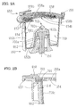
- Fig. 2A is a partially sectional perspective view of the centrifugal separator 650
- Fig. 2B is an enlarged view of an upper end face of the centrifugal separator 650.
- the centrifugal separator 650 includes a rotating shaft 651 and a substantially cylindrical dewatering drum 652 which is fixed to the rotating shaft 651.
- the dewatering drum 652 is made to open at an upper end thereof and has a shape in which a circumference of the drum is increased as the drum extends upwards.
- the rotating shaft 651 is disposed at a central portion of the dewatering drum 652.
- a protuberance 652a which is raised higher than a peripheral portion is formed at a central portion of a bottom surface 652b of the dewatering drum 651.
- the protuberance 652a is formed in such a manner as to extend to approximately one half the height of the dewatering drum.
- the rotating shaft 651 extends as deep as an interior of the protuberance 652a.
- the protuberance 652a By the protuberance 652a being so formed, the height of a center of gravity of the dewatering drum 652 becomes higher than a case where a bottom portion of the dewatering drum 652 has a uniform height, the stability of the dewatering drum 652 while it is rotating being thereby increased.
- the protuberance 652 does not necessarily have to be formed, and hence, the bottom surface 652b of the dewatering drum 652 may be formed flat.
- a driving motor 653 is disposed below the dewatering drum 652, and the rotating shaft 651 is rotated by the driving motor 653.
- a processing refuse container 700 which enables the removal of processing refuse is placed removably in the interior of the dewatering drum 652.
- the configuration of the processing refuse container 700 will be described in detail later.
- An annular filter 654 is disposed at an upper portion of the dewatering drum 652 for filtering out grinding water from discharged water containing processing refuse so as to promote the dewatering efficiency of processing refuse.
- the filter 654 has a filtering function to allow the passage of grinding water while preventing the passage of processing refuse of the order of 15 ⁇ m or larger in order to make filtered grinding water substantially clear in appearance.
- the filter 654 is made up a nonwoven fabric and preferably has an air permeability of 60 to 110 (cm 3 /cm 2 ⁇ sec).
- lock mechanisms 659 are provided in three locations on an edge portion 657 of the dewatering drum 652 which expands radially outwards from an upper portion of the dewatering drum 652.
- levers 659b of the lock mechanisms 659 being rotated counterclockwise, as is shown in Fig. 2B , the lid member 658 is fixed to the dewatering drum 652 by the lock mechanisms 659 in such a state that the filter 654 and a flange portion 701 of the container 700 are held between the lid member 658 and the edge portion 657 of the dewatering drum 652.
- the lock mechanism 659 is made up of a screw or the like which can be rotated manually by an operator, and a known mechanism can be adopted therefor.
- an upper cover 640a is attached to an upper portion (above the lid member 658 of the dewatering drum 652) of the housing 640 which accommodates therein the centrifugal separator 650 in such a manner as to be opened and closed.
- the drainpipe 3a extending from the apparatus main body 1 is connected to the drainpipe 641 attached to the upper cover 640a.
- the drainpipe 641 is positioned at a rotational center of the centrifugal separator 650 and has such a length that the drain pipe 641 passes through a central opening 658b formed through the lid member 658 and a central opening 654b formed through the filter 654 so as to extend as far as an interior of the centrifugal separator 652.
- the opening 658b of the lid member 658 and the opening 654b of the filter 654 are formed to have substantially the same diameter and are formed larger diametrically than outside diameter of the drainpipe 641. With this configuration, a gap 656 for allowing the escape of grinding water is formed between center-side ends of the lid member 658 and the filter 654 and the drainpipe 641.
- a lower opening of the drainpipe 641 is disposed in such a manner as to cover the protuberance 652a from thereabove, whereby discharged water flowing downwards through an upper portion of the drainpipe 641 bounces against the protuberance 652a and is directed downwards, so that grinding water is easily subjected to centrifugal action, and processing refuse are built up efficiently within the dewatering drum 652.
- the upper cover 640a also functions as a member which receives water drained from the filter 654, as well as water caused to splash from the gap 656 formed between the filter 641 and the lid member 658 and the drainpipe 641 so as to direct them downwards.
- a water collecting case 642 is provided on the outside of the dewatering drum 652 in such a manner as to surround the dewatering drum 652. Water received by the water collecting case 642 is led to the tank 630 by way of a pipe 643.
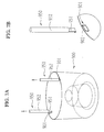
- FIG. 3A is a perspective view of the container 700 and the jig 750. In Fig. 3A , the container 700 is depicted as being partially cutaway.
- the container 700 has an external shape which resembles an interior shape of the dewatering drum 652. Namely, the container 700 has a side wall portion 700c, a bottom portion 700b and a protuberant portion 700a whose shapes match an inner side surface 652c, the bottom surface 652b and the protuberance 652a, respectively. However, an outside diameter of the side wall portion 700c is formed slightly smaller than an inside diameter of the inner side surface of the dewatering drum 652.
- An outer circumference of the side wall portion 700c is preferably formed to a size which ensures a slight gap ⁇ d (for example, a width of the order of 0.5 mm) that is formed between the inner side surface 652c of the dewatering drum 652 and itself when the container 700 is disposed in the interior of the dewatering drum 652 (refer to Fig. 2B ).
- a slight gap ⁇ d for example, a width of the order of 0.5 mm
- This gap ⁇ d is set to a dimension such that even in the event that the container 700 is subjected to a slight thermal expansion due to a change in ambient atmosphere, the container 700 is prevented from being brought into close contact with the inner side surface 652c of the dewatering drum 652, whereas even in the event that the container 700 is subjected to a slight thermal contraction due to a change in ambient atmosphere, the container 700 is prevented from getting loosened largely in the interior of the dewatering drum 652 so as not to produce vibrations while the dewatering drum 652 is rotating.
- the gap ⁇ d By the gap ⁇ d being ensured, frictional resistance is reduced that would otherwise be produced between the inner side surface 652c of the dewatering drum 652 and the container 700, thereby making it possible to easily lift up the container 700 in which processing refuse are built up.
- the placing operation is made easy.
- the center of gravity of the container 700 is made to coincide substantially with a rotational axis of the dewatering drum 652.
- the gap ⁇ d is preferably formed in a range of 0.2 to 1.0 mm (namely, when expressing the gap ⁇ d based on a difference between the inside diameter of the inner side surface 652c of the dewatering drum 652 and the outside diameter of the side wall portion 700c, the gap ⁇ d is in a range of 0.4 to 2.0 mm in diameter).
- the gap ⁇ d is smaller than 0.2 mm, the degree of friction due to contact between the inner side surface 652c of the dewatering drum 652 and the side wall portion 700c of the container 700 is increased, resulting in a large force being required in removing the container 700 in which processing refuse are accumulated from the dewatering drum 652.
- the gap ⁇ d is larger than 1.0 mm, the eccentricity G of the container with respect to the rotational center of the dewatering drum 652 becomes large, resulting in abnormal vibrations being increased while the dewatering drum 652 is rotating. Note that the gap ⁇ d is also formed between the protuberance 652a of the dewatering drum 652 and the protuberant portion 700a of the container 700.
- the container 700 is formed integrally of a resin such as polypropylene, ABS (acrylonitrile/butadiene/ styrene), polystyrene and polycarbonate, for example.
- the side wall portion 700c of the container 700 is formed with a thickness t which ensures a strength good enough to maintain the shape thereof even when the side wall portion 700c is subjected to a load resulting from a centrifugal force produced when the dewatering drum 652 is rotated.
- the container 700 of the grinding water and processing refuse disposal apparatus 3 is formed with a thickness of 0.8 mm.
- the container 700 preferably has a thickness of 0.3 to 4.0 mm.
- the thickness t is preferably 4.0 mm or thinner.
- the flange portion 701 extended radially outwards is provided integrally on an upper peripheral edge of the side wall portion 700c.
- the flange portion 701 is held together with the filter 654 by the dewatering drum 652 and the lid member 658 and is fixed in place by the lock mechanisms 659. Because of this, when the dewatering drum 652 is rotating, not only can the loosening of the container 700 be suppressed, but also the container 700 is allowed to rotate together with the dewatering drum 652.
- An annular projecting portion 703 is provided on an upper surface of the flange portion 701. A radial width of the projecting portion 703 is formed smaller than a radial width of the flange portion 701.
- the lid member 658 and the filter 654 are press fitted to each other by the projecting portion 703 (refer to Fig. 2B ). Namely, by the filter 654 being held between the projecting portion 703 and the lid member 658 to thereby be collapsed, the filter 654 also functions as a packing for preventing grinding water from flowing from a gap between the container 700 and the lid member 658. With this configuration, the flow of grinding water which is discharged through the filter 654 into the gap ⁇ d is suppressed as much as possible during centrifugal separation.
- Minute processing refuse which cannot be filtered out by the filter 654 are contained in grinding water, and in the event that such grinding water is allowed to flow in between the dewatering drum 652 and the container 700, fine processing refuse are allowed to remain in the dewatering drum 652 even after the removal of the container 700. In the event that the amount of processing refuse allowed to so remain is increased, those processing refuse then come to disturb the insertion of the container 700 into the dewatering drum 652 when the former is attempted to be inserted into the latter. With this configuration, since grinding water is prevented from flowing into the gap ⁇ d, labor hours required to clean the dewatering drum 652 after the removal of the container 700 are reduced remarkably.
- the flange portion 701 protruding radially outwards from the side wall portion 700c is formed to have a width of 10 mm
- the projecting portion 703 is formed to have a radial width of 1 mm.
- the projecting portion 703 is formed to have a height of 1 mm.
- the filter 654 is collapsed to 2 mm in thickness by the flange portion 701 and the lid member 658 and is further compression collapsed to 1 mm in thickness by being press fitted by the projecting portion 703 and the lid member.
- the filter 654 In the event that the filter 654 is collapsed to 1 mm in thickness, almost no grinding water which is scattered by centrifugal force is allowed to pass through the filter 654, whereby the filter 654 is allowed to function as the packing.
- the height of the projecting portion 703 can be changed in accordance with the thickness of the filter 654, in this case, in the event that the height of the projecting portion 703 is formed 1/2 to 1/3 of the thickness T of the filter 654, the filter 654 is allowed to be clogged.
- the radial width of the projecting portion 703 is preferably in a range of 0.8 mm to 3 mm.
- the radial width of the projecting portion 703 is less than 0.8 mm, the fabrication of the projecting portion 703 becomes difficult, and the strength thereof is not maintained.
- the lock mechanisms 659 need to apply a large magnitude of force to the lid member 658 in order to fix the lid member 658 to the dewatering drum 652, which requires the lock mechanisms 659 to be enlarged in size, and at this time, the operator is not allowed to simply operate the lock mechanisms 659 by operator's hand.
- the projecting portion 703 may be formed on a lower surface side of the lid member 658 in a position which corresponds to the flange portion 701 in place of the projecting portion 703 being formed on the flange portion 701 side of the container 700.
- the filter 654 is made to function as the packing, in a centrifugal separator in which no filter 654 is provided, a packing made of an annular elastic member may be provided in such a manner as to be held between the flange portion 701 and the lid member 658. By the packing being so provided, the flow of grinding water into the gap ⁇ d is prevented.
- a removal jig 750 includes a holding portion 752 to be held by the hand of the operator and two hooks (hook members) 751 which are fixed to a distal end of a shaft 753 which extends from the holding portion 752.
- an engagement portion 702 to be caught by (which is brought into engagement with) the hooks 751 of the removal jig 750 is formed at an upper end of the protuberant portion 700a which is situated at the center of the container 700.
- the engagement portion 702 is made up of two holes 702a so as to match the hooks so provided.
- the operator hooks the hooks 751 in the engagement portion 702 and lifts up the removal jig 750 by holding the holding portion 752 to thereby remove the container 700 from the dewatering drum 652.
- the holding portion 752 being formed to have such a length that the holding portion 752 is situated further upwards than an upper portion of the dewatering drum 652 when the hooks 751 are brought into engagement with the engagement portion 702, the operator is allowed to remove the container 700 from the dewatering drum 652 without touching processing refuse.
- distal end of the shaft 753 of the removal jig 750 may be formed into any shape, provided that it is constructed in such a manner as to be brought into engagement with the engagement portion 702 so that the container 700 can be lifted up, for example, a construction in which the engagement portion 702 is held by the distal end of the shaft 753.
- the engagement portion 702 may be disposed substantially at the center of the bottom surface 700b of the container 700. Processing refuse introduced into the container 700 is built up into an annular shape close to the side wall portion 700c side by virtue of rotation of the dewatering drum 652. Because of this, the engagement portion 702 is prevented from being buried under refuse, and the hooks 751 of the jig 750 can be hooked in the engagement portion 702.
- the operator does not necessarily have to use the jig 750 when attempting to remove the container 700 from the dewatering drum 625. This is because the operator can also lift up the container 700 by holding the engagement portion 702 by operator's fingers since the gap ⁇ d is provided in the way described above.
- the engagement portion 702 is formed into a substantially T-shape in section, and projecting portions 702b which project to both sides are made easy to be hooked by the fingers of the operator.
- There may be provided a single hole 702a which is formed into a shape which allows the entrance of a finger of the operator. Since processing refuse is not built up in the vicinity of the engagement portion 702 at the center of the container 700, the possibility of the hand of the operator getting dirty is reduced.
- the operator sets the container 700 in the interior of the dewatering drum 652.
- the operator can simply place the container 700 in the predetermined position in the interior of the dewatering drum 652 only by putting the container 700 in the dewatering drum 652 in such a manner as to follow the interior shape thereof.
- the operator places the filter 654 on the flange portion 701 of the container 700 and then places the lid member 658 on the filter 654. Thereafter, the operator fixes the lid member 658 using the lock mechanisms 659. At this time, the lid member and the filter 654 are press fitted together by the projecting portion 703. In this state, by inserting the drainpipe 641 attached to the upper cover 640a into the interior of the dewatering drum 652 (the container 700) through the openings of the lid member 658 and the filter 654, the preparation of the centrifugal separator 650 is completed.
- Water containing processing refuse from the processing apparatus main body 1 is caused to flow into the container 700 within the dewatering drum 652 through the drainpipe 641.
- discharged water is subjected to the influence of centrifugal force produced by the dewatering drum 652 so rotating.
- Refuse is forced towards the side wall portion 700c of the container 700 by virtue of the action of the centrifugal force and are then built up into an annular shape along the side wall portion 700c. Since the processing refuse is built up sequentially along the side wall portion 700c in a uniform fashion, the generation of vibrations is suppressed that would otherwise take place should processing refuse not be built up uniformly.
- a large amount of processing refuse is accumulated along the inner wall of the container 700 as a result of lenses being processed by the processing apparatus main body 1 repeatedly. Then, since when the amount of processing refuse so built up reaches or surpasses a certain level, the normal filtration becomes impossible, and the processing refuse so built up needs to be removed.
- the dewatering drum 652 is left rotating for a sufficient length of time even after the drainage of discharged water from the processing apparatus main body 1 is stopped, grinding water within the container 700 is forced to scatter to the outside of the container 700, the dewatering of processing refuse left within the container 700 is promoted.
- the operator unlocks the lock mechanisms 659, and after removing the lid member 658 and the filter 654, the operator removes the processing refuse so left in the container 700.
- Fig. 4 is an explanatory diagram explaining a refuse remove method. Processing refuse is accumulated into an annular shape in the interior of the container 700.
- the operator hooks the hooks 751 of the removal jig 750 in the engagement portion 702 and holds the holding portion 752 so as to lifts up the jig 750, whereby the operator can remove the container 700 from the dewatering drum 652 without getting operator's hand dirty. Alternately, the operator can hold directly the engagement portion 702 by one of operator's hands so as to remove the container 700.
- the container 700 is not closely attached to the dewatering drum 652 by the gap ⁇ b being provided between the dewatering drum 652 and the container 700, the operator can easily draw out the container 700 from the dewatering drum 652 without applying a large magnitude of force to the holding portion 752 of the jig 750 or the engagement portion 702 of the container 700.
- the container 700 being formed of a similar type of material (a resin such as polypropylene as described above) to eyeglass plastic lenses, the container 700 can be disposed of directly in a disposal bag together with processing refuse.
- Figs. 5A and 5B show a processing refuse container and a removal jig according to a modified example.
- Fig. 5A is a diagram showing the configuration of a refuse container 800 according to the modified example
- Fig. 5B is a diagram showing the configuration of a removal jig (a container removal jig) 860 according to the modified example.
- Engagement portions 802 in which distal end portions 861 of jigs 860 are to be hooked are provided on an upper end portion of a container 800 in two locations which are symmetrical across a rotational center of the container 800.
- An opening 803 into which the distal end portion of the jig 860 is inserted is provided in the engagement portion 802.
- the engagement portions 802 are described as being provided in the two locations, the engagement portions 802 may be provided in more than two locations, provided that the engagement portions 802 are disposed in positions which divide equally a circumference of the upper end face of the container 800 and that the center of gravity of the container 800 is situated in a position which constitutes a center position of the locations where the engagement portions 802 are so provided.
- the engagement portion 802 is constructed in such a manner as to be bent inwards of the container 800 by a hinge provided in a position which coincides with a side wall of the container 800.
- the distal end portion 861 of the removal jig 860 is allowed to be inserted into the opening 803.
- Restricting members 805 for restricting the rotation of the engagement portions 802 are provided on an inside of the container 800, whereby the sinking of the engagement portions 802 is prevented by the restricting members 805.
- the reason the engagement portions 802 are initially formed into a shape in which they project towards an outer circumferential side of the container 800 is that the engagement portions 802 can be molded integrally with the container 800 by a mold, and the engagement portions 802 may be configured in such a state that they are initially bent inwards of the container 800.
- the engagement portions 802 may be left projecting towards the outer circumferential side of the container 800, provided that portions for accommodating the engagement portions 802 are formed on the edge portion 657 side of the dewatering drum 652, so that the distal end portions 861 of the removal jig 860 can be inserted into the openings 803 in the engagement portions 802.
- the jig 860 is made up of a shaft 862 which is fabricated by a rod-like member, the distal end portion 861 which extends from the shaft 862, which is placed into the opening 803 and which constitutes a hook which is hooked in the opening 803, a grip (a grip portion) 863 which is formed by bending the shaft 862, and a support portion which is brought into abutment with the edge portion 657 of the dewatering drum 652.
- the distal end portion 861 is slightly bent upwards from an extension of the shaft 862 so as to be locked in the opening 803 easily when the distal end portion 861 is placed into the opening 803.
- the supporting portion 865 is provided on the shaft 862 in a position lying in the vicinity of the distal end portion 861, and the supporting portion 865 is brought into abutment with the edge portion 657 and supports the shaft 862, and an abutment portion 867 is provided at a lower end of an extension 866 which extends downwards from the shaft 862.
- the abutment portion 866 is brought into abutment with the edge portion 675 so as to constitute a fulcrum in the principle of leverage and the extension 866 plays a role of extending the fulcrum downwards.
- a cutout 869 is provided in the center of the extension 866, and the cutout 869 constitutes a locking portion for locking the container 800 when lifting up the container 800.
- FIG. 6 is an exemplary diagram of part of the periphery of the dewatering drum 652 which illustrates a state in which the container 800 is removed by the jig 860.
- Two jigs 860 are used so as to match the engagement portion 802 provided in the two locations.
- the jigs 860 When the distal end portions 861 of the jigs 860 are placed into the openings 803, the abutment portion 867 of the supporting portion 865 are brought into abutment with the edge portion 657. In this state, when the jigs 860 are caused to fall radially outwards, the container 800 in which processing refuse are built up is lifted upwards by virtue of a leverage action resulting from the cooperation of the jigs 860 with the edge portion 657.
- the jig 860 may be constructed to have hooks 751 which are the same as those shown in Fig. 3A , and at this time, the jigs 860 may be lifted up with the hooks 751 hooked in the openings 803.
- the operator may hold the two engagement portions 802 with the fingers of operator's left and right hands so as to remove the container 800 without using the jigs 860. Also, in this case, compared with a case where processing refuse are removed directly from the dewatering drum 652, the operator can remove the container 800 without getting operator's hands dirty to a large extent.
- Fig. 7A is a diagram showing the configurations of a refuse container and a removal jig according to another modified example.
- U-shaped engagement portions 901 are provided at an upper end of an inner side wall of a processing refuse container 900 in two locations which are symmetrical across a rotational center of the container.
- Fig. 7B is an enlarged view of one of the engagement portions 901.
- An opening 902 is formed by the inner side wall of the container 900 and the engagement portion 901 provided thereon.
- a jig 950 includes a rod-like holding portion 952 on which the operator grips with operator's hand and a hook 951 which is attached to a distal end of the holding portion 952 in such a manner as to extend therefrom.
- the hook 951 is hooked in the opening 902 in the engagement portion 901.
- the operator holds the two jigs 951 with operator's corresponding hands and forces the hooks 951 into the corresponding engagement portions 901 from outside so that the hooks 951 are hooked in the corresponding openings 902.
- the hooks 951 can be hooked in the openings 902.
- both the jigs 950 are gripped on and are then lifted upwards, whereby the operator can lift up the container 900 from the dewatering drum 652 without getting operator's hands dirty.
- the engagement portions 901 may be provided in three or more locations in place of being provided in the two locations as described above, provided that the center of gravity of the container 900 substantially coincides with a center of the engagement portions 901 so provided.
Landscapes
- Engineering & Computer Science (AREA)
- Mechanical Engineering (AREA)
- Chemical & Material Sciences (AREA)
- Ceramic Engineering (AREA)
- Inorganic Chemistry (AREA)
- Centrifugal Separators (AREA)
- Grinding-Machine Dressing And Accessory Apparatuses (AREA)
- Grinding And Polishing Of Tertiary Curved Surfaces And Surfaces With Complex Shapes (AREA)
Abstract
Description
- The present invention relates to a processing refuse disposal apparatus having a centrifugal separator for separating processing refuse from discharged grinding water has being used for processing eyeglass lenses.
- In processing a peripheral edge of an eyeglass lens, grinding water is supplied to a contact portion between a grinding wheel and a lens for cooling the contact portion. Processing refuse (waste) produced as a result of processing the peripheral edge of the lens is discharged from a grinding apparatus together with grinding water. As a method for disposing grinding water and processing refuse which are discharged from a grinding apparatus, there is known a centrifugal separator in which processing refuse is separated from grinding water by rotating a dewatering drum into which grinding water is introduced, and the grinding water is drained to the outside of the dewatering drum (
JP-2004-243452A JP-2002-283236A JP-2008-178969A - In the centrifugal separator, since when a large amount of processing refuse is accumulated in an interior of the dewatering drum, the filtering capability of the centrifugal separator is reduced, an operator is required to periodically remove the accumulated processing refuse from the dewatering drum. However, powder-like processing refuse agglomerate and build up in the dewatering drum, which causes a problem that the operator has to spend some time removing the processing refuse directly from the dewatering drum. Further, there is a problem in which a hand of the operator tends to get dirty by the processing refuse.
Although a method has been tried in which a plastic bag is placed in the dewatering drum, the plastic bag tends to wrinkle easily, and it is difficult to dispose the plastic bag within the dewatering drum uniformly. When the plastic bag wrinkles, processing refuse builds ununiformly, whereby abnormal vibrations are generated during rotation of the dewatering drum, and noise is increased. - The invention has been made in view of the problem inherent in the related-art processing refuse disposal apparatus, and a technical problem to be solved by the invention is to provide a processing refuse disposal apparatus which enables an easy removal of processing refuse from a dewatering drum of a centrifugal separator and which can suppress the generation of abnormal vibrations during rotation of the dewatering drum. Further, another technical problem to be solved by the invention is to provide a processing refuse disposal apparatus which can reduce the possibility of the hands of an operator getting dirty.
- With a view to solving the technical problems, the invention is characterized by having the following arrangement.
-
- (1) A processing refuse disposal apparatus for processing an eyeglass lens, the apparatus comprising:
- a centrifugal separator (650) including a dewatering drum (652) to which grinding water containing processing refuse is led from an eyeglass lens processing apparatus (1), a driving motor (653) for rotating the dewatering drum (652), and a filter (654); and
- a tank (630) for accumulating the grinding water passing through the filter,
characterized by
a processing refuse container (700, 800, 900) which is formed of resin and has a shape resembling a shape of side and bottom surfaces (652b, 652c) of an interior of the dewatering drum, the processing refuse container being placed in the interior of the dewatering drum,
wherein a side wall portion of the processing refuse container has a strength good enough to maintain the shape thereof when the dewatering drum in which the processing refuse container is placed is rotated.
- (2) The apparatus according to (1), characterized in that the processing refuse container is formed such that a gap in a range of 0.2 to 1.0 mm is formed between a side surface of the processing refuse container and a side surface of the interior of the dewatering drum.
- (3) The apparatus according to (2), characterized in that the processing refuse container includes, at a center bottom portion or an upper end portion thereof, an engagement portion (702, 802, 901) to be caught by a hook of a jig or a finger of an operator when the operator attempts to remove the processing refuse container from the dewatering drum.
- (4) The apparatus according to (1), characterized in that the processing refuse container is formed with a flange at an upper end portion thereof and is supported by the dewater drum by the flange.
-
-
Fig. 1 is an exemplary sectional view showing an eyeglass lens processing apparatus main body, a water supply mechanism and a filtering apparatus. -
Fig. 2A is a partially sectional perspective view of a centrifugal separator. -
Fig. 2B is an enlarged view of an upper end face of the centrifugal separator. -
Fig. 3A is a perspective view of a processing refuse container and a jig. -
Fig. 3B is a sectional view of an engagement portion of the processing refuse container. -
Fig. 4 is an explanatory diagram explaining a processing refuse remove method. -
Fig. 5A is a perspective view of a processing refuse container according to a modified example. -
Fig. 5B is an explanatory diagram of a removal jig for the processing refuse container shown inFig. 5A . -
Fig. 6 is an exemplary diagram explaining a state in which the processing refuse container is removed by the removal jig. -
Fig. 7A is a diagram showing the configurations of a processing refuse container and a removal jig according to another modified example. -
Fig. 7B is enlarged views of an upper end face of the processing refuse container and the removal jig which are shown inFig. 7A . - Hereinafter, an embodiment of the invention will be described based on the drawings.
Fig. 1 is an exemplary sectional view which depicts the configurations of an eyeglass lens processing apparatus main body, a water supply mechanism and a filtering apparatus.
A carriage portion is placed in an eyeglass lens processing apparatusmain body 1, and a peripheral edge of an eyeglass lens LE which is held by left and rightlens chuck shafts carriage 101 is brought into press contact with a grindingwheel 162 for processing. The grindingwheel 162 is made up of a rough grinding wheel for plastics and a finishing grinding wheel. The grindingwheel 162 is mounted on a grinding wheel spindle and is rotated by amotor 160. The lens LE is processed by the grindingwheel 162 by thelens chuck shafts carriage 101 being shifted vertically and horizontally based on processing data. A technique described in, for example,JP-A-2006-305698 main body 1 and a control for processing the lens LE. - A grinding water and processing
refuse disposal apparatus 3 having acentrifugal separator 650 and atank 630 for accumulating therein grinding water is disposed below the apparatusmain body 1. Discharged water containing grinding water used in the apparatusmain body 1 and processing refuse is led to thecentrifugal separator 650 via a dischargedwater drainpipe 3a. Anozzle 600 for injecting grinding water to a contact portion between thegrinding wheel 162 and the lens LE is disposed on a side wall of aprocessing chamber 20 disposed in an interior of the apparatusmain body 1. Discharged water containing processing refuse is introduced from adrain port 21 which is provided in a bottom side of the processing chamber 30 into thedrainpipe 3 for drainage. Atube 601 is connected to thenozzle 600, thetube 601 is connected to apump 602, and grinding water accumulated in thetank 630 is drawn by apump 602. - The
centrifugal separator 650 for separating grinding water and processing refuse from each other is disposed in an interior of ahousing 640 of thedisposal apparatus 3. The configuration of thecentrifugal separator 600 will be described with reference toFigs. 1 ,2A and 2B. Fig. 2A is a partially sectional perspective view of thecentrifugal separator 650, andFig. 2B is an enlarged view of an upper end face of thecentrifugal separator 650. - The
centrifugal separator 650 includes a rotatingshaft 651 and a substantially cylindrical dewateringdrum 652 which is fixed to the rotatingshaft 651. Thedewatering drum 652 is made to open at an upper end thereof and has a shape in which a circumference of the drum is increased as the drum extends upwards. Therotating shaft 651 is disposed at a central portion of thedewatering drum 652. Aprotuberance 652a which is raised higher than a peripheral portion is formed at a central portion of abottom surface 652b of thedewatering drum 651. Theprotuberance 652a is formed in such a manner as to extend to approximately one half the height of the dewatering drum. Therotating shaft 651 extends as deep as an interior of theprotuberance 652a. By theprotuberance 652a being so formed, the height of a center of gravity of thedewatering drum 652 becomes higher than a case where a bottom portion of thedewatering drum 652 has a uniform height, the stability of thedewatering drum 652 while it is rotating being thereby increased. In addition, in the event that the stability of thedewatering drum 652 while it is rotating is ensured, theprotuberance 652 does not necessarily have to be formed, and hence, thebottom surface 652b of thedewatering drum 652 may be formed flat. A drivingmotor 653 is disposed below thedewatering drum 652, and therotating shaft 651 is rotated by the drivingmotor 653. - A processing refuse
container 700 which enables the removal of processing refuse is placed removably in the interior of thedewatering drum 652. The configuration of the processing refusecontainer 700 will be described in detail later. Anannular filter 654 is disposed at an upper portion of thedewatering drum 652 for filtering out grinding water from discharged water containing processing refuse so as to promote the dewatering efficiency of processing refuse. Thefilter 654 has a filtering function to allow the passage of grinding water while preventing the passage of processing refuse of the order of 15 µm or larger in order to make filtered grinding water substantially clear in appearance. For example, thefilter 654 is made up a nonwoven fabric and preferably has an air permeability of 60 to 110 (cm3/cm2·sec). In the event that the air permeability surpasses 110 (cm3/cm2·sec), the turbidity of grinding water is increased, and bubbles are made easy to be produced within thetank 630 by such turbid grinding water being circulated. On the contrary, in the event that the air permeability is lowered below 60 (cm3/cm2·sec), thefilter 654 is made easy to be clogged by processing refuse, which decreases an amount of grinding water which can pass through thefilter 654, whereby the dewatering efficiency is decreased. A drainpipe 641 is passed through an upper side of thefilter 654, and anannular lid member 658 having a large number of slots or holes which allow the passage of grinding water is disposed on the upper side of thefilter 654. - In addition,
lock mechanisms 659 are provided in three locations on anedge portion 657 of thedewatering drum 652 which expands radially outwards from an upper portion of thedewatering drum 652. Bylevers 659b of thelock mechanisms 659 being rotated counterclockwise, as is shown inFig. 2B , thelid member 658 is fixed to thedewatering drum 652 by thelock mechanisms 659 in such a state that thefilter 654 and aflange portion 701 of thecontainer 700 are held between thelid member 658 and theedge portion 657 of thedewatering drum 652. When thelock mechanisms 659 are unlocked, thelid member 658 and thefilter 654 are made able to be removed from thedewatering drum 652, and further, the processing refusecontainer 700 is also made able to be removed from thedewatering drum 652. Note that in a simple configuration, thelock mechanism 659 is made up of a screw or the like which can be rotated manually by an operator, and a known mechanism can be adopted therefor. - In addition, in
Fig. 1 , anupper cover 640a is attached to an upper portion (above thelid member 658 of the dewatering drum 652) of thehousing 640 which accommodates therein thecentrifugal separator 650 in such a manner as to be opened and closed. Thedrainpipe 3a extending from the apparatusmain body 1 is connected to the drainpipe 641 attached to theupper cover 640a. The drainpipe 641 is positioned at a rotational center of thecentrifugal separator 650 and has such a length that the drain pipe 641 passes through acentral opening 658b formed through thelid member 658 and acentral opening 654b formed through thefilter 654 so as to extend as far as an interior of thecentrifugal separator 652. Theopening 658b of thelid member 658 and theopening 654b of thefilter 654 are formed to have substantially the same diameter and are formed larger diametrically than outside diameter of the drainpipe 641. With this configuration, agap 656 for allowing the escape of grinding water is formed between center-side ends of thelid member 658 and thefilter 654 and the drainpipe 641. - A lower opening of the drainpipe 641 is disposed in such a manner as to cover the
protuberance 652a from thereabove, whereby discharged water flowing downwards through an upper portion of the drainpipe 641 bounces against theprotuberance 652a and is directed downwards, so that grinding water is easily subjected to centrifugal action, and processing refuse are built up efficiently within thedewatering drum 652. Theupper cover 640a also functions as a member which receives water drained from thefilter 654, as well as water caused to splash from thegap 656 formed between the filter 641 and thelid member 658 and the drainpipe 641 so as to direct them downwards. Awater collecting case 642 is provided on the outside of thedewatering drum 652 in such a manner as to surround thedewatering drum 652. Water received by thewater collecting case 642 is led to thetank 630 by way of apipe 643. - Next, the configuration of the processing refuse container 70 and the configuration of a removal jig (a container removal jig) 750 which is used in removing the
refuse container 700 from thedewatering drum 652 will be described.Fig. 3A is a perspective view of thecontainer 700 and thejig 750. InFig. 3A , thecontainer 700 is depicted as being partially cutaway. - The
container 700 has an external shape which resembles an interior shape of thedewatering drum 652. Namely, thecontainer 700 has aside wall portion 700c, abottom portion 700b and aprotuberant portion 700a whose shapes match aninner side surface 652c, thebottom surface 652b and theprotuberance 652a, respectively. However, an outside diameter of theside wall portion 700c is formed slightly smaller than an inside diameter of the inner side surface of thedewatering drum 652. An outer circumference of theside wall portion 700c is preferably formed to a size which ensures a slight gap Δd (for example, a width of the order of 0.5 mm) that is formed between theinner side surface 652c of thedewatering drum 652 and itself when thecontainer 700 is disposed in the interior of the dewatering drum 652 (refer toFig. 2B ). This gap Δd is set to a dimension such that even in the event that thecontainer 700 is subjected to a slight thermal expansion due to a change in ambient atmosphere, thecontainer 700 is prevented from being brought into close contact with theinner side surface 652c of thedewatering drum 652, whereas even in the event that thecontainer 700 is subjected to a slight thermal contraction due to a change in ambient atmosphere, thecontainer 700 is prevented from getting loosened largely in the interior of thedewatering drum 652 so as not to produce vibrations while thedewatering drum 652 is rotating. By the gap Δd being ensured, frictional resistance is reduced that would otherwise be produced between theinner side surface 652c of thedewatering drum 652 and thecontainer 700, thereby making it possible to easily lift up thecontainer 700 in which processing refuse are built up. In addition, also when placing thecontainer 700 in the interior of thedewatering drum 652, the placing operation is made easy. The center of gravity of thecontainer 700 is made to coincide substantially with a rotational axis of thedewatering drum 652. - The gap Δd is preferably formed in a range of 0.2 to 1.0 mm (namely, when expressing the gap Δd based on a difference between the inside diameter of the
inner side surface 652c of thedewatering drum 652 and the outside diameter of theside wall portion 700c, the gap Δd is in a range of 0.4 to 2.0 mm in diameter). In the event that the gap Δd is smaller than 0.2 mm, the degree of friction due to contact between theinner side surface 652c of thedewatering drum 652 and theside wall portion 700c of thecontainer 700 is increased, resulting in a large force being required in removing thecontainer 700 in which processing refuse are accumulated from thedewatering drum 652. On the contrary, in the event that the gap Δd is larger than 1.0 mm, the eccentricity G of the container with respect to the rotational center of thedewatering drum 652 becomes large, resulting in abnormal vibrations being increased while thedewatering drum 652 is rotating. Note that the gap Δd is also formed between theprotuberance 652a of thedewatering drum 652 and theprotuberant portion 700a of thecontainer 700. - The
container 700 is formed integrally of a resin such as polypropylene, ABS (acrylonitrile/butadiene/ styrene), polystyrene and polycarbonate, for example. Theside wall portion 700c of thecontainer 700 is formed with a thickness t which ensures a strength good enough to maintain the shape thereof even when theside wall portion 700c is subjected to a load resulting from a centrifugal force produced when thedewatering drum 652 is rotated. For example, thecontainer 700 of the grinding water and processing refusedisposal apparatus 3 is formed with a thickness of 0.8 mm. When thecontainer 700 is formed of a resin such as polypropylene or ABS, thecontainer 700 preferably has a thickness of 0.3 to 4.0 mm. In the event that the thickness of thecontainer 700 is thinner than 0.3 mm, the shape of theside wall portion 700c cannot be maintained properly when thedewatering drum 652 is rotating, whereby the gap Δb described above becomes difficult to be ensured and theside wall portion 700c becomes easy to be broken. On the other hand, in the event that the thickness t becomes thicker than 0.3 mm, the strength is increased. However, in the event that the thickness t becomes too thick, thecontainer 700 becomes difficult to be molded integrally. In addition, in the event that the thickness t is too thick, an amount of processing refuse to be accumulated within thecontainer 700 is reduced, which is disadvantageous. With a view to facilitating the integral molding of thecontainer 700, the thickness t is preferably 4.0 mm or thinner. - The
flange portion 701 extended radially outwards is provided integrally on an upper peripheral edge of theside wall portion 700c. Theflange portion 701 is held together with thefilter 654 by thedewatering drum 652 and thelid member 658 and is fixed in place by thelock mechanisms 659. Because of this, when thedewatering drum 652 is rotating, not only can the loosening of thecontainer 700 be suppressed, but also thecontainer 700 is allowed to rotate together with thedewatering drum 652. An annular projectingportion 703 is provided on an upper surface of theflange portion 701. A radial width of the projectingportion 703 is formed smaller than a radial width of theflange portion 701. When the lid member is attached, thelid member 658 and thefilter 654 are press fitted to each other by the projecting portion 703 (refer toFig. 2B ). Namely, by thefilter 654 being held between the projectingportion 703 and thelid member 658 to thereby be collapsed, thefilter 654 also functions as a packing for preventing grinding water from flowing from a gap between thecontainer 700 and thelid member 658. With this configuration, the flow of grinding water which is discharged through thefilter 654 into the gap Δd is suppressed as much as possible during centrifugal separation. Minute processing refuse which cannot be filtered out by thefilter 654 are contained in grinding water, and in the event that such grinding water is allowed to flow in between thedewatering drum 652 and thecontainer 700, fine processing refuse are allowed to remain in thedewatering drum 652 even after the removal of thecontainer 700. In the event that the amount of processing refuse allowed to so remain is increased, those processing refuse then come to disturb the insertion of thecontainer 700 into thedewatering drum 652 when the former is attempted to be inserted into the latter. With this configuration, since grinding water is prevented from flowing into the gap Δd, labor hours required to clean thedewatering drum 652 after the removal of thecontainer 700 are reduced remarkably. - In this embodiment, the
flange portion 701 protruding radially outwards from theside wall portion 700c is formed to have a width of 10 mm, and the projectingportion 703 is formed to have a radial width of 1 mm. The projectingportion 703 is formed to have a height of 1 mm. In the case of the thickness of thefilter 654 which is made of a nonwoven fabric being 3 mm, thefilter 654 is collapsed to 2 mm in thickness by theflange portion 701 and thelid member 658 and is further compression collapsed to 1 mm in thickness by being press fitted by the projectingportion 703 and the lid member. In the event that thefilter 654 is collapsed to 1 mm in thickness, almost no grinding water which is scattered by centrifugal force is allowed to pass through thefilter 654, whereby thefilter 654 is allowed to function as the packing. Although the height of the projectingportion 703 can be changed in accordance with the thickness of thefilter 654, in this case, in the event that the height of the projectingportion 703 is formed 1/2 to 1/3 of the thickness T of thefilter 654, thefilter 654 is allowed to be clogged. In addition, the radial width of the projectingportion 703 is preferably in a range of 0.8 mm to 3 mm. In the event that the radial width of the projectingportion 703 is less than 0.8 mm, the fabrication of the projectingportion 703 becomes difficult, and the strength thereof is not maintained. On the contrary, in the event that the radial width surpasses 3 mm, thelock mechanisms 659 need to apply a large magnitude of force to thelid member 658 in order to fix thelid member 658 to thedewatering drum 652, which requires thelock mechanisms 659 to be enlarged in size, and at this time, the operator is not allowed to simply operate thelock mechanisms 659 by operator's hand. - Note that the projecting
portion 703 may be formed on a lower surface side of thelid member 658 in a position which corresponds to theflange portion 701 in place of the projectingportion 703 being formed on theflange portion 701 side of thecontainer 700. Although thefilter 654 is made to function as the packing, in a centrifugal separator in which nofilter 654 is provided, a packing made of an annular elastic member may be provided in such a manner as to be held between theflange portion 701 and thelid member 658. By the packing being so provided, the flow of grinding water into the gap Δd is prevented. - In
Fig. 3A , aremoval jig 750 includes a holdingportion 752 to be held by the hand of the operator and two hooks (hook members) 751 which are fixed to a distal end of ashaft 753 which extends from the holdingportion 752. On the other hand, anengagement portion 702 to be caught by (which is brought into engagement with) thehooks 751 of theremoval jig 750 is formed at an upper end of theprotuberant portion 700a which is situated at the center of thecontainer 700. In this embodiment, since theremoval jig 750 includes the twohooks 751, theengagement portion 702 is made up of twoholes 702a so as to match the hooks so provided. When the operator attempts to remove thecontainer 700 from thedewatering drum 652, the operator hooks thehooks 751 in theengagement portion 702 and lifts up theremoval jig 750 by holding the holdingportion 752 to thereby remove thecontainer 700 from thedewatering drum 652. By the holdingportion 752 being formed to have such a length that the holdingportion 752 is situated further upwards than an upper portion of thedewatering drum 652 when thehooks 751 are brought into engagement with theengagement portion 702, the operator is allowed to remove thecontainer 700 from thedewatering drum 652 without touching processing refuse. Note that the distal end of theshaft 753 of theremoval jig 750 may be formed into any shape, provided that it is constructed in such a manner as to be brought into engagement with theengagement portion 702 so that thecontainer 700 can be lifted up, for example, a construction in which theengagement portion 702 is held by the distal end of theshaft 753. - Also in a construction in which the
protuberant portion 700a is not formed in thecontainer 700, theengagement portion 702 may be disposed substantially at the center of thebottom surface 700b of thecontainer 700. Processing refuse introduced into thecontainer 700 is built up into an annular shape close to theside wall portion 700c side by virtue of rotation of thedewatering drum 652. Because of this, theengagement portion 702 is prevented from being buried under refuse, and thehooks 751 of thejig 750 can be hooked in theengagement portion 702. When processing refuse are disposed of, since thehooks 751 of thejig 750 are attached to theengagement portion 702 which lies at the center of thecontainer 700 where refuse are not built up, the attaching work of the jig to the engagement portion becomes simple, and the hand of the operator is prevented from getting dirty when processing refuse are disposed of. - The operator does not necessarily have to use the
jig 750 when attempting to remove thecontainer 700 from the dewatering drum 625. This is because the operator can also lift up thecontainer 700 by holding theengagement portion 702 by operator's fingers since the gap Δd is provided in the way described above. As is shown inFig. 3B , theengagement portion 702 is formed into a substantially T-shape in section, and projectingportions 702b which project to both sides are made easy to be hooked by the fingers of the operator. There may be provided asingle hole 702a which is formed into a shape which allows the entrance of a finger of the operator. Since processing refuse is not built up in the vicinity of theengagement portion 702 at the center of thecontainer 700, the possibility of the hand of the operator getting dirty is reduced. - Next, a filtering operation of grinding water by the
centrifugal separator 650 which includes the above-described configuration and removal operation of processing refuse will be described. As an initial step of the preparation of thecentrifugal separator 650, the operator sets thecontainer 700 in the interior of thedewatering drum 652. At this time, since thecontainer 700 has the shape which resembles the interior shape of thedewatering drum 652 and the gap Δd is ensured, the operator can simply place thecontainer 700 in the predetermined position in the interior of thedewatering drum 652 only by putting thecontainer 700 in thedewatering drum 652 in such a manner as to follow the interior shape thereof. Next, the operator places thefilter 654 on theflange portion 701 of thecontainer 700 and then places thelid member 658 on thefilter 654. Thereafter, the operator fixes thelid member 658 using thelock mechanisms 659. At this time, the lid member and thefilter 654 are press fitted together by the projectingportion 703. In this state, by inserting the drainpipe 641 attached to theupper cover 640a into the interior of the dewatering drum 652 (the container 700) through the openings of thelid member 658 and thefilter 654, the preparation of thecentrifugal separator 650 is completed. - Water containing processing refuse from the processing apparatus
main body 1 is caused to flow into thecontainer 700 within thedewatering drum 652 through the drainpipe 641. When thedewatering drum 652 rotates, discharged water is subjected to the influence of centrifugal force produced by thedewatering drum 652 so rotating. Refuse is forced towards theside wall portion 700c of thecontainer 700 by virtue of the action of the centrifugal force and are then built up into an annular shape along theside wall portion 700c. Since the processing refuse is built up sequentially along theside wall portion 700c in a uniform fashion, the generation of vibrations is suppressed that would otherwise take place should processing refuse not be built up uniformly. Grinding water separated from processing refuse whose specific weight is heavy (processing refuse whose particle size is large) is pushed upwards along thecontainer 700 and is then filtered by thefilter 654. Grinding water that has been filtered by thefilter 654 is collected into thewater collecting case 642. In addition, water that is not filtered by thefilter 654 is forced to scatter from thegap 656 formed between thefilter 654 and the drainpipe 641 and is then received by thewater collecting case 642. Water within thewater collecting case 642 is led into thetank 630 via thepipe 643. Since an end portion of thefilter 654 is press fitted by the projectingportion 703 of thecontainer 700 and thelid member 658, grinding water which is pushed towards an outer circumferential side of thefilter 654 is restricted from flowing into the gap Δd, whereby the infiltration of grinding water and fine processing refuse into the interior of thedewatering drum 652 is suppressed. - A large amount of processing refuse is accumulated along the inner wall of the
container 700 as a result of lenses being processed by the processing apparatusmain body 1 repeatedly. Then, since when the amount of processing refuse so built up reaches or surpasses a certain level, the normal filtration becomes impossible, and the processing refuse so built up needs to be removed. In the event that thedewatering drum 652 is left rotating for a sufficient length of time even after the drainage of discharged water from the processing apparatusmain body 1 is stopped, grinding water within thecontainer 700 is forced to scatter to the outside of thecontainer 700, the dewatering of processing refuse left within thecontainer 700 is promoted. The operator unlocks thelock mechanisms 659, and after removing thelid member 658 and thefilter 654, the operator removes the processing refuse so left in thecontainer 700. -
Fig. 4 is an explanatory diagram explaining a refuse remove method. Processing refuse is accumulated into an annular shape in the interior of thecontainer 700. The operator hooks thehooks 751 of theremoval jig 750 in theengagement portion 702 and holds the holdingportion 752 so as to lifts up thejig 750, whereby the operator can remove thecontainer 700 from thedewatering drum 652 without getting operator's hand dirty. Alternately, the operator can hold directly theengagement portion 702 by one of operator's hands so as to remove thecontainer 700. At this time, since thecontainer 700 is not closely attached to thedewatering drum 652 by the gap Δb being provided between thedewatering drum 652 and thecontainer 700, the operator can easily draw out thecontainer 700 from thedewatering drum 652 without applying a large magnitude of force to the holdingportion 752 of thejig 750 or theengagement portion 702 of thecontainer 700. By thecontainer 700 being formed of a similar type of material (a resin such as polypropylene as described above) to eyeglass plastic lenses, thecontainer 700 can be disposed of directly in a disposal bag together with processing refuse. - In the above embodiment, while the
engagement portion 702 is provided in the substantially center position of thecontainer 700, the invention is not limited thereto. -
Figs. 5A and 5B show a processing refuse container and a removal jig according to a modified example.Fig. 5A is a diagram showing the configuration of arefuse container 800 according to the modified example, andFig. 5B is a diagram showing the configuration of a removal jig (a container removal jig) 860 according to the modified example. -
Engagement portions 802 in whichdistal end portions 861 ofjigs 860 are to be hooked are provided on an upper end portion of acontainer 800 in two locations which are symmetrical across a rotational center of thecontainer 800. Anopening 803 into which the distal end portion of thejig 860 is inserted is provided in theengagement portion 802. Here, although theengagement portions 802 are described as being provided in the two locations, theengagement portions 802 may be provided in more than two locations, provided that theengagement portions 802 are disposed in positions which divide equally a circumference of the upper end face of thecontainer 800 and that the center of gravity of thecontainer 800 is situated in a position which constitutes a center position of the locations where theengagement portions 802 are so provided. In this example, theengagement portion 802 is constructed in such a manner as to be bent inwards of thecontainer 800 by a hinge provided in a position which coincides with a side wall of thecontainer 800. By thecontainer 800 being placed in thedewatering drum 652 in such a state that theengagement portion 802 is bent inwards, thedistal end portion 861 of theremoval jig 860 is allowed to be inserted into theopening 803. Restrictingmembers 805 for restricting the rotation of theengagement portions 802 are provided on an inside of thecontainer 800, whereby the sinking of theengagement portions 802 is prevented by the restrictingmembers 805. After thecontainer 800 is placed in thedewatering drum 652, thefilter 654 and thelid member 658 are disposed on theengagement portion 802. - The reason the
engagement portions 802 are initially formed into a shape in which they project towards an outer circumferential side of thecontainer 800 is that theengagement portions 802 can be molded integrally with thecontainer 800 by a mold, and theengagement portions 802 may be configured in such a state that they are initially bent inwards of thecontainer 800. In addition, theengagement portions 802 may be left projecting towards the outer circumferential side of thecontainer 800, provided that portions for accommodating theengagement portions 802 are formed on theedge portion 657 side of thedewatering drum 652, so that thedistal end portions 861 of theremoval jig 860 can be inserted into theopenings 803 in theengagement portions 802. - In
Fig. 5B , thejig 860 is made up of ashaft 862 which is fabricated by a rod-like member, thedistal end portion 861 which extends from theshaft 862, which is placed into theopening 803 and which constitutes a hook which is hooked in theopening 803, a grip (a grip portion) 863 which is formed by bending theshaft 862, and a support portion which is brought into abutment with theedge portion 657 of thedewatering drum 652. Thedistal end portion 861 is slightly bent upwards from an extension of theshaft 862 so as to be locked in theopening 803 easily when thedistal end portion 861 is placed into theopening 803. The supportingportion 865 is provided on theshaft 862 in a position lying in the vicinity of thedistal end portion 861, and the supportingportion 865 is brought into abutment with theedge portion 657 and supports theshaft 862, and anabutment portion 867 is provided at a lower end of anextension 866 which extends downwards from theshaft 862. Although it will be described in detail later, theabutment portion 866 is brought into abutment with the edge portion 675 so as to constitute a fulcrum in the principle of leverage and theextension 866 plays a role of extending the fulcrum downwards. Acutout 869 is provided in the center of theextension 866, and thecutout 869 constitutes a locking portion for locking thecontainer 800 when lifting up thecontainer 800. - Next, a method will be described for removing the
container 800 from thedewatering drum 652 by the use of thejig 800.Fig. 6 is an exemplary diagram of part of the periphery of thedewatering drum 652 which illustrates a state in which thecontainer 800 is removed by thejig 860. Twojigs 860 are used so as to match theengagement portion 802 provided in the two locations. The operator grips on thegrips 863 of thejigs 860 with the left and right hands thereof so as to operate thejigs 860. When thedistal end portions 861 of thejigs 860 are placed into theopenings 803, theabutment portion 867 of the supportingportion 865 are brought into abutment with theedge portion 657. In this state, when thejigs 860 are caused to fall radially outwards, thecontainer 800 in which processing refuse are built up is lifted upwards by virtue of a leverage action resulting from the cooperation of thejigs 860 with theedge portion 657. Note that thejig 860 may be constructed to havehooks 751 which are the same as those shown inFig. 3A , and at this time, thejigs 860 may be lifted up with thehooks 751 hooked in theopenings 803. Of course, in this example, too, the operator may hold the twoengagement portions 802 with the fingers of operator's left and right hands so as to remove thecontainer 800 without using thejigs 860. Also, in this case, compared with a case where processing refuse are removed directly from thedewatering drum 652, the operator can remove thecontainer 800 without getting operator's hands dirty to a large extent. -
Fig. 7A is a diagram showing the configurations of a refuse container and a removal jig according to another modified example. In this example,U-shaped engagement portions 901 are provided at an upper end of an inner side wall of aprocessing refuse container 900 in two locations which are symmetrical across a rotational center of the container.Fig. 7B is an enlarged view of one of theengagement portions 901. Anopening 902 is formed by the inner side wall of thecontainer 900 and theengagement portion 901 provided thereon. Ajig 950 includes a rod-like holding portion 952 on which the operator grips with operator's hand and ahook 951 which is attached to a distal end of the holdingportion 952 in such a manner as to extend therefrom. Thehook 951 is hooked in theopening 902 in theengagement portion 901. When removing thecontainer 900, the operator holds the twojigs 951 with operator's corresponding hands and forces thehooks 951 into thecorresponding engagement portions 901 from outside so that thehooks 951 are hooked in the correspondingopenings 902. In addition, although processing refuse are accumulated on the peripheries of theengagement portions 901, by the processing refuse which are accumulated on the peripheries of theengagement portions 901 being scraped out by thehooks 951, thehooks 951 can be hooked in theopenings 902. When thehooks 951 are managed to be hooked in theopenings 902, both thejigs 950 are gripped on and are then lifted upwards, whereby the operator can lift up thecontainer 900 from thedewatering drum 652 without getting operator's hands dirty. Theengagement portions 901 may be provided in three or more locations in place of being provided in the two locations as described above, provided that the center of gravity of thecontainer 900 substantially coincides with a center of theengagement portions 901 so provided.
Claims (4)
- A processing refuse disposal apparatus for processing an eyeglass lens, the apparatus comprising:a centrifugal separator (650) including a dewatering drum (652) to which grinding water containing processing refuse is led from an eyeglass lens processing apparatus (1), a driving motor (653) for rotating the dewatering drum (652), and a filter (654); anda tank (630) for accumulating the grinding water passing through the filter,characterized by
a processing refuse container (700, 800, 900) which is formed of resin and has a shape resembling a shape of side and bottom surfaces (652b, 652c) of an interior of the dewatering drum, the processing refuse container being placed in the interior of the dewatering drum,
wherein a side wall portion of the processing refuse container has a strength good enough to maintain the shape thereof when the dewatering drum in which the processing refuse container is placed is rotated. - The apparatus according to claim 1, characterized in that the processing refuse container is formed such that a gap in a range of 0.2 to 1.0 mm is formed between a side surface of the processing refuse container and a side surface of the interior of the dewatering drum.
- The apparatus according to claim 2, characterized in that the processing refuse container includes, at a center bottom portion or an upper end portion thereof, an engagement portion (702, 802, 901) to be caught by a hook of a jig or a finger of an operator when the operator attempts to remove the processing refuse container from the dewatering drum.
- The apparatus according to claim 1, characterized in that the processing refuse container is formed with a flange at an upper end portion thereof and is supported by the dewater drum by the flange.
Applications Claiming Priority (1)
| Application Number | Priority Date | Filing Date | Title |
|---|---|---|---|
| JP2008256895A JP5317051B2 (en) | 2008-10-01 | 2008-10-01 | Processing waste disposal device for eyeglass lens processing |
Publications (2)
| Publication Number | Publication Date |
|---|---|
| EP2172303A1 true EP2172303A1 (en) | 2010-04-07 |
| EP2172303B1 EP2172303B1 (en) | 2012-05-16 |
Family
ID=41506413
Family Applications (1)
| Application Number | Title | Priority Date | Filing Date |
|---|---|---|---|
| EP20090012421 Active EP2172303B1 (en) | 2008-10-01 | 2009-09-30 | Eyeglass lens processing refuse disposal apparatus |
Country Status (2)
| Country | Link |
|---|---|
| EP (1) | EP2172303B1 (en) |
| JP (1) | JP5317051B2 (en) |
Cited By (2)
| Publication number | Priority date | Publication date | Assignee | Title |
|---|---|---|---|---|
| CN104548849A (en) * | 2015-01-04 | 2015-04-29 | 绍兴绿态环境科技有限公司 | Wastewater and waste gas integral treatment machine for edge polishing of spectacles |
| US20220220011A1 (en) * | 2021-01-14 | 2022-07-14 | Nidek Co., Ltd. | Grinding water treatment device for eyeglasses lens processing |
Families Citing this family (3)
| Publication number | Priority date | Publication date | Assignee | Title |
|---|---|---|---|---|
| CN106076661A (en) * | 2016-08-13 | 2016-11-09 | 安徽东至广信农化有限公司 | A kind of Full-automatic centrifugal device for glyphosate |
| KR102231821B1 (en) * | 2020-08-31 | 2021-03-24 | 이영길 | Filtration apparatus for water used in grinding glass lenses |
| JP7750026B2 (en) * | 2021-01-14 | 2025-10-07 | 株式会社ニデック | Grinding water treatment equipment for eyeglass lens processing |
Citations (6)
| Publication number | Priority date | Publication date | Assignee | Title |
|---|---|---|---|---|
| GB1398042A (en) * | 1972-06-09 | 1975-06-18 | Hein Lehmann Ag | Slotted sieve centrifuge basket assembly |
| US4302332A (en) * | 1979-07-06 | 1981-11-24 | Nishihara Environmental Sanitation Research Corp., Ltd. | Centrifugal thickener |
| JP2002283236A (en) | 2001-03-26 | 2002-10-03 | Megane Drug Co Ltd | Plastic lens grinding liquid distributing system |
| JP2004243452A (en) | 2003-02-13 | 2004-09-02 | Topcon Corp | Lens grinding system |
| JP2006305698A (en) | 2005-04-28 | 2006-11-09 | Nidek Co Ltd | Spectacle lens rim processing device |
| EP1894671A1 (en) * | 2006-08-31 | 2008-03-05 | Nidek Co., Ltd. | Apparatus of treating grinding water for processing periphery of eyeglass lens |
Family Cites Families (1)
| Publication number | Priority date | Publication date | Assignee | Title |
|---|---|---|---|---|
| JP4522162B2 (en) * | 2003-11-07 | 2010-08-11 | 株式会社トプコン | Grinding water treatment equipment for lens grinding equipment |
-
2008
- 2008-10-01 JP JP2008256895A patent/JP5317051B2/en active Active
-
2009
- 2009-09-30 EP EP20090012421 patent/EP2172303B1/en active Active
Patent Citations (7)
| Publication number | Priority date | Publication date | Assignee | Title |
|---|---|---|---|---|
| GB1398042A (en) * | 1972-06-09 | 1975-06-18 | Hein Lehmann Ag | Slotted sieve centrifuge basket assembly |
| US4302332A (en) * | 1979-07-06 | 1981-11-24 | Nishihara Environmental Sanitation Research Corp., Ltd. | Centrifugal thickener |
| JP2002283236A (en) | 2001-03-26 | 2002-10-03 | Megane Drug Co Ltd | Plastic lens grinding liquid distributing system |
| JP2004243452A (en) | 2003-02-13 | 2004-09-02 | Topcon Corp | Lens grinding system |
| JP2006305698A (en) | 2005-04-28 | 2006-11-09 | Nidek Co Ltd | Spectacle lens rim processing device |
| EP1894671A1 (en) * | 2006-08-31 | 2008-03-05 | Nidek Co., Ltd. | Apparatus of treating grinding water for processing periphery of eyeglass lens |
| JP2008178969A (en) | 2006-08-31 | 2008-08-07 | Nidek Co Ltd | Grinding water treatment device for peripheral processing of eyeglass lenses |
Cited By (3)
| Publication number | Priority date | Publication date | Assignee | Title |
|---|---|---|---|---|
| CN104548849A (en) * | 2015-01-04 | 2015-04-29 | 绍兴绿态环境科技有限公司 | Wastewater and waste gas integral treatment machine for edge polishing of spectacles |
| US20220220011A1 (en) * | 2021-01-14 | 2022-07-14 | Nidek Co., Ltd. | Grinding water treatment device for eyeglasses lens processing |
| US12304836B2 (en) * | 2021-01-14 | 2025-05-20 | Nidek Co., Ltd. | Grinding water treatment device for eyeglasses lens processing |
Also Published As
| Publication number | Publication date |
|---|---|
| EP2172303B1 (en) | 2012-05-16 |
| JP2010082779A (en) | 2010-04-15 |
| JP5317051B2 (en) | 2013-10-16 |
Similar Documents
| Publication | Publication Date | Title |
|---|---|---|
| EP2172303B1 (en) | Eyeglass lens processing refuse disposal apparatus | |
| US7152277B2 (en) | Filter assembly for cyclone type dust collecting apparatus of a vacuum cleaner | |
| JP7847877B2 (en) | A filter unit for filtering fine particles and a filter cage for use with the filter unit. | |
| US5935435A (en) | Paint can strainer | |
| WO2020200453A1 (en) | Filtering device and method for removing particles and fibers, in particular microfibers, from washing water in a washing drum | |
| CN116869402A (en) | Filtration devices and vacuum cleaners | |
| JP4522162B2 (en) | Grinding water treatment equipment for lens grinding equipment | |
| NZ322831A (en) | A filter cartridge and method | |
| US20100300494A1 (en) | Filter cartridge, and device and method for cleaning a filter cartridge | |
| KR100507061B1 (en) | A filter for washing machine | |
| JP3445829B2 (en) | Garbage processing equipment | |
| EP4729149A1 (en) | Filter assembly and washing machine including the same | |
| KR200443207Y1 (en) | Countertop Food Dewatering Device | |
| CN223517123U (en) | Treatment device for waste water generated in processing of black jade raw stone | |
| CN215543557U (en) | Dirty liquid recycling bin | |
| CN218221726U (en) | Waste gas recovery purification unit | |
| WO2024255154A1 (en) | Clothing treatment apparatus | |
| JP4699088B2 (en) | Grinding water treatment equipment for eyeglass lens grinding equipment | |
| KR200180003Y1 (en) | Grit chamber set up structure of grit chamber manhole | |
| CN214260945U (en) | A backflow prevention mechanical pulp treatment device | |
| CN214808966U (en) | Polyurethane resin filter equipment | |
| CN215157752U (en) | Dirty liquid recovery unit | |
| KR100930234B1 (en) | Dust collector of vacuum cleaner | |
| JP3034781U (en) | Drainer for garbage | |
| JP2006122848A (en) | Water treatment equipment |
Legal Events
| Date | Code | Title | Description |
|---|---|---|---|
| PUAI | Public reference made under article 153(3) epc to a published international application that has entered the european phase |
Free format text: ORIGINAL CODE: 0009012 |
|
| AK | Designated contracting states |
Kind code of ref document: A1 Designated state(s): AT BE BG CH CY CZ DE DK EE ES FI FR GB GR HR HU IE IS IT LI LT LU LV MC MK MT NL NO PL PT RO SE SI SK SM TR |
|
| AX | Request for extension of the european patent |
Extension state: AL BA RS |
|
| 17P | Request for examination filed |
Effective date: 20101006 |
|
| 17Q | First examination report despatched |
Effective date: 20110615 |
|
| GRAP | Despatch of communication of intention to grant a patent |
Free format text: ORIGINAL CODE: EPIDOSNIGR1 |
|
| GRAS | Grant fee paid |
Free format text: ORIGINAL CODE: EPIDOSNIGR3 |
|
| GRAA | (expected) grant |
Free format text: ORIGINAL CODE: 0009210 |
|
| AK | Designated contracting states |
Kind code of ref document: B1 Designated state(s): AT BE BG CH CY CZ DE DK EE ES FI FR GB GR HR HU IE IS IT LI LT LU LV MC MK MT NL NO PL PT RO SE SI SK SM TR |
|
| REG | Reference to a national code |
Ref country code: GB Ref legal event code: FG4D |
|
| REG | Reference to a national code |
Ref country code: CH Ref legal event code: EP |
|
| REG | Reference to a national code |
Ref country code: AT Ref legal event code: REF Ref document number: 557821 Country of ref document: AT Kind code of ref document: T Effective date: 20120615 |
|
| REG | Reference to a national code |
Ref country code: IE Ref legal event code: FG4D |
|
| REG | Reference to a national code |
Ref country code: DE Ref legal event code: R096 Ref document number: 602009006929 Country of ref document: DE Effective date: 20120719 |
|
| REG | Reference to a national code |
Ref country code: NL Ref legal event code: VDEP Effective date: 20120516 |
|
| REG | Reference to a national code |
Ref country code: LT Ref legal event code: MG4D Effective date: 20120516 |
|
| PG25 | Lapsed in a contracting state [announced via postgrant information from national office to epo] |
Ref country code: NO Free format text: LAPSE BECAUSE OF FAILURE TO SUBMIT A TRANSLATION OF THE DESCRIPTION OR TO PAY THE FEE WITHIN THE PRESCRIBED TIME-LIMIT Effective date: 20120816 Ref country code: FI Free format text: LAPSE BECAUSE OF FAILURE TO SUBMIT A TRANSLATION OF THE DESCRIPTION OR TO PAY THE FEE WITHIN THE PRESCRIBED TIME-LIMIT Effective date: 20120516 Ref country code: LT Free format text: LAPSE BECAUSE OF FAILURE TO SUBMIT A TRANSLATION OF THE DESCRIPTION OR TO PAY THE FEE WITHIN THE PRESCRIBED TIME-LIMIT Effective date: 20120516 Ref country code: PL Free format text: LAPSE BECAUSE OF FAILURE TO SUBMIT A TRANSLATION OF THE DESCRIPTION OR TO PAY THE FEE WITHIN THE PRESCRIBED TIME-LIMIT Effective date: 20120516 Ref country code: SE Free format text: LAPSE BECAUSE OF FAILURE TO SUBMIT A TRANSLATION OF THE DESCRIPTION OR TO PAY THE FEE WITHIN THE PRESCRIBED TIME-LIMIT Effective date: 20120516 Ref country code: CY Free format text: LAPSE BECAUSE OF FAILURE TO SUBMIT A TRANSLATION OF THE DESCRIPTION OR TO PAY THE FEE WITHIN THE PRESCRIBED TIME-LIMIT Effective date: 20120516 Ref country code: IS Free format text: LAPSE BECAUSE OF FAILURE TO SUBMIT A TRANSLATION OF THE DESCRIPTION OR TO PAY THE FEE WITHIN THE PRESCRIBED TIME-LIMIT Effective date: 20120916 |
|
| REG | Reference to a national code |
Ref country code: AT Ref legal event code: MK05 Ref document number: 557821 Country of ref document: AT Kind code of ref document: T Effective date: 20120516 |
|
| PG25 | Lapsed in a contracting state [announced via postgrant information from national office to epo] |
Ref country code: PT Free format text: LAPSE BECAUSE OF FAILURE TO SUBMIT A TRANSLATION OF THE DESCRIPTION OR TO PAY THE FEE WITHIN THE PRESCRIBED TIME-LIMIT Effective date: 20120917 Ref country code: SI Free format text: LAPSE BECAUSE OF FAILURE TO SUBMIT A TRANSLATION OF THE DESCRIPTION OR TO PAY THE FEE WITHIN THE PRESCRIBED TIME-LIMIT Effective date: 20120516 Ref country code: GR Free format text: LAPSE BECAUSE OF FAILURE TO SUBMIT A TRANSLATION OF THE DESCRIPTION OR TO PAY THE FEE WITHIN THE PRESCRIBED TIME-LIMIT Effective date: 20120817 Ref country code: HR Free format text: LAPSE BECAUSE OF FAILURE TO SUBMIT A TRANSLATION OF THE DESCRIPTION OR TO PAY THE FEE WITHIN THE PRESCRIBED TIME-LIMIT Effective date: 20120516 Ref country code: LV Free format text: LAPSE BECAUSE OF FAILURE TO SUBMIT A TRANSLATION OF THE DESCRIPTION OR TO PAY THE FEE WITHIN THE PRESCRIBED TIME-LIMIT Effective date: 20120516 |
|
| PG25 | Lapsed in a contracting state [announced via postgrant information from national office to epo] |
Ref country code: BE Free format text: LAPSE BECAUSE OF FAILURE TO SUBMIT A TRANSLATION OF THE DESCRIPTION OR TO PAY THE FEE WITHIN THE PRESCRIBED TIME-LIMIT Effective date: 20120516 |
|
| PG25 | Lapsed in a contracting state [announced via postgrant information from national office to epo] |
Ref country code: SK Free format text: LAPSE BECAUSE OF FAILURE TO SUBMIT A TRANSLATION OF THE DESCRIPTION OR TO PAY THE FEE WITHIN THE PRESCRIBED TIME-LIMIT Effective date: 20120516 Ref country code: DK Free format text: LAPSE BECAUSE OF FAILURE TO SUBMIT A TRANSLATION OF THE DESCRIPTION OR TO PAY THE FEE WITHIN THE PRESCRIBED TIME-LIMIT Effective date: 20120516 Ref country code: EE Free format text: LAPSE BECAUSE OF FAILURE TO SUBMIT A TRANSLATION OF THE DESCRIPTION OR TO PAY THE FEE WITHIN THE PRESCRIBED TIME-LIMIT Effective date: 20120516 Ref country code: CZ Free format text: LAPSE BECAUSE OF FAILURE TO SUBMIT A TRANSLATION OF THE DESCRIPTION OR TO PAY THE FEE WITHIN THE PRESCRIBED TIME-LIMIT Effective date: 20120516 Ref country code: AT Free format text: LAPSE BECAUSE OF FAILURE TO SUBMIT A TRANSLATION OF THE DESCRIPTION OR TO PAY THE FEE WITHIN THE PRESCRIBED TIME-LIMIT Effective date: 20120516 Ref country code: RO Free format text: LAPSE BECAUSE OF FAILURE TO SUBMIT A TRANSLATION OF THE DESCRIPTION OR TO PAY THE FEE WITHIN THE PRESCRIBED TIME-LIMIT Effective date: 20120516 Ref country code: NL Free format text: LAPSE BECAUSE OF FAILURE TO SUBMIT A TRANSLATION OF THE DESCRIPTION OR TO PAY THE FEE WITHIN THE PRESCRIBED TIME-LIMIT Effective date: 20120516 |
|
| PG25 | Lapsed in a contracting state [announced via postgrant information from national office to epo] |
Ref country code: IT Free format text: LAPSE BECAUSE OF FAILURE TO SUBMIT A TRANSLATION OF THE DESCRIPTION OR TO PAY THE FEE WITHIN THE PRESCRIBED TIME-LIMIT Effective date: 20120516 |
|
| PLBE | No opposition filed within time limit |
Free format text: ORIGINAL CODE: 0009261 |
|
| STAA | Information on the status of an ep patent application or granted ep patent |
Free format text: STATUS: NO OPPOSITION FILED WITHIN TIME LIMIT |
|
| 26N | No opposition filed |
Effective date: 20130219 |
|
| PG25 | Lapsed in a contracting state [announced via postgrant information from national office to epo] |
Ref country code: MC Free format text: LAPSE BECAUSE OF NON-PAYMENT OF DUE FEES Effective date: 20120930 Ref country code: ES Free format text: LAPSE BECAUSE OF FAILURE TO SUBMIT A TRANSLATION OF THE DESCRIPTION OR TO PAY THE FEE WITHIN THE PRESCRIBED TIME-LIMIT Effective date: 20120827 |
|
| REG | Reference to a national code |
Ref country code: DE Ref legal event code: R097 Ref document number: 602009006929 Country of ref document: DE Effective date: 20130219 |
|
| REG | Reference to a national code |
Ref country code: IE Ref legal event code: MM4A |
|
| PG25 | Lapsed in a contracting state [announced via postgrant information from national office to epo] |
Ref country code: IE Free format text: LAPSE BECAUSE OF NON-PAYMENT OF DUE FEES Effective date: 20120930 Ref country code: BG Free format text: LAPSE BECAUSE OF FAILURE TO SUBMIT A TRANSLATION OF THE DESCRIPTION OR TO PAY THE FEE WITHIN THE PRESCRIBED TIME-LIMIT Effective date: 20120816 |
|
| PG25 | Lapsed in a contracting state [announced via postgrant information from national office to epo] |
Ref country code: MT Free format text: LAPSE BECAUSE OF FAILURE TO SUBMIT A TRANSLATION OF THE DESCRIPTION OR TO PAY THE FEE WITHIN THE PRESCRIBED TIME-LIMIT Effective date: 20120516 |
|
| PG25 | Lapsed in a contracting state [announced via postgrant information from national office to epo] |
Ref country code: TR Free format text: LAPSE BECAUSE OF FAILURE TO SUBMIT A TRANSLATION OF THE DESCRIPTION OR TO PAY THE FEE WITHIN THE PRESCRIBED TIME-LIMIT Effective date: 20120516 |
|
| REG | Reference to a national code |
Ref country code: CH Ref legal event code: PL |
|
| PG25 | Lapsed in a contracting state [announced via postgrant information from national office to epo] |
Ref country code: LU Free format text: LAPSE BECAUSE OF NON-PAYMENT OF DUE FEES Effective date: 20120930 Ref country code: SM Free format text: LAPSE BECAUSE OF FAILURE TO SUBMIT A TRANSLATION OF THE DESCRIPTION OR TO PAY THE FEE WITHIN THE PRESCRIBED TIME-LIMIT Effective date: 20120516 |
|
| PG25 | Lapsed in a contracting state [announced via postgrant information from national office to epo] |
Ref country code: HU Free format text: LAPSE BECAUSE OF FAILURE TO SUBMIT A TRANSLATION OF THE DESCRIPTION OR TO PAY THE FEE WITHIN THE PRESCRIBED TIME-LIMIT Effective date: 20090930 Ref country code: CH Free format text: LAPSE BECAUSE OF NON-PAYMENT OF DUE FEES Effective date: 20130930 Ref country code: LI Free format text: LAPSE BECAUSE OF NON-PAYMENT OF DUE FEES Effective date: 20130930 |
|
| PG25 | Lapsed in a contracting state [announced via postgrant information from national office to epo] |
Ref country code: MK Free format text: LAPSE BECAUSE OF FAILURE TO SUBMIT A TRANSLATION OF THE DESCRIPTION OR TO PAY THE FEE WITHIN THE PRESCRIBED TIME-LIMIT Effective date: 20120516 |
|
| REG | Reference to a national code |
Ref country code: FR Ref legal event code: PLFP Year of fee payment: 8 |
|
| REG | Reference to a national code |
Ref country code: FR Ref legal event code: PLFP Year of fee payment: 9 |
|
| REG | Reference to a national code |
Ref country code: FR Ref legal event code: PLFP Year of fee payment: 10 |
|
| PGFP | Annual fee paid to national office [announced via postgrant information from national office to epo] |
Ref country code: DE Payment date: 20190917 Year of fee payment: 11 |
|
| REG | Reference to a national code |
Ref country code: DE Ref legal event code: R119 Ref document number: 602009006929 Country of ref document: DE |
|
| PG25 | Lapsed in a contracting state [announced via postgrant information from national office to epo] |
Ref country code: DE Free format text: LAPSE BECAUSE OF NON-PAYMENT OF DUE FEES Effective date: 20210401 |
|
| PGFP | Annual fee paid to national office [announced via postgrant information from national office to epo] |
Ref country code: GB Payment date: 20210825 Year of fee payment: 13 |
|
| GBPC | Gb: european patent ceased through non-payment of renewal fee |
Effective date: 20220930 |
|
| P01 | Opt-out of the competence of the unified patent court (upc) registered |
Effective date: 20230509 |
|
| PG25 | Lapsed in a contracting state [announced via postgrant information from national office to epo] |
Ref country code: GB Free format text: LAPSE BECAUSE OF NON-PAYMENT OF DUE FEES Effective date: 20220930 |
|
| PGFP | Annual fee paid to national office [announced via postgrant information from national office to epo] |
Ref country code: FR Payment date: 20250808 Year of fee payment: 17 |