EP2172162B1 - Combined frequency microwave ablation system und devices - Google Patents
Combined frequency microwave ablation system und devices Download PDFInfo
- Publication number
- EP2172162B1 EP2172162B1 EP09172188.6A EP09172188A EP2172162B1 EP 2172162 B1 EP2172162 B1 EP 2172162B1 EP 09172188 A EP09172188 A EP 09172188A EP 2172162 B1 EP2172162 B1 EP 2172162B1
- Authority
- EP
- European Patent Office
- Prior art keywords
- current density
- microwave
- antenna
- phase
- waveform
- Prior art date
- Legal status (The legal status is an assumption and is not a legal conclusion. Google has not performed a legal analysis and makes no representation as to the accuracy of the status listed.)
- Active
Links
- 238000002679 ablation Methods 0.000 title claims description 66
- 230000008859 change Effects 0.000 claims description 13
- 230000010363 phase shift Effects 0.000 claims description 6
- 238000005259 measurement Methods 0.000 claims description 3
- 210000001519 tissue Anatomy 0.000 description 41
- 238000000034 method Methods 0.000 description 16
- 230000035515 penetration Effects 0.000 description 15
- 230000005672 electromagnetic field Effects 0.000 description 11
- 239000000654 additive Substances 0.000 description 8
- 230000000996 additive effect Effects 0.000 description 8
- 230000005540 biological transmission Effects 0.000 description 7
- 230000003247 decreasing effect Effects 0.000 description 6
- 238000010438 heat treatment Methods 0.000 description 6
- 230000003595 spectral effect Effects 0.000 description 6
- 238000011282 treatment Methods 0.000 description 6
- 239000004020 conductor Substances 0.000 description 5
- 238000003780 insertion Methods 0.000 description 5
- 230000037431 insertion Effects 0.000 description 5
- 230000001052 transient effect Effects 0.000 description 5
- 230000003321 amplification Effects 0.000 description 4
- 238000003199 nucleic acid amplification method Methods 0.000 description 4
- 230000000704 physical effect Effects 0.000 description 4
- 206010028980 Neoplasm Diseases 0.000 description 3
- 239000012809 cooling fluid Substances 0.000 description 3
- 239000003989 dielectric material Substances 0.000 description 3
- 230000005670 electromagnetic radiation Effects 0.000 description 3
- 238000002955 isolation Methods 0.000 description 3
- 201000011510 cancer Diseases 0.000 description 2
- 230000006378 damage Effects 0.000 description 2
- 230000001419 dependent effect Effects 0.000 description 2
- 230000008021 deposition Effects 0.000 description 2
- 238000010586 diagram Methods 0.000 description 2
- 230000000694 effects Effects 0.000 description 2
- 230000001747 exhibiting effect Effects 0.000 description 2
- 230000000670 limiting effect Effects 0.000 description 2
- 239000000463 material Substances 0.000 description 2
- 238000002156 mixing Methods 0.000 description 2
- 230000002195 synergetic effect Effects 0.000 description 2
- 238000013019 agitation Methods 0.000 description 1
- 230000000712 assembly Effects 0.000 description 1
- 238000000429 assembly Methods 0.000 description 1
- 229910052454 barium strontium titanate Inorganic materials 0.000 description 1
- 210000000481 breast Anatomy 0.000 description 1
- 230000015271 coagulation Effects 0.000 description 1
- 238000005345 coagulation Methods 0.000 description 1
- 238000000576 coating method Methods 0.000 description 1
- 238000005094 computer simulation Methods 0.000 description 1
- 201000010099 disease Diseases 0.000 description 1
- 208000037265 diseases, disorders, signs and symptoms Diseases 0.000 description 1
- 235000012489 doughnuts Nutrition 0.000 description 1
- 230000009977 dual effect Effects 0.000 description 1
- 230000005684 electric field Effects 0.000 description 1
- 230000002349 favourable effect Effects 0.000 description 1
- 210000002216 heart Anatomy 0.000 description 1
- 238000009217 hyperthermia therapy Methods 0.000 description 1
- 230000000266 injurious effect Effects 0.000 description 1
- 230000001788 irregular Effects 0.000 description 1
- 230000002427 irreversible effect Effects 0.000 description 1
- 210000004185 liver Anatomy 0.000 description 1
- 210000005228 liver tissue Anatomy 0.000 description 1
- 208000007106 menorrhagia Diseases 0.000 description 1
- 238000012986 modification Methods 0.000 description 1
- 230000004048 modification Effects 0.000 description 1
- 230000003121 nonmonotonic effect Effects 0.000 description 1
- 210000000056 organ Anatomy 0.000 description 1
- 230000037368 penetrate the skin Effects 0.000 description 1
- 210000002307 prostate Anatomy 0.000 description 1
- 230000005855 radiation Effects 0.000 description 1
- 238000001959 radiotherapy Methods 0.000 description 1
- 230000002829 reductive effect Effects 0.000 description 1
- 230000004044 response Effects 0.000 description 1
- 230000008685 targeting Effects 0.000 description 1
- 238000002560 therapeutic procedure Methods 0.000 description 1
Images


Classifications
-
- A—HUMAN NECESSITIES
- A61—MEDICAL OR VETERINARY SCIENCE; HYGIENE
- A61B—DIAGNOSIS; SURGERY; IDENTIFICATION
- A61B18/00—Surgical instruments, devices or methods for transferring non-mechanical forms of energy to or from the body
- A61B18/18—Surgical instruments, devices or methods for transferring non-mechanical forms of energy to or from the body by applying electromagnetic radiation, e.g. microwaves
- A61B18/1815—Surgical instruments, devices or methods for transferring non-mechanical forms of energy to or from the body by applying electromagnetic radiation, e.g. microwaves using microwaves
Definitions
- the present invention relates generally to medical / surgical ablation systems for delivering microwave energy to tissue. More particularly, the present disclosure relates to the spectral frequency content of the energy delivered to tissue to achieve deep penetration of energy.
- Such types of cancer cells have been found to denature at elevated temperatures (which are slightly lower than temperatures normally injurious to healthy cells). These types of treatments, known generally as hyperthermia therapy, typically utilize electromagnetic radiation to heat diseased cells to temperatures above 41° C while maintaining adjacent healthy cells at lower temperatures to insure that irreversible cell destruction does not occur. Other procedures utilizing electromagnetic radiation to heat tissue also include ablation and coagulation of the tissue. Such microwave ablation procedures, e.g., such as those performed for menorrhagia, are typically performed to ablate and coagulate the targeted tissue to denature or kill the tissue. Many procedures and types of devices utilizing electromagnetic radiation therapy are known in the art. Such microwave therapy is typically used in the treatment of tissue and organs, such as the prostate, heart, and liver.
- One less invasive procedure generally involves the treatment of tissue (e.g., a tumor) underlying the skin via the use of microwave energy. While microwave energy is able to penetrate the skin to reach the underlying tissue, the depth of penetration is typically dependant on several factors such as the physical properties of the tissue, the type of ablation instrument used for ablation, the current density pattern generated by the ablation instrument and the rate of energy delivery to tissue, and the spectral content of the energy.
- the first factor the physical properties of the tissue, is determined by the target tissue to be ablated, (i.e., the cancerous tissue) and the healthy tissue surrounding the target tissue.
- the target tissue to be ablated i.e., the cancerous tissue
- the healthy tissue surrounding the target tissue i.e., the healthy tissue surrounding the target tissue.
- a clinician cannot control the size or shape of the target tissue, or the location of the target tissue in the patient's body, but a clinician can select the type and number of ablation instruments, adjust the amount of delivered power, adjust the rate of energy delivery and vary the spectral content of the microwave energy.
- the spectral content of the energy is fixed to a particular frequency, such as, for example, 915 MHz, 2450 MHz and 10 GHz.
- the spectral content of the microwave signal determines the current density along the antenna and the amount of microwave energy delivered to the surrounding medium typically determines the depth of energy penetration and the shape of the resulting ablation region. For example, it is well known that a device delivering energy at 10 GHz only penetrates tissue a few millimeters while a device delivering energy at 915 MHz may penetrate tissue several centimeters.
- the present disclosure overcomes disadvantages of delivering energy at a specific frequency by disclosing an electrosurgical system, device and methods to simultaneously delivery microwave energy at a plurality of microwave frequencies which may allow better control over energy delivery and deposition around the instrument, as well as potentially sensing or determining the ablation shape or completeness by using antenna matching at different spectral combinations.
- US2005205566 A1 , US4448198 A1 disclose systems similar to the present invention.
- a system for delivering energy includes a housing having an antenna attached to the distal end configured to receive a microwave signal and radiate energy at two or more wavelengths and a microwave generator operably connecting to the antenna that provides the microwave signal to the antenna.
- the microwave generator generates a combined microwave signal containing microwave energy having at least a first and a second wavelength.
- the at least a first and second wavelengths are both capable of creating resonance in the antenna.
- the system includes a first microwave signal generator that generates a first microwave signal at the first wavelength, a second microwave signal generator that generates a second microwave signal at the second wavelength and a signal mixer that combines the first and second microwave signals to generate the combined microwave signal.
- the first wavelength is related to a first frequency and the second wavelength is related to a harmonic of the first frequency.
- the harmonic may be a third or a fifth harmonic.
- the first frequency may be about 915 MHz.
- the system includes a phase shifter configured to shift the phase of one of the first and second microwave signals relative to each other. The phase shifter may shift the phase between the first and second microwave signals between about 0° and 360°.
- the system also includes an amplifier that amplifies at least one of the first and second microwave signals to a desired intermixing ratio.
- the mixing ratio may be between about 1:99 and 99:
- An amplifier is provided to amplify the combined microwave signal.
- the system may further include a processor configured to control a parameter of the first microwave signal, the second microwave signal or the combined signal.
- distal refers to the portion which is furthest from the user and the term “proximal” refers to the portion that is closest to the user.
- proximal refers to the portion that is closest to the user.
- terms such as “above”, “below”, “forward”, “rearward”, etc. refer to the orientation of the figures or the direction of components and are simply used for convenience of description.
- an microwave energy delivery apparatus such as a microwave antenna assembly
- the microwave antenna assemblies described herein allow for direct insertion into tissue and include a half-wave dipole antenna at the distal end.
- An microwave assembly for percutaneous insertion into tissue is described in U.S. Patent No. 6,878,147 to Prakash, issued on April 12, 2005 .
- One critical aspect of placement of a microwave energy delivery apparatus is determining the size and shape of the ablation area produced by the device and insuring that the target tissue is contained within this ablation area.
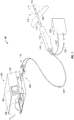
- Microwave ablation system 10 includes a combined frequency microwave generator 100 (hereinafter “microwave generator”) connected to a microwave energy delivery device 110 via a transmission line 120 and, in some embodiments, a cooling fluid supply 130.
- Microwave generator 100 includes a housing 130 that houses a microwave energy generation circuit 150 and a delivery device port 160 that connects to the device connector 170 of the transmission line 120.
- Microwave energy delivery device 110 includes a handle 112 and an elongate shaft 114 including an antenna 116 on the distal end. Distal portion of antenna 116 may form a sharpened tip 118 for percutaneous insertion into patient tissue 180. If present, a cooling fluid supply 130 supplies cooling fluid to microwave energy delivery device 110 via supply and return tubes 132, 134, respectively, connected to the proximal end of handle 112.
- Microwave energy delivery device 110 may be designed and intended for use with a conventional system that supplies microwave energy at a single microwave frequency or microwave energy delivery device may be specifically designed and intended for use with a combined frequency microwave generator 100. While the present disclosure describes a combined frequency microwave ablation system 10 and methods of use with a percutaneous type microwave energy delivery device, the systems and methods disclosed herewithin may be used with any suitable microwave energy delivery device 110 capable of delivering microwave energy, such as, for example, a catheter-type device, an endoscopic device and a surface delivery device (not shown).
- FIG. 2 is a transverse cross-sectional view of the distal end of a microwave energy delivery device 110 similar to the device of FIG. 1 .
- Antenna 216 is a conventional half-wave dipole microwave antenna.
- Antenna 216 includes a proximal radiating portion 216a connected to a feedline 220 at the proximal end thereof, and a distal radiating portion 216b.
- Sharpened tip 218 may be part of the distal radiating portion 216b or sharpened tip 218 may connect to distal radiating portion 216b and configured to not radiate energy.
- Antenna 216 comprises proximal radiating portion 216a and distal radiating portion 216b.
- Proximal radiating portion 216a may typically have an outer conductor 222 and an inner conductor 224, each of which extends along a longitudinal axis. Between the outer and inner conductors 222, 224 is typically a dielectric material 226 that is disposed longitudinally between the conductors 222, 224 to provide electrical isolation therebetween. Dielectric material 226 may constitute any number of appropriate materials, including air.
- Proximal and distal radiating portions 216a, 216b align at junction 216c, typically formed of a dielectric material. Junction 216c may be supported by inner conductor 224 that runs through junction 216c and at least partially extends into distal radiating portion 216b.
- a conventional system In use, a conventional system generates a microwave energy signal having a wavelength of ⁇ and transmits the signal through a transmission line 220 to antenna 216.
- Antenna 216 transmits energy from the proximal and distal radiating portions 216a, 216b.
- the radiating portions produce an electric field (hereinafter "E-field") in the surrounding medium which agitates and/or rotates H20 molecules (and other polar molecules) to produce heat.
- E-field electric field
- an E-field generated by the time-varying magnetic field, exerts a force on other electrically charged objects. While “E-fields” and “magnetic fields” are not the same, they cannot be completely separable. Therefore, for the sake of clarity the term “electromagnetic field” will be used to describe an E-field, a magnetic field or the combined forces generated by either an E-field or magnetic field.
- the electromagnetic field may produce localized movement of H20 molecules, i.e., vibrational and/or rotational movement, or the electromagnetic field may induce current flow over very short distances. This agitation, friction and/or induced current between molecules produces heat in the surrounding medium.
- the strength of the E-field at a given point is defined as the force that would be exerted on a charge at any given that point and the direction of the E-field is given by the direction of that force.
- the strength of the electromagnetic field may be represented by the current density (i.e., the measure of the density of a conserved charge) in the surrounding tissue. While current density is typically related to electric current, in the present disclosure current density generally represents the magnitude and relative strength of the electromagnetic field generated when a microwave signal is applied to the antenna.
- the physical length of the antenna 216 for efficient radiation of microwave energy may depend on several factors.
- One factor is the effective wavelength, ⁇ eff , which is dependent upon the dielectric properties of the surrounding medium.
- Antenna 216 through which microwave energy is transmitted at a wavelength, ⁇ may have differing effective wavelengths, ⁇ eff , depending upon the surrounding medium, e.g., liver tissue, as opposed to, e.g., breast tissue.
- coatings which may be disposed over antenna 216.
- a wavelength of the signal generated by the microwave generator and supplied to the antenna 216 is generically referenced as ⁇ , wherein the physical length of the antenna 216 is approximately about one-half the wavelength of the microwave signal, or ⁇ /2, and is the "effective' ⁇ of the antenna in the respective media.
- FIG. 3 is the half-wave di-pole antenna 216 of FIG. 2 , with a graphical illustration of the corresponding instantaneous current density 300 along the antenna 216 when supplied with a microwave signal at a wavelength of ⁇ .
- Antenna 216 includes proximal and distal radiating portions 216a, 216b with a sinusoidal current distribution across the antenna 216. The maximum current is at the center of the di-pole with zero current density at each end.
- the current density 300 is a representation of the instantaneous relative energy penetration in the surrounding medium related to the electromagnetic field patterns / waves radiated into surrounding tissue.
- antenna 216 illustrated in FIG. 3 is a balanced di-pole antenna wherein the proximal and distal radiating portions 216a, 216b are substantially equal
- the embodiments described herein may be implemented with an unbalanced di-pole antenna (wherein the proximal and distal radiating portions 216a, 216b are not equal.)
- Antenna 216 may also resonate and deliver energy to the surrounding medium when driven with signals containing additional wavelengths, wherein the wavelengths are odd multiple harmonics of ⁇ .
- a half-wave di-pole antenna with a physical length approximately equal to ⁇ /2 will also resonate with wavelengths of ⁇ , ⁇ 3rd 310 and ⁇ 5th 320, wherein ⁇ 3rd 310 and ⁇ 5th 320 are third and fifth harmonics of ⁇ , respectively.
- the physical length of the antenna is equal to ⁇ /2 for a wavelength of ⁇ 300, 3 ⁇ 3rd /2 for a wavelength of ⁇ 3rd 310 and 5 ⁇ 5th /2 for a wavelength of ⁇ 5th 320.
- the current densities for ⁇ 300, ⁇ 3rd 310 and ⁇ 5th 320 are sinusoidal in shape with ⁇ 300 having a single sinusoidal node, ⁇ 3rd having three sinusoidal nodes and ⁇ 5th 320 having five sinusoidal nodes.
- heating of the surrounding medium is dependant on the current density and the current density is similar in shape to the absolute value of the waveform 300, 310, 320.
- a microwave signal with a wavelength of ⁇ and a frequency of 915 MHz
- an antenna 216 with a physical length of approximately ⁇ /2 will generate current 300 in a sinusoidal distribution.
- the current 300 relates to the electromagnetic field and results in heating of the surrounding medium.
- the size of the resulting ablation area is related to the magnitude of the current 300 thus forming a circular ablation region.
- Ablation region may also be described as a donut or torus shaped region.
- an antenna 216 with a length of ⁇ /2 will also resonate and delivery energy into the surrounding medium when supplied with the third harmonic ⁇ 3rd 310 of ⁇ and the fifth harmonics ⁇ 5th 320 of ⁇ .
- an antenna that resonates at about 915 MHz, or ⁇ 300 will also resonate at about 2.525 GHz, or ⁇ 3rd , and at 4.209 GHz, or ⁇ 5th .
- the sine waves and other waveforms described herein relate to current density in a direction at a specific moment in time, wherein a portion of the waveform above the dipole provides the magnitude of the current moving to the right and a portion of the waveform below the dipole provides the magnitude of the current moving to the left.
- each ablation region may also be dependant on elements, such as, for example, the physical properties of the surrounding medium and the amount of energy delivered at each wavelength or harmonic.
- the microwave generator 100 of FIG. 1 supplies microwave energy to the microwave energy delivery device 110 at two or more frequencies wherein the two or more frequencies are resonant frequencies of the antenna 116.
- microwave generator may delivery energy with a first wavelength, such as, for example, ⁇ and a second wavelength, such as, for example, one or both ⁇ 3rd and ⁇ 5th .
- the frequencies may be selected to provide favorable resonance matching at one or more of the selected frequencies.
- an ablation procedure includes a microwave generator 100 for supplying energy at a first frequency such as, for example, 915 MHz, with a corresponding wavelength of ⁇ , for a first period of time, switching to a second frequency such as, for example 2.450 GHz, with a corresponding wavelength of ⁇ 3rd , for a second period of time and return to a first frequency for a third period of time.
- Microwave generator 100 may determine the best relationship between the two frequencies, frequency combinations and/or the duration of each delivery period (i.e., s-parameter relationship such as, for example, the S11, or input port voltage reflection coefficient, for each frequency).
- an ablation procedure includes a microwave generator 100 supplying energy at a first frequency for a first period of time, a second frequency for a second period of time and a third frequency for a third period of time.
- a measured parameter may be used to determine one or more of the delivered frequencies.
- the present invention relates to systems, devices and methods for combining resonant frequencies simultaneously during ablation in order to achieve deeper penetration or variably targeting of microwave energy.
- the direction of the currents generated by the antenna 216 are in the same direction.
- the direction of the currents generated by the antenna 216 changes with each half-cycle of the waveform. More specifically, at a wavelength of ⁇ 3rd the direction of the current changes at 310a and 310b and at a wavelength of ⁇ 5th the direction of the current changes at 320a, 320b, 320c and 320d.
- the new waveforms include areas where the two waveforms are additive thereby creating a synergistic effect resulting higher current density and greater tissue penetration.
- the new waveforms may also include areas where one waveform cancels at least a portion of the second waveform thereby creating areas of reduced energy delivery.
- the current generated by the three waveforms of ⁇ 300, ⁇ 3rd 310, and ⁇ 5th 320 is in the same direction, therefore combining any of the waveforms in this portion of the antenna 216 produces an additive affect.
- the waveforms for ⁇ and ⁇ 3rd are additive to each other and opposite in direction of waveform ⁇ 5th . Therefore, between position 320a and position 310a waveforms ⁇ and ⁇ 3rd are additive if combined and opposite in the direction of waveform ⁇ 5th and therefore would have a canceling effect.
- the waveforms for ⁇ 3rd and ⁇ 5th are additive to each other and opposite in direction of waveform ⁇ .
- the waveforms ⁇ 3rd and ⁇ 5th are additive if combined and opposite in direction of waveform ⁇ .
- Antenna, 216 when driven by a resonant waveform ⁇ , ⁇ 3rd or ⁇ 5th , generates an electromagnetic field including "far field" energy that results in a corresponding current density 300, 310 and 320 wherein the current density shape is illustrative of the energy distribution.
- the ablation region while related to the shape of the energy distribution, may not resemble the shape of the energy distribution due to dissipation of energy into the surrounding medium before reaching the area defined by the "far-field” region.
- the "far-field” may correspond to several centimeters outside of the ablation region.
- the shape of the "far-field" region and the resulting ablation region may be varied by changing the electromagnetic field during the ablation procedure. For example, changing the waveform between ⁇ , ⁇ 3rd or ⁇ 5th will change the shape of the electromagnetic field and the resulting ablation region.
- microwave generator 100 of FIG. 1 simultaneously delivers microwave energy at two different wavelengths to the microwave energy delivery device 110.
- Microwave generator 100 may select any one of the wavelengths to be delivered to the microwave energy delivery device 110, the intermixing ratio between the two frequencies (e.g., the ratio of energy supplied at each frequency) and the phase relationship, or phase angle, between the one or more signals.
- the wavelengths may be selected to create a desirable resultant current density pattern, desirable ablation pattern and/or desirable ablation region or shape.
- the resultant current density pattern may result in deep penetration of energy into the surrounding medium or may produce an ablation region with a desirable shape or volume.
- combining microwave signals with different wavelengths results in the generation of varying current densities and patterns.
- combining wavelengths of ⁇ and ⁇ 3rd may produce a current density pattern that provides deep penetration of energy into the surrounding medium at the proximal and distal ends of the antenna 216 and combining wavelengths of combining wavelengths of ⁇ and ⁇ 5th may produce a current density pattern that provides energy delivery to nodes at the midpoint and endpoints of the antenna 216.
- the clinician may select wavelengths that generate current density patterns that match the target region or area.
- At least one property of a microwave signal is selected to create a desirable current density pattern and/or resulting ablation region.
- the property may be the phase angle between the two microwave signals, the intensity ratio between the two signals, the energy delivered to the surrounding medium or any other suitable property.
- the current density pattern created by combining microwave signals with wavelengths of ⁇ and ⁇ 3rd and in phase results in a current density pattern that provides a concentration of current at the proximal and distal ends of the antenna 216 while combining microwave signals with wavelengths of ⁇ and ⁇ 3rd 180° out of phase results in concentration of current at the midpoint with smaller nodes at the proximal and distal ends of the antenna 216.
- At least one property of a microwave signal is adjusted to change the shape of a current density pattern created by combining the microwave signals.
- the current density pattern may be changed by shifting the phase relationship between the two signals from in phase to 180° out-of-phase or therebetween in phase and -180° out-of-phase.
- the phase relationship between the two signals may be initially selected to generate a desirable current density pattern and changed during an ablation procedure or during the delivery of energy in order to adjust the current density pattern, increase the size of ablation region or to adjust the shape of the ablation region.
- the property may relate to the intermixing ratio between the two microwave signals.
- the intermixing ratio between the first and second microwave signals may be initially set in a range from of 99:1 to 1:99.
- the intermixing ratio may be adjusted during the delivery of microwave energy to change the current density pattern or to change the overall shape and/or volume of the ablation region.
- the intermixing ratio may be adjusted to increase the energy delivered at a wavelength less susceptible to changes in the physical properties of the surrounding medium.
- FIG. 5 is a block diagram of the microwave energy generation circuit 150 of FIG. 1 for generating and combining microwave energy at two different wavelengths, according to the present invention.
- Microwave energy generation circuit 150 includes first and second microwave signal generators 152a, 152b, first and second phase shifters 154a, 154b, first and second signal amplifiers 156a, 156b, signal mixer 158 and a mixed signal amplifier circuit 159.
- Microwave energy generators and microwave generation circuits are generally known in the art, therefore, only those elements of a microwave energy generation circuit 150 specific to the present disclosure will be described in detail.
- First and second microwave signal generators 152a, 152b generate microwave signals at two wavelengths.
- first microwave signal generator 152a may produce a signal with a wavelength of ⁇ and second microwave signal generator 152b may producing a signal with a wavelength that is not equal or equivalent to ⁇ .
- first microwave signal generator 152a produces a signal at a resonant frequency of an antenna and the second microwave signal generator 152b may generate a signal at a harmonic of the resonant frequency.
- processor 151 monitors and/or controls the wavelength of the signal produced by first and second signal generators 152a, 152b.
- Processor 151 may provide one or more parameters, such as a first wavelength of ⁇ to the first signal generator 152a and a parameter, such as a second wavelength to the second signal generator 152b.
- One or more wavelengths are calculated by the processor 151, determined by a parameter of the microwave energy delivery device.
- a second wavelength may be a harmonic of the first wavelength ⁇ , such as, for example, the third harmonic ⁇ 3rd or fifth harmonic ⁇ 5th .
- Processor 151 may receive the first wavelength from a clinician and/or may calculate the ⁇ 3rd or ⁇ 5th therefrom.
- processor 151 includes an algorithm that calculates or adjusts the wavelength generated by first and/or second signal generators 152a, 152b.
- Mixed signal amplifier circuit 159 provides feedback (i.e., forward power and/or reflected power) to the processor 151 and processor 151 calculates or adjusts one or more properties of the generated signals.
- processor 151 determines a first resonant frequency by varying the wavelength ⁇ generated by the first microwave signal generator 152.
- the wavelength of the second microwave signal generator 153b is determined by a similar algorithm or may be calculated as a harmonic of the first wavelength, such as, for example ⁇ 3rd and ⁇ 5th .
- microwave energy generation circuit 150 includes first and second phase shifters 154a, 154b for delaying at least one signal thereby changing the phase angle between the signals from the first and second microwave signal generators 152a, 152b, i.e., phase-shifting the signals.
- the magnitude of the phase-shift between the signals from the first and second microwave signal generators 152a, 152b may be fixed, such as, for example, 180° apart, or processor 151 may dynamically adjust the amount of the phase-shift between the signals. Phase-shifting may be adjusted to vary the current density as described hereinbelow or to maintain resonance with the antenna (not explicitly shown).
- first and second phase shifters 154a, 154b provide low insertion loss, high power handling and instantaneous phase change response. Signal loss due to the first and second phase shifters 154a, 154b may be overcome by the amount of signal amplification of the first or second signal amplifiers 156a, 156b.
- First and second phase shifters 154a, 154b may be a switched line phase shifter, a loaded-line phase shifter, a ferroelectric phase shifter, a reflective phase shifter or any other suitable device that shifts the phase of a first microwave signal relative to a second microwave signal.
- First and second phase shifters 154a, 154b may be analog or digital and be controlled electrically, magnetically or mechanically.
- Analog phase shifters may provide variable phase shifting, such as, for example, a variable voltage that may be adjusted through hardware or electronically controlled.
- analog phase shifters 154a 154b may be controlled by capacitance such as, for example, a nonlinear dielectric such as barium strontium titanate, or a ferroelectric material.
- one or more phase shifters 154a, 154b may be a mechanically-controlled analog phase shifter constructed by selecting a mechanically lengthened the transmission path.
- Phase shifters 154a, 154b may be configured to lengthen a transmission path or may provide a plurality of transmission paths of varying length and be configured to select one of the plurality of transmission paths that provides the desired phase shift.
- the first microwave signal generator 152a may generate and supply a signal directly to the first signal amplifier 156a thereby bypassing and eliminating the first phase shifter 154a.
- the signal from the second microwave signal generator 152b may be phase shifted by the second phase shifter 154b relative to the signal from the first microwave signal generator 152a.
- a second signal amplifier 156b may amplify the single from the second phase shifter 154b to account for any signal loss in the second phase shifter 154b.
- First and second signal amplifiers 156a, 156b amplify the signals generated by the respective first and second microwave signal generators 152a, 152b. Signal amplification by the first and second signal amplifiers 156a, 156b may be performed prior to mixing or combining of the two signals by the signal mixer 158, to provide a suitable intermixing ratio between the two signals, as discussed hereinbelow.
- Processor 151 may adjust the intermixing ratio between the two signals to provide a desirable current density pattern. For example, processor 151 may initially provide a 3:1 intermixing ratio between the energy delivered at a first wavelength, ⁇ , to a second wavelength, ⁇ 3rd . As the medium heats and the impendence of the medium increases, the intermixing ratio may be adjusted to a second intermixing ratio, such as, for example, an intermixing ratio of 1:1, 1:3 or 1:99. The adjustment of the intermixing ratio may be changed stepwise or continuously.
- the intermixing ratio may be changed dynamically by the processor or the change may be changed based on feedback from the microwave generation circuit 150.
- the change in the intermixing ratio may be automatically performed by a hardwired circuit (not shown).
- the change may be initiated or selected by a clinician.
- the signals generated from the first and second signal generators 152a, 152b are combined by the signal mixer 158 and amplified by the mixed signal amplifier circuit 159.
- Signal mixer 158 receives a first signal, generated by the first microwave signal generator 152a on Port A and a second signal, generated by the second microwave signal generator 152b on Port B.
- Signal mixer 158 combines the signals received on Ports A and Port B and supplies the combined signal to the mixed signal amplifier circuit 159 through Port C.
- Signal mixer 158 may provide suitable isolation between Ports A and B while keeping the signals from Port A and Port be in phase (0° difference).
- Port A, Port B and/or Port C may provide 50 ohm nominal impedance or any other suitable or desirable impedance.
- Amplification of the mixed signal provided from Port C of the signal mixer 158 is performed by the mixed signal amplifier circuit 158.
- the amount of amplification, or the power level of the signal delivered to the delivery device port 160 is determined by the processor 151 or selected or entered by a clinician via the front panel 105 of the microwave generator of FIG. 1 .
- the power level of the signal delivered to the delivery device port 160 may be determined, calculated or selected by the microwave generator based on an energy delivery parameter or the procedure performed.
- Mixed signal amplifier circuit 150 typically includes one or more amplifiers including a power amplifier, a circulator or other suitable means of signal isolation and includes a dual directional coupler or other means to measure forward and/or reflective power or any other suitable signal measurement device.
- tissue impedance measuring tissue temperature measuring, current, voltage, power and energy measuring and phase of voltage and current measuring.
- the method disclosed herein may be carried out using a feedback system incorporated into an electrosurgical system or may be a stand-alone modular embodiment (e.g., removable modular circuit configured to be electrically coupled to various components, such as a generator, of the electrosurgical system).
- the current density patterns produced by an antenna when the antenna is driven with various resonant frequencies harmonics form different patterns of energy deposition along the antenna's length.
- the antenna when driven with energy at a single frequency, will form "hot spots" at one or more points along the antenna or in the surrounding medium wherein the location of the "hot spots” is related to a relative maximum or a maximum current density.
- the "hot spots" locations are dependant on whether the antenna is driven with a first, third or fifth order harmonic, generally fixed in location and may be predictable and/or calculated with a suitable computer simulation model.
- a resultant current density waveform formed by combining two or more waveforms, produces a resultant current density waveform current density pattern that is transient (i.e., the current density changes based on a relationship between the two or more waveforms at any point in time).
- the position of the maximum current density and the position of "hot spots" related to the maximum current density may not be constant and may change based on this relationship between the two or more waves.
- the resultant current density waveform and related current density pattern may be non-monotonic with a plurality of relative maximum current density maximums thereby resulting in a plurality of "hot spots", each related to a relative maximum or maximum current density.
- FIGS. 6A-6B further illustrates the changing current density pattern of the resultant current density waveform 330a-1.
- FIG. 6A is a plot of two waveforms, ⁇ 300 and ⁇ 3th 310, wherein ⁇ 3th 310 is the third harmonic of ⁇ 300 and ⁇ 300 and ⁇ 3rd 310 are "in phase" with each other.
- time is represented in the 'phase angle' of the ⁇ 300 waveform and the magnitude is normalized.
- FIG. 6 illustrates the two waveforms ⁇ 300and ⁇ 3th 310 from FIG. 6A and the current density pattern of the resultant current density waveform 330a-1 at a plurality of instantaneous points in time.
- the time interval is shifted by 30° thereby illustrating the change in the instantaneous current density pattern of the two waveforms 300a-1, 310a-1 and the resultant current density waveform 330a-1.
- Plots are normalized to the resonant frequency such that the 'ends' of the antenna are at 0 and 3.
- the current at the antenna 'ends' are idealized with a magnitude of zero. While the present embodiment illustrates a balanced dipole antenna the embodiments illustrated herewithin may be used with other types of antennas, such as, for example, an unbalanced dipole antenna.
- the resultant current density waveform 330b generated from ⁇ 300b and ⁇ 3th 310b produces three relative current density maximums.
- the waveform ⁇ 3th 310b is at its peak (at the feed point), the waveform ⁇ 300b is half of its peak with the current distributed across the dipole length.
- waveform ⁇ 3th 310c exhibits 'null' current along the antenna and the resultant current density waveform 330c is equal to waveform ⁇ 300c.
- the resultant current density waveform 330d generated from waveforms ⁇ 300d and ⁇ 3th 310d produces two relative current density maximums.
- the direction of current flow for both relative current density maximums is to the right.
- Both waveforms ⁇ 300d and ⁇ 3th 310d are at a peak, 180° out of phase thereby canceling at the feed point but not canceling along the dipole away from the feed point.
- waveform ⁇ 3th 310e exhibits 'null' current along the antenna and the resultant current density waveform 330e is equal to waveform ⁇ 300e.
- the resultant current density waveform 330f generated from ⁇ 300f and ⁇ 3th 310f produces three relative current density maximums.
- ⁇ 300g and ⁇ 3th 310g exhibit 'null' current along the antenna, resulting in a resultant current density waveform 330g also exhibiting 'null' current along the antenna.
- the resultant current density waveform 330h generated from ⁇ 300h and ⁇ 3th 310h produces three relative current density maximums.
- waveforms ⁇ 3th 310i exhibits 'null' current along the antenna and the resultant current density waveform 330i is equal to waveform ⁇ 300i.
- the resultant current density waveform 330j generated from waveforms ⁇ 300j and ⁇ 3th 310j produces two relative current density maximums.
- the direction of current flow for both relative current density maximums is to the left.
- waveform ⁇ 3th 310k exhibits 'null' current along the antenna and the resultant current density waveform 330k is equal to waveform ⁇ 300k.
- the waveform ⁇ 3th 3101 exhibits 'null' current along the antenna and the resultant current density waveform 3301 is equal to waveform ⁇ 3001.
- the cycle is a repeating cycle with the current density patterns in the PHASE 0 synonymous with a 360° phase angle plot that follows the PHASE 330 plot illustrated in FIG. 6B .
- the maximum current density is adjacent the feed point of the antenna with relative maximum current densities adjacent the ends of the antenna and in the plots PHASE 90 and PHASE 270 the antenna exhibits null current at the feed point.
- the resultant current density waveform 330a-1 generates three relative or maximum current density regions in the plots PHASE 30, PHASE 90, PHASE 150, PHASE 210, PHASE 270 and PHASE 330.
- the resultant current density waveform 330a-1 only generates one relative maximum current density region in the plots PHASE 60, PHASE 120, PHASE 240 and PHASE 300 and no current density regions when the resultant current density waveforms exhibits 'null' current along the antenna as illustrated in the plots PHASE 0 and PHASE 180.
- the current density pattern of the resultant current density waveform 330a-1 changes in shape and magnitude during the waveform cycles based on the relationship between the two or more waveforms 300a-1, 310a-1 that combine and form the resultant current density waveform 330a-1.
- the constantly changing current density results in a varying distribution and disbursement of energy into the surrounding medium.
- the ablation region generated in the surrounding medium by the antenna driven with the resultant current density waveform 330a-1 will form a shape related to this transient current density.
- the shape of the ablation region may exhibit features from the maximum current density regions and the relative maximum current density regions described hereinabove.
- the ablation region produced in the surrounding medium by the antenna may exhibit an irregular shape.
- the ablation region may exhibit features that resemble features from one or more of the plots illustrated in FIG. 6B .
- the ablation region may include one or more features adjacent the ends of the antenna generated by the relative current density regions illustrated in the plots PHASE 30, PHASE 90, PHASE 150, PHASE 210, PHASE 270 and PHASE 330.
- the ablation region may include one or more features between the proximal and distal ends of the antenna and one or more features between the relative current density regions adjacent the feedpoint (or middle portion of the antenna) as illustrated in the plots PHASE 30, PHASE 60, PHASE 120, PHASE 150, PHASE 210, PHASE 240, PHASE 300 and PHASE 330.
- an approximation of the ablation region formed by the resultant current density waveforms 330a-1 may be estimated by an algorithm that determines the energy contribution to the surrounding medium at several instantaneous points in time of the resultant current density waveform 330a-1.
- the magnitude of the current density of the resultant current density waveform 300a-1 is a maximum at PHASE 90 and PHASE 270, therefore, the energy contributed to the surrounding medium may be a maximum during this time.
- This may result in the general overall shape of the ablation region approximated by the algorithm to be related to the current density patterns at PHASE 90 and PHASE 270.
- the ablation region approximated by the algorithm may include additional features generated during the various other phase angles, such as, for example, an additional feature adjacent the feed point (or middle of the antenna) may be generated by the various other current density patterns at different phase angles.
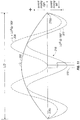
- FIG. 7 is a further illustration of the instantaneous current density patterns from FIG. 6B with the half-wave di-pole antenna 216 of FIG. 3 driven by the microwave energy generation circuit 150 of FIG. 5 .
- the half-wave di-pole antenna 216 may have a physical length of approximately ⁇ /2 or another suitable length that produces resonance.
- FIG. 7 includes a graphical representation of the instantaneous maximum current density along the antenna 216 for the microwave signal from FIG. 6A with a wavelengths of ⁇ 300, the microwave signal with a wavelength of ⁇ 3th 310 and a resultant current density waveform 330d formed by combining the microwave signals with wavelengths of ⁇ 300 and ⁇ 3th 310.
- the ⁇ current density 300d is illustrative of the current density generated in the surrounding medium by an antenna when driven by the microwave waveform provided to Port A of the signal mixer 158 of FIG. 5 .
- the ⁇ 3th current density 310d is illustrative of the current density generated in the surrounding medium by an antenna when driven by the microwave waveform provided to Port B of the signal mixer 158 of FIG. 5 .
- the resultant current density waveform, provided on Port C of the signal mixer 158 of FIG. 5 is the sum of the ⁇ 300d and ⁇ 3th 310d waveforms, is generated by the signal mixer 158 and provided to Port C.
- the maximum instantaneous current densities 300d, 310d and 330d, generated by driving the microwave antenna with the various waveforms are generally scaled to approximate the relative intensity level between the microwave waveforms.
- the waveforms at Ports A and B are in phase and have a 1:1 intensity level.
- the magnitude of the resultant current density of the waveform at Port C is shown as 330d and is equal to: Abs ⁇ + ⁇ 3 ⁇ rd
- the waveforms in FIG. 7 illustrate the current density of each waveform at the instantaneous point in time when the waveforms ⁇ 300 and waveform ⁇ 3th 310 are a maximum and is a further illustration of the plot PHASE 90 from FIG. 7B .
- the resultant current density waveform 300d is a maximum at a point proximal to the midpoint of the proximal radiating portion 216a and a point distal to the midpoint of the distal radiating portion 216b.
- the current density is a minimum at the distal and proximal ends of the antenna 216 and at the midpoint of the antenna 216.
- the instantaneous resultant current density waveform 330d in FIG. 7 may be a maximum, as illustrated in FIGS. 6A-6B and discussed hereinabove, the maximum resultant current density is only generated at a single instantaneous point in time and the resultant current density waveform exhibits many additional shapes over time thereby resulting in an ablation region that may resemble the maximum resultant current density waveform 330d but also exhibits may other features.
- the current densities and instantaneous current densities illustrated herewithin are provided to demonstrate the synergistic affect of combining two or more microwave frequencies.
- the current density generated from the resultant current density waveforms may reflect a general shape of a potential ablation region when the energy delivered to tissue is at a maximum.
- an ablation region formed from an antenna producing one of the current densities illustrated herewithin is dependant on several other factors including, but not limited to, the varying current density of the resultant current density waveform, the properties of the surrounding medium, the rate of energy delivery to the medium and the total energy delivered to the medium.
- the figures contained herein provide a comparison between the current density generated by a signal with energy at a single microwave frequency and the current density of a resultant current density waveform generated from combining two or more microwave frequencies.
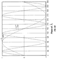
- FIG. 8A is a plot of two waveforms, ⁇ 400 and ⁇ 3rd 410, wherein ⁇ 3rd 410 is the third harmonic of ⁇ 400 and ⁇ 400 and ⁇ 3rd 410 are out of phase by with respect to each other.
- Waveform ⁇ 400 leads waveform ⁇ 3rd 410 by 30° with respect to the ⁇ 400 time scale (or a 90° lag with respect to a ⁇ 3rd 410 time scale).
- time is represented in the time scale or 'phase angle' of the ⁇ 400 waveform and the magnitude of the waveforms are normalized.
- FIG. 8B illustrates the two waveforms ⁇ 400 and ⁇ 3th 410 from FIG. 8A and the current density pattern of the resultant current density waveform 430a-1 at a plurality of instantaneous points in time.
- the time interval is shifted by 30° thereby illustrating the change in the instantaneous current density patterns of the two waveforms 400a-1, 410a-1 and the resultant current density pattern waveform 430a-1.
- Plots are normalized to the resonant frequency such that the 'ends' of the antenna are at 0 and 3.
- the current at the antenna 'ends' are idealized at 0 magnitudes. While the present embodiment illustrates a balanced dipole antenna the embodiments illustrated herewithin may be used with other types of antennas, such as, for example, an unbalanced dipole antenna and.
- waveforms ⁇ 400a exhibits 'null' current along the antenna and waveform ⁇ 3rd 410a is a maximum.
- the resultant current density waveform 430a is equal to the current density pattern generated by the waveform ⁇ 3rd 410a.
- waveform ⁇ 3rd 410b exhibits 'null' current along the antenna and waveform ⁇ 400b is growing to about half of the absolute peak.
- the resultant current density waveform 430b is distributed sinusoidally along the dipole.
- waveform ⁇ 3th 410c is a maximum and waveform ⁇ 400c is approaching a maximum in the opposite direction.
- the current density generated for waveform ⁇ 400c and waveform ⁇ 3th 310c are additive at the ends of the antenna and cancel near the feedpoint. As such, the resulting current density pattern 430c is greater at the ends of the antenna with little current at the feedpoint.
- waveform ⁇ 3th 410d exhibits 'null' current along the antenna and the resultant current density waveform 430d is equal to waveform ⁇ 400d, which is a maximum and distributed sinusoidally along the dipole,
- waveform ⁇ 3th 410e is a maximum and waveform ⁇ 400e is slightly less than a maximum.
- the resultant current density waveform 430e is a maximum at the feedpoint and greater than waveforms ⁇ 400e and ⁇ 3th 410e individually.
- waveform ⁇ 3th 410f exhibits 'null' current along the antenna and the resultant current density waveform 430f is equal to waveform ⁇ 400f, which is decaying to less than half of the peak, approaching zero and distributed sinusoidally along the dipole.
- ⁇ 400g exhibits 'null' current along the antenna and the resultant current density waveform 400g is equal to waveform ⁇ 3th 410g, which is at a maximum thereby forming current density peaks at the feedpoint and the distal and proximal ends of the antenna.
- waveform ⁇ 3th 410h exhibits 'null' current along the antenna and the resultant current density waveform 430h is equal to waveform ⁇ 400h, which growing to a maximum in the opposite direction and distributed sinusoidally along the dipole.
- waveform ⁇ 3th 410i is a maximum and waveform ⁇ 400i is approaching a maximum in the opposite direction.
- the current density generated for waveform ⁇ 400i and waveform ⁇ 3th 410i are additive at the ends of the antenna and are opposite at the feedpoint.
- the resulting current density pattern 430i is greater at the ends of the antenna with little current at the feedpoint.
- waveform ⁇ 3th 410j exhibits 'null' current along the antenna and the resultant current density waveform 430j is equal to waveform ⁇ 400j, which is a maximum and distributed sinusoidally along the dipole.
- waveform ⁇ 3th 410k is a maximum and waveform ⁇ 400k is slightly less than a maximum.
- the resultant current density waveform 430k is a maximum at the feedpoint and greater than waveforms ⁇ 400k and ⁇ 3th 410k individually.
- waveform ⁇ 3th 4101 exhibits 'null' current along the antenna and the resultant current density waveform 4301 is equal to waveform ⁇ 4001.
- the cycle is a repeating cycle with the current density patterns in the PHASE 0 plot synonymous with a 360° phase angle plot that would follow the PHASE 330 plot illustrated in FIG. 8B .
- resultant current density waveform 430a-1 generates three relative maximum current density regions at a phase angles of 0° (PHASE 0), one maximum current density region at a phase angle of 30° (PHASE 30) and two relative maximum current density regions at a phase angle of 60° (PHASE 60).
- the resultant current density waveforms 430a-1 generate one relative maximum current density region in the plots at phase angles of 30°, 90°, 150°, 210°, 270° and 330° PHASE 30, PHASE 90, PHASE 150, PHASE 210, PHASE 300°, respectively.
- the resultant current density waveforms 330a-1, 430a-1 are dependant on the properties of the two waveforms 300 and 310, 400 and 410, respectively, (i.e., frequency, magnitude, energy content) and the phase relationship between the two waveforms 300 and 310, 400 and 410, respectively.
- a comparison between the resultant current density waveforms 330a-1 in FIG. 6B and the resultant current density waveforms 440a-1 in FIG. 8B illustrates the effect of phase shifting the waveforms 300, 310, 400, 410 relative to each other.
- waveform ⁇ 300 are an absolute maximum at 90° and 270°.
- the relative maximums for waveform ⁇ 3th 300 are in phase with the relative maximums of waveform ⁇ 330 thereby resulting in a unique set of instantaneous current densities illustrated in FIG. 6B .
- the relative maximums for waveform ⁇ 3th 400 are not phase with the relative maximums of waveform ⁇ 430 thereby resulting in the unique set of instantaneous current densities as illustrated in FIG. 8B .
- the two waveforms 300, 310 and 400, 410 that are combined to generate the resultant current density waveforms are identical in frequency in magnitude but phase-shifted relative to each other.
- This phase shift results in a resultant current density waveform 330a-1, 430a-1 with new and unique features and may result in an ablation region related to the new and unique features of the resultant current density waveforms 330a-1, 430a-1 (i.e., the ablation region generated in the surrounding medium by the antenna driven with the resultant current density waveform 330a-1, 430a-1 will form a shape related to this transient current density, therefore the shape of the ablation region may exhibit features from each current density regions).
- the ablation region produced in the surrounding medium by the antenna will be irregularly shaped.
- the ablation region may exhibit features that resemble features from one or more of the plots illustrated in FIG. 6B .
- the ablation region may include one or more features adjacent the ends of the antenna generated by the relative current density regions illustrated in the plots PHASE 0, PHASE 60, PHASE 120, PHASE 180, PHASE 240 and PHASE 300.
- the ablation region may include one or more features between the proximal and distal ends of the antenna and one or more features between the relative current density regions adjacent the feedpoint as illustrated in the plots PHASE 0, PHASE 120, PHASE 180 and PHASE 300.
- an approximation of the ablation region formed by the resultant current density waveform 400a-1 may be estimated by the energy contribution during each phase of the resultant current density waveform.
- the magnitude of the current density of the resultant current density waveform is a maximum at phase angles of 120° and 300° (see PHASE 120, PHASE 300), therefore, the energy contributed to the surrounding medium may be at a maximum during this instantaneous point in time. This may result in the general overall shape of the ablation region to be more related to the current density patterns at these phase angles.
- the ablation region may include additional features generated during the various other phase angles, as discussed hereinabove.
- the phase-shift between the microwave signals may produce a resultant current density waveform that provides deep penetration of energy into tissue.
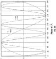
- FIG. 9A is a plot of two waveforms, ⁇ 500 and ⁇ 3th 510, wherein ⁇ 3th 510 is the third harmonic of ⁇ 500 and ⁇ 500 and ⁇ 3th 510 are out of phase by with respect to each other.
- Waveform ⁇ 500 leads waveform ⁇ 3th 510 by 60° with respect to the ⁇ 500 time scale (or a 180° lag with respect to the ⁇ 3th 510 time scale).
- time is represented in the time scale or 'phase angle' of the ⁇ waveform 500 and the magnitude of the waveforms 500, 510 are normalized.
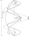
- FIG. 9B illustrates the two waveforms ⁇ 500 and ⁇ ⁇ 3th 510 from FIG. 9A and the current density pattern of the resultant current density waveform 530a-5301 at a plurality of instantaneous points in time.
- the time interval is shifted by 30° thereby illustrating the change in the instantaneous current density patterns of the two waveforms 500a-5001, 510a-5001 and the resultant current density pattern waveform 530a-5001.
- Plots are normalized to the resonant frequency such that the 'ends' of the antenna are at 0 and 3.
- the current at the antenna 'ends' are idealized at 0 magnitudes. While the present embodiment illustrates a balanced dipole antenna the embodiments illustrated herewithin may be used with other types of antennas, such as, for example, an unbalanced dipole antenna.
- waveforms ⁇ 500a exhibits 'null' current along the antenna and waveform ⁇ 3th 510a is a maximum.
- the resultant current density waveform 530a is equal to the current density pattern generated by the waveform ⁇ 3th 510a.
- waveform ⁇ 3th 510b is a maximum and waveform ⁇ 500b is growing to about half of the absolute peak in the opposite direction.
- the resultant current density waveform 530b includes a maximum current density adjacent the antenna feed point and a relative maximum current densities adjacent the ends of the antenna.
- waveform ⁇ 3th 510c exhibits 'null' current along the antenna and the resultant current density waveform 530c is equal to waveform ⁇ 500c, which is approaching a maximum.
- waveform ⁇ 500d and ⁇ 3th 510d are a maximum and the resultant current density waveform 530d generates a maximum current density at the feed point equal to about twice the current density of waveforms ⁇ 500d and ⁇ 3th 510d individually.
- waveform ⁇ 3th 510e exhibits 'null' current along the antenna and the resultant current density waveform 530e is equal to waveform ⁇ 500e, which is decreasing from a maximum.
- waveform ⁇ 3th 510f is a maximum and waveform ⁇ 500f is decreasing and about half of the absolute peak in the opposite direction.
- the resultant current density waveform 530f includes a maximum current density adjacent each end of the antenna and a relative maximum current density at the antenna feedpoint.
- waveforms ⁇ 500g exhibits 'null' current along the antenna and waveform ⁇ 3th 510g is a maximum.
- the resultant current density waveform 530g is equal to the current density pattern generated by the waveform ⁇ 3th 510g.
- waveform ⁇ 3th 510h is a maximum and waveform ⁇ 500h is decreasing and about half of the absolute peak in the opposite direction.
- the resultant current density waveform 530h includes a maximum current density adjacent each end of the antenna and a relative maximum current density at the antenna feedpoint.
- waveform ⁇ 3th 510i exhibits 'null' current along the antenna and the resultant current density waveform 530i is equal to waveform ⁇ 500i, which is decreasing to a maximum.
- waveforms ⁇ 500j and ⁇ 3th 510j are a maximum and the resultant current density waveform 530d generates a maximum current density at the feed point equal to about twice the current density of waveforms ⁇ 500 and ⁇ 3th 510d individually.
- the current flow is equal in magnitude and opposite in of the current generated by the resultant current density waveform 530d in plot PHASE 90.
- waveform ⁇ 3th 510k exhibits 'null' current along the antenna and the resultant current density waveform 530k is equal to waveform ⁇ 500k, which is decreasing from a maximum.
- waveform ⁇ 3th 5101 is a maximum and waveform ⁇ 5001 is decreasing and about half of the absolute peak in the opposite direction.
- the resultant current density waveform 5301 includes a maximum current density adjacent each end of the antenna and a relative maximum current density at the antenna feedpoint.
- the cycle is a repeating cycle with the current density patterns in the PHASE 0 plot synonymous with a 360° phase angle plot that would follow the PHASE 330 plot illustrated in FIG. 9B .
- FIG. 8A and FIG. 9A shifting the phase of one waveform relative to the other waveform may result in deep penetration of energy into tissue.
- the plots in FIGS. 6A and 8A illustrate current density patterns that provide energy penetration at both the feedpoint and the ends of the antenna while the plots in FIG. 9A provide the greatest energy penetration at the feedpoint.
- both waveforms ⁇ 500 and ⁇ 3th 510 are at a maximum magnitude in the same direction at 90° and 270°.
- the current density waveforms plots in FIG. 9B at 90° and 270° PHASE 90, PHASE 270 further illustrate that the resultant current density waveforms 530d, 530j provide maximum energy penetration into tissue.
- the microwave energy generation circuit 150 of FIG. 5 may combine a first and second microwave signal with various frequency and/or phase combinations to generate a desirable resultant current density waveform as discussed hereinabove.
- FIGS. 10-16 provide further illustrations of specific frequency and phase combinations. Each of FIGS. 10-16 include plots of the instantaneous current density patterns in which the first and second microwave signals that are combined to generate a resulting waveform are at a maximum.
- the resultant current density waveform is also an instantaneous current density waveform and is only an exemplary example of the varying current density waveforms as illustrated in FIGS. 6A and 6B , FIGS. 8A and 8B , and FIGS. 9A and 9B .
- FIG. 10 illustrates current density plots of a microwave signal with a wavelength of ⁇ 300, supplied to Port A, a microwave signal with a wavelength of ⁇ 5th 332, supplied to Port B and the resultant current density waveform 332.
- the waveforms at Ports A and B are in phase and have a 1:1 intensity level.
- the magnitude of the resultant current density is shown as 336 and is equal to: Abs ⁇ + ⁇ 5 ⁇ th
- the current density is a maximum near the midpoint of the proximal radiating portion 216a and near the midpoint of the distal radiating portion 216b.
- a second relative current density maximum is located proximal the distal end of the antenna 216 and distal the proximal end of the antenna 216.
- the current density is a minimum at the midpoint of the antenna 216, the endpoints of the antenna 216 and approximately midway between each of the maximum current density and the relative maximum current density on both the distal and proximal radiating portions 216a, 216b,
- the higher frequency waveform ⁇ 5th 320 when combined with waveform ⁇ 300, provides a relative maximum current density portion adjacent the proximal end of the proximal antenna portion 216a and the distal end of the distal antenna portion 216b.
- the higher frequency waveform ⁇ 5th positions the relative maximum current density portions further to the ends of the antenna.
- FIG. 11 illustrates current density plots of a microwave signal with a wavelength of ⁇ 300, supplied to Port A, a microwave signal with a wavelength of ⁇ 5th 322, supplied to Port B and the resultant current density waveform 336.
- the ⁇ 300 waveform leads the ⁇ 5th 322 waveform by 36° on the ⁇ phase angle (180° on the ⁇ 5th phase angle).
- Ports A and B are shifted in phase by 36 degrees and have a 1:1 intensity level.
- the magnitude of the resultant current density is shown as 336 and is equal to: Abs ⁇ + ⁇ 5 ⁇ th @ 180 °
- the resultant current density waveform 336 exhibits "null" current at the midpoint with a maximum current density portion and a relative maximum current density portion toward the proximal and distal ends 216a, 216b of the antenna 216.
- FIG. 12 illustrates current density plots of a microwave signal with a wavelength of ⁇ 3rd 310, supplied to Port A, a microwave signal with a wavelength of ⁇ 5th 320 supplied to Port B and the resultant current density waveform 340.
- the waveforms at Ports A and B are in phase and have a 1:1 intensity level.
- the current density for a ⁇ 300 waveform is provided for reference.
- the magnitude of the resultant current density 340 of the waveform at Port C is equal to: Abs ⁇ 3 ⁇ rd + ⁇ 5 ⁇ th
- the resultant current density waveform 340 exhibits "null" current at the midpoint with a maximum current density portion adjacent the proximal and distal ends 216a, 216b of the antenna 216.
- Two relative current density maximums are positioned between the feedpoint and the maximum current density portion.
- the current density is a minimum at the distal and proximal ends of the antenna 216, the midpoint of the antenna 216 and near the midpoint of the distal and proximal radiating portions 216a, 216b. In general, the current density is focused toward the distal and proximal ends of the antenna 216.
- FIG. 13 illustrates current density plots of a microwave signal with a wavelength of ⁇ 3rd 312, supplied to Port A, a microwave signal with a wavelength of ⁇ 5th 320 supplied to Port B and the resultant current density waveform 342.
- the waveforms at Ports A and B are in phase and have a 3:1 intensity level.
- a microwave waveform with a wavelength of ⁇ 300 is provided for reference.
- the magnitude of the resultant current density of the waveform at Port C is shown as 342 and is equal to: Abs ⁇ 3 ⁇ rd * 3 + ⁇ 5 ⁇ th )
- the resultant current density waveform is at a maximum near the proximal and distal ends 216a, 216b of the antenna 216.
- a relative maximum current density is also centered about the midpoint of the antenna 216.
- the current density is a minimum at the proximal and distal ends 216a, 216b of the antenna 216 and midway between the feedpoint and the maximum current density portions.
- current density 342 is focused near the distal end of the antenna 216, near the proximal end of the antenna 216 and about the antenna 216 midpoint.
- the resultant current density waveform 342 illustrated in FIG. 13 provide an example of a waveform that advantageously creates an ablation region through both microwave heating and conductive heating.
- the microwave heating creates a current density pattern 340 with focused energy delivery towards the proximal and distal ends 216a, 216b.
- the tissue portion at the feedpoint, midway between the maximum current density regions, receives energy from microwave heating and from energy conducted from the maximum current density regions proximal and distal the feedpoint.
- FIG. 14 illustrates current density plots of a microwave signal with a wavelength of ⁇ 3rd 310, supplied to Port A, a microwave waveform with a wavelength of ⁇ 5th 322 supplied to Port B and the resultant current density waveform 344.
- the waveforms at Ports A and B are phase-shifted by 180° on the ⁇ 5th scale and have a 1:1 intensity level.
- a microwave waveform with a wavelength of ⁇ 300 is provided for reference.
- the magnitude of the resultant current density of the waveform at Port C is shown as 344 and is equal to: Abs ⁇ 3 ⁇ rd + ⁇ 5 ⁇ th @ 180 °
- the current density is at a maximum at the midpoint of the antenna 216 with the current density for the ⁇ 3th 310 and ⁇ 5th waveforms 322 are a maximum.
- First pair of relative current density maximums are positioned about the midpoint of the proximal and distal radiating portions 216a, 216b with a second pair of smaller relative current density maximums near the proximal and distal ends of the antenna 216.
- the current density is a minimum between the maximum current density and the first pair of relative current density maximums and between the first and second pair of relative current density maximums.
- the resultant current density waveform 344 extends well beyond the maximum current density of the ⁇ waveform 300. As such, the waveforms of ⁇ 3rd 310 + ⁇ 5th @ 180° 344 and the ⁇ waveform 300 may produce ablation regions of similar in size and shape.
- FIG. 15 illustrates current density plots of a microwave signal with a wavelength of ⁇ 3rd 314, supplied to Port A, a microwave signal with a wavelength of ⁇ 5th 322 supplied to Port B and the resultant current density waveform 346.
- the waveforms at Ports A and B are phase-shifted by 180° on the ⁇ 5th scale and have a 1:1 intensity level.
- a microwave waveform with a wavelength of ⁇ 300 is provided for reference.
- the magnitude of the resultant current density of the waveform at Port C is shown as 346 and is equal to: Abs ⁇ 3 ⁇ rd * 3 + ⁇ 5 ⁇ th @ 180 °
- the current density is at a maximum at the midpoint of the antenna with a pair of relative current density maximums positioned near the midpoint of the proximal and distal radiating portions 216a, 216b.
- the current density is a minimum between the maximum current density and each of the relative current density maximums.
- the magnitude of current density 346 extends to, and beyond, the current density of the microwave waveform with a wavelength of ⁇ 300.
- the waveforms of ⁇ 3rd *3 + ⁇ 5th @ 180° may produce ablation regions of similar in shape and size, if not larger size, than the waveform of ⁇ 300.
- tissue and/or energy properties may also be employed for determining or selecting the properties of the microwave signals, such as, for example, tissue temperature, power delivered to the surrounding medium and power reflected from the surrounding medium.
- the microwave generator may dynamically adjust one or more properties of energy delivery based on a measured value.
- the processor 151 in FIG. 5 may store a plurality of previously entered energy delivery parameter combinations, and the resulting current density patterns, and one or more of the energy delivery parameter combinations may be selected to produce an ablation region
Description
- The present invention relates generally to medical / surgical ablation systems for delivering microwave energy to tissue. More particularly, the present disclosure relates to the spectral frequency content of the energy delivered to tissue to achieve deep penetration of energy.
- In the treatment of diseases such as cancer, certain types of cancer cells have been found to denature at elevated temperatures (which are slightly lower than temperatures normally injurious to healthy cells). These types of treatments, known generally as hyperthermia therapy, typically utilize electromagnetic radiation to heat diseased cells to temperatures above 41° C while maintaining adjacent healthy cells at lower temperatures to insure that irreversible cell destruction does not occur. Other procedures utilizing electromagnetic radiation to heat tissue also include ablation and coagulation of the tissue. Such microwave ablation procedures, e.g., such as those performed for menorrhagia, are typically performed to ablate and coagulate the targeted tissue to denature or kill the tissue. Many procedures and types of devices utilizing electromagnetic radiation therapy are known in the art. Such microwave therapy is typically used in the treatment of tissue and organs, such as the prostate, heart, and liver.
- One less invasive procedure generally involves the treatment of tissue (e.g., a tumor) underlying the skin via the use of microwave energy. While microwave energy is able to penetrate the skin to reach the underlying tissue, the depth of penetration is typically dependant on several factors such as the physical properties of the tissue, the type of ablation instrument used for ablation, the current density pattern generated by the ablation instrument and the rate of energy delivery to tissue, and the spectral content of the energy.
- The first factor, the physical properties of the tissue, is determined by the target tissue to be ablated, (i.e., the cancerous tissue) and the healthy tissue surrounding the target tissue. Obviously, a clinician cannot control the size or shape of the target tissue, or the location of the target tissue in the patient's body, but a clinician can select the type and number of ablation instruments, adjust the amount of delivered power, adjust the rate of energy delivery and vary the spectral content of the microwave energy.
- In a conventional system, the spectral content of the energy is fixed to a particular frequency, such as, for example, 915 MHz, 2450 MHz and 10 GHz. The spectral content of the microwave signal determines the current density along the antenna and the amount of microwave energy delivered to the surrounding medium typically determines the depth of energy penetration and the shape of the resulting ablation region. For example, it is well known that a device delivering energy at 10 GHz only penetrates tissue a few millimeters while a device delivering energy at 915 MHz may penetrate tissue several centimeters.
- Delivery of microwave energy at a single microwave frequency provides specific advantages and disadvantages. The present disclosure overcomes disadvantages of delivering energy at a specific frequency by disclosing an electrosurgical system, device and methods to simultaneously delivery microwave energy at a plurality of microwave frequencies which may allow better control over energy delivery and deposition around the instrument, as well as potentially sensing or determining the ablation shape or completeness by using antenna matching at different spectral combinations.
US2005205566 A1 ,US4448198 A1 disclose systems similar to the present invention. - The present invention is defined by
independent claim 1. Preferred embodiments are disclosed in the dependent claims. A system for delivering energy is disclosed. The system includes a housing having an antenna attached to the distal end configured to receive a microwave signal and radiate energy at two or more wavelengths and a microwave generator operably connecting to the antenna that provides the microwave signal to the antenna. The microwave generator generates a combined microwave signal containing microwave energy having at least a first and a second wavelength. The at least a first and second wavelengths are both capable of creating resonance in the antenna. - The system includes a first microwave signal generator that generates a first microwave signal at the first wavelength, a second microwave signal generator that generates a second microwave signal at the second wavelength and a signal mixer that combines the first and second microwave signals to generate the combined microwave signal. The first wavelength is related to a first frequency and the second wavelength is related to a harmonic of the first frequency. The harmonic may be a third or a fifth harmonic. The first frequency may be about 915 MHz. The system includes a phase shifter configured to shift the phase of one of the first and second microwave signals relative to each other. The phase shifter may shift the phase between the first and second microwave signals between about 0° and 360°.
- In one embodiment, the system also includes an amplifier that amplifies at least one of the first and second microwave signals to a desired intermixing ratio. The mixing ratio may be between about 1:99 and 99: An amplifier is provided to amplify the combined microwave signal. In yet another embodiment, the system may further include a processor configured to control a parameter of the first microwave signal, the second microwave signal or the combined signal.
- Various embodiments of the present disclosure are described herein with reference to the drawings wherein:
-
FIG. 1 is a perspective view of an electrosurgical system according to an embodiment of the present disclosure; -
FIG. 2 is a transverse cross-sectional view of the distal end of the microwave energy delivery device ofFIG. 1 ; -
FIG. 3 is a graphical illustration of the half-wave di-pole antenna portion ofFIG. 2 , with an illustration of the corresponding current density created along the antenna when driven by microwave signals with wavelengths of λ; -
FIG. 4 is a graphical illustration of the half-wave di-pole antenna portion ofFIG. 3 , with an illustration of the corresponding current density created along the antenna when driven by microwave signals with wavelengths of λ, λ3rd, and λ5th; -
FIG. 5 is a block diagram of the microwave energy generation circuit fromFIG. 1 for generating and combining microwave signals with two or more wavelengths, according to the present invention; -
FIG. 6A is a graphical illustration of the waveforms λ and λ3th, with time represented as the 'phase angle' of the λ waveform with the magnitude of the two waveforms normalized; -
FIG. 6B is a time series of graphical illustrations of current density patterns at instantaneous points in time generated by an antenna driven by waveforms λ and λ3th fromFIG. 6A and the resultant current density waveform; -
FIG. 7 is a graphical illustration of the half-wave di-pole antenna portion ofFIG. 2 , with an illustration of the corresponding current density created along the antenna when driven by microwave signals with wavelengths of λ, λ3rd and the resultant current density waveform; -
FIG. 8A is a graphical illustration of the waveforms λ and λ3th, with time represented as the 'phase angle' of the λ waveform, the two waveforms phase shifted by 30° relative to the λ waveform with the magnitude of the two waveforms normalized; -
FIG. 8B is a time series of graphical illustrations of current density patterns at instantaneous points in time generated by an antenna driven by waveforms λ and λ3th fromFIG. 8A and the resultant current density waveform; -
FIG. 9A is a graphical illustration of the waveforms λ and λ3th, with time represented as the 'phase angle' of the λ waveform, the two waveforms phase shifted by 60° relative to the λ waveform with the magnitude of the two waveforms normalized; -
FIG. 9B is a time series of graphical illustrations of current density patterns at instantaneous points in time generated by an antenna driven by waveforms λ and λ3th fromFIG. 9A and the resultant current density waveform; -
FIG. 10 is a graphical illustration of the half-wave di-pole antenna portion ofFIG. 2 , with an illustration of the corresponding current density created along the antenna when driven by microwave signals with wavelengths of λ, λ5th and the resultant current density waveform; -
FIG. 11 is a graphical illustration of the half-wave di-pole antenna portion ofFIG. 2 , with an illustration of the corresponding current density created along the antenna when driven by microwave signals with wavelengths of λ, λ3rd phase shifted by 180° and the resultant current density waveform; -
FIG. 12 is a graphical illustration of the half-wave di-pole antenna portion ofFIG. 2 , with an illustration of the corresponding current density created along the antenna when driven by microwave signals with wavelengths of λ3rd, λ5th phase shifted by 180° and the resultant current density waveform; -
FIG. 13 is a graphical illustration of the half-wave di-pole antenna portion ofFIG. 2 , with an illustration of the corresponding current density created along the antenna when driven by microwave signals with wavelengths of λ3rd, λ5th and the resultant current density waveform wherein the waveform λ3rd and λ5th are a 3:1. intensity level; -
FIG. 14 is a graphical illustration of the half-wave di-pole antenna portion ofFIG. 2 , with an illustration of the corresponding current density created along the antenna when driven by microwave signals with wavelengths of λ3rd, λ5th phase shifted by 180° and the resultant current density waveform; and -
FIG. 15 is a graphical illustration of the half-wave di-pole antenna portion ofFIG. 2 , with an illustration of the corresponding current density created along the antenna when driven by microwave signals with wavelengths of λ3rd, λ5th phase shifted by 180° and resultant current density waveform wherein the waveform λ3rd and λ5th are a 3:1 intensity level. - Embodiments of the presently disclosed microwave antenna assembly are described in detail with reference to the drawing figures wherein like reference numerals identify similar or identical elements. As used herein and as is traditional, the term "distal" refers to the portion which is furthest from the user and the term "proximal" refers to the portion that is closest to the user. In addition, terms such as "above", "below", "forward", "rearward", etc. refer to the orientation of the figures or the direction of components and are simply used for convenience of description.
- During treatment of diseased areas of tissue in a patient, the insertion and placement of an microwave energy delivery apparatus, such as a microwave antenna assembly, relative to the diseased area of tissue is preferable for successful treatment. Generally, the microwave antenna assemblies described herein allow for direct insertion into tissue and include a half-wave dipole antenna at the distal end. An microwave assembly for percutaneous insertion into tissue is described in
U.S. Patent No. 6,878,147 to Prakash, issued on April 12, 2005 . - One critical aspect of placement of a microwave energy delivery apparatus is determining the size and shape of the ablation area produced by the device and insuring that the target tissue is contained within this ablation area.
- Referring now to
FIG. 1 , a combined frequency microwave ablation system (hereinafter "microwave ablation system"), according to an embodiment of the present disclosure, is shown assystem 10.Microwave ablation system 10 includes a combined frequency microwave generator 100 (hereinafter "microwave generator") connected to a microwaveenergy delivery device 110 via atransmission line 120 and, in some embodiments, a coolingfluid supply 130.Microwave generator 100 includes ahousing 130 that houses a microwaveenergy generation circuit 150 and adelivery device port 160 that connects to thedevice connector 170 of thetransmission line 120. - Microwave
energy delivery device 110 includes ahandle 112 and anelongate shaft 114 including anantenna 116 on the distal end. Distal portion ofantenna 116 may form a sharpenedtip 118 for percutaneous insertion intopatient tissue 180. If present, a coolingfluid supply 130 supplies cooling fluid to microwaveenergy delivery device 110 via supply and returntubes handle 112. - Microwave
energy delivery device 110 may be designed and intended for use with a conventional system that supplies microwave energy at a single microwave frequency or microwave energy delivery device may be specifically designed and intended for use with a combinedfrequency microwave generator 100. While the present disclosure describes a combined frequencymicrowave ablation system 10 and methods of use with a percutaneous type microwave energy delivery device, the systems and methods disclosed herewithin may be used with any suitable microwaveenergy delivery device 110 capable of delivering microwave energy, such as, for example, a catheter-type device, an endoscopic device and a surface delivery device (not shown). -
FIG. 2 is a transverse cross-sectional view of the distal end of a microwaveenergy delivery device 110 similar to the device ofFIG. 1 .Antenna 216 is a conventional half-wave dipole microwave antenna.Antenna 216 includes aproximal radiating portion 216a connected to afeedline 220 at the proximal end thereof, and adistal radiating portion 216b. Sharpenedtip 218 may be part of thedistal radiating portion 216b or sharpenedtip 218 may connect todistal radiating portion 216b and configured to not radiate energy.Antenna 216 comprisesproximal radiating portion 216a anddistal radiating portion 216b.Proximal radiating portion 216a may typically have anouter conductor 222 and aninner conductor 224, each of which extends along a longitudinal axis. Between the outer andinner conductors dielectric material 226 that is disposed longitudinally between theconductors Dielectric material 226 may constitute any number of appropriate materials, including air. Proximal anddistal radiating portions junction 216c, typically formed of a dielectric material.Junction 216c may be supported byinner conductor 224 that runs throughjunction 216c and at least partially extends intodistal radiating portion 216b. - In use, a conventional system generates a microwave energy signal having a wavelength of λ and transmits the signal through a
transmission line 220 toantenna 216.Antenna 216 transmits energy from the proximal anddistal radiating portions - In general, an E-field, generated by the time-varying magnetic field, exerts a force on other electrically charged objects. While "E-fields" and "magnetic fields" are not the same, they cannot be completely separable. Therefore, for the sake of clarity the term "electromagnetic field" will be used to describe an E-field, a magnetic field or the combined forces generated by either an E-field or magnetic field. The electromagnetic field may produce localized movement of H20 molecules, i.e., vibrational and/or rotational movement, or the electromagnetic field may induce current flow over very short distances. This agitation, friction and/or induced current between molecules produces heat in the surrounding medium. The strength of the E-field at a given point is defined as the force that would be exerted on a charge at any given that point and the direction of the E-field is given by the direction of that force.
- The strength of the electromagnetic field may be represented by the current density (i.e., the measure of the density of a conserved charge) in the surrounding tissue. While current density is typically related to electric current, in the present disclosure current density generally represents the magnitude and relative strength of the electromagnetic field generated when a microwave signal is applied to the antenna.
- The physical length of the
antenna 216 for efficient radiation of microwave energy may depend on several factors. One factor is the effective wavelength, λeff, which is dependent upon the dielectric properties of the surrounding medium.Antenna 216 through which microwave energy is transmitted at a wavelength, λ, may have differing effective wavelengths, λeff, depending upon the surrounding medium, e.g., liver tissue, as opposed to, e.g., breast tissue. Also affecting the effective wavelength, λeff, are coatings which may be disposed overantenna 216. - For simplicity, in the present disclosure a wavelength of the signal generated by the microwave generator and supplied to the
antenna 216 is generically referenced as λ, wherein the physical length of theantenna 216 is approximately about one-half the wavelength of the microwave signal, or λ/2, and is the "effective' λ of the antenna in the respective media. -
FIG. 3 is the half-wave di-pole antenna 216 ofFIG. 2 , with a graphical illustration of the corresponding instantaneouscurrent density 300 along theantenna 216 when supplied with a microwave signal at a wavelength of λ.Antenna 216 includes proximal anddistal radiating portions antenna 216. The maximum current is at the center of the di-pole with zero current density at each end. Thecurrent density 300 is a representation of the instantaneous relative energy penetration in the surrounding medium related to the electromagnetic field patterns / waves radiated into surrounding tissue. - While the
antenna 216 illustrated inFIG. 3 is a balanced di-pole antenna wherein the proximal anddistal radiating portions distal radiating portions -
Antenna 216 may also resonate and deliver energy to the surrounding medium when driven with signals containing additional wavelengths, wherein the wavelengths are odd multiple harmonics of λ. As illustrated inFIG. 4 , a half-wave di-pole antenna with a physical length approximately equal to λ/2 will also resonate with wavelengths of λ,λ 3rd 310 andλ 5th 320, whereinλ 3rd 310 andλ 5th 320 are third and fifth harmonics of λ, respectively. The physical length of the antenna is equal to λ/2 for a wavelength ofλ 300, 3λ3rd/2 for a wavelength ofλ 3rd 310 and 5λ5th/2 for a wavelength ofλ 5th 320. The current densities forλ 300,λ 3rd 310 andλ 5th 320 are sinusoidal in shape withλ 300 having a single sinusoidal node, λ3rd having three sinusoidal nodes andλ 5th 320 having five sinusoidal nodes. - When supplying energy to
antenna 216 at a single wavelength, such as, for example, λ, λ3rd or, λ5th, heating of the surrounding medium is dependant on the current density and the current density is similar in shape to the absolute value of thewaveform - As illustrated in
FIG. 3 , providing a microwave signal, with a wavelength of λ and a frequency of 915 MHz, to anantenna 216 with a physical length of approximately λ/2 will generate current 300 in a sinusoidal distribution. The current 300 relates to the electromagnetic field and results in heating of the surrounding medium. The size of the resulting ablation area is related to the magnitude of the current 300 thus forming a circular ablation region. Ablation region may also be described as a donut or torus shaped region. - As illustrated in
FIG. 4 , anantenna 216 with a length of λ/2 will also resonate and delivery energy into the surrounding medium when supplied with the thirdharmonic λ 3rd 310 of λ and the fifth harmonics λ5th 320 of λ. For example, an antenna that resonates at about 915 MHz, orλ 300, will also resonate at about 2.525 GHz, or λ3rd, and at 4.209 GHz, or λ5th. For illustrative purposes, the sine waves and other waveforms described herein relate to current density in a direction at a specific moment in time, wherein a portion of the waveform above the dipole provides the magnitude of the current moving to the right and a portion of the waveform below the dipole provides the magnitude of the current moving to the left. - At wavelengths of λ3rd and λ5th the magnitude of current 310, 320, respectively, along the
antenna 216 is different than the magnitude of the current atλ 300, thereby resulting in a different penetration pattern of energy into the surrounding medium. The actual shape and size of each ablation region may also be dependant on elements, such as, for example, the physical properties of the surrounding medium and the amount of energy delivered at each wavelength or harmonic. - Lower microwave frequencies typically provide deeper penetration of energy into the surrounding medium with less immediate or less concentrated damage to the medium as compared to higher microwave frequency microwaves. Alternatively, energy delivery at higher frequencies may be less susceptible to changes in tissue properties and antenna resonant shifting and generally deliver more localized energy. In one embodiment of the present disclosure, the
microwave generator 100 ofFIG. 1 supplies microwave energy to the microwaveenergy delivery device 110 at two or more frequencies wherein the two or more frequencies are resonant frequencies of theantenna 116. For example, microwave generator may delivery energy with a first wavelength, such as, for example, λ and a second wavelength, such as, for example, one or both λ3rd and λ5th. The frequencies may be selected to provide favorable resonance matching at one or more of the selected frequencies. - In an arrangement not part of the invention, an ablation procedure includes a
microwave generator 100 for supplying energy at a first frequency such as, for example, 915 MHz, with a corresponding wavelength of λ, for a first period of time, switching to a second frequency such as, for example 2.450 GHz, with a corresponding wavelength of λ3rd, for a second period of time and return to a first frequency for a third period of time.Microwave generator 100 may determine the best relationship between the two frequencies, frequency combinations and/or the duration of each delivery period (i.e., s-parameter relationship such as, for example, the S11, or input port voltage reflection coefficient, for each frequency). - In an arrangement not part of the invention, an ablation procedure includes a
microwave generator 100 supplying energy at a first frequency for a first period of time, a second frequency for a second period of time and a third frequency for a third period of time. - A measured parameter may be used to determine one or more of the delivered frequencies.
- The present invention relates to systems, devices and methods for combining resonant frequencies simultaneously during ablation in order to achieve deeper penetration or variably targeting of microwave energy.
- With continued reference to
FIG. 4 , it can be appreciated that at a wavelength of λ the direction of the currents generated by theantenna 216 are in the same direction. At wavelengths of λ3rd and λ5th the direction of the currents generated by theantenna 216 changes with each half-cycle of the waveform. More specifically, at a wavelength of λ3rd the direction of the current changes at 310a and 310b and at a wavelength of λ5th the direction of the current changes at 320a, 320b, 320c and 320d. - As will be discussed in greater detail hereinbelow, combining microwave waveforms with wavelengths of λ, λ3rd and λ5th results in the generation of new waveforms, and resultant electromagnetic fields and current densities. The new waveforms include areas where the two waveforms are additive thereby creating a synergistic effect resulting higher current density and greater tissue penetration. The new waveforms may also include areas where one waveform cancels at least a portion of the second waveform thereby creating areas of reduced energy delivery.
- For example, between the proximal end of the
proximal radiating portion 216b andposition 320a on theantenna 216, the current generated by the three waveforms ofλ 300,λ 3rd 310, andλ 5th 320 is in the same direction, therefore combining any of the waveforms in this portion of theantenna 216 produces an additive affect. Betweenposition 320a andposition 310a the waveforms for λ and λ3rd are additive to each other and opposite in direction of waveform λ5th. Therefore, betweenposition 320a andposition 310a waveforms λ and λ3rd are additive if combined and opposite in the direction of waveform λ5th and therefore would have a canceling effect. Betweenposition 310a andposition 320b the waveforms for λ3rd and λ5th are additive to each other and opposite in direction of waveform λ. Betweenposition 310a andposition 320b the waveforms λ3rd and λ5th are additive if combined and opposite in direction of waveform λ. - Antenna, 216, when driven by a resonant waveform λ, λ3rd or λ5th, generates an electromagnetic field including "far field" energy that results in a corresponding
current density - The shape of the "far-field" region and the resulting ablation region may be varied by changing the electromagnetic field during the ablation procedure. For example, changing the waveform between λ, λ3rd or λ5th will change the shape of the electromagnetic field and the resulting ablation region.
- According to the invention,
microwave generator 100 ofFIG. 1 simultaneously delivers microwave energy at two different wavelengths to the microwaveenergy delivery device 110.Microwave generator 100 may select any one of the wavelengths to be delivered to the microwaveenergy delivery device 110, the intermixing ratio between the two frequencies (e.g., the ratio of energy supplied at each frequency) and the phase relationship, or phase angle, between the one or more signals. - The wavelengths may be selected to create a desirable resultant current density pattern, desirable ablation pattern and/or desirable ablation region or shape. The resultant current density pattern may result in deep penetration of energy into the surrounding medium or may produce an ablation region with a desirable shape or volume.
- As will be discussed hereinbelow, combining microwave signals with different wavelengths results in the generation of varying current densities and patterns. For example, combining wavelengths of λ and λ3rd may produce a current density pattern that provides deep penetration of energy into the surrounding medium at the proximal and distal ends of the
antenna 216 and combining wavelengths of combining wavelengths of λ and λ5th may produce a current density pattern that provides energy delivery to nodes at the midpoint and endpoints of theantenna 216. The clinician may select wavelengths that generate current density patterns that match the target region or area. - In another embodiment, at least one property of a microwave signal is selected to create a desirable current density pattern and/or resulting ablation region. The property may be the phase angle between the two microwave signals, the intensity ratio between the two signals, the energy delivered to the surrounding medium or any other suitable property. For example, the current density pattern created by combining microwave signals with wavelengths of λ and λ3rd and in phase results in a current density pattern that provides a concentration of current at the proximal and distal ends of the
antenna 216 while combining microwave signals with wavelengths of λ and λ3rd 180° out of phase results in concentration of current at the midpoint with smaller nodes at the proximal and distal ends of theantenna 216. - In yet another embodiment of the present disclosure, at least one property of a microwave signal is adjusted to change the shape of a current density pattern created by combining the microwave signals. For example, the current density pattern may be changed by shifting the phase relationship between the two signals from in phase to 180° out-of-phase or therebetween in phase and -180° out-of-phase. The phase relationship between the two signals may be initially selected to generate a desirable current density pattern and changed during an ablation procedure or during the delivery of energy in order to adjust the current density pattern, increase the size of ablation region or to adjust the shape of the ablation region.
- In yet another embodiment of the present disclosure, the property may relate to the intermixing ratio between the two microwave signals. The intermixing ratio between the first and second microwave signals may be initially set in a range from of 99:1 to 1:99. Alternatively, the intermixing ratio may be adjusted during the delivery of microwave energy to change the current density pattern or to change the overall shape and/or volume of the ablation region. For example, during ablation the intermixing ratio may be adjusted to increase the energy delivered at a wavelength less susceptible to changes in the physical properties of the surrounding medium.
-
FIG. 5 is a block diagram of the microwaveenergy generation circuit 150 ofFIG. 1 for generating and combining microwave energy at two different wavelengths, according to the present invention. Microwaveenergy generation circuit 150 includes first and secondmicrowave signal generators second phase shifters second signal amplifiers signal mixer 158 and a mixedsignal amplifier circuit 159. Microwave energy generators and microwave generation circuits are generally known in the art, therefore, only those elements of a microwaveenergy generation circuit 150 specific to the present disclosure will be described in detail. - First and second
microwave signal generators microwave signal generator 152a may produce a signal with a wavelength of λ and secondmicrowave signal generator 152b may producing a signal with a wavelength that is not equal or equivalent to λ. In another embodiment, firstmicrowave signal generator 152a produces a signal at a resonant frequency of an antenna and the secondmicrowave signal generator 152b may generate a signal at a harmonic of the resonant frequency. - According to the invention,
processor 151 monitors and/or controls the wavelength of the signal produced by first andsecond signal generators Processor 151 may provide one or more parameters, such as a first wavelength of λ to thefirst signal generator 152a and a parameter, such as a second wavelength to thesecond signal generator 152b. One or more wavelengths are calculated by theprocessor 151, determined by a parameter of the microwave energy delivery device. - A second wavelength may be a harmonic of the first wavelength λ, such as, for example, the third harmonic λ3rd or fifth harmonic λ5th.
Processor 151 may receive the first wavelength from a clinician and/or may calculate the λ3rd or λ5th therefrom. - According to the invention,
processor 151 includes an algorithm that calculates or adjusts the wavelength generated by first and/orsecond signal generators signal amplifier circuit 159 provides feedback (i.e., forward power and/or reflected power) to theprocessor 151 andprocessor 151 calculates or adjusts one or more properties of the generated signals. For example,processor 151 determines a first resonant frequency by varying the wavelength λ generated by the first microwave signal generator 152. The wavelength of the second microwave signal generator 153b is determined by a similar algorithm or may be calculated as a harmonic of the first wavelength, such as, for example λ3rd and λ5th. - Signals from the first and second
microwave signal generators energy generation circuit 150 includes first andsecond phase shifters microwave signal generators microwave signal generators processor 151 may dynamically adjust the amount of the phase-shift between the signals. Phase-shifting may be adjusted to vary the current density as described hereinbelow or to maintain resonance with the antenna (not explicitly shown). - Ideally, first and
second phase shifters second phase shifters second signal amplifiers second phase shifters - First and
second phase shifters analog phase shifters 154a 154b may be controlled by capacitance such as, for example, a nonlinear dielectric such as barium strontium titanate, or a ferroelectric material. - In one embodiment, one or
more phase shifters Phase shifters - In yet another embodiment of the present disclosure, the first
microwave signal generator 152a may generate and supply a signal directly to thefirst signal amplifier 156a thereby bypassing and eliminating thefirst phase shifter 154a. The signal from the secondmicrowave signal generator 152b may be phase shifted by thesecond phase shifter 154b relative to the signal from the firstmicrowave signal generator 152a. Asecond signal amplifier 156b may amplify the single from thesecond phase shifter 154b to account for any signal loss in thesecond phase shifter 154b. - First and
second signal amplifiers microwave signal generators second signal amplifiers signal mixer 158, to provide a suitable intermixing ratio between the two signals, as discussed hereinbelow. -
Processor 151 may adjust the intermixing ratio between the two signals to provide a desirable current density pattern. For example,processor 151 may initially provide a 3:1 intermixing ratio between the energy delivered at a first wavelength, λ, to a second wavelength, λ3rd. As the medium heats and the impendence of the medium increases, the intermixing ratio may be adjusted to a second intermixing ratio, such as, for example, an intermixing ratio of 1:1, 1:3 or 1:99. The adjustment of the intermixing ratio may be changed stepwise or continuously. - The intermixing ratio may be changed dynamically by the processor or the change may be changed based on feedback from the
microwave generation circuit 150. In another embodiment the change in the intermixing ratio may be automatically performed by a hardwired circuit (not shown). Alternatively, the change may be initiated or selected by a clinician. - The signals generated from the first and
second signal generators signal mixer 158 and amplified by the mixedsignal amplifier circuit 159.Signal mixer 158 receives a first signal, generated by the firstmicrowave signal generator 152a on Port A and a second signal, generated by the secondmicrowave signal generator 152b on PortB. Signal mixer 158 combines the signals received on Ports A and Port B and supplies the combined signal to the mixedsignal amplifier circuit 159 through PortC. Signal mixer 158 may provide suitable isolation between Ports A and B while keeping the signals from Port A and Port be in phase (0° difference). Port A, Port B and/or Port C may provide 50 ohm nominal impedance or any other suitable or desirable impedance. - Amplification of the mixed signal provided from Port C of the
signal mixer 158 is performed by the mixedsignal amplifier circuit 158. The amount of amplification, or the power level of the signal delivered to thedelivery device port 160, is determined by theprocessor 151 or selected or entered by a clinician via thefront panel 105 of the microwave generator ofFIG. 1 . Alternatively, the power level of the signal delivered to thedelivery device port 160 may be determined, calculated or selected by the microwave generator based on an energy delivery parameter or the procedure performed. - Mixed
signal amplifier circuit 150 typically includes one or more amplifiers including a power amplifier, a circulator or other suitable means of signal isolation and includes a dual directional coupler or other means to measure forward and/or reflective power or any other suitable signal measurement device. - The system and methods disclosed herein may be used in conjunction with other tissue or energy measurement systems and techniques, such as, for example, tissue impedance measuring, tissue temperature measuring, current, voltage, power and energy measuring and phase of voltage and current measuring.
- The method disclosed herein may be carried out using a feedback system incorporated into an electrosurgical system or may be a stand-alone modular embodiment (e.g., removable modular circuit configured to be electrically coupled to various components, such as a generator, of the electrosurgical system).
- The current density patterns produced by an antenna when the antenna is driven with various resonant frequencies harmonics form different patterns of energy deposition along the antenna's length. The antenna, when driven with energy at a single frequency, will form "hot spots" at one or more points along the antenna or in the surrounding medium wherein the location of the "hot spots" is related to a relative maximum or a maximum current density. The "hot spots" locations are dependant on whether the antenna is driven with a first, third or fifth order harmonic, generally fixed in location and may be predictable and/or calculated with a suitable computer simulation model.
- A resultant current density waveform, formed by combining two or more waveforms, produces a resultant current density waveform current density pattern that is transient (i.e., the current density changes based on a relationship between the two or more waveforms at any point in time). As such, the position of the maximum current density and the position of "hot spots" related to the maximum current density may not be constant and may change based on this relationship between the two or more waves. In addition, the resultant current density waveform and related current density pattern may be non-monotonic with a plurality of relative maximum current density maximums thereby resulting in a plurality of "hot spots", each related to a relative maximum or maximum current density.
-
FIGS. 6A-6B further illustrates the changing current density pattern of the resultantcurrent density waveform 330a-1.FIG. 6A is a plot of two waveforms,λ 300 andλ 3th 310, whereinλ 3th 310 is the third harmonic ofλ 300 andλ 300 andλ 3rd 310 are "in phase" with each other. In the plot, time is represented in the 'phase angle' of theλ 300 waveform and the magnitude is normalized. -
FIG. 6 illustrates the two waveformsλ 300and λ 3th 310 fromFIG. 6A and the current density pattern of the resultantcurrent density waveform 330a-1 at a plurality of instantaneous points in time. The time interval is shifted by 30° thereby illustrating the change in the instantaneous current density pattern of the twowaveforms 300a-1, 310a-1 and the resultantcurrent density waveform 330a-1. For each plot inFIG. 6B the antenna "feedpoint" can be envisioned at the x=1.5. Plots are normalized to the resonant frequency such that the 'ends' of the antenna are at 0 and 3. The current at the antenna 'ends' are idealized with a magnitude of zero. While the present embodiment illustrates a balanced dipole antenna the embodiments illustrated herewithin may be used with other types of antennas, such as, for example, an unbalanced dipole antenna. - At 0° (PHASE 0) both waveforms,
λ 300a andλ 3th 310a exhibit 'null' current along the antenna, resulting in a resultantcurrent density waveform 330a also exhibiting 'null' current along the antenna. - At 30° (PHASE 30) the resultant
current density waveform 330b generated fromλ 300b andλ 3th 310b produces three relative current density maximums. Thewaveform λ 3th 310b is at its peak (at the feed point), thewaveform λ 300b is half of its peak with the current distributed across the dipole length. - At 60° (PHASE 60)
waveform λ 3th 310c exhibits 'null' current along the antenna and the resultantcurrent density waveform 330c is equal towaveform λ 300c. - At 90° (PHASE 90) the resultant
current density waveform 330d generated fromwaveforms λ 300d andλ 3th 310d produces two relative current density maximums. The direction of current flow for both relative current density maximums is to the right. Bothwaveforms λ 300d andλ 3th 310d are at a peak, 180° out of phase thereby canceling at the feed point but not canceling along the dipole away from the feed point. - At 120° (PHASE 120)
waveform λ 3th 310e exhibits 'null' current along the antenna and the resultantcurrent density waveform 330e is equal towaveform λ 300e. - At 150° (PHASE 150) the resultant
current density waveform 330f generated fromλ 300f andλ 3th 310f produces three relative current density maximums. - At 180° (PHASE 180) both waveforms,
λ 300g andλ 3th 310g exhibit 'null' current along the antenna, resulting in a resultantcurrent density waveform 330g also exhibiting 'null' current along the antenna. - At 210° (PHASE 210) the resultant
current density waveform 330h generated fromλ 300h andλ 3th 310h produces three relative current density maximums. - At 240° (PHASE 240)
waveforms λ 3th 310i exhibits 'null' current along the antenna and the resultantcurrent density waveform 330i is equal towaveform λ 300i. - At 270° (PHASE 270) the resultant
current density waveform 330j generated from waveforms λ 300j andλ 3th 310j produces two relative current density maximums. The direction of current flow for both relative current density maximums is to the left. - At 300° (PHASE 300)
waveform λ 3th 310k exhibits 'null' current along the antenna and the resultantcurrent density waveform 330k is equal towaveform λ 300k. - At 330° (PHASE 330) the waveform λ3th 3101 exhibits 'null' current along the antenna and the resultant
current density waveform 3301 is equal towaveform λ 3001. - As indicated by Arrows A, the cycle is a repeating cycle with the current density patterns in the
PHASE 0 synonymous with a 360° phase angle plot that follows thePHASE 330 plot illustrated inFIG. 6B . - Examining and comparing the current density patterns at various instantaneous points in time across the entire cycle, from 0° to 330° in 30°
intervals PHASE 0 to PHASE 330, respectively, illustrates that the current density generated by the antenna when driven by the resultantcurrent density waveform 330a-1 is transient. More specifically, "hot spots", areas of concentrated energy at maximum current density positions, generated by the resultantcurrent density waveforms 330a-1 along the length of the antenna are continuously changing location. For example, inplots PHASE 30,PHASE 150,PHASE 210 andPHASE 330 the maximum current density is adjacent the feed point of the antenna with relative maximum current densities adjacent the ends of the antenna and in theplots PHASE 90 andPHASE 270 the antenna exhibits null current at the feed point. - In addition, as illustrated in
FIGS. 6B , at various 30° intervals the number of relative maximum current density regions, and the number of related "hot spots", is not constant. For example, the resultantcurrent density waveform 330a-1 generates three relative or maximum current density regions in theplots PHASE 30,PHASE 90,PHASE 150,PHASE 210,PHASE 270 andPHASE 330. The resultantcurrent density waveform 330a-1 only generates one relative maximum current density region in theplots PHASE 60,PHASE 120,PHASE 240 andPHASE 300 and no current density regions when the resultant current density waveforms exhibits 'null' current along the antenna as illustrated in theplots PHASE 0 andPHASE 180. - As such, the current density pattern of the resultant
current density waveform 330a-1 changes in shape and magnitude during the waveform cycles based on the relationship between the two ormore waveforms 300a-1, 310a-1 that combine and form the resultantcurrent density waveform 330a-1. The constantly changing current density results in a varying distribution and disbursement of energy into the surrounding medium. As such, the ablation region generated in the surrounding medium by the antenna driven with the resultantcurrent density waveform 330a-1 will form a shape related to this transient current density. The shape of the ablation region may exhibit features from the maximum current density regions and the relative maximum current density regions described hereinabove. - As a result of the shifting position of the maximum current density along the antenna regions, the ablation region produced in the surrounding medium by the antenna may exhibit an irregular shape. The ablation region may exhibit features that resemble features from one or more of the plots illustrated in
FIG. 6B . For example, the ablation region may include one or more features adjacent the ends of the antenna generated by the relative current density regions illustrated in theplots PHASE 30,PHASE 90,PHASE 150,PHASE 210,PHASE 270 andPHASE 330. The ablation region may include one or more features between the proximal and distal ends of the antenna and one or more features between the relative current density regions adjacent the feedpoint (or middle portion of the antenna) as illustrated in theplots PHASE 30,PHASE 60,PHASE 120,PHASE 150,PHASE 210,PHASE 240,PHASE 300 andPHASE 330. - In another embodiment of the present disclosure, an approximation of the ablation region formed by the resultant
current density waveforms 330a-1 may be estimated by an algorithm that determines the energy contribution to the surrounding medium at several instantaneous points in time of the resultantcurrent density waveform 330a-1. The magnitude of the current density of the resultantcurrent density waveform 300a-1 is a maximum atPHASE 90 andPHASE 270, therefore, the energy contributed to the surrounding medium may be a maximum during this time. This may result in the general overall shape of the ablation region approximated by the algorithm to be related to the current density patterns atPHASE 90 andPHASE 270. The ablation region approximated by the algorithm may include additional features generated during the various other phase angles, such as, for example, an additional feature adjacent the feed point (or middle of the antenna) may be generated by the various other current density patterns at different phase angles. -
FIG. 7 is a further illustration of the instantaneous current density patterns fromFIG. 6B with the half-wave di-pole antenna 216 ofFIG. 3 driven by the microwaveenergy generation circuit 150 ofFIG. 5 . The half-wave di-pole antenna 216 may have a physical length of approximately λ/2 or another suitable length that produces resonance.FIG. 7 includes a graphical representation of the instantaneous maximum current density along theantenna 216 for the microwave signal fromFIG. 6A with a wavelengths ofλ 300, the microwave signal with a wavelength ofλ 3th 310 and a resultantcurrent density waveform 330d formed by combining the microwave signals with wavelengths ofλ 300 andλ 3th 310. - The λ
current density 300d is illustrative of the current density generated in the surrounding medium by an antenna when driven by the microwave waveform provided to Port A of thesignal mixer 158 ofFIG. 5 . Similarly, the λ3thcurrent density 310d is illustrative of the current density generated in the surrounding medium by an antenna when driven by the microwave waveform provided to Port B of thesignal mixer 158 ofFIG. 5 . The resultant current density waveform, provided on Port C of thesignal mixer 158 ofFIG. 5 , is the sum of theλ 300d andλ 3th 310d waveforms, is generated by thesignal mixer 158 and provided to Port C. InFIG. 7 , the maximum instantaneouscurrent densities - The waveforms at Ports A and B are in phase and have a 1:1 intensity level. The magnitude of the resultant current density of the waveform at Port C is shown as 330d and is equal to:

- More specifically, the waveforms in
FIG. 7 illustrate the current density of each waveform at the instantaneous point in time when the waveforms λ 300 andwaveform λ 3th 310 are a maximum and is a further illustration of theplot PHASE 90 fromFIG. 7B . The resultantcurrent density waveform 300d is a maximum at a point proximal to the midpoint of theproximal radiating portion 216a and a point distal to the midpoint of thedistal radiating portion 216b. The current density is a minimum at the distal and proximal ends of theantenna 216 and at the midpoint of theantenna 216. - While the instantaneous resultant
current density waveform 330d inFIG. 7 may be a maximum, as illustrated inFIGS. 6A-6B and discussed hereinabove, the maximum resultant current density is only generated at a single instantaneous point in time and the resultant current density waveform exhibits many additional shapes over time thereby resulting in an ablation region that may resemble the maximum resultantcurrent density waveform 330d but also exhibits may other features. As such, the current densities and instantaneous current densities illustrated herewithin are provided to demonstrate the synergistic affect of combining two or more microwave frequencies. The current density generated from the resultant current density waveforms may reflect a general shape of a potential ablation region when the energy delivered to tissue is at a maximum. The actual size and shape of an ablation region formed from an antenna producing one of the current densities illustrated herewithin is dependant on several other factors including, but not limited to, the varying current density of the resultant current density waveform, the properties of the surrounding medium, the rate of energy delivery to the medium and the total energy delivered to the medium. In addition, the figures contained herein provide a comparison between the current density generated by a signal with energy at a single microwave frequency and the current density of a resultant current density waveform generated from combining two or more microwave frequencies. - In yet another embodiment of the present disclosure one or more of the microwave signals that are combined to generate the combined microwave signal are shifted in phase with respect to each other. For example,
FIG. 8A is a plot of two waveforms,λ 400 andλ 3rd 410, whereinλ 3rd 410 is the third harmonic ofλ 400 andλ 400 andλ 3rd 410 are out of phase by with respect to each other.Waveform λ 400 leadswaveform λ 3rd 410 by 30° with respect to theλ 400 time scale (or a 90° lag with respect to aλ 3rd 410 time scale). In the plot, time is represented in the time scale or 'phase angle' of theλ 400 waveform and the magnitude of the waveforms are normalized. -
FIG. 8B illustrates the twowaveforms λ 400 andλ 3th 410 fromFIG. 8A and the current density pattern of the resultantcurrent density waveform 430a-1 at a plurality of instantaneous points in time. The time interval is shifted by 30° thereby illustrating the change in the instantaneous current density patterns of the twowaveforms 400a-1, 410a-1 and the resultant currentdensity pattern waveform 430a-1. For each plot inFIG. 8B the antenna "feedpoint" can be envisioned at the x=1.5. Plots are normalized to the resonant frequency such that the 'ends' of the antenna are at 0 and 3. The current at the antenna 'ends' are idealized at 0 magnitudes. While the present embodiment illustrates a balanced dipole antenna the embodiments illustrated herewithin may be used with other types of antennas, such as, for example, an unbalanced dipole antenna and. - At 0° (PHASE 0) waveforms λ 400a exhibits 'null' current along the antenna and
waveform λ 3rd 410a is a maximum. The resultantcurrent density waveform 430a is equal to the current density pattern generated by thewaveform λ 3rd 410a. - At 30° (PHASE 30)
waveform λ 3rd 410b exhibits 'null' current along the antenna andwaveform λ 400b is growing to about half of the absolute peak. The resultantcurrent density waveform 430b is distributed sinusoidally along the dipole. - At 60° (PHASE 60)
waveform λ 3th 410c is a maximum andwaveform λ 400c is approaching a maximum in the opposite direction. The current density generated forwaveform λ 400c andwaveform λ 3th 310c are additive at the ends of the antenna and cancel near the feedpoint. As such, the resultingcurrent density pattern 430c is greater at the ends of the antenna with little current at the feedpoint. - At 90° (PHASE 90)
waveform λ 3th 410d exhibits 'null' current along the antenna and the resultantcurrent density waveform 430d is equal towaveform λ 400d, which is a maximum and distributed sinusoidally along the dipole, - At 120° (PHASE 120)
waveform λ 3th 410e is a maximum andwaveform λ 400e is slightly less than a maximum. The resultantcurrent density waveform 430e is a maximum at the feedpoint and greater than waveforms λ 400e andλ 3th 410e individually. - At 150° (PHASE 150)
waveform λ 3th 410f exhibits 'null' current along the antenna and the resultantcurrent density waveform 430f is equal towaveform λ 400f, which is decaying to less than half of the peak, approaching zero and distributed sinusoidally along the dipole. - At 180° (PHASE 180) waveform,
λ 400g exhibits 'null' current along the antenna and the resultantcurrent density waveform 400g is equal towaveform λ 3th 410g, which is at a maximum thereby forming current density peaks at the feedpoint and the distal and proximal ends of the antenna. - At 210° (PHASE 210)
waveform λ 3th 410h exhibits 'null' current along the antenna and the resultantcurrent density waveform 430h is equal towaveform λ 400h, which growing to a maximum in the opposite direction and distributed sinusoidally along the dipole. - At 240° (PHASE 240)
waveform λ 3th 410i is a maximum andwaveform λ 400i is approaching a maximum in the opposite direction. The current density generated forwaveform λ 400i andwaveform λ 3th 410i are additive at the ends of the antenna and are opposite at the feedpoint. The resultingcurrent density pattern 430i is greater at the ends of the antenna with little current at the feedpoint. - At 270° (PHASE 270)
waveform λ 3th 410j exhibits 'null' current along the antenna and the resultantcurrent density waveform 430j is equal towaveform λ 400j, which is a maximum and distributed sinusoidally along the dipole. - At 300° (PHASE 300)
waveform λ 3th 410k is a maximum andwaveform λ 400k is slightly less than a maximum. The resultantcurrent density waveform 430k is a maximum at the feedpoint and greater than waveforms λ 400k andλ 3th 410k individually. - At 330° (PHASE 0) waveform λ3th 4101 exhibits 'null' current along the antenna and the resultant current density waveform 4301 is equal to
waveform λ 4001. - As indicated by Arrows A, the cycle is a repeating cycle with the current density patterns in the
PHASE 0 plot synonymous with a 360° phase angle plot that would follow thePHASE 330 plot illustrated inFIG. 8B . - Examining and comparing the current density patterns at various points in time across the entire cycle, from 0° to 330° (
PHASE 0 TOPHASE 330, respectively), illustrates that the resultantcurrent density waveforms 330a-1 generated by the antenna when driven by the two microwave frequencies waveforms is transient. More specifically, in the resultantcurrent density waveform 430a-1 the location of potential "hot spots", or the position of maximum current densities points along the length of the antenna, are always changing location. For example, inPHASE 120 andPHASE 300 ofFIG. 8B the maximum current density is adjacent the feed point of the antenna and inPHASE 60 andPHASE 240 the maximum current density is adjacent the distal and proximal ends of the antenna. - In addition, as illustrated in
FIG. 8B , at various 30° intervals the number of relative maximum current density regions, and the number of related "hot spots", changes. For example, resultantcurrent density waveform 430a-1 generates three relative maximum current density regions at a phase angles of 0° (PHASE 0), one maximum current density region at a phase angle of 30° (PHASE 30) and two relative maximum current density regions at a phase angle of 60° (PHASE 60). The resultantcurrent density waveforms 430a-1 generate one relative maximum current density region in the plots at phase angles of 30°, 90°, 150°, 210°, 270° and 330°PHASE 30,PHASE 90,PHASE 150,PHASE 210,PHASE 300°, respectively. - With reference to
FIGS. 6A and8A shifting the phase of one waveform relative to the other waveform results in a very different resultant current density patterns as illustrated inFIGS. 6B and8B . As such, the resultantcurrent density waveforms 330a-1, 430a-1 are dependant on the properties of the twowaveforms waveforms - A comparison between the resultant
current density waveforms 330a-1 inFIG. 6B and the resultant current density waveforms 440a-1 inFIG. 8B illustrates the effect of phase shifting thewaveforms 8A waveform λ 300 are an absolute maximum at 90° and 270°. InFIG 6A the relative maximums forwaveform λ 3th 300 are in phase with the relative maximums ofwaveform λ 330 thereby resulting in a unique set of instantaneous current densities illustrated inFIG. 6B . In contrast, inFIG. 8B the relative maximums forwaveform λ 3th 400 are not phase with the relative maximums ofwaveform λ 430 thereby resulting in the unique set of instantaneous current densities as illustrated inFIG. 8B . In each example, the twowaveforms current density waveform 330a-1, 430a-1 with new and unique features and may result in an ablation region related to the new and unique features of the resultantcurrent density waveforms 330a-1, 430a-1 (i.e., the ablation region generated in the surrounding medium by the antenna driven with the resultantcurrent density waveform 330a-1, 430a-1 will form a shape related to this transient current density, therefore the shape of the ablation region may exhibit features from each current density regions). - As a result of the shifting position of the maximum current density along the antenna regions over time, the ablation region produced in the surrounding medium by the antenna will be irregularly shaped. The ablation region may exhibit features that resemble features from one or more of the plots illustrated in
FIG. 6B . For example, the ablation region may include one or more features adjacent the ends of the antenna generated by the relative current density regions illustrated in theplots PHASE 0,PHASE 60,PHASE 120,PHASE 180,PHASE 240 andPHASE 300. The ablation region may include one or more features between the proximal and distal ends of the antenna and one or more features between the relative current density regions adjacent the feedpoint as illustrated in theplots PHASE 0,PHASE 120,PHASE 180 andPHASE 300. - Alternatively, an approximation of the ablation region formed by the resultant
current density waveform 400a-1 may be estimated by the energy contribution during each phase of the resultant current density waveform. The magnitude of the current density of the resultant current density waveform is a maximum at phase angles of 120° and 300° (seePHASE 120, PHASE 300), therefore, the energy contributed to the surrounding medium may be at a maximum during this instantaneous point in time. This may result in the general overall shape of the ablation region to be more related to the current density patterns at these phase angles. The ablation region may include additional features generated during the various other phase angles, as discussed hereinabove. - In yet another embodiment of the present disclosure, the phase-shift between the microwave signals may produce a resultant current density waveform that provides deep penetration of energy into tissue. For example,
FIG. 9A is a plot of two waveforms,λ 500 andλ 3th 510, whereinλ 3th 510 is the third harmonic ofλ 500 andλ 500 andλ 3th 510 are out of phase by with respect to each other.Waveform λ 500 leadswaveform λ 3th 510 by 60° with respect to theλ 500 time scale (or a 180° lag with respect to theλ 3th 510 time scale). In the plot, time is represented in the time scale or 'phase angle' of theλ waveform 500 and the magnitude of thewaveforms -
FIG. 9B illustrates the twowaveforms λ 500 andλ λ 3th 510 fromFIG. 9A and the current density pattern of the resultantcurrent density waveform 530a-5301 at a plurality of instantaneous points in time. The time interval is shifted by 30° thereby illustrating the change in the instantaneous current density patterns of the twowaveforms 500a-5001, 510a-5001 and the resultant currentdensity pattern waveform 530a-5001. For each plot inFIG. 9B the antenna "feedpoint" can be envisioned at the x=1.5. Plots are normalized to the resonant frequency such that the 'ends' of the antenna are at 0 and 3. The current at the antenna 'ends' are idealized at 0 magnitudes. While the present embodiment illustrates a balanced dipole antenna the embodiments illustrated herewithin may be used with other types of antennas, such as, for example, an unbalanced dipole antenna. - At 0° (PHASE 0) waveforms λ 500a exhibits 'null' current along the antenna and
waveform λ 3th 510a is a maximum. The resultantcurrent density waveform 530a is equal to the current density pattern generated by thewaveform λ 3th 510a. - At 30° (PHASE 30)
waveform λ 3th 510b is a maximum andwaveform λ 500b is growing to about half of the absolute peak in the opposite direction. The resultantcurrent density waveform 530b includes a maximum current density adjacent the antenna feed point and a relative maximum current densities adjacent the ends of the antenna. - At 60° (PHASE 60) waveform λ3th 510c exhibits 'null' current along the antenna and the resultant
current density waveform 530c is equal towaveform λ 500c, which is approaching a maximum. - At 90° (PHASE 90)
waveform λ 500d andλ 3th 510d are a maximum and the resultantcurrent density waveform 530d generates a maximum current density at the feed point equal to about twice the current density ofwaveforms λ 500d andλ 3th 510d individually. - At 120° (PHASE 120)
waveform λ 3th 510e exhibits 'null' current along the antenna and the resultantcurrent density waveform 530e is equal towaveform λ 500e, which is decreasing from a maximum. - At 150° (PHASE 150)
waveform λ 3th 510f is a maximum andwaveform λ 500f is decreasing and about half of the absolute peak in the opposite direction. The resultantcurrent density waveform 530f includes a maximum current density adjacent each end of the antenna and a relative maximum current density at the antenna feedpoint. - At 180° (PHASE 180)
waveforms λ 500g exhibits 'null' current along the antenna andwaveform λ 3th 510g is a maximum. The resultantcurrent density waveform 530g is equal to the current density pattern generated by thewaveform λ 3th 510g. - At 210° (PHASE 210)
waveform λ 3th 510h is a maximum andwaveform λ 500h is decreasing and about half of the absolute peak in the opposite direction. The resultantcurrent density waveform 530h includes a maximum current density adjacent each end of the antenna and a relative maximum current density at the antenna feedpoint. - At 240° (PHASE 240)
waveform λ 3th 510i exhibits 'null' current along the antenna and the resultantcurrent density waveform 530i is equal towaveform λ 500i, which is decreasing to a maximum. - At 270° (PHASE 270)
waveforms λ 500j and λ3th 510j are a maximum and the resultantcurrent density waveform 530d generates a maximum current density at the feed point equal to about twice the current density of waveforms λ 500 andλ 3th 510d individually. The current flow is equal in magnitude and opposite in of the current generated by the resultantcurrent density waveform 530d inplot PHASE 90. - At 300° (PHASE 300)
waveform λ 3th 510k exhibits 'null' current along the antenna and the resultantcurrent density waveform 530k is equal towaveform λ 500k, which is decreasing from a maximum. - At 330° (PHASE 0)
waveform λ 3th 5101 is a maximum andwaveform λ 5001 is decreasing and about half of the absolute peak in the opposite direction. The resultantcurrent density waveform 5301 includes a maximum current density adjacent each end of the antenna and a relative maximum current density at the antenna feedpoint. - As indicated by Arrows A, the cycle is a repeating cycle with the current density patterns in the
PHASE 0 plot synonymous with a 360° phase angle plot that would follow thePHASE 330 plot illustrated inFIG. 9B . - With reference to
FIG. 6A ,FIG. 8A andFIG. 9A shifting the phase of one waveform relative to the other waveform may result in deep penetration of energy into tissue. In general, the plots inFIGS. 6A and8A illustrate current density patterns that provide energy penetration at both the feedpoint and the ends of the antenna while the plots inFIG. 9A provide the greatest energy penetration at the feedpoint. For example, as illustrated inFIG 9A , both waveforms λ 500 andλ 3th 510 are at a maximum magnitude in the same direction at 90° and 270°. The current density waveforms plots inFIG. 9B at 90° and 270°PHASE 90,PHASE 270 further illustrate that the resultantcurrent density waveforms - The microwave
energy generation circuit 150 ofFIG. 5 may combine a first and second microwave signal with various frequency and/or phase combinations to generate a desirable resultant current density waveform as discussed hereinabove.FIGS. 10-16 provide further illustrations of specific frequency and phase combinations. Each ofFIGS. 10-16 include plots of the instantaneous current density patterns in which the first and second microwave signals that are combined to generate a resulting waveform are at a maximum. The resultant current density waveform is also an instantaneous current density waveform and is only an exemplary example of the varying current density waveforms as illustrated inFIGS. 6A and6B ,FIGS. 8A and8B , andFIGS. 9A and9B . -
FIG. 10 illustrates current density plots of a microwave signal with a wavelength ofλ 300, supplied to Port A, a microwave signal with a wavelength ofλ 5th 332, supplied to Port B and the resultantcurrent density waveform 332. The waveforms at Ports A and B are in phase and have a 1:1 intensity level. The magnitude of the resultant current density is shown as 336 and is equal to:
- The current density is a maximum near the midpoint of the
proximal radiating portion 216a and near the midpoint of thedistal radiating portion 216b. In addition, a second relative current density maximum is located proximal the distal end of theantenna 216 and distal the proximal end of theantenna 216. The current density is a minimum at the midpoint of theantenna 216, the endpoints of theantenna 216 and approximately midway between each of the maximum current density and the relative maximum current density on both the distal andproximal radiating portions - The higher
frequency waveform λ 5th 320 when combined withwaveform λ 300, provides a relative maximum current density portion adjacent the proximal end of theproximal antenna portion 216a and the distal end of thedistal antenna portion 216b. The higher frequency waveform λ5th positions the relative maximum current density portions further to the ends of the antenna. -
FIG. 11 illustrates current density plots of a microwave signal with a wavelength ofλ 300, supplied to Port A, a microwave signal with a wavelength ofλ 5th 322, supplied to Port B and the resultantcurrent density waveform 336. Theλ 300 waveform leads theλ 5th 322 waveform by 36° on the λ phase angle (180° on the λ5th phase angle). Ports A and B are shifted in phase by 36 degrees and have a 1:1 intensity level. The magnitude of the resultant current density is shown as 336 and is equal to:
- The resultant
current density waveform 336 exhibits "null" current at the midpoint with a maximum current density portion and a relative maximum current density portion toward the proximal anddistal ends antenna 216. -
FIG. 12 illustrates current density plots of a microwave signal with a wavelength ofλ 3rd 310, supplied to Port A, a microwave signal with a wavelength ofλ 5th 320 supplied to Port B and the resultantcurrent density waveform 340. The waveforms at Ports A and B are in phase and have a 1:1 intensity level. The current density for aλ 300 waveform is provided for reference. The magnitude of the resultantcurrent density 340 of the waveform at Port C is equal to:
- The resultant
current density waveform 340 exhibits "null" current at the midpoint with a maximum current density portion adjacent the proximal anddistal ends antenna 216. Two relative current density maximums are positioned between the feedpoint and the maximum current density portion. The current density is a minimum at the distal and proximal ends of theantenna 216, the midpoint of theantenna 216 and near the midpoint of the distal andproximal radiating portions antenna 216. -
FIG. 13 illustrates current density plots of a microwave signal with a wavelength ofλ 3rd 312, supplied to Port A, a microwave signal with a wavelength ofλ 5th 320 supplied to Port B and the resultantcurrent density waveform 342. The waveforms at Ports A and B are in phase and have a 3:1 intensity level. A microwave waveform with a wavelength ofλ 300 is provided for reference. The magnitude of the resultant current density of the waveform at Port C is shown as 342 and is equal to:
- The resultant current density waveform is at a maximum near the proximal and
distal ends antenna 216. A relative maximum current density is also centered about the midpoint of theantenna 216. The current density is a minimum at the proximal anddistal ends antenna 216 and midway between the feedpoint and the maximum current density portions. In general,current density 342 is focused near the distal end of theantenna 216, near the proximal end of theantenna 216 and about theantenna 216 midpoint. - The resultant
current density waveform 342 illustrated inFIG. 13 provide an example of a waveform that advantageously creates an ablation region through both microwave heating and conductive heating. The microwave heating creates acurrent density pattern 340 with focused energy delivery towards the proximal anddistal ends -
FIG. 14 illustrates current density plots of a microwave signal with a wavelength ofλ 3rd 310, supplied to Port A, a microwave waveform with a wavelength ofλ 5th 322 supplied to Port B and the resultantcurrent density waveform 344. The waveforms at Ports A and B are phase-shifted by 180° on the λ5th scale and have a 1:1 intensity level. A microwave waveform with a wavelength ofλ 300 is provided for reference. The magnitude of the resultant current density of the waveform at Port C is shown as 344 and is equal to:
- The current density is at a maximum at the midpoint of the
antenna 216 with the current density for theλ 3th 310 and λ5th waveforms 322 are a maximum. First pair of relative current density maximums are positioned about the midpoint of the proximal anddistal radiating portions antenna 216. The current density is a minimum between the maximum current density and the first pair of relative current density maximums and between the first and second pair of relative current density maximums. In general, the resultantcurrent density waveform 344 extends well beyond the maximum current density of theλ waveform 300. As such, the waveforms ofλ 3rd 310 + λ5th @ 180° 344 and theλ waveform 300 may produce ablation regions of similar in size and shape. -
FIG. 15 illustrates current density plots of a microwave signal with a wavelength ofλ 3rd 314, supplied to Port A, a microwave signal with a wavelength ofλ 5th 322 supplied to Port B and the resultantcurrent density waveform 346. The waveforms at Ports A and B are phase-shifted by 180° on the λ5th scale and have a 1:1 intensity level. A microwave waveform with a wavelength ofλ 300 is provided for reference. The magnitude of the resultant current density of the waveform at Port C is shown as 346 and is equal to:
- The current density is at a maximum at the midpoint of the antenna with a pair of relative current density maximums positioned near the midpoint of the proximal and
distal radiating portions current density 346 extends to, and beyond, the current density of the microwave waveform with a wavelength ofλ 300. As such, the waveforms of λ3rd *3 + λ5th @ 180° may produce ablation regions of similar in shape and size, if not larger size, than the waveform ofλ 300. - As illustrated in the
FIGS. 10-15 and described hereinabove, combining microwave waveforms at various frequencies, phase relationships and intensities generate complex resultant current density waveforms. As such, the figures and waveforms provided hereinabove are for illustrative purposes and should not be construed as limiting. - In yet another embodiment of the present disclosure other tissue and/or energy properties may also be employed for determining or selecting the properties of the microwave signals, such as, for example, tissue temperature, power delivered to the surrounding medium and power reflected from the surrounding medium. In particular, the microwave generator may dynamically adjust one or more properties of energy delivery based on a measured value. Alternatively, the
processor 151 inFIG. 5 may store a plurality of previously entered energy delivery parameter combinations, and the resulting current density patterns, and one or more of the energy delivery parameter combinations may be selected to produce an ablation region - While several embodiments of the disclosure have been shown in the drawings and/or discussed herein, it is not intended that the disclosure be limited thereto, as it is intended that the disclosure be as broad in scope as the art will allow and that the specification be read likewise. Therefore, the above description should not be construed as limiting, but merely as exemplifications of particular embodiments. Those skilled in the art will envision other modifications within the scope of the claims appended hereto.
Claims (11)
- A system (10) for delivering energy, comprising:a housing (112, 114) having an antenna (116) attached at the distal end thereof, the antenna configured to receive a microwave signal and radiate energy at at least two wavelengths, wherein the antenna is a di-pole antenna comprising proximal and distal radiating portions (216a, 216b); anda microwave generator (100) operable to provide the microwave signal to the antenna,wherein the microwave generator is operable to generate a combined microwave signal containing microwave energy having at least a first and a second wavelength; the microwave generator operable to deliver the combined microwave signal to the microwave antenna, wherein the first and second wavelengths are capable of creating resonance in the antenna, andwherein the microwave generator further includes:a first microwave signal generator (152a) operable to generate a first microwave signal at the first wavelength;a second microwave signal generator (152b) operable to generate a second microwave signal at the second wavelength;at least one phase shifter (154a, 154b) configured to shift the phase of one of the first and second microwave signals relative to each other;a signal mixer (158) that is operable to combine the first and second microwave signals to generate the combined microwave signal;a mixed signal amplifier circuit (159) comprising a signal measurement device for measuring forward and/or reflective power; anda processor (151);wherein the processor includes an algorithm configured to calculate or adjust the wavelength generated by the first and/or the second signal generator, wherein the mixed signal amplifier circuit is configured to provide forward and/or reflected power feedback to the processor and the processor is configured to calculate or adjust one or more properties of the generated signals, wherein the processor is configured to determine a first resonant frequency by varying the first wavelength generated by the first microwave signal generator and the processor is configured so that the second wavelength of the second microwave signal generator is determined by a similar algorithm or is calculated as a harmonic of the first wavelength.
- The system according to Claim 1, wherein the at least one phase shifter is configured to shift the phase between the first and second microwave signals about 180°.
- The system according to any one of the preceding claims, wherein the microwave generator further includes at least one amplifier (159) configured to amplify at least one of the first and the second microwave signals to a desired intermixing ratio.
- The system according to Claim 3, wherein the intermixing ratio is between about 1:99 and 99:1.
- The system according to any one of the preceding claims, wherein the first wavelength is related to a first frequency and the second wavelength is related to a harmonic of the first frequency.
- The system according to Claim 5, wherein the harmonic is one of a third harmonic and a fifth harmonic.
- The system according to Claim 5 or 6, wherein the first frequency is about 915 MHz.
- The system according to any one of the preceding claims, further including a processor (151) configured to control a parameter of at least one of the first microwave signal, the second microwave signal, and the combined signal.
- The system according to any one of the preceding claims, wherein the phase shifter is configured to change a phase relationship between the first and the second microwave signals during the delivery of energy in order to adjust the current density pattern or the shape of the ablation region.
- The system of claim 9 so that hot spots, which are areas of concentrated energy at maximum current density position, of the antenna are continuously changing location.
- The system of any one of the preceding claims, wherein the processor is configured to dynamically adjust the amount of the phase shift between the first and the second signals to maintain resonance with the antenna.
Applications Claiming Priority (1)
| Application Number | Priority Date | Filing Date | Title |
|---|---|---|---|
| US12/244,850 US20100087808A1 (en) | 2008-10-03 | 2008-10-03 | Combined Frequency Microwave Ablation System, Devices and Methods of Use |
Publications (3)
| Publication Number | Publication Date |
|---|---|
| EP2172162A2 EP2172162A2 (en) | 2010-04-07 |
| EP2172162A3 EP2172162A3 (en) | 2010-05-26 |
| EP2172162B1 true EP2172162B1 (en) | 2019-03-06 |
Family
ID=41531688
Family Applications (1)
| Application Number | Title | Priority Date | Filing Date |
|---|---|---|---|
| EP09172188.6A Active EP2172162B1 (en) | 2008-10-03 | 2009-10-05 | Combined frequency microwave ablation system und devices |
Country Status (3)
| Country | Link |
|---|---|
| US (2) | US20100087808A1 (en) |
| EP (1) | EP2172162B1 (en) |
| JP (1) | JP5511293B2 (en) |
Families Citing this family (70)
| Publication number | Priority date | Publication date | Assignee | Title |
|---|---|---|---|---|
| US7553309B2 (en) | 2004-10-08 | 2009-06-30 | Covidien Ag | Electrosurgical system employing multiple electrodes and method thereof |
| GB0718721D0 (en) | 2007-09-25 | 2007-11-07 | Medical Device Innovations Ltd | Surgical resection apparatus |
| US9622813B2 (en) | 2007-11-01 | 2017-04-18 | Covidien Lp | Method for volume determination and geometric reconstruction |
| US8280525B2 (en) | 2007-11-16 | 2012-10-02 | Vivant Medical, Inc. | Dynamically matched microwave antenna for tissue ablation |
| US8435237B2 (en) | 2008-01-29 | 2013-05-07 | Covidien Lp | Polyp encapsulation system and method |
| US8221418B2 (en) | 2008-02-07 | 2012-07-17 | Tyco Healthcare Group Lp | Endoscopic instrument for tissue identification |
| US9949794B2 (en) | 2008-03-27 | 2018-04-24 | Covidien Lp | Microwave ablation devices including expandable antennas and methods of use |
| US8192427B2 (en) | 2008-06-09 | 2012-06-05 | Tyco Healthcare Group Lp | Surface ablation process with electrode cooling methods |
| US8251987B2 (en) | 2008-08-28 | 2012-08-28 | Vivant Medical, Inc. | Microwave antenna |
| US8403924B2 (en) | 2008-09-03 | 2013-03-26 | Vivant Medical, Inc. | Shielding for an isolation apparatus used in a microwave generator |
| US8197473B2 (en) | 2009-02-20 | 2012-06-12 | Vivant Medical, Inc. | Leaky-wave antennas for medical applications |
| US8202270B2 (en) | 2009-02-20 | 2012-06-19 | Vivant Medical, Inc. | Leaky-wave antennas for medical applications |
| US9277969B2 (en) | 2009-04-01 | 2016-03-08 | Covidien Lp | Microwave ablation system with user-controlled ablation size and method of use |
| US8463396B2 (en) | 2009-05-06 | 2013-06-11 | Covidien LLP | Power-stage antenna integrated system with high-strength shaft |
| US8246615B2 (en) | 2009-05-19 | 2012-08-21 | Vivant Medical, Inc. | Tissue impedance measurement using a secondary frequency |
| US8292881B2 (en) | 2009-05-27 | 2012-10-23 | Vivant Medical, Inc. | Narrow gauge high strength choked wet tip microwave ablation antenna |
| US8235981B2 (en) | 2009-06-02 | 2012-08-07 | Vivant Medical, Inc. | Electrosurgical devices with directional radiation pattern |
| USD634010S1 (en) | 2009-08-05 | 2011-03-08 | Vivant Medical, Inc. | Medical device indicator guide |
| US9031668B2 (en) * | 2009-08-06 | 2015-05-12 | Covidien Lp | Vented positioner and spacer and method of use |
| US8069553B2 (en) | 2009-09-09 | 2011-12-06 | Vivant Medical, Inc. | Method for constructing a dipole antenna |
| US9113925B2 (en) * | 2009-09-09 | 2015-08-25 | Covidien Lp | System and method for performing an ablation procedure |
| US8355803B2 (en) | 2009-09-16 | 2013-01-15 | Vivant Medical, Inc. | Perfused core dielectrically loaded dipole microwave antenna probe |
| US9095359B2 (en) | 2009-09-18 | 2015-08-04 | Covidien Lp | Tissue ablation system with energy distribution |
| US8394087B2 (en) | 2009-09-24 | 2013-03-12 | Vivant Medical, Inc. | Optical detection of interrupted fluid flow to ablation probe |
| US8556889B2 (en) | 2009-09-29 | 2013-10-15 | Covidien Lp | Flow rate monitor for fluid cooled microwave ablation probe |
| US8568401B2 (en) * | 2009-10-27 | 2013-10-29 | Covidien Lp | System for monitoring ablation size |
| US8382750B2 (en) * | 2009-10-28 | 2013-02-26 | Vivant Medical, Inc. | System and method for monitoring ablation size |
| US8430871B2 (en) | 2009-10-28 | 2013-04-30 | Covidien Lp | System and method for monitoring ablation size |
| US9993294B2 (en) * | 2009-11-17 | 2018-06-12 | Perseon Corporation | Microwave coagulation applicator and system with fluid injection |
| US8414570B2 (en) * | 2009-11-17 | 2013-04-09 | Bsd Medical Corporation | Microwave coagulation applicator and system |
| US20110125148A1 (en) * | 2009-11-17 | 2011-05-26 | Turner Paul F | Multiple Frequency Energy Supply and Coagulation System |
| US8394092B2 (en) | 2009-11-17 | 2013-03-12 | Vivant Medical, Inc. | Electromagnetic energy delivery devices including an energy applicator array and electrosurgical systems including same |
| US8551083B2 (en) * | 2009-11-17 | 2013-10-08 | Bsd Medical Corporation | Microwave coagulation applicator and system |
| US8764744B2 (en) | 2010-01-25 | 2014-07-01 | Covidien Lp | System for monitoring ablation size |
| US8491579B2 (en) | 2010-02-05 | 2013-07-23 | Covidien Lp | Electrosurgical devices with choke shorted to biological tissue |
| US8968288B2 (en) | 2010-02-19 | 2015-03-03 | Covidien Lp | Ablation devices with dual operating frequencies, systems including same, and methods of adjusting ablation volume using same |
| US8617153B2 (en) | 2010-02-26 | 2013-12-31 | Covidien Lp | Tunable microwave ablation probe |
| US8409188B2 (en) | 2010-03-26 | 2013-04-02 | Covidien Lp | Ablation devices with adjustable radiating section lengths, electrosurgical systems including same, and methods of adjusting ablation fields using same |
| US10039601B2 (en) | 2010-03-26 | 2018-08-07 | Covidien Lp | Ablation devices with adjustable radiating section lengths, electrosurgical systems including same, and methods of adjusting ablation fields using same |
| US9468492B2 (en) | 2010-06-03 | 2016-10-18 | Covidien Lp | Specific absorption rate measurement and energy-delivery device characterization using image analysis |
| US8188435B2 (en) | 2010-06-03 | 2012-05-29 | Tyco Healthcare Group Lp | Specific absorption rate measurement and energy-delivery device characterization using thermal phantom and image analysis |
| US9241762B2 (en) | 2010-06-03 | 2016-01-26 | Covidien Lp | Specific absorption rate measurement and energy-delivery device characterization using image analysis |
| US9377367B2 (en) | 2010-06-03 | 2016-06-28 | Covidien Lp | Specific absorption rate measurement and energy-delivery device characterization using thermal phantom and image analysis |
| US8974449B2 (en) | 2010-07-16 | 2015-03-10 | Covidien Lp | Dual antenna assembly with user-controlled phase shifting |
| USD673685S1 (en) | 2010-09-08 | 2013-01-01 | Vivant Medical, Inc. | Microwave device spacer and positioner with arcuate slot |
| US8945144B2 (en) | 2010-09-08 | 2015-02-03 | Covidien Lp | Microwave spacers and method of use |
| US8968289B2 (en) | 2010-10-22 | 2015-03-03 | Covidien Lp | Microwave spacers and methods of use |
| US9770294B2 (en) | 2011-01-05 | 2017-09-26 | Covidien Lp | Energy-delivery devices with flexible fluid-cooled shaft, inflow/outflow junctions suitable for use with same, and systems including same |
| US8932281B2 (en) | 2011-01-05 | 2015-01-13 | Covidien Lp | Energy-delivery devices with flexible fluid-cooled shaft, inflow/outflow junctions suitable for use with same, and systems including same |
| US9017319B2 (en) | 2011-01-05 | 2015-04-28 | Covidien Lp | Energy-delivery devices with flexible fluid-cooled shaft, inflow/outflow junctions suitable for use with same, and systems including same |
| US9011421B2 (en) | 2011-01-05 | 2015-04-21 | Covidien Lp | Energy-delivery devices with flexible fluid-cooled shaft, inflow/outflow junctions suitable for use with same, and systems including same |
| US9039692B2 (en) | 2011-09-20 | 2015-05-26 | Covidien Lp | Handheld medical devices including microwave amplifier unit at device handle |
| US9023025B2 (en) | 2011-09-20 | 2015-05-05 | Covidien Lp | Handheld medical devices including microwave amplifier unit at device handle |
| US9033970B2 (en) | 2011-09-20 | 2015-05-19 | Covidien Lp | Handheld medical devices including microwave amplifier unit at device handle |
| US9039693B2 (en) | 2011-09-20 | 2015-05-26 | Covidien Lp | Handheld medical devices including microwave amplifier unit at device handle |
| US8745846B2 (en) | 2011-09-20 | 2014-06-10 | Covidien Lp | Method of manufacturing handheld medical devices including microwave amplifier unit |
| US9119648B2 (en) | 2012-01-06 | 2015-09-01 | Covidien Lp | System and method for treating tissue using an expandable antenna |
| US9113931B2 (en) | 2012-01-06 | 2015-08-25 | Covidien Lp | System and method for treating tissue using an expandable antenna |
| US8968290B2 (en) * | 2012-03-14 | 2015-03-03 | Covidien Lp | Microwave ablation generator control system |
| US9987068B2 (en) * | 2014-04-04 | 2018-06-05 | Covidien Lp | Systems and methods for optimizing emissions from simultaneous activation of electrosurgery generators |
| US10888374B2 (en) * | 2015-07-08 | 2021-01-12 | The Johns Hopkins University | Tissue ablation and assessment system and method of use thereof |
| US10730803B2 (en) * | 2015-09-29 | 2020-08-04 | The Penn State Research Foundation | Cold sintering ceramics and composites |
| US11197715B2 (en) | 2016-08-02 | 2021-12-14 | Covidien Lp | Ablation cable assemblies and a method of manufacturing the same |
| US10376309B2 (en) | 2016-08-02 | 2019-08-13 | Covidien Lp | Ablation cable assemblies and a method of manufacturing the same |
| US11065053B2 (en) | 2016-08-02 | 2021-07-20 | Covidien Lp | Ablation cable assemblies and a method of manufacturing the same |
| GB2559595B (en) * | 2017-02-10 | 2021-09-01 | Creo Medical Ltd | Electrosurgical apparatus and electrosurgical instrument |
| GB2560973A (en) * | 2017-03-30 | 2018-10-03 | Creo Medical Ltd | Electrosurgical instrument |
| US11523866B2 (en) * | 2018-02-14 | 2022-12-13 | Urocam Inc. | Multi-carrier ablation generator |
| GB2579561B (en) | 2018-12-03 | 2022-10-19 | Creo Medical Ltd | Electrosurgical instrument |
| US20220265347A1 (en) * | 2021-02-19 | 2022-08-25 | Medtronic Advanced Energy Llc | Microwave sealer device and generator |
Citations (2)
| Publication number | Priority date | Publication date | Assignee | Title |
|---|---|---|---|---|
| US4448198A (en) * | 1979-06-19 | 1984-05-15 | Bsd Medical Corporation | Invasive hyperthermia apparatus and method |
| WO2009040523A2 (en) * | 2007-09-25 | 2009-04-02 | Microoncology Ltd | Surgical resection apparatus |
Family Cites Families (63)
| Publication number | Priority date | Publication date | Assignee | Title |
|---|---|---|---|---|
| US3631363A (en) * | 1969-11-14 | 1971-12-28 | Gen Electric | High-frequency cavity oscillator having improved tuning means |
| US4798215A (en) * | 1984-03-15 | 1989-01-17 | Bsd Medical Corporation | Hyperthermia apparatus |
| US5097844A (en) * | 1980-04-02 | 1992-03-24 | Bsd Medical Corporation | Hyperthermia apparatus having three-dimensional focusing |
| US4462412A (en) * | 1980-04-02 | 1984-07-31 | Bsd Medical Corporation | Annular electromagnetic radiation applicator for biological tissue, and method |
| FR2505495A1 (en) * | 1981-05-05 | 1982-11-12 | Centre Nat Rech Scient | METHOD AND DEVICES FOR MEASURING TEMPERATURE OF A MICROWAVE BODY |
| US4397313A (en) * | 1981-08-03 | 1983-08-09 | Clini-Therm Corporation | Multiple microwave applicator system and method for microwave hyperthermia treatment |
| FR2546409B1 (en) * | 1983-05-26 | 1988-05-13 | Cgr Mev | HYPERTHERMIA APPARATUS |
| US4700716A (en) * | 1986-02-27 | 1987-10-20 | Kasevich Associates, Inc. | Collinear antenna array applicator |
| US4815479A (en) * | 1986-08-13 | 1989-03-28 | M/A Com, Inc. | Hyperthermia treatment method and apparatus |
| US4860752A (en) * | 1988-02-18 | 1989-08-29 | Bsd Medical Corporation | Invasive microwave array with destructive and coherent phase |
| US4974587A (en) * | 1988-12-22 | 1990-12-04 | Bsd Medical Corporation | Applicator array and positioning system for hyperthermia |
| US5417210A (en) * | 1992-05-27 | 1995-05-23 | International Business Machines Corporation | System and method for augmentation of endoscopic surgery |
| FR2679455B1 (en) * | 1991-07-26 | 1998-08-28 | Inst Nat Sante Rech Med | SYSTEM FOR THE INTERNAL HEAT TREATMENT OF A CERTAIN BODY AND ITS USE. |
| US5330518A (en) * | 1992-03-06 | 1994-07-19 | Urologix, Inc. | Method for treating interstitial tissue associated with microwave thermal therapy |
| US5413588A (en) * | 1992-03-06 | 1995-05-09 | Urologix, Inc. | Device and method for asymmetrical thermal therapy with helical dipole microwave antenna |
| US5369251A (en) * | 1992-09-14 | 1994-11-29 | Kdc Technology Corp. | Microwave interstitial hyperthermia probe |
| US5364392A (en) * | 1993-05-14 | 1994-11-15 | Fidus Medical Technology Corporation | Microwave ablation catheter system with impedance matching tuner and method |
| US5693082A (en) * | 1993-05-14 | 1997-12-02 | Fidus Medical Technology Corporation | Tunable microwave ablation catheter system and method |
| US5405346A (en) * | 1993-05-14 | 1995-04-11 | Fidus Medical Technology Corporation | Tunable microwave ablation catheter |
| CN1079269C (en) * | 1993-11-17 | 2002-02-20 | 刘中一 | Multi-frequency micro-wave therapeutic instrument |
| US5704355A (en) * | 1994-07-01 | 1998-01-06 | Bridges; Jack E. | Non-invasive system for breast cancer detection |
| US5683382A (en) * | 1995-05-15 | 1997-11-04 | Arrow International Investment Corp. | Microwave antenna catheter |
| US5672173A (en) * | 1995-08-15 | 1997-09-30 | Rita Medical Systems, Inc. | Multiple antenna ablation apparatus and method |
| US6210367B1 (en) * | 1995-09-06 | 2001-04-03 | Microwave Medical Systems, Inc. | Intracorporeal microwave warming method and apparatus |
| US6496738B2 (en) * | 1995-09-06 | 2002-12-17 | Kenneth L. Carr | Dual frequency microwave heating apparatus |
| US5938692A (en) * | 1996-03-26 | 1999-08-17 | Urologix, Inc. | Voltage controlled variable tuning antenna |
| US6289249B1 (en) * | 1996-04-17 | 2001-09-11 | The United States Of America As Represented By The Administrator Of The National Aeronautics And Space Administration | Transcatheter microwave antenna |
| US5776176A (en) * | 1996-06-17 | 1998-07-07 | Urologix Inc. | Microwave antenna for arterial for arterial microwave applicator |
| US5800494A (en) * | 1996-08-20 | 1998-09-01 | Fidus Medical Technology Corporation | Microwave ablation catheters having antennas with distal fire capabilities |
| WO1999017672A1 (en) * | 1997-10-06 | 1999-04-15 | Somnus Medical Technologies, Inc. | Electro-surgical instrument with a graphical user interface |
| US6031375A (en) * | 1997-11-26 | 2000-02-29 | The Johns Hopkins University | Method of magnetic resonance analysis employing cylindrical coordinates and an associated apparatus |
| US6061551A (en) * | 1998-10-21 | 2000-05-09 | Parkervision, Inc. | Method and system for down-converting electromagnetic signals |
| US6251128B1 (en) * | 1998-09-01 | 2001-06-26 | Fidus Medical Technology Corporation | Microwave ablation catheter with loop configuration |
| US6122551A (en) * | 1998-12-11 | 2000-09-19 | Urologix, Inc. | Method of controlling thermal therapy |
| US7070595B2 (en) * | 1998-12-14 | 2006-07-04 | Medwaves, Inc. | Radio-frequency based catheter system and method for ablating biological tissues |
| US20020022836A1 (en) * | 1999-03-05 | 2002-02-21 | Gyrus Medical Limited | Electrosurgery system |
| US6375606B1 (en) * | 1999-03-17 | 2002-04-23 | Stereotaxis, Inc. | Methods of and apparatus for treating vascular defects |
| US6272384B1 (en) * | 1999-05-27 | 2001-08-07 | Urologix, Inc. | Microwave therapy apparatus |
| US6347251B1 (en) * | 1999-12-23 | 2002-02-12 | Tianquan Deng | Apparatus and method for microwave hyperthermia and acupuncture |
| US7033352B1 (en) * | 2000-01-18 | 2006-04-25 | Afx, Inc. | Flexible ablation instrument |
| US6312391B1 (en) * | 2000-02-16 | 2001-11-06 | Urologix, Inc. | Thermodynamic modeling of tissue treatment procedure |
| US6944504B1 (en) * | 2000-02-23 | 2005-09-13 | The United States Of America As Represented By The Administrator Of The National Aeronautics And Space Administration | Microwave medical treatment apparatus and method |
| JP2001231870A (en) * | 2000-02-23 | 2001-08-28 | Olympus Optical Co Ltd | Moisturizing treatment apparatus |
| WO2001064124A1 (en) * | 2000-03-01 | 2001-09-07 | Surgical Navigation Technologies, Inc. | Multiple cannula image guided tool for image guided procedures |
| US6690976B2 (en) * | 2000-04-13 | 2004-02-10 | Celsion Corporation | Thermotherapy method for treatment and prevention of breast cancer and cancer in other organs |
| US6470217B1 (en) * | 2000-04-13 | 2002-10-22 | Celsion Corporation | Method for heating ductal and glandular carcinomas and other breast lesions to perform thermal downsizing and a thermal lumpectomy |
| US6477426B1 (en) * | 2000-06-20 | 2002-11-05 | Celsion Corporation | System and method for heating the prostate gland to treat and prevent the growth and spread of prostate tumors |
| US6986764B2 (en) * | 2000-12-15 | 2006-01-17 | Laserscope | Method and system for photoselective vaporization of the prostate, and other tissue |
| US6603994B2 (en) * | 2000-12-28 | 2003-08-05 | Scimed Life Systems, Inc. | Apparatus and method for internally inducing a magnetic field in an aneurysm to embolize aneurysm with magnetically-controllable substance |
| US20030065317A1 (en) * | 2001-09-19 | 2003-04-03 | Rudie Eric N. | Microwave ablation device |
| US7128739B2 (en) * | 2001-11-02 | 2006-10-31 | Vivant Medical, Inc. | High-strength microwave antenna assemblies and methods of use |
| US6878147B2 (en) * | 2001-11-02 | 2005-04-12 | Vivant Medical, Inc. | High-strength microwave antenna assemblies |
| US6503191B1 (en) * | 2001-11-09 | 2003-01-07 | Carl W. Miller | Molecular absorption resonance system |
| WO2004052169A2 (en) * | 2002-09-27 | 2004-06-24 | The Trustees Of Dartmouth College | Imaging by magnetic resonance adsorption, elastography and tomography |
| US7697972B2 (en) * | 2002-11-19 | 2010-04-13 | Medtronic Navigation, Inc. | Navigation system for cardiac therapies |
| DE10310765A1 (en) * | 2003-03-12 | 2004-09-30 | Dornier Medtech Systems Gmbh | Medical thermotherapy instrument, e.g. for treatment of benign prostatic hypertrophy (BPH), has an antenna that can be set to radiate at least two different frequency microwave signals |
| JP2004290266A (en) * | 2003-03-25 | 2004-10-21 | Olympus Corp | Treating apparatus |
| US6932776B2 (en) * | 2003-06-02 | 2005-08-23 | Meridian Medicalssystems, Llc | Method and apparatus for detecting and treating vulnerable plaques |
| US20050205566A1 (en) * | 2004-03-22 | 2005-09-22 | Solatronix, Inc. Incorporation | System and method of interferentially varying electromagnetic near field patterns |
| US7467015B2 (en) * | 2004-04-29 | 2008-12-16 | Neuwave Medical, Inc. | Segmented catheter for tissue ablation |
| WO2006127847A2 (en) * | 2005-05-24 | 2006-11-30 | Micrablate, Llc | Microwave surgical device |
| US7565207B2 (en) * | 2005-11-22 | 2009-07-21 | Bsd Medical Corporation | Apparatus for creating hyperthermia in tissue |
| US9861424B2 (en) * | 2007-07-11 | 2018-01-09 | Covidien Lp | Measurement and control systems and methods for electrosurgical procedures |
-
2008
- 2008-10-03 US US12/244,850 patent/US20100087808A1/en not_active Abandoned
-
2009
- 2009-10-02 JP JP2009231025A patent/JP5511293B2/en not_active Expired - Fee Related
- 2009-10-05 EP EP09172188.6A patent/EP2172162B1/en active Active
-
2012
- 2012-06-18 US US13/525,853 patent/US20120253341A1/en not_active Abandoned
Patent Citations (2)
| Publication number | Priority date | Publication date | Assignee | Title |
|---|---|---|---|---|
| US4448198A (en) * | 1979-06-19 | 1984-05-15 | Bsd Medical Corporation | Invasive hyperthermia apparatus and method |
| WO2009040523A2 (en) * | 2007-09-25 | 2009-04-02 | Microoncology Ltd | Surgical resection apparatus |
Also Published As
| Publication number | Publication date |
|---|---|
| EP2172162A3 (en) | 2010-05-26 |
| JP5511293B2 (en) | 2014-06-04 |
| US20120253341A1 (en) | 2012-10-04 |
| JP2010088884A (en) | 2010-04-22 |
| US20100087808A1 (en) | 2010-04-08 |
| EP2172162A2 (en) | 2010-04-07 |
Similar Documents
| Publication | Publication Date | Title |
|---|---|---|
| EP2172162B1 (en) | Combined frequency microwave ablation system und devices | |
| US8512329B2 (en) | Microwave antenna assembly having a dielectric body portion with radial partitions of dielectric material | |
| US10058387B2 (en) | Antenna assemblies for medical applications | |
| EP2316371B1 (en) | System for monitoring ablation size | |
| US20160192986A1 (en) | Dual antenna microwave resection and ablation device, system and method of use | |
| US20070288079A1 (en) | Energy delivery system and uses thereof | |
| EP0865768A1 (en) | Topical radio frequency thermal treatment of targeted volumes | |
| US20080269739A1 (en) | Multi-zone bipolar ablation probe assembly | |
| US9713496B2 (en) | Dual antenna assembly with user-controlled phase shifting | |
| EP3975901A1 (en) | Minimally invasive microwave ablation device | |
| Gu et al. | Development and experimental verification of the wide-aperture catheter-based microwave cardiac ablation antenna | |
| WO2017181182A1 (en) | System for delivering hyperthermia treatments | |
| AU2017200590B2 (en) | Microwave antenna assembly having a dielectric body portion with radial partitions of dielectric material | |
| AU2014200879B2 (en) | Microwave antenna assembly having a dielectric body portion with radial partitions of dielectric material | |
| WO2021183886A1 (en) | Cycling of ablation devices | |
| WO2013076440A1 (en) | Radio frequency surgical probe |
Legal Events
| Date | Code | Title | Description |
|---|---|---|---|
| PUAI | Public reference made under article 153(3) epc to a published international application that has entered the european phase |
Free format text: ORIGINAL CODE: 0009012 |
|
| AK | Designated contracting states |
Kind code of ref document: A2 Designated state(s): AT BE BG CH CY CZ DE DK EE ES FI FR GB GR HR HU IE IS IT LI LT LU LV MC MK MT NL NO PL PT RO SE SI SK SM TR |
|
| PUAL | Search report despatched |
Free format text: ORIGINAL CODE: 0009013 |
|
| AK | Designated contracting states |
Kind code of ref document: A3 Designated state(s): AT BE BG CH CY CZ DE DK EE ES FI FR GB GR HR HU IE IS IT LI LT LU LV MC MK MT NL NO PL PT RO SE SI SK SM TR |
|
| 17P | Request for examination filed |
Effective date: 20101126 |
|
| RAP1 | Party data changed (applicant data changed or rights of an application transferred) |
Owner name: COVIDIEN LP |
|
| 17Q | First examination report despatched |
Effective date: 20131107 |
|
| GRAP | Despatch of communication of intention to grant a patent |
Free format text: ORIGINAL CODE: EPIDOSNIGR1 |
|
| STAA | Information on the status of an ep patent application or granted ep patent |
Free format text: STATUS: GRANT OF PATENT IS INTENDED |
|
| INTG | Intention to grant announced |
Effective date: 20180418 |
|
| GRAJ | Information related to disapproval of communication of intention to grant by the applicant or resumption of examination proceedings by the epo deleted |
Free format text: ORIGINAL CODE: EPIDOSDIGR1 |
|
| STAA | Information on the status of an ep patent application or granted ep patent |
Free format text: STATUS: EXAMINATION IS IN PROGRESS |
|
| GRAP | Despatch of communication of intention to grant a patent |
Free format text: ORIGINAL CODE: EPIDOSNIGR1 |
|
| STAA | Information on the status of an ep patent application or granted ep patent |
Free format text: STATUS: GRANT OF PATENT IS INTENDED |
|
| INTC | Intention to grant announced (deleted) | ||
| INTG | Intention to grant announced |
Effective date: 20180921 |
|
| GRAS | Grant fee paid |
Free format text: ORIGINAL CODE: EPIDOSNIGR3 |
|
| GRAA | (expected) grant |
Free format text: ORIGINAL CODE: 0009210 |
|
| STAA | Information on the status of an ep patent application or granted ep patent |
Free format text: STATUS: THE PATENT HAS BEEN GRANTED |
|
| AK | Designated contracting states |
Kind code of ref document: B1 Designated state(s): AT BE BG CH CY CZ DE DK EE ES FI FR GB GR HR HU IE IS IT LI LT LU LV MC MK MT NL NO PL PT RO SE SI SK SM TR |
|
| REG | Reference to a national code |
Ref country code: GB Ref legal event code: FG4D |
|
| REG | Reference to a national code |
Ref country code: CH Ref legal event code: EP Ref country code: AT Ref legal event code: REF Ref document number: 1103508 Country of ref document: AT Kind code of ref document: T Effective date: 20190315 |
|
| REG | Reference to a national code |
Ref country code: DE Ref legal event code: R096 Ref document number: 602009057297 Country of ref document: DE |
|
| REG | Reference to a national code |
Ref country code: IE Ref legal event code: FG4D |
|
| REG | Reference to a national code |
Ref country code: NL Ref legal event code: MP Effective date: 20190306 |
|
| REG | Reference to a national code |
Ref country code: LT Ref legal event code: MG4D |
|
| PG25 | Lapsed in a contracting state [announced via postgrant information from national office to epo] |
Ref country code: LT Free format text: LAPSE BECAUSE OF FAILURE TO SUBMIT A TRANSLATION OF THE DESCRIPTION OR TO PAY THE FEE WITHIN THE PRESCRIBED TIME-LIMIT Effective date: 20190306 Ref country code: FI Free format text: LAPSE BECAUSE OF FAILURE TO SUBMIT A TRANSLATION OF THE DESCRIPTION OR TO PAY THE FEE WITHIN THE PRESCRIBED TIME-LIMIT Effective date: 20190306 Ref country code: SE Free format text: LAPSE BECAUSE OF FAILURE TO SUBMIT A TRANSLATION OF THE DESCRIPTION OR TO PAY THE FEE WITHIN THE PRESCRIBED TIME-LIMIT Effective date: 20190306 Ref country code: NO Free format text: LAPSE BECAUSE OF FAILURE TO SUBMIT A TRANSLATION OF THE DESCRIPTION OR TO PAY THE FEE WITHIN THE PRESCRIBED TIME-LIMIT Effective date: 20190606 |
|
| PG25 | Lapsed in a contracting state [announced via postgrant information from national office to epo] |
Ref country code: GR Free format text: LAPSE BECAUSE OF FAILURE TO SUBMIT A TRANSLATION OF THE DESCRIPTION OR TO PAY THE FEE WITHIN THE PRESCRIBED TIME-LIMIT Effective date: 20190607 Ref country code: BG Free format text: LAPSE BECAUSE OF FAILURE TO SUBMIT A TRANSLATION OF THE DESCRIPTION OR TO PAY THE FEE WITHIN THE PRESCRIBED TIME-LIMIT Effective date: 20190606 Ref country code: HR Free format text: LAPSE BECAUSE OF FAILURE TO SUBMIT A TRANSLATION OF THE DESCRIPTION OR TO PAY THE FEE WITHIN THE PRESCRIBED TIME-LIMIT Effective date: 20190306 Ref country code: LV Free format text: LAPSE BECAUSE OF FAILURE TO SUBMIT A TRANSLATION OF THE DESCRIPTION OR TO PAY THE FEE WITHIN THE PRESCRIBED TIME-LIMIT Effective date: 20190306 Ref country code: NL Free format text: LAPSE BECAUSE OF FAILURE TO SUBMIT A TRANSLATION OF THE DESCRIPTION OR TO PAY THE FEE WITHIN THE PRESCRIBED TIME-LIMIT Effective date: 20190306 |
|
| REG | Reference to a national code |
Ref country code: AT Ref legal event code: MK05 Ref document number: 1103508 Country of ref document: AT Kind code of ref document: T Effective date: 20190306 |
|
| PG25 | Lapsed in a contracting state [announced via postgrant information from national office to epo] |
Ref country code: SK Free format text: LAPSE BECAUSE OF FAILURE TO SUBMIT A TRANSLATION OF THE DESCRIPTION OR TO PAY THE FEE WITHIN THE PRESCRIBED TIME-LIMIT Effective date: 20190306 Ref country code: RO Free format text: LAPSE BECAUSE OF FAILURE TO SUBMIT A TRANSLATION OF THE DESCRIPTION OR TO PAY THE FEE WITHIN THE PRESCRIBED TIME-LIMIT Effective date: 20190306 Ref country code: IT Free format text: LAPSE BECAUSE OF FAILURE TO SUBMIT A TRANSLATION OF THE DESCRIPTION OR TO PAY THE FEE WITHIN THE PRESCRIBED TIME-LIMIT Effective date: 20190306 Ref country code: CZ Free format text: LAPSE BECAUSE OF FAILURE TO SUBMIT A TRANSLATION OF THE DESCRIPTION OR TO PAY THE FEE WITHIN THE PRESCRIBED TIME-LIMIT Effective date: 20190306 Ref country code: ES Free format text: LAPSE BECAUSE OF FAILURE TO SUBMIT A TRANSLATION OF THE DESCRIPTION OR TO PAY THE FEE WITHIN THE PRESCRIBED TIME-LIMIT Effective date: 20190306 Ref country code: PT Free format text: LAPSE BECAUSE OF FAILURE TO SUBMIT A TRANSLATION OF THE DESCRIPTION OR TO PAY THE FEE WITHIN THE PRESCRIBED TIME-LIMIT Effective date: 20190706 Ref country code: EE Free format text: LAPSE BECAUSE OF FAILURE TO SUBMIT A TRANSLATION OF THE DESCRIPTION OR TO PAY THE FEE WITHIN THE PRESCRIBED TIME-LIMIT Effective date: 20190306 |
|
| PG25 | Lapsed in a contracting state [announced via postgrant information from national office to epo] |
Ref country code: SM Free format text: LAPSE BECAUSE OF FAILURE TO SUBMIT A TRANSLATION OF THE DESCRIPTION OR TO PAY THE FEE WITHIN THE PRESCRIBED TIME-LIMIT Effective date: 20190306 Ref country code: PL Free format text: LAPSE BECAUSE OF FAILURE TO SUBMIT A TRANSLATION OF THE DESCRIPTION OR TO PAY THE FEE WITHIN THE PRESCRIBED TIME-LIMIT Effective date: 20190306 |
|
| REG | Reference to a national code |
Ref country code: DE Ref legal event code: R097 Ref document number: 602009057297 Country of ref document: DE |
|
| PG25 | Lapsed in a contracting state [announced via postgrant information from national office to epo] |
Ref country code: IS Free format text: LAPSE BECAUSE OF FAILURE TO SUBMIT A TRANSLATION OF THE DESCRIPTION OR TO PAY THE FEE WITHIN THE PRESCRIBED TIME-LIMIT Effective date: 20190706 Ref country code: AT Free format text: LAPSE BECAUSE OF FAILURE TO SUBMIT A TRANSLATION OF THE DESCRIPTION OR TO PAY THE FEE WITHIN THE PRESCRIBED TIME-LIMIT Effective date: 20190306 |
|
| PLBE | No opposition filed within time limit |
Free format text: ORIGINAL CODE: 0009261 |
|
| STAA | Information on the status of an ep patent application or granted ep patent |
Free format text: STATUS: NO OPPOSITION FILED WITHIN TIME LIMIT |
|
| PG25 | Lapsed in a contracting state [announced via postgrant information from national office to epo] |
Ref country code: DK Free format text: LAPSE BECAUSE OF FAILURE TO SUBMIT A TRANSLATION OF THE DESCRIPTION OR TO PAY THE FEE WITHIN THE PRESCRIBED TIME-LIMIT Effective date: 20190306 |
|
| 26N | No opposition filed |
Effective date: 20191209 |
|
| PG25 | Lapsed in a contracting state [announced via postgrant information from national office to epo] |
Ref country code: SI Free format text: LAPSE BECAUSE OF FAILURE TO SUBMIT A TRANSLATION OF THE DESCRIPTION OR TO PAY THE FEE WITHIN THE PRESCRIBED TIME-LIMIT Effective date: 20190306 |
|
| PG25 | Lapsed in a contracting state [announced via postgrant information from national office to epo] |
Ref country code: TR Free format text: LAPSE BECAUSE OF FAILURE TO SUBMIT A TRANSLATION OF THE DESCRIPTION OR TO PAY THE FEE WITHIN THE PRESCRIBED TIME-LIMIT Effective date: 20190306 |
|
| PG25 | Lapsed in a contracting state [announced via postgrant information from national office to epo] |
Ref country code: MC Free format text: LAPSE BECAUSE OF FAILURE TO SUBMIT A TRANSLATION OF THE DESCRIPTION OR TO PAY THE FEE WITHIN THE PRESCRIBED TIME-LIMIT Effective date: 20190306 |
|
| REG | Reference to a national code |
Ref country code: CH Ref legal event code: PL |
|
| PG25 | Lapsed in a contracting state [announced via postgrant information from national office to epo] |
Ref country code: CH Free format text: LAPSE BECAUSE OF NON-PAYMENT OF DUE FEES Effective date: 20191031 Ref country code: LI Free format text: LAPSE BECAUSE OF NON-PAYMENT OF DUE FEES Effective date: 20191031 Ref country code: LU Free format text: LAPSE BECAUSE OF NON-PAYMENT OF DUE FEES Effective date: 20191005 |
|
| REG | Reference to a national code |
Ref country code: BE Ref legal event code: MM Effective date: 20191031 |
|
| PG25 | Lapsed in a contracting state [announced via postgrant information from national office to epo] |
Ref country code: BE Free format text: LAPSE BECAUSE OF NON-PAYMENT OF DUE FEES Effective date: 20191031 |
|
| PG25 | Lapsed in a contracting state [announced via postgrant information from national office to epo] |
Ref country code: IE Free format text: LAPSE BECAUSE OF NON-PAYMENT OF DUE FEES Effective date: 20191005 |
|
| PGFP | Annual fee paid to national office [announced via postgrant information from national office to epo] |
Ref country code: GB Payment date: 20200921 Year of fee payment: 12 |
|
| PG25 | Lapsed in a contracting state [announced via postgrant information from national office to epo] |
Ref country code: CY Free format text: LAPSE BECAUSE OF FAILURE TO SUBMIT A TRANSLATION OF THE DESCRIPTION OR TO PAY THE FEE WITHIN THE PRESCRIBED TIME-LIMIT Effective date: 20190306 |
|
| PG25 | Lapsed in a contracting state [announced via postgrant information from national office to epo] |
Ref country code: HU Free format text: LAPSE BECAUSE OF FAILURE TO SUBMIT A TRANSLATION OF THE DESCRIPTION OR TO PAY THE FEE WITHIN THE PRESCRIBED TIME-LIMIT; INVALID AB INITIO Effective date: 20091005 Ref country code: MT Free format text: LAPSE BECAUSE OF FAILURE TO SUBMIT A TRANSLATION OF THE DESCRIPTION OR TO PAY THE FEE WITHIN THE PRESCRIBED TIME-LIMIT Effective date: 20190306 |
|
| GBPC | Gb: european patent ceased through non-payment of renewal fee |
Effective date: 20211005 |
|
| PG25 | Lapsed in a contracting state [announced via postgrant information from national office to epo] |
Ref country code: MK Free format text: LAPSE BECAUSE OF FAILURE TO SUBMIT A TRANSLATION OF THE DESCRIPTION OR TO PAY THE FEE WITHIN THE PRESCRIBED TIME-LIMIT Effective date: 20190306 |
|
| PG25 | Lapsed in a contracting state [announced via postgrant information from national office to epo] |
Ref country code: GB Free format text: LAPSE BECAUSE OF NON-PAYMENT OF DUE FEES Effective date: 20211005 |
|
| PGFP | Annual fee paid to national office [announced via postgrant information from national office to epo] |
Ref country code: FR Payment date: 20230920 Year of fee payment: 15 |
|
| PGFP | Annual fee paid to national office [announced via postgrant information from national office to epo] |
Ref country code: DE Payment date: 20230920 Year of fee payment: 15 |