EP2171985B1 - Connection between a client device and multiple host devices - Google Patents
Connection between a client device and multiple host devices Download PDFInfo
- Publication number
- EP2171985B1 EP2171985B1 EP08775853A EP08775853A EP2171985B1 EP 2171985 B1 EP2171985 B1 EP 2171985B1 EP 08775853 A EP08775853 A EP 08775853A EP 08775853 A EP08775853 A EP 08775853A EP 2171985 B1 EP2171985 B1 EP 2171985B1
- Authority
- EP
- European Patent Office
- Prior art keywords
- host
- client device
- client
- hosts
- connection
- Prior art date
- Legal status (The legal status is an assumption and is not a legal conclusion. Google has not performed a legal analysis and makes no representation as to the accuracy of the status listed.)
- Active
Links
- 238000000034 method Methods 0.000 claims abstract description 26
- 230000004044 response Effects 0.000 abstract description 3
- 230000008859 change Effects 0.000 description 8
- 230000002093 peripheral effect Effects 0.000 description 6
- 230000008569 process Effects 0.000 description 4
- 238000010586 diagram Methods 0.000 description 2
- 101000910458 Mus musculus CDK5 and ABL1 enzyme substrate 1 Proteins 0.000 description 1
- 230000005540 biological transmission Effects 0.000 description 1
- 238000005516 engineering process Methods 0.000 description 1
- 230000007246 mechanism Effects 0.000 description 1
Images

Classifications
-
- H—ELECTRICITY
- H04—ELECTRIC COMMUNICATION TECHNIQUE
- H04L—TRANSMISSION OF DIGITAL INFORMATION, e.g. TELEGRAPHIC COMMUNICATION
- H04L67/00—Network arrangements or protocols for supporting network services or applications
- H04L67/01—Protocols
- H04L67/10—Protocols in which an application is distributed across nodes in the network
-
- H—ELECTRICITY
- H04—ELECTRIC COMMUNICATION TECHNIQUE
- H04L—TRANSMISSION OF DIGITAL INFORMATION, e.g. TELEGRAPHIC COMMUNICATION
- H04L67/00—Network arrangements or protocols for supporting network services or applications
- H04L67/14—Session management
-
- H—ELECTRICITY
- H04—ELECTRIC COMMUNICATION TECHNIQUE
- H04L—TRANSMISSION OF DIGITAL INFORMATION, e.g. TELEGRAPHIC COMMUNICATION
- H04L67/00—Network arrangements or protocols for supporting network services or applications
- H04L67/01—Protocols
- H04L67/131—Protocols for games, networked simulations or virtual reality
-
- G—PHYSICS
- G06—COMPUTING; CALCULATING OR COUNTING
- G06F—ELECTRIC DIGITAL DATA PROCESSING
- G06F3/00—Input arrangements for transferring data to be processed into a form capable of being handled by the computer; Output arrangements for transferring data from processing unit to output unit, e.g. interface arrangements
- G06F3/14—Digital output to display device ; Cooperation and interconnection of the display device with other functional units
- G06F3/1454—Digital output to display device ; Cooperation and interconnection of the display device with other functional units involving copying of the display data of a local workstation or window to a remote workstation or window so that an actual copy of the data is displayed simultaneously on two or more displays, e.g. teledisplay
-
- G—PHYSICS
- G09—EDUCATION; CRYPTOGRAPHY; DISPLAY; ADVERTISING; SEALS
- G09G—ARRANGEMENTS OR CIRCUITS FOR CONTROL OF INDICATING DEVICES USING STATIC MEANS TO PRESENT VARIABLE INFORMATION
- G09G2370/00—Aspects of data communication
- G09G2370/24—Keyboard-Video-Mouse [KVM] switch
-
- G—PHYSICS
- G09—EDUCATION; CRYPTOGRAPHY; DISPLAY; ADVERTISING; SEALS
- G09G—ARRANGEMENTS OR CIRCUITS FOR CONTROL OF INDICATING DEVICES USING STATIC MEANS TO PRESENT VARIABLE INFORMATION
- G09G5/00—Control arrangements or circuits for visual indicators common to cathode-ray tube indicators and other visual indicators
- G09G5/003—Details of a display terminal, the details relating to the control arrangement of the display terminal and to the interfaces thereto
- G09G5/006—Details of the interface to the display terminal
Definitions
- This invention relates to a method of handling a connection between a client device and a plurality of host devices, and the system comprising the client device and the plurality of host devices.
- the invention provides a distributed algorithm for KVM switching.
- a single interface will connect to multiple computers.
- a user may have a single keyboard, mouse and display device and have two computers running at the same time.
- a switch is placed between the user's interface devices (keyboard, mouse and display device) and the two computers, which determines which computer is currently connected to the interface devices.
- a single interface may connect remotely via a wide area network to multiple computers in a remote location.
- US 2005/0066106 discloses an input/output unit access switching system and method that are implemented on a plurality of servers respectively having a baseboard management controller and an intelligent platform management system.
- the servers are connected to a switching device, itself connected to a set of I/O devices such as keyboard, mouse, and monitor.
- KVM Keyboard, Video, Mouse
- KVM switch which determines which of the host devices these client devices are controlling. There is an agreed method by which the KVM switch is signalled in order to execute the decision to switch to connection to another host (for example via a hotkey on the keyboard).
- the KVM switch In a traditional IP KVM environment, the KVM switch is physically attached to the hosts it is controlling, thus defining the set of hosts that the switch (and connecting clients can control). Adding hosts (hosts becoming active or connected) and removing hosts (hosts becoming deactive or disconnected) is detected by the switch which can change the group membership details. The switch controls access to this group of hosts, usually requiring credentials from the client before allowing access.
- the protocol running over the IP network may be proprietary to the specific KVM switch vendor, or may be an open protocol such as VNC.
- a method of handling a connection between a KVM client device and a plurality of host devices the method providing a distributed algorithm for KVM switching and comprising connecting the client device to a host device of the plurality of host devices, transmitting a message from the client device to the connected host device, the message requesting transferring the connection to a different host device, the connected host device disconnecting the connection to the client device, and the different host device connecting to the client device.
- a system comprising a KVM client device and a plurality of host devices, and for handling a connection between the client device and the plurality of host devices and for providing a distributed algorithm for KVM switching, wherein the system is arranged to connect the client device to a host device of the plurality of host devices, the client device is arranged to transmit a message to the connected host device, the message requesting transferring the connection to a different host device, the connected host device is arranged to disconnect the connection to the client device, and the different host device is arranged to connect to the client device.
- the terminal may be a networked KVM client, for example a keyboard, video display and mouse connected to a NIVO device available from DisplayLink, Inc.
- the invention solves the problem of creating a KVM scenario at minimal cost.
- Traditional IP KVM solutions require a KVM switch at the host end, and a fully functional computer at the client end running a "viewer" and other software to enable the connection and control of the KVM switch.
- the solution provided by the invention requires no switch (the switching function is in the hosts) and minimal hardware to connect the KVM to the network.
- the control of KVM switching is usually performed by a central switch. This approach is novel by proposing a distributed algorithm that performs the same functionality without the need for centralised arbitration.
- CMOS complementary metal-oxide-semiconductor
- NIVO Network-to-Network Interface
- the KVM client is directly connected to the hosts, and may have connectivity to hosts it does not want (or is not allowed) to control.
- the KVM client may have less functionality than a full PC, for example it may comprise a networked keyboard, video display and mouse using a NIVO device available from DisplayLink, Inc.
- the KVM client may allow the user to enter the name/address of one of the hosts to be controlled, and send a message to that host requesting service. From this point on, the hosts can control the session and the switching functionality. As an alternative, the hosts may look for the KVM client instead, and the first host that finds the KVM client connects to that KVM client.
- the step of connecting the client device to a host device of the plurality of host devices is initiated by the client device.
- the step of connecting the client device to a host device of the plurality of host devices is initiated by a host device. Either there is stored, at the client device, an address of a host device (or some network management component), this address being used when connecting the client device to a host device, or when the address of the client device is stored at the host devices and there is polling of the client device by one or more host devices, the polling used when connecting the client device to a host device.
- connection process further comprises receiving the message from the client device at the connected host device, the message requesting transferring the connection to a different host device, and transmitting a message from the connected host to the client device detailing the other hosts in the plurality of hosts.
- This allows the client device to see which hosts are connected to the system, and then choose the actual host to which the client device wishes to connect. The user, via the client device will select a different host and the currently connected host will disconnect and hand over to the new host. All of the handover is handled at the host end of the system, but there is no hardware switch carrying out the change in host.
- the methodology further comprises, following the connected host device disconnecting the connection to the client device, transmitting a message from the disconnected host device to the different host device, the message instructing the different host device to connect to the client device.
- the disconnected host instructs the new host to connect to the client device, as a way of ensuring the new connection, without any intelligent behaviour on the client side. This supports a thin client being used as the user interface to the virtual KVM system.
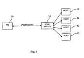
- a client device 10 connects to multiple hosts 12 via a KVM switch 14.
- the KVM switch 14 is physically attached to the hosts 12 that it is controlling, thus defining the set of hosts 12 that the switch 14 (and therefore the connecting client 10) can control.
- the client device 10 is a personal computer, and a relatively heavyweight device (in terms of processing capability) is required in the prior art KVM systems, such as the one shown in Figure 1 .
- the switch 14 If there is a need to add further hosts 12 (either by hosts becoming active or newly connected) and/or to remove hosts (hosts becoming inactive or disconnected) then this is detected by the switch 14, which can change the group membership details. These details are presented to the client 10, as requested, to allow selection of the host 12 to which the client wishes to connect.
- the switch 14 controls access to this group of hosts 12, usually requiring credentials from the client device 10 before allowing access.
- the protocol running over the IP network may be proprietary to the specific KVM switch vendor, or may be an open protocol such as VNC.
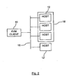
- FIG. 2 An example embodiment of the invention is shown in Figure 2 , in which a lightweight client device 10 is connected to hosts 12 via an IP network 16 (such as a local Intranet or wide area Internet).
- the system shown in Figure 2 comprises the KVM client device 10 and a plurality of host devices 12, and is for handling a connection between the client device 10 and the plurality of host devices 12.
- the KVM client 10 is directly connected to the hosts 12, and may have connectivity to hosts 12 it does not want (or is not allowed) to control.
- the KVM client 10 has less functionality than a full PC.
- the client device 10 may comprise a networked keyboard, video display and mouse using a NIVO device available from DisplayLink, Inc.
- the KVM client device 10 may allow the user to enter the name and/or address of one of the hosts 12 to be controlled, and send a message to that host requesting service. From this point on, the hosts 12 can control the session and the switching functionality. As an alternative, the hosts 12 may look for the KVM client 10 instead, and the first host 12 that finds the KVM client 10 connects to that KVM client 10. Alternatively, protocols such as DHCP may be used to direct the KVM client 10 to a default host 12, which may then redirect the KVM client 10 to another host 12 specific to that KVM client 10. For example, the KVM client 10 may first connect to the gateway address on the network 16, or to a named server, or to a host 12 specified in response to a domain name request. Alternatively, the KVM client 10 may first connect to a predetermined host 12.
- the system of Figure 2 supports various functions such as group selection, with a group 18 being shown in the Figure.
- the selected host 12 may present a list of other available hosts 12 (the list may be subject to access policy/configuration) to the client device 10.
- the client 10 sends back key/mouse presses selecting a desired host 12. This information is distributed to the relevant host 12.
- the switching operation delivered by the system allows the client device 10 to send (via a mechanism such as a hotkey press) a message to the host 12 requesting a switch.
- the host 12 relinquishes control and the next host 12 in the group list takes over.
- hosts 12 can then be added and/or deleted. This process can be carried out manually from the client device 10 end of the system, or hosts themselves, can be logically added to groups. In respect of any failure in the system, if a host 12 fails to take over control of the client device 10, a different host 12 from the failed host 12 must detect the lack of connection to the client device 10 and establish a connection itself. All other hosts 12, in this event, would update the group list.
- this system also scales to large numbers of hosts 12 more cheaply because as many hosts 12 may be added to the network 16 as required, each running the host control software but otherwise being standard networked PCs. Also, the hosts 12 may be distributed as widely as the network technology allows, which may comprise different rooms or even different buildings within the same local area network, all of which can still function without the need for any local switching hardware of the type required in prior art systems.
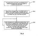
- the generalised method of handling the connection between the client device 10 and the plurality of host devices 12 is summarised in Figure 3 .
- the method comprises the first step, S1 of connecting the client device 10 to a host device 12 of the plurality of host devices 12.
- This connection can be initiated from either end, depending upon the configuration of the overall system.
- the client device 10 could connect to a known host 12 either directly, or through the mediation of a network management component.
- a specific host (such as the host 12' of Figure 2 ) could connect directly to the client device 10, which again reduces the complexity needed on the client side.
- step S2 there is the transmission of a message from the client device 10 to the connected host device 12, the message requesting transferring the connection to a different host device 12.
- This message may be a specific instruction to switch to a named host device, or may be a generalised instruction that the client device 10 wishes to switch. If the message is a simple instruction to switch, then the host replies with a list of currently available hosts and the client device must execute a choice which is then transmitted back to the currently connected host 12, as shown at step S2a.
- the connected host device 12 disconnects the connection to the client device 10, at step S3 and the new host 12 will connect to the client device 10 (step S4). All of the switching is handled at the host end of the system, via a distributed algorithm managed by the host devices.
- One embodiment of this algorithm is for the connected host device to signal to the new host that it must connect to the client device 10 in the near future. The currently connected host then drops its connection and the new host has responsibility for connecting to the client device 10.
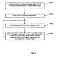
- FIG. 4 shows a more detailed embodiment of the process of managing the connection between the client device 10 and the hosts 12.
- the KVM client 10 has a fixed IP address, that all controllable hosts 12 are configured with this address, and that the hosts 12 initiate the connections to the client device 10.
- step S41 the initialisation occurs. All of the hosts 12 poll the fixed IP address of the client 10 for a response indicating that the client 10 is connected and free. As a result the KVM client 10 is connected. The first host 12 to detect the client 10 makes the connection. All of the other hosts 12 are then prevented from making a connection, but continue polling (step S42).
- step S43 If the user wishes to change host, then the user presses a key combination indicating that they wish to change host 12 (step S43).
- the connected host 12 receives a message corresponding to the key press and relinquishes control for long enough that another polling host 12 will detect the free client 10 and make a connection.
- the relinquishing host 12 then starts polling again.
- the first host 12 to detect the free client 10 initiates the connection to the client 10.
- FIG. 5 An alternative to Figure 4 is shown in the flowchart of Figure 5 .
- the assumed pre-conditions of this embodiment are that the KVM client 10 is able to initiate connections, that the KVM client 10 can have dynamic IP address but needs to know/find out/request from the user the IP address of at least one controllable host, and that the hosts 12 collaborate to provide more controlled switching.
- the KVM client 10 asks the user for an IP address/name of a host 12 to be controlled.
- the KVM client 10 connects directly to the host (step S52).
- the user wishes to change host 12, they send a message to the host 12 to which they are currently connected, and that host 12 responds and presents a menu of the other hosts 12 in group, at step S53.
- the user selects a new host 12.
- the KVM client 10 drops the connection to the old host 12 and initiates a connection to a new host 12.
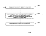
- a third embodiment of the process is shown in the flowchart of Figure 6 .
- the assumed pre-conditions of this embodiment are the same as the previous embodiment except that just one of the hosts 12 provides the switching role.
- the KVM client 10 is configured with the address of this host 12.
- the KVM client 10 connects to the designated switching host 12.
- This host 12 presents a menu of the other hosts 12 in the group.
- the user selects the host 12 to which they wish to connect.
- the KVM client 10 drops the connection to the switching host 12 and initiates the connection to the new host 12. If at any time the user wishes to change to another host, then the user presses the hotkey to change host, as shown at step 563.
- the KVM client 10 may comprise multiple USB interfaces, and connect to multiple hosts 12 using USB connections.
- the KVM client 10 may contain switching hardware to connect to a first (default) USB host 12, and reconnect to other hosts 12 under the control of the first USB host 12, or the currently connected USB host 12.
Landscapes
- Engineering & Computer Science (AREA)
- Computer Networks & Wireless Communication (AREA)
- Signal Processing (AREA)
- Computer And Data Communications (AREA)
- Communication Control (AREA)
- Two-Way Televisions, Distribution Of Moving Picture Or The Like (AREA)
Abstract
Description
- This invention relates to a method of handling a connection between a client device and a plurality of host devices, and the system comprising the client device and the plurality of host devices. The invention provides a distributed algorithm for KVM switching.
- In some computing environments, a single interface will connect to multiple computers. In the simplest case, a user may have a single keyboard, mouse and display device and have two computers running at the same time. A switch is placed between the user's interface devices (keyboard, mouse and display device) and the two computers, which determines which computer is currently connected to the interface devices. In more complicated systems that embody the same principal, a single interface may connect remotely via a wide area network to multiple computers in a remote location.
-
US 2005/0066106 discloses an input/output unit access switching system and method that are implemented on a plurality of servers respectively having a baseboard management controller and an intelligent platform management system. The servers are connected to a switching device, itself connected to a set of I/O devices such as keyboard, mouse, and monitor. - KVM (Keyboard, Video, Mouse) is a term describing the ability to control multiple hosts from a single "terminal" (KVM). The keyboard, video and mouse are connected to a KVM switch which determines which of the host devices these client devices are controlling. There is an agreed method by which the KVM switch is signalled in order to execute the decision to switch to connection to another host (for example via a hotkey on the keyboard).
- In a traditional IP KVM environment, the KVM switch is physically attached to the hosts it is controlling, thus defining the set of hosts that the switch (and connecting clients can control). Adding hosts (hosts becoming active or connected) and removing hosts (hosts becoming deactive or disconnected) is detected by the switch which can change the group membership details. The switch controls access to this group of hosts, usually requiring credentials from the client before allowing access. The protocol running over the IP network may be proprietary to the specific KVM switch vendor, or may be an open protocol such as VNC.
- Improvements in KVM switching have been proposed. For example, United States of America Patent Application Publication
US 2006/0123182 discloses a distributed KVM and peripheral switch. This Publication relates to a system and method for switching keyboard and mouse devices and video displays, as well as USB peripheral devices, between USB hosts and video sources over extended distances. There is described a distributed KVM and peripheral switch, where a USB keyboard and mouse is emulated to the host interfaces of the KVM and peripheral switch and a USB host is emulated to keyboard and mouse interfaces of the KVM and peripheral switch. In addition, the keyboard, mouse, display and peripheral devices are separated from the hosts and video sources by a non-USB communications channel. The principal disadvantage of the system disclosed in this Publication is that all routing and addressing is carried out by a separate master controller. - It is therefore an object of the invention to improve upon the known art.
- According to a first aspect of the present invention, there is provided a method of handling a connection between a KVM client device and a plurality of host devices, the method providing a distributed algorithm for KVM switching and comprising connecting the client device to a host device of the plurality of host devices, transmitting a message from the client device to the connected host device, the message requesting transferring the connection to a different host device, the connected host device disconnecting the connection to the client device, and the different host device connecting to the client device.
- According to a second aspect of the present invention, there is provided a system comprising a KVM client device and a plurality of host devices, and for handling a connection between the client device and the plurality of host devices and for providing a distributed algorithm for KVM switching, wherein the system is arranged to connect the client device to a host device of the plurality of host devices, the client device is arranged to transmit a message to the connected host device, the message requesting transferring the connection to a different host device, the connected host device is arranged to disconnect the connection to the client device, and the different host device is arranged to connect to the client device.
- Owing to the invention, it is possible to provide a new method for switching between hosts, using a distributed algorithm, and relying on the hosts themselves to control which has the current connection to the client device (the KVM). It is suitable only for scenarios where it is possible, or permitted to install software on all of the hosts required to be controlled by the client device. The terminal may be a networked KVM client, for example a keyboard, video display and mouse connected to a NIVO device available from DisplayLink, Inc.
- The invention solves the problem of creating a KVM scenario at minimal cost. Traditional IP KVM solutions require a KVM switch at the host end, and a fully functional computer at the client end running a "viewer" and other software to enable the connection and control of the KVM switch. The solution provided by the invention requires no switch (the switching function is in the hosts) and minimal hardware to connect the KVM to the network. The control of KVM switching is usually performed by a central switch. This approach is novel by proposing a distributed algorithm that performs the same functionality without the need for centralised arbitration.
- Known IP KVM systems rely on a central switch to control the access of the client device to the host systems. The approach of the invention uses the hosts themselves to perform the switching, reducing cost. In one embodiment, the switching function could be in the KVM client itself, but this increases the complexity, and probably, cost of the client device. For example, a standard PC could be used as the KVM client, but this would lose the cost advantages of using a NIVO.
- In the decentralised model utilised by this invention, the KVM client is directly connected to the hosts, and may have connectivity to hosts it does not want (or is not allowed) to control. In this model, the KVM client may have less functionality than a full PC, for example it may comprise a networked keyboard, video display and mouse using a NIVO device available from DisplayLink, Inc.
- Initialisation: the KVM client may allow the user to enter the name/address of one of the hosts to be controlled, and send a message to that host requesting service. From this point on, the hosts can control the session and the switching functionality. As an alternative, the hosts may look for the KVM client instead, and the first host that finds the KVM client connects to that KVM client.
- In one embodiment, the step of connecting the client device to a host device of the plurality of host devices is initiated by the client device. In a second embodiment, the step of connecting the client device to a host device of the plurality of host devices is initiated by a host device. Either there is stored, at the client device, an address of a host device (or some network management component), this address being used when connecting the client device to a host device, or when the address of the client device is stored at the host devices and there is polling of the client device by one or more host devices, the polling used when connecting the client device to a host device.
- Advantageously, the connection process further comprises receiving the message from the client device at the connected host device, the message requesting transferring the connection to a different host device, and transmitting a message from the connected host to the client device detailing the other hosts in the plurality of hosts. This allows the client device to see which hosts are connected to the system, and then choose the actual host to which the client device wishes to connect. The user, via the client device will select a different host and the currently connected host will disconnect and hand over to the new host. All of the handover is handled at the host end of the system, but there is no hardware switch carrying out the change in host.
- Preferably the methodology further comprises, following the connected host device disconnecting the connection to the client device, transmitting a message from the disconnected host device to the different host device, the message instructing the different host device to connect to the client device. In this embodiment, the disconnected host instructs the new host to connect to the client device, as a way of ensuring the new connection, without any intelligent behaviour on the client side. This supports a thin client being used as the user interface to the virtual KVM system.
- Embodiments of the present invention will now be described, by way of example only, with reference to the accompanying drawings, in which:-
-
Figure 1 is a schematic diagram of a prior art system, -
Figure 2 is a schematic diagram of a system according to a first embodiment of the invention, -
Figure 3 is a flowchart of a generalised method of operating the system ofFigure 2 , and -
Figures 4 to 6 are respective flowcharts of more detailed methods of operating the system ofFigure 2 . - In a traditional KVM environment, as shown in
Figure 1 , aclient device 10 connects tomultiple hosts 12 via aKVM switch 14. TheKVM switch 14 is physically attached to thehosts 12 that it is controlling, thus defining the set ofhosts 12 that the switch 14 (and therefore the connecting client 10) can control. Theclient device 10 is a personal computer, and a relatively heavyweight device (in terms of processing capability) is required in the prior art KVM systems, such as the one shown inFigure 1 . - If there is a need to add further hosts 12 (either by hosts becoming active or newly connected) and/or to remove hosts (hosts becoming inactive or disconnected) then this is detected by the
switch 14, which can change the group membership details. These details are presented to theclient 10, as requested, to allow selection of thehost 12 to which the client wishes to connect. Theswitch 14 controls access to this group ofhosts 12, usually requiring credentials from theclient device 10 before allowing access. The protocol running over the IP network may be proprietary to the specific KVM switch vendor, or may be an open protocol such as VNC. - An example embodiment of the invention is shown in
Figure 2 , in which alightweight client device 10 is connected tohosts 12 via an IP network 16 (such as a local Intranet or wide area Internet). The system shown inFigure 2 comprises theKVM client device 10 and a plurality ofhost devices 12, and is for handling a connection between theclient device 10 and the plurality ofhost devices 12. In the decentralised model used in this system, theKVM client 10 is directly connected to thehosts 12, and may have connectivity tohosts 12 it does not want (or is not allowed) to control. In this embodiment, theKVM client 10 has less functionality than a full PC. For example, theclient device 10 may comprise a networked keyboard, video display and mouse using a NIVO device available from DisplayLink, Inc. - To execute initialisation, the
KVM client device 10 may allow the user to enter the name and/or address of one of thehosts 12 to be controlled, and send a message to that host requesting service. From this point on, thehosts 12 can control the session and the switching functionality. As an alternative, thehosts 12 may look for theKVM client 10 instead, and thefirst host 12 that finds theKVM client 10 connects to thatKVM client 10. Alternatively, protocols such as DHCP may be used to direct theKVM client 10 to adefault host 12, which may then redirect theKVM client 10 to anotherhost 12 specific to thatKVM client 10. For example, theKVM client 10 may first connect to the gateway address on thenetwork 16, or to a named server, or to ahost 12 specified in response to a domain name request. Alternatively, theKVM client 10 may first connect to apredetermined host 12. - The system of
Figure 2 supports various functions such as group selection, with agroup 18 being shown in the Figure. The selectedhost 12 may present a list of other available hosts 12 (the list may be subject to access policy/configuration) to theclient device 10. Theclient 10 sends back key/mouse presses selecting a desiredhost 12. This information is distributed to therelevant host 12. The switching operation delivered by the system allows theclient device 10 to send (via a mechanism such as a hotkey press) a message to thehost 12 requesting a switch. Thehost 12 relinquishes control and thenext host 12 in the group list takes over. - It is possible to add and remove
hosts 12 from thelogical group 18 ofhosts 12. Another hotkey press from theclient device 10 can be used to request a list of available hosts from the currently connectedhost 12.Hosts 12 can then be added and/or deleted. This process can be carried out manually from theclient device 10 end of the system, or hosts themselves, can be logically added to groups. In respect of any failure in the system, if ahost 12 fails to take over control of theclient device 10, adifferent host 12 from the failedhost 12 must detect the lack of connection to theclient device 10 and establish a connection itself. Allother hosts 12, in this event, would update the group list. - Compared with the prior art arrangements, this system also scales to large numbers of
hosts 12 more cheaply because asmany hosts 12 may be added to thenetwork 16 as required, each running the host control software but otherwise being standard networked PCs. Also, thehosts 12 may be distributed as widely as the network technology allows, which may comprise different rooms or even different buildings within the same local area network, all of which can still function without the need for any local switching hardware of the type required in prior art systems. - Whereas the prior art hardware KVM switch requires individual keyboard, video and mouse ports for each host, and each host must be connected to the KVM switch via standard keyboard, video and mouse connections, both the number of hosts and the distance of each host from the KVM switch are limited by the number of ports on the KVM switch and the short length of VGA video cables. Extending the length of keyboard, video or mouse cables incurs signal quality issues, as these interfaces are not designed to run over long distances.
- The generalised method of handling the connection between the
client device 10 and the plurality ofhost devices 12 is summarised inFigure 3 . The method comprises the first step, S1 of connecting theclient device 10 to ahost device 12 of the plurality ofhost devices 12. This connection can be initiated from either end, depending upon the configuration of the overall system. For example, as discussed above, theclient device 10 could connect to a knownhost 12 either directly, or through the mediation of a network management component. Alternatively, a specific host (such as the host 12' ofFigure 2 ) could connect directly to theclient device 10, which again reduces the complexity needed on the client side. - Once the user of the client device wishes to switch to a
different host 12, then at step S2, there is the transmission of a message from theclient device 10 to theconnected host device 12, the message requesting transferring the connection to adifferent host device 12. This message may be a specific instruction to switch to a named host device, or may be a generalised instruction that theclient device 10 wishes to switch. If the message is a simple instruction to switch, then the host replies with a list of currently available hosts and the client device must execute a choice which is then transmitted back to the currently connectedhost 12, as shown at step S2a. - Once a new host has been identified, then the
connected host device 12 disconnects the connection to theclient device 10, at step S3 and thenew host 12 will connect to the client device 10 (step S4). All of the switching is handled at the host end of the system, via a distributed algorithm managed by the host devices. One embodiment of this algorithm is for the connected host device to signal to the new host that it must connect to theclient device 10 in the near future. The currently connected host then drops its connection and the new host has responsibility for connecting to theclient device 10. -
Figure 4 shows a more detailed embodiment of the process of managing the connection between theclient device 10 and thehosts 12. In this flowchart there are the assumed pre-conditions that theKVM client 10 has a fixed IP address, that allcontrollable hosts 12 are configured with this address, and that thehosts 12 initiate the connections to theclient device 10. - At step S41 the initialisation occurs. All of the
hosts 12 poll the fixed IP address of theclient 10 for a response indicating that theclient 10 is connected and free. As a result theKVM client 10 is connected. Thefirst host 12 to detect theclient 10 makes the connection. All of theother hosts 12 are then prevented from making a connection, but continue polling (step S42). - If the user wishes to change host, then the user presses a key combination indicating that they wish to change host 12 (step S43). The
connected host 12 receives a message corresponding to the key press and relinquishes control for long enough that anotherpolling host 12 will detect thefree client 10 and make a connection. The relinquishinghost 12 then starts polling again. Thefirst host 12 to detect thefree client 10 initiates the connection to theclient 10. - An alternative to
Figure 4 is shown in the flowchart ofFigure 5 . The assumed pre-conditions of this embodiment are that theKVM client 10 is able to initiate connections, that theKVM client 10 can have dynamic IP address but needs to know/find out/request from the user the IP address of at least one controllable host, and that thehosts 12 collaborate to provide more controlled switching. At step S51 (initialisation) theKVM client 10 asks the user for an IP address/name of ahost 12 to be controlled. TheKVM client 10 connects directly to the host (step S52). When the user wishes to changehost 12, they send a message to thehost 12 to which they are currently connected, and thathost 12 responds and presents a menu of theother hosts 12 in group, at step S53. Following this, at step S54, the user selects anew host 12. TheKVM client 10 drops the connection to theold host 12 and initiates a connection to anew host 12. - A third embodiment of the process is shown in the flowchart of
Figure 6 . The assumed pre-conditions of this embodiment are the same as the previous embodiment except that just one of thehosts 12 provides the switching role. TheKVM client 10 is configured with the address of thishost 12. At step S61, theKVM client 10 connects to the designatedswitching host 12. Thishost 12, at step S62, presents a menu of theother hosts 12 in the group. The user selects thehost 12 to which they wish to connect. TheKVM client 10 drops the connection to the switchinghost 12 and initiates the connection to thenew host 12. If at any time the user wishes to change to another host, then the user presses the hotkey to change host, as shown at step 563. - As a further alternative, the
KVM client 10 may comprise multiple USB interfaces, and connect tomultiple hosts 12 using USB connections. In this example, theKVM client 10 may contain switching hardware to connect to a first (default)USB host 12, and reconnect toother hosts 12 under the control of thefirst USB host 12, or the currently connectedUSB host 12.
Claims (14)
- A method of handling a connection between a keyboard, video, mouse, KVM, client device and a plurality of host devices, the method providing a distributed algorithm for KVM switching and comprisingo connecting the client device to a host device of the plurality of host devices,o transmitting a message from the client device to the connected host device, the message requesting transferring the connection to a different host device,o the connected host device disconnecting the connection to the client device, ando the different host device connecting to the client device.
- A method according to claim 1, wherein the step of connecting the client device to a host device of the plurality of host devices is initiated by the client device.
- A method according to claim 2, and further comprising storing, at the client device, an address of a host device, the address used when connecting the client device to a host device.
- A method according to claim 1, wherein the step of connecting the client device to a host device of the plurality of host devices is initiated by a host device.
- A method according to claim 4, and further comprising polling the client device by one or more host devices, the polling used when connecting the client device to a host device.
- A method according to any preceding claim, and further comprising receiving the message from the client device at the connected host device, the message requesting transferring the connection to a different host device, and transmitting a message from the connected host to the client device detailing the other hosts in the plurality of hosts.
- A method according to any preceding claim, and further comprising, following the connected host device disconnecting the connection to the client device, transmitting a message from the disconnected host device to the different host device, the message instructing the different host device to connect to the client device.
- A system comprising a keyboard, video, mouse, KVM, client device and a plurality of host devices, and for handling a connection between the client device and the plurality of host devices and for providing a distributed algorithm for KVM switching, whereino the system is arranged to connect the client device to a host device of the plurality of host devices,o the client device is arranged to transmit a message to the connected host device, the message requesting transferring the connection to a different host device,o the connected host device is arranged to disconnect the connection to the client device, ando the different host device is arranged to connect to the client device.
- A system according to claim 8, wherein the connecting of the client device to a host device of the plurality of host devices is initiated by the client device.
- A system according to claim 9, wherein the client device is arranged to store an address of a host device, the address used when connecting the client device to a host device.
- A system according to claim 8, wherein the connecting of the client device to a host device of the plurality of host devices is initiated by a host device.
- A system according to claim 11, wherein one or more host devices are arranged to poll the client device, the polling used when connecting the client device to a host device.
- A system according to any one of claims 8 to 12, wherein the connected host device is arranged to receive the message from the client device, the message requesting transferring the connection to a different host device, and to transmit a message to the client device detailing the other hosts in the plurality of hosts.
- A system according to any one of claims 8 to 13, wherein the connected host device is arranged, following the disconnection of the connection to the client device, to transmit a message to the different host device, the message instructing the different host device to connect to the client device.
Applications Claiming Priority (2)
| Application Number | Priority Date | Filing Date | Title |
|---|---|---|---|
| GB0713149A GB2450748B (en) | 2007-07-06 | 2007-07-06 | Connection between a client device and multiple host devices |
| PCT/GB2008/002305 WO2009007693A2 (en) | 2007-07-06 | 2008-07-04 | Connection between a client device and multiple host devices |
Publications (2)
| Publication Number | Publication Date |
|---|---|
| EP2171985A2 EP2171985A2 (en) | 2010-04-07 |
| EP2171985B1 true EP2171985B1 (en) | 2012-03-07 |
Family
ID=38440518
Family Applications (1)
| Application Number | Title | Priority Date | Filing Date |
|---|---|---|---|
| EP08775853A Active EP2171985B1 (en) | 2007-07-06 | 2008-07-04 | Connection between a client device and multiple host devices |
Country Status (4)
| Country | Link |
|---|---|
| EP (1) | EP2171985B1 (en) |
| AT (1) | ATE548846T1 (en) |
| GB (1) | GB2450748B (en) |
| WO (1) | WO2009007693A2 (en) |
Families Citing this family (5)
| Publication number | Priority date | Publication date | Assignee | Title |
|---|---|---|---|---|
| US10657674B2 (en) | 2016-06-17 | 2020-05-19 | Immersive Robotics Pty Ltd. | Image compression method and apparatus |
| AU2018218182B2 (en) | 2017-02-08 | 2022-12-15 | Immersive Robotics Pty Ltd | Antenna control for mobile device communication |
| AU2018373495B2 (en) | 2017-11-21 | 2023-01-05 | Immersive Robotics Pty Ltd | Frequency component selection for image compression |
| WO2019100108A1 (en) | 2017-11-21 | 2019-05-31 | Immersive Robotics Pty Ltd | Image compression for digital reality |
| CN113206798B (en) * | 2021-07-05 | 2021-09-03 | 北京简网科技有限公司 | Method, device and system for processing session flow |
Family Cites Families (9)
| Publication number | Priority date | Publication date | Assignee | Title |
|---|---|---|---|---|
| GB2326257B (en) * | 1994-04-01 | 1999-02-10 | Fujitsu Ltd | Network service system |
| US20020169967A1 (en) * | 2001-05-14 | 2002-11-14 | Sangeeta Varma | Method and apparatus for multiple token access to thin client architecture session |
| FR2843210B1 (en) * | 2002-08-02 | 2005-10-14 | Meiosys | METHOD FOR MIGRATION OF CONNECTIONS IN A MULTI-COMPUTER ARCHITECTURE, METHOD FOR PERFORMING OPERATING CONTINUITY USING THE METHOD OF MIGRATION, AND MULTI-COMPUTER SYSTEM THUS EQUIPPED |
| US20040221009A1 (en) * | 2003-03-04 | 2004-11-04 | Soronti, Inc. | Keyboard-video-mouse (KVM) loop back configuration for virtual presence architecture (VPA) |
| TWI224273B (en) * | 2003-04-10 | 2004-11-21 | Inventec Corp | Switching system for operation priority of I/O unit and method thereof |
| US7251745B2 (en) * | 2003-06-11 | 2007-07-31 | Availigent, Inc. | Transparent TCP connection failover |
| US7606929B2 (en) * | 2003-06-30 | 2009-10-20 | Microsoft Corporation | Network load balancing with connection manipulation |
| US20060123182A1 (en) * | 2004-12-07 | 2006-06-08 | Francisc Sandulescu | Distributed KVM and peripheral switch |
| US20060053212A1 (en) * | 2005-10-28 | 2006-03-09 | Aspeed Technology Inc. | Computer network architecture for providing display data at remote monitor |
-
2007
- 2007-07-06 GB GB0713149A patent/GB2450748B/en active Active
-
2008
- 2008-07-04 EP EP08775853A patent/EP2171985B1/en active Active
- 2008-07-04 WO PCT/GB2008/002305 patent/WO2009007693A2/en active Application Filing
- 2008-07-04 AT AT08775853T patent/ATE548846T1/en active
Also Published As
| Publication number | Publication date |
|---|---|
| WO2009007693A2 (en) | 2009-01-15 |
| WO2009007693A3 (en) | 2009-09-17 |
| GB0713149D0 (en) | 2007-08-15 |
| GB2450748A (en) | 2009-01-07 |
| EP2171985A2 (en) | 2010-04-07 |
| ATE548846T1 (en) | 2012-03-15 |
| GB2450748B (en) | 2010-12-29 |
Similar Documents
| Publication | Publication Date | Title |
|---|---|---|
| US20100306424A1 (en) | Connection between a client device and multiple host devices | |
| EP1880309B1 (en) | Smart-switch management module system and method | |
| KR101007356B1 (en) | Apparatus and method for establishing input/output device in virtualization system | |
| US6615272B1 (en) | Switch node for connecting a keyboard video mouse to selected servers in a interconnected switch node network | |
| EP2171985B1 (en) | Connection between a client device and multiple host devices | |
| EP1631034B1 (en) | Peer-to-peer distribution of firmware | |
| CA2650927C (en) | Methods and systems for bandwidth adaptive n-to-n communication in a distributed system | |
| US8214565B2 (en) | Communication apparatus, KVM switch and communication control method | |
| KR100452880B1 (en) | GUI based integrated remote management system for controlling power on-off and picture of the remote computer system and generating alarm signal | |
| GB2447768A (en) | Network projection system | |
| US20030065864A1 (en) | System and method supporting remote data processing system management | |
| JP4649584B2 (en) | Peripheral device driver installation system | |
| US10320663B2 (en) | Communication device, communication system, and computer program product for performing interactive communication via relay servers | |
| Cisco | Using Terminals | |
| Cisco | Using Terminals | |
| Cisco | Using Terminals | |
| Cisco | Using Terminals | |
| Cisco | Using Terminals | |
| CN110096236B (en) | Remote on-hook switching method for U disk of KVM system | |
| Cisco | Using Terminals | |
| Cisco | Using Terminals | |
| Cisco | Using Terminals | |
| EP1410598B1 (en) | Improvements relating to server systems | |
| CN101005421A (en) | Telnet control method for realizing multiple network system by single network port | |
| KR200273788Y1 (en) | Cluster system |
Legal Events
| Date | Code | Title | Description |
|---|---|---|---|
| PUAI | Public reference made under article 153(3) epc to a published international application that has entered the european phase |
Free format text: ORIGINAL CODE: 0009012 |
|
| 17P | Request for examination filed |
Effective date: 20100112 |
|
| AK | Designated contracting states |
Kind code of ref document: A2 Designated state(s): AT BE BG CH CY CZ DE DK EE ES FI FR GB GR HR HU IE IS IT LI LT LU LV MC MT NL NO PL PT RO SE SI SK TR |
|
| AX | Request for extension of the european patent |
Extension state: AL BA MK RS |
|
| 17Q | First examination report despatched |
Effective date: 20100503 |
|
| DAX | Request for extension of the european patent (deleted) | ||
| RIC1 | Information provided on ipc code assigned before grant |
Ipc: G06F 3/023 20060101ALI20101220BHEP Ipc: H04L 29/06 20060101ALI20101220BHEP Ipc: H04L 29/08 20060101AFI20101220BHEP Ipc: G06F 3/14 20060101ALI20101220BHEP |
|
| GRAP | Despatch of communication of intention to grant a patent |
Free format text: ORIGINAL CODE: EPIDOSNIGR1 |
|
| GRAS | Grant fee paid |
Free format text: ORIGINAL CODE: EPIDOSNIGR3 |
|
| RBV | Designated contracting states (corrected) |
Designated state(s): AT BE BG CH CY CZ DE DK EE ES FI FR GR HR HU IE IS IT LI LT LU LV MC MT NL NO PL PT RO SE SI SK TR |
|
| GRAA | (expected) grant |
Free format text: ORIGINAL CODE: 0009210 |
|
| AK | Designated contracting states |
Kind code of ref document: B1 Designated state(s): AT BE BG CH CY CZ DE DK EE ES FI FR GR HR HU IE IS IT LI LT LU LV MC MT NL NO PL PT RO SE SI SK TR |
|
| REG | Reference to a national code |
Ref country code: AT Ref legal event code: REF Ref document number: 548846 Country of ref document: AT Kind code of ref document: T Effective date: 20120315 Ref country code: CH Ref legal event code: EP |
|
| REG | Reference to a national code |
Ref country code: IE Ref legal event code: FG4D |
|
| REG | Reference to a national code |
Ref country code: DE Ref legal event code: R096 Ref document number: 602008013982 Country of ref document: DE Effective date: 20120503 |
|
| REG | Reference to a national code |
Ref country code: NL Ref legal event code: VDEP Effective date: 20120307 |
|
| PG25 | Lapsed in a contracting state [announced via postgrant information from national office to epo] |
Ref country code: HR Free format text: LAPSE BECAUSE OF FAILURE TO SUBMIT A TRANSLATION OF THE DESCRIPTION OR TO PAY THE FEE WITHIN THE PRESCRIBED TIME-LIMIT Effective date: 20120307 Ref country code: NL Free format text: LAPSE BECAUSE OF FAILURE TO SUBMIT A TRANSLATION OF THE DESCRIPTION OR TO PAY THE FEE WITHIN THE PRESCRIBED TIME-LIMIT Effective date: 20120307 Ref country code: NO Free format text: LAPSE BECAUSE OF FAILURE TO SUBMIT A TRANSLATION OF THE DESCRIPTION OR TO PAY THE FEE WITHIN THE PRESCRIBED TIME-LIMIT Effective date: 20120607 Ref country code: LT Free format text: LAPSE BECAUSE OF FAILURE TO SUBMIT A TRANSLATION OF THE DESCRIPTION OR TO PAY THE FEE WITHIN THE PRESCRIBED TIME-LIMIT Effective date: 20120307 |
|
| LTIE | Lt: invalidation of european patent or patent extension |
Effective date: 20120307 |
|
| PG25 | Lapsed in a contracting state [announced via postgrant information from national office to epo] |
Ref country code: LV Free format text: LAPSE BECAUSE OF FAILURE TO SUBMIT A TRANSLATION OF THE DESCRIPTION OR TO PAY THE FEE WITHIN THE PRESCRIBED TIME-LIMIT Effective date: 20120307 Ref country code: FI Free format text: LAPSE BECAUSE OF FAILURE TO SUBMIT A TRANSLATION OF THE DESCRIPTION OR TO PAY THE FEE WITHIN THE PRESCRIBED TIME-LIMIT Effective date: 20120307 Ref country code: GR Free format text: LAPSE BECAUSE OF FAILURE TO SUBMIT A TRANSLATION OF THE DESCRIPTION OR TO PAY THE FEE WITHIN THE PRESCRIBED TIME-LIMIT Effective date: 20120608 |
|
| REG | Reference to a national code |
Ref country code: AT Ref legal event code: MK05 Ref document number: 548846 Country of ref document: AT Kind code of ref document: T Effective date: 20120307 |
|
| PG25 | Lapsed in a contracting state [announced via postgrant information from national office to epo] |
Ref country code: CY Free format text: LAPSE BECAUSE OF FAILURE TO SUBMIT A TRANSLATION OF THE DESCRIPTION OR TO PAY THE FEE WITHIN THE PRESCRIBED TIME-LIMIT Effective date: 20120307 |
|
| PG25 | Lapsed in a contracting state [announced via postgrant information from national office to epo] |
Ref country code: PL Free format text: LAPSE BECAUSE OF FAILURE TO SUBMIT A TRANSLATION OF THE DESCRIPTION OR TO PAY THE FEE WITHIN THE PRESCRIBED TIME-LIMIT Effective date: 20120307 Ref country code: CZ Free format text: LAPSE BECAUSE OF FAILURE TO SUBMIT A TRANSLATION OF THE DESCRIPTION OR TO PAY THE FEE WITHIN THE PRESCRIBED TIME-LIMIT Effective date: 20120307 Ref country code: SI Free format text: LAPSE BECAUSE OF FAILURE TO SUBMIT A TRANSLATION OF THE DESCRIPTION OR TO PAY THE FEE WITHIN THE PRESCRIBED TIME-LIMIT Effective date: 20120307 Ref country code: IS Free format text: LAPSE BECAUSE OF FAILURE TO SUBMIT A TRANSLATION OF THE DESCRIPTION OR TO PAY THE FEE WITHIN THE PRESCRIBED TIME-LIMIT Effective date: 20120707 Ref country code: RO Free format text: LAPSE BECAUSE OF FAILURE TO SUBMIT A TRANSLATION OF THE DESCRIPTION OR TO PAY THE FEE WITHIN THE PRESCRIBED TIME-LIMIT Effective date: 20120307 Ref country code: SE Free format text: LAPSE BECAUSE OF FAILURE TO SUBMIT A TRANSLATION OF THE DESCRIPTION OR TO PAY THE FEE WITHIN THE PRESCRIBED TIME-LIMIT Effective date: 20120307 Ref country code: EE Free format text: LAPSE BECAUSE OF FAILURE TO SUBMIT A TRANSLATION OF THE DESCRIPTION OR TO PAY THE FEE WITHIN THE PRESCRIBED TIME-LIMIT Effective date: 20120307 Ref country code: BE Free format text: LAPSE BECAUSE OF FAILURE TO SUBMIT A TRANSLATION OF THE DESCRIPTION OR TO PAY THE FEE WITHIN THE PRESCRIBED TIME-LIMIT Effective date: 20120307 |
|
| PG25 | Lapsed in a contracting state [announced via postgrant information from national office to epo] |
Ref country code: SK Free format text: LAPSE BECAUSE OF FAILURE TO SUBMIT A TRANSLATION OF THE DESCRIPTION OR TO PAY THE FEE WITHIN THE PRESCRIBED TIME-LIMIT Effective date: 20120307 Ref country code: PT Free format text: LAPSE BECAUSE OF FAILURE TO SUBMIT A TRANSLATION OF THE DESCRIPTION OR TO PAY THE FEE WITHIN THE PRESCRIBED TIME-LIMIT Effective date: 20120709 |
|
| PLBE | No opposition filed within time limit |
Free format text: ORIGINAL CODE: 0009261 |
|
| STAA | Information on the status of an ep patent application or granted ep patent |
Free format text: STATUS: NO OPPOSITION FILED WITHIN TIME LIMIT |
|
| PG25 | Lapsed in a contracting state [announced via postgrant information from national office to epo] |
Ref country code: AT Free format text: LAPSE BECAUSE OF FAILURE TO SUBMIT A TRANSLATION OF THE DESCRIPTION OR TO PAY THE FEE WITHIN THE PRESCRIBED TIME-LIMIT Effective date: 20120307 Ref country code: DK Free format text: LAPSE BECAUSE OF FAILURE TO SUBMIT A TRANSLATION OF THE DESCRIPTION OR TO PAY THE FEE WITHIN THE PRESCRIBED TIME-LIMIT Effective date: 20120307 |
|
| 26N | No opposition filed |
Effective date: 20121210 |
|
| PG25 | Lapsed in a contracting state [announced via postgrant information from national office to epo] |
Ref country code: MC Free format text: LAPSE BECAUSE OF NON-PAYMENT OF DUE FEES Effective date: 20120731 Ref country code: IT Free format text: LAPSE BECAUSE OF FAILURE TO SUBMIT A TRANSLATION OF THE DESCRIPTION OR TO PAY THE FEE WITHIN THE PRESCRIBED TIME-LIMIT Effective date: 20120307 |
|
| REG | Reference to a national code |
Ref country code: CH Ref legal event code: PL |
|
| REG | Reference to a national code |
Ref country code: DE Ref legal event code: R097 Ref document number: 602008013982 Country of ref document: DE Effective date: 20121210 |
|
| PG25 | Lapsed in a contracting state [announced via postgrant information from national office to epo] |
Ref country code: CH Free format text: LAPSE BECAUSE OF NON-PAYMENT OF DUE FEES Effective date: 20120731 Ref country code: LI Free format text: LAPSE BECAUSE OF NON-PAYMENT OF DUE FEES Effective date: 20120731 Ref country code: ES Free format text: LAPSE BECAUSE OF FAILURE TO SUBMIT A TRANSLATION OF THE DESCRIPTION OR TO PAY THE FEE WITHIN THE PRESCRIBED TIME-LIMIT Effective date: 20120618 |
|
| REG | Reference to a national code |
Ref country code: IE Ref legal event code: MM4A |
|
| PG25 | Lapsed in a contracting state [announced via postgrant information from national office to epo] |
Ref country code: BG Free format text: LAPSE BECAUSE OF FAILURE TO SUBMIT A TRANSLATION OF THE DESCRIPTION OR TO PAY THE FEE WITHIN THE PRESCRIBED TIME-LIMIT Effective date: 20120607 Ref country code: IE Free format text: LAPSE BECAUSE OF NON-PAYMENT OF DUE FEES Effective date: 20120704 Ref country code: MT Free format text: LAPSE BECAUSE OF FAILURE TO SUBMIT A TRANSLATION OF THE DESCRIPTION OR TO PAY THE FEE WITHIN THE PRESCRIBED TIME-LIMIT Effective date: 20120307 |
|
| PG25 | Lapsed in a contracting state [announced via postgrant information from national office to epo] |
Ref country code: TR Free format text: LAPSE BECAUSE OF FAILURE TO SUBMIT A TRANSLATION OF THE DESCRIPTION OR TO PAY THE FEE WITHIN THE PRESCRIBED TIME-LIMIT Effective date: 20120307 |
|
| PG25 | Lapsed in a contracting state [announced via postgrant information from national office to epo] |
Ref country code: LU Free format text: LAPSE BECAUSE OF NON-PAYMENT OF DUE FEES Effective date: 20120704 |
|
| PG25 | Lapsed in a contracting state [announced via postgrant information from national office to epo] |
Ref country code: HU Free format text: LAPSE BECAUSE OF FAILURE TO SUBMIT A TRANSLATION OF THE DESCRIPTION OR TO PAY THE FEE WITHIN THE PRESCRIBED TIME-LIMIT Effective date: 20080704 |
|
| REG | Reference to a national code |
Ref country code: FR Ref legal event code: PLFP Year of fee payment: 9 |
|
| REG | Reference to a national code |
Ref country code: FR Ref legal event code: PLFP Year of fee payment: 10 |
|
| REG | Reference to a national code |
Ref country code: FR Ref legal event code: PLFP Year of fee payment: 11 |
|
| REG | Reference to a national code |
Ref country code: DE Ref legal event code: R079 Ref document number: 602008013982 Country of ref document: DE Free format text: PREVIOUS MAIN CLASS: H04L0029080000 Ipc: H04L0065000000 |
|
| PGFP | Annual fee paid to national office [announced via postgrant information from national office to epo] |
Ref country code: FR Payment date: 20230724 Year of fee payment: 16 Ref country code: DE Payment date: 20230620 Year of fee payment: 16 |