EP2171983B1 - Verfahren zum weiterleiten von daten in einem dezentralen datennetz - Google Patents
Verfahren zum weiterleiten von daten in einem dezentralen datennetz Download PDFInfo
- Publication number
- EP2171983B1 EP2171983B1 EP07785847A EP07785847A EP2171983B1 EP 2171983 B1 EP2171983 B1 EP 2171983B1 EP 07785847 A EP07785847 A EP 07785847A EP 07785847 A EP07785847 A EP 07785847A EP 2171983 B1 EP2171983 B1 EP 2171983B1
- Authority
- EP
- European Patent Office
- Prior art keywords
- node
- tree
- network
- path
- nodes
- Prior art date
- Legal status (The legal status is an assumption and is not a legal conclusion. Google has not performed a legal analysis and makes no representation as to the accuracy of the status listed.)
- Active
Links
Images


Classifications
-
- H—ELECTRICITY
- H04—ELECTRIC COMMUNICATION TECHNIQUE
- H04L—TRANSMISSION OF DIGITAL INFORMATION, e.g. TELEGRAPHIC COMMUNICATION
- H04L45/00—Routing or path finding of packets in data switching networks
- H04L45/22—Alternate routing
-
- H—ELECTRICITY
- H04—ELECTRIC COMMUNICATION TECHNIQUE
- H04L—TRANSMISSION OF DIGITAL INFORMATION, e.g. TELEGRAPHIC COMMUNICATION
- H04L45/00—Routing or path finding of packets in data switching networks
- H04L45/48—Routing tree calculation
-
- H—ELECTRICITY
- H04—ELECTRIC COMMUNICATION TECHNIQUE
- H04L—TRANSMISSION OF DIGITAL INFORMATION, e.g. TELEGRAPHIC COMMUNICATION
- H04L67/00—Network arrangements or protocols for supporting network services or applications
- H04L67/01—Protocols
- H04L67/10—Protocols in which an application is distributed across nodes in the network
- H04L67/104—Peer-to-peer [P2P] networks
- H04L67/1061—Peer-to-peer [P2P] networks using node-based peer discovery mechanisms
- H04L67/1065—Discovery involving distributed pre-established resource-based relationships among peers, e.g. based on distributed hash tables [DHT]
-
- H—ELECTRICITY
- H04—ELECTRIC COMMUNICATION TECHNIQUE
- H04L—TRANSMISSION OF DIGITAL INFORMATION, e.g. TELEGRAPHIC COMMUNICATION
- H04L67/00—Network arrangements or protocols for supporting network services or applications
- H04L67/01—Protocols
- H04L67/10—Protocols in which an application is distributed across nodes in the network
- H04L67/104—Peer-to-peer [P2P] networks
Definitions
- the invention relates to a method for forwarding data in a decentralized data network and to a decentralized data network.
- the invention relates to distributed data networks in which a plurality of network nodes form a first layer and a tree structure in the form of a plurality of tree nodes is distributed as a second layer to the plurality of network nodes of the first layer.
- a respective tree node is thereby characterized by a unique path in the tree structure, and each path is uniquely assigned a resource managed by at least one network node in the decentralized data network.
- resources are in particular to be understood as data which are stored in network nodes of the data network.
- the object of the invention is to provide a method for forwarding data in a decentralized data network, with which data can be efficiently routed on the basis of the infrastructure of the decentralized data network.
- an unambiguous mapping of paths of a tree structure which in each case correspond unambiguously to a tree node, is initially provided on resources managed in the decentralized data network.
- a second layer in the form of a tree structure is thus placed on a first layer, which forms network nodes of the decentralized data network.
- a request to one or more tree nodes is first specified by a path expression.
- the path expression is split into one or more consecutive path sections to forward the request, dividing the path sections into unique and ambiguous path sections.
- suitable path expressions are defined for the description of queries, which can be subdivided into unambiguous and ambiguous path sections. Instead of traversing the individual path sections node by node, a forwarding to the corresponding tree node in the first layer of the decentralized data network, by a resource is searched on the basis of the corresponding overall path.
- the invention has the great advantage that efficient search mechanisms, which are known for decentralized data networks, can be used in the forwarding of the data in the tree structure.
- the method is particularly advantageous when a peer-to-peer network is used as the decentralized data network in which a hash value is assigned to a resource with a hash function and the resources are managed via a distributed hash table , wherein each network node of the peer-to-peer network is responsible for a range of values of the hash table and is searched for resources based on the hash values.
- the use of such peer-to-peer networks on the first layer takes advantage of such networks, in particular the scalability and reliability of data routing.
- the peer-to-peer network is hereby preferably an overlay network, in particular based on any known network, such as e.g. Chord and / or Pastry and / or Tapestry and / or Kademlia.
- the resilience in forwarding the data is ensured by the fact that the decentralized data network replicates the resources managed by the network nodes one or more times, so that if a network node fails, a corresponding network node, the copies of Resources of the failed network node, replacing the failed network node.
- This data replication is used in particular in the peer-to-peer networks already described above.
- the process of the invention can be used in any area of technology.
- a particularly preferred application scenario here energy grids.
- the tree structure represents a control network for a power supply network, wherein the leaf nodes in the tree structure are assigned to energy producers which are connected to the energy supply network.
- An advantage of using the invention in the field of energy supply is that according to any criteria corresponding tree structures can be generated.
- the tree structure can be used to create a structure structured according to geographical locations of the energy producers. It is likewise possible for a structure structured according to energy types of the energy generator to be generated by the tree structure.
- suitable queries which specify geographical locations or types of energy can be generated via the tree structure in this way.
- each tree node is assigned an identity which is unique within the child nodes of a parent node of the tree structure. In this way, it is particularly easy to generate a syntax for a path, which ensures that the path according to the syntax is unique to a leaf node.
- each tree node is also assigned a node name and / or one or more attributes, the node name and / or the attributes describing properties of the tree node, in particular a geographic region and / or a power generation type.
- a unique path portion in a path expression may be determined by the number of consecutive unique specifications of tree nodes.
- the unique specification of a tree node is determined in particular by at least the respective node identity of the tree node, preferably by the node identity and the node name of the tree node.
- An ambiguous path section in a preferred embodiment, is determined by an ambiguous specification of child nodes and a parent node, the number of subsequent unique specifications of tree nodes.
- An ambiguous path section thus achieves its ambiguity by defining various child nodes, after which a unique path of tree nodes is again defined by unique specifications. The ambiguous path section ends when the series of subsequent unique specifications is interrupted.
- An ambiguous specification of child nodes may be represented, for example, by a truncation character, such as a truncation character. the character "*" can be reached. This captures all child nodes of the tree node specified in the path expression before the ambiguous specification.
- the ambiguous specification of child nodes may also specify certain types of child nodes by further including a node name and / or one or more attributes such that only those child nodes that satisfy these criteria are searched for.
- a path expression in addition to the unambiguous and ambiguous path sections described above may further comprise a broadcast path section, wherein in the processing of the broadcast path section the request tree nodes for tree nodes is forwarded to the tree nodes, which in the tree structure the tree nodes which is specified in the path expression before the broadcast path section, namely to the leaf nodes of the tree or until the next unique or ambiguous path expression occurs.
- read and / or write requests can be processed, wherein the read requests can be so-called schedule requests which periodically instruct the transmission of information according to a predetermined time scheme.
- a respective network node receiving a request adds the path of the request to the corresponding tree node in the tree or an alternate path to the request corresponding tree node associated alternative tree node and the number of tree nodes to which the request is sent from the respective network nodes, as an entry of a list within the request to be forwarded.
- This list can then be used in returning the response to determine an appropriate return route.
- care is taken that the alternate tree node is assigned to the corresponding tree node such that the physical location of the alternative tree node is proximate or within the physical region defined by the corresponding tree node is specified. This is enabled when spatial regions, such as names or attributes, are determined by the tree nodes.
- Such a choice of alternative tree nodes ensures that the response to a particularly short physical path is returned by the decentralized data network.
- the generation of a corresponding list can send back responses efficiently.
- a corresponding node does not have to keep open the data connection to the nodes to which it sends the request until the response has been received.
- a response is returned by searching in the first layer for the resources allocated to the respective paths in the list.
- a network node receiving a response to a respective request waits until it receives replies from the number of network nodes according to the corresponding entry in the list, and then sends those replies to a reply and forwards to the network node according to the previous entry in the list.
- the invention further comprises a decentralized data network, which is designed such that the data in the data network can be forwarded with the method according to the invention described above.
- the control infrastructure of a power supply network is realized by means of peer-to-peer technology, which enables self-organizing infrastructures which contain a large number of decentralized peers and are robust to peer failures.
- the peers in the embodiment described here The network nodes in the sense of the claims. It is known from the prior art, a variety of different peer-to-peer networks. The invention can be realized with any such networks.
- the robustness of peer-to-peer networks against peer failures is achieved, in particular, by replicating the resources managed by the peers in other peers, and in the event of a peer failure, the peer containing copies of the resources manages the resources of the failed peer takes over.
- the resources in the peers are managed with a distributed hash table (also called a DHT table).
- a keyword assigned to the resource is used to generate a hash value using a hash function (for example SHA1), wherein the total of the possible hash values is dynamically subdivided into value ranges and each peer is responsible for a specific value range.
- the hash value associated with the corresponding resource dynamically determines which peer is responsible for that resource because of its area of responsibility.
- resources are searched for easily on the basis of the hash values with corresponding search algorithms. Since this search for resources does not require node-by-node forwarding of data and is thus very efficient, according to the following embodiments it is used to forward requests in the power supply network.
- the utility grid is managed by a utility company, and in the embodiment described herein, the utility company manages the grid control infrastructure based on a tree structure having a plurality of tree nodes. Furthermore, there are the energy producers, which with the control infrastructure of the energy supply company are connected. The utility company uses the control infrastructure to send commands to the individual power producers and retrieve status information from the generators. In the embodiment described below, power generators are logically assigned leaf nodes of the tree through the tree structure, and the power company can address these leaf nodes through the generated tree structure.
- the utility's tree is deployed independently of the underlying hardware. Even if a corresponding computer in the underlying hardware fails, adds or removes, this tree structure remains.
- the utility can manage several different leaf structures in parallel, with each tree representing a different view of the power grid. In this way, the utility company can select the tree structure best suited for the application to control the power supply.
- Child nodes are connected to these child nodes, wherein for the child node "weather-dependent" alternative energy generators (specified by the node name “alternative-energy”) are specified, which are dependent on the weather, namely by the identities “wind” and “solar ". Similarly, as child nodes to the node with the identity “weather-independent” corresponding alternative energy generators are set, which are independent of the weather, namely by the identities "biomass” and "water”.
- the above structure thus includes four alternative energy producers, namely a wind power plant, a solar power plant, a biomass-based power plant and a hydroelectric power plant.
- two generators with the identity k1 or k2 for the region Upper Franconia are mentioned, wherein these generators are specified again by another type attribute which defines the power generation type.
- This energy generation mode is for the node with the identity k1 wind and for the node with the identity k2 biomass.
- the control infrastructure is capable of supporting so-called multicasting (i.e., routing of requests to multiple peers), and a so-called aggregation tree may also be provided with which periodic reports are sent back from the power producers to the leaf node to the utility.
- the logical tree structure provided by the invention is independent of the underlying physical infrastructure. Hardware can be added or removed without having to adjust the tree structure.
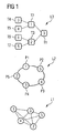
- Fig. 1 a three-layered network structure is shown, which is used in one embodiment of the method according to the invention.
- IP Internet Protocol
- the lowest layer L1 comprises hosts 1, 2, 3, 4 and 5, which are networked with each other via corresponding communication links (shown as lines).
- a peer-to-peer layer in the form of an overlay network is applied as layer L2, this layer being the first layer in the sense of the claims.
- a peer-to-peer network a ring structure with the individual peers P1, P2, P3, P4 and P5, wherein for each peer further the corresponding host according to the IP layer L1 is specified.
- the peer P1 corresponds to the host 1, the peer P2 to the host 5, the peer P3 to the host 4, the peer P4 to the host 3, and the peer P5 to the host 2.
- the layer L2 peer-to-peer network provides provide a peer in a distributed hash table with a corresponding scope for hash values.
- Distributed hash tables are structured peer-to-peer systems, with each peer responsible for a particular range of keywords, with the keywords being hashed into corresponding hash values of the hash table.
- the resource responsible peer is found by using the keyword associated with the corresponding resource.
- the data from neighboring peers are replicated here, so that a neighboring peer can take over the responsibility of a failed peer.
- the peer-to-peer layer L2 is located in Fig. 1 a corresponding tree structure, which is managed by a power company.
- the tree structure is in Fig. 1 referred to as layer L3 and corresponds to the second layer in the sense of the claims.
- the tree structure contains seven tree nodes T1 to T7, the tree node T1 representing the root node, the tree nodes T2 and T3 the nodes of an intermediate hierarchical level, and the nodes T4 to T7 leaf nodes of the tree structure.
- the individual tree nodes are implemented here as resources which are stored in the distributed hash table of layer L2.
- Each peer of layer L2 can store several tree nodes.
- the tree structure according to the layer L3 may contain more tree nodes than there are peers in the distributed hash table.
- Analogous to the layer L2 are in Fig. 1 for each tree node called the hosts of the IP layer, which store the respective tree nodes in the layer L1.
- the advantage of using a peer-to-peer system according to the layer L2 between the physical layer L1 and the tree structure L3 is that the control infrastructure of the utility company in the forwarding of queries or responses to queries, the reliability and scalability of Peer-to-peer system of layer L2 can take advantage, as will be described in more detail below.
- Fig. 2 shows a schematic representation of a specific embodiment of a tree structure in which it is illustrated how the individual energy producers interact with the energy supply company according to the tree structure.
- the tree structure contains according to Fig. 2 three further areas PG1, PG2 and PG3, which combine individual servers S of different power producers PG1, PG2 and PG3.
- the individual areas PG1, PG2 and PG3 are in this case in the tree structure CI respectively individual leaf nodes T4, T5 and T7 assigned to the area within the individual power generator in the tree structure CI is not visible. This is because the servers within a power generator are not used to forward / route requests to other power generators and therefore do not need to be resolved in the tree structure.
- VPN Virtual Private Network
- the utility company operates in the scenario of Fig. 2 as a so-called client, which can direct requests to the tree structure and can receive corresponding responses to the requests.
- Such inquiries are in Fig. 2 denoted as Q and the corresponding responses as R.
- the requests Q are signed by the utility, and the peers in the peer-to-peer network can verify the signature using the utility's public key in the VPN network. By not forwarding unsigned messages in the tree, security is further enhanced.
- the tree structure used according to the invention ensures routing of data within this tree structure, the tree structure being a virtual structure physically distributed among the peers operated by the utility and the servers of the power producers.
- the routing used in the embodiment described here requires the information about which part of the tree the peer-to-peer network can be accessed and which part is at the servers of the individual power producers.
- the separation between tree nodes in the area of the individual energy producers and tree nodes, which are managed by the energy supply company, is achieved by so-called. Name trees.
- the part of the tree structure that lies on the peers of the utility company is grouped under the namespace of the utility company, whereas the subtrees with the servers S within the individual power producers PG1, PG2 and PG3 are grouped under the namespaces of the power producer.
- the tree nodes of the individual energy producers are not mapped to the peer-to-peer network because the individual energy producers can define their own data structures under their namespace.
- a respective power generator PG1, PG2 or PG3 is not resolved, but only represented by a corresponding leaf node T4, T5 or T7 of the control infrastructure CI, which access to the power generators takes place via these leaf nodes. Since the individual servers S of the power producers do not benefit from the reliability and scalability of the peer-to-peer network, the proprietary data structure of the power producers should be kept as small as possible and all data structures used by more than one power producer should be defined in the namespace of the energy supply company.
- the path starts at a node named node1 and identity id1, and then continues to a child node named node2 and id2.
- the path then leads to further nodes, which are not further specified in the example.
- the last node in the expression is then the tree node specified with this path. Due to the tree structure always exists a unique association between a tree node and the path to the tree node.
- the path expressions just described are used as keywords for generating the corresponding hash values in the distributed hash table, the hash value again defining the peer on which the corresponding tree node is stored as a resource.
- query expressions are used which, unlike the path expressions, do not necessarily have to be unique. It is thus possible that there are different ways to address the same resources in the tree structure.
- Multicasts are used to address multiple child nodes from a parent node.
- the first type is similar to a singlecast, but uses a different attribute than the id id.
- the Type attribute is specified by the multicast.
- any attributes are omitted, and the multicast is specified only by the name of the tree node, ie the multicast is / node. In this way, all child nodes are addressed, which have the name node.
- the third type of multicast is the truncation character / *, which can be used to address all children of a parent node regardless of their name.
- Broadcasts are specified by the character // in the embodiment described herein, and they are used to transmit / broadcast the request to the entire subtree specified in the request before the broadcast character //.
- the individual query expressions set forth above may be further distinguished according to three different types of queries, namely the query types Read, Write and Schedule. Which type of query is present can be specified by a corresponding variable or a corresponding flag in the query.
- Write requests can be used to send control messages to the power generators.
- a utility company may send a write request to notify all energy producers based on biomass of generating energy to increase their energy output.
- the reply message to write requests contains the data of the corresponding power generators after the corresponding update of their operation, i. after increasing the energy output.
- the utility company does not detect successful updates by comparing the data in the response message with the expected values.
- Read requests are used to read data from one or more power generators. Read requests are implemented as a special case of write requests, with the value to be written set to zero. In this way, the routing infrastructure according to the invention does not have to distinguish between read and write requests.
- Schedule requests are used to periodically query reports. For example, if a utility company wishes to periodically determine the current capacity status of certain power producers, a schedule request will be sent to the appropriate power producers, instructing power producers to do so in accordance with this request to report their capacity at fixed intervals to the utility company.
- the control infrastructure handles the schedule requests in the embodiment described herein in the same way as the read requests except that no single response message is sent, but periodically replies are sent out periodically.
- the underlying decentralized peer-to-peer infrastructure is used for routing, according to this infrastructure using the path expressions and the corresponding Hash values can be jumped directly to any position in the tree without going through the nodes individually.
- This efficient routing is achieved by forming path sections in the form of so-called "chunks" in the path expressions of the requests.
- the path expression is first divided into a first part and a second part, wherein the first part falls under the namespace of the power company and the second part addresses the data of the individual power producers.
- the routing is described using the example of the first part of the path expression. The interaction of the utility company's leaf nodes with the power producer's servers is not visible to the routing algorithm described here.
- the path expression is decomposed into so-called chunks.
- the first chunk starts at the beginning of the path expression with the corresponding root node and spans the number of consecutive singlecasts. This means that the chunk ends at the singlecast, which is immediately followed by a multicast or a broadcast. This chunk thus corresponds to a clear path expression in the sense of Claims.
- the request contains no broadcasts or multicasts, the request consists of a single chunk in the form of a unique path section. With this single chunk, the corresponding hash value of the path expression in the distributed hash table can then be addressed immediately and jumped directly to the corresponding node.
- the chunk of a single multicast in combination with the subsequent singlecast and the chunk of a single broadcast exist.
- the following expression shows an example containing all three types of chunks, the chunks being numbered 1, 2 and 3.
- the chunk 1 is followed by the chunk 2, which is an ambiguous path expression in the sense of the claims and is a combination of a single multicast and the amount of subsequent singlecasts, followed in the example above, only a single single cast.
- the third chunk 3 is a broadcast in the above example.
- Chunk 3 all types of chunks can be summarized, which do not belong to the group of consecutive single chunk Chunk 1 or to the group of the combination of multicast and successive single casts.
- An example of this chunk category would also be, for example, a multicast expression / *, followed by a chunk in the form of the above chunk 2.
- the above chunk 1 consists of two consecutive singlecasts. It represents a unique path expression that can be addressed directly according to the distributed hash table without having to rout node by node through the tree structure.
- Chunk 3 is a broadcast // in the above example. If necessary, it could also be a single mulitcast / *, if the multicast is followed by a chunk 2 or a chunk 3.
- the routing node is made node by node, ie the corresponding peer in the peer-to-peer network addresses all child nodes and forwards the request to all Peers that manage the child nodes. Subsequently, starting from the found child nodes, the next child nodes are again searched for and the request forwarded to these child nodes.
- the routing method described above processes single-casts recursively, whereas broadcasts and multicasts are processed in parallel.
- Fig. 3 the routing is clarified again by means of an example.
- a distribution of tree nodes with node names n1, n2, n3 and n4 and corresponding (only partially) identified identities a, x, y and c is shown by way of example.
- a tree structure is created which begins with a root node named n1 on peer P6, to which two child nodes with the names n2 connect to the peers P1 and P5.
- n1 root node
- peer P6 For the child node on the peer P1, there then exists another child node with the name n3 on the peer P2, and this further child node in turn has a child node with the name n4 on the peer P1.
- the root node on peer P6 has another child node named n2 on peer P5, and this child node has another child node named n3 on peer P4.
- n2 on peer P5 has another child node named n2 on peer P5
- n3 on peer P4 has another child node named n4 on peer P3 and P5 join this child node.
- the sequence of a request is clarified, which is composed of the chunks c1, c2 and c3.
- the distributed hash table is thus used to jump to the peer P6 according to step S1.
- This is followed by a chunk c2 as a combination of a multicast and a singlecast. All possible paths are determined which are possible according to this ambiguous chunk c2.
- the path expressions may be routed directly to the corresponding peers, as represented by steps S2 and S3 in FIG Fig. 3 is indicated.
- Chunk c2 is followed by chunk c3 in the form of a broadcast.
- all nodes following the tree structure are routed further, as in FIG Fig. 3 is indicated by the steps S4, S5 and S6, respectively, which lead to the corresponding child nodes stored on the peers P1, P5 and P3, respectively.
- each route message contains all the information needed to process the message.
- a so-called back route list is sent together with each routing message. This list is generated by each peer receiving a request adding the following to the list: the path expression up to the addressed tree node on the respective peer and the number of peers which will be the next hops in the case of a broadcast or multicast -Austuris be addressed.
- the above back route list is retransmitted upon returning a response to a request in the response message.
- each peer receiving a response message can then extract the path to the next hop from the list and forward the response there.
- a peer who receives an answer knows how many peers he addressed when making the appropriate request has, because that number is in the back-route list. Now, when a peer receives a response message, that peer waits until it has received responses from the appropriate number of peers on which it has also sent the request. Then, as an aggregated result, the set of all responses is forwarded to the next hop according to the previous entry in the back route list. If necessary, a timeout can be used to prevent the failure of a single peer blocking the overall result.
- a timeout flag is set indicating that the result is not complete, and the path expression of the tree node that lacks the response is added in the forwarded response message to indicate which part of the Result is missing.
- the peer responsible for the first chunk in a request is also the last peer addressed when returning the response. This peer finally aggregates the overall responses of the relevant addressed subtree and returns the result to the utility company.
- each peer can process each response message without requiring knowledge of the original route of the request.
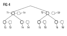
- the possibility of optimizing routing distances is created in a special embodiment of the invention. This can be accomplished by having a peer publish an alternate node in the form of a shadow node in the distributed hash table for each tree node for which it is responsible.
- the shadow node is here chosen such that the physical location where the shadow node is stored is close to the region represented by the tree node for which the corresponding shadow node was created.
- Fig. 4 shows by way of example the generation of shadow nodes in a tree structure according to the invention.
- a respective shadow node T1 ', T2', T3 ', T4', T5 'and T6' is deposited, wherein the generation of the shadow nodes is achieved by publishing a corresponding resource in a peer, which in a region specified by the respective leaf node.
Landscapes
- Engineering & Computer Science (AREA)
- Computer Networks & Wireless Communication (AREA)
- Signal Processing (AREA)
- Data Exchanges In Wide-Area Networks (AREA)
Description
- Die Erfindung betrifft ein Verfahren zum Weiterleiten von Daten in einem dezentralen Datennetz sowie auf ein dezentrales Datennetz.
- Die Erfindung bezieht sich auf dezentrale Datennetze, bei denen eine Vielzahl von Netzknoten eine erste Schicht bildet und eine Baumstruktur in der Form einer Mehrzahl von Baumknoten als eine zweite Schicht auf die Vielzahl von Netzknoten der ersten Schicht verteilt ist. Ein jeweiliger Baumknoten wird dabei durch einen eindeutigen Pfad in der Baumstruktur charakterisiert, und jedem Pfad ist eindeutig eine von wenigstens einem Netzknoten verwaltete Ressource in dem dezentralen Datennetz zugewiesen. Unter Ressourcen sind hierbei insbesondere Daten zu verstehen, welche in Netzknoten des Datennetzes gespeichert sind.
- Durch die Abbildung einer Baumstruktur auf dezentrale Datennetze könne Steuer- und Diagnosedaten von technischen Systemen in geeigneter Weise durch das Netz geleitet werden. Aus dem Stand der Technik ist es hierbei bekannt, dass sog. verteilte XML-Bäume (XML = Extensible Markup Language) auf bestimmte IP-Adressen verteilt werden. Die einzelnen Knoten in dem XML-Baum können mit entsprechenden Anfragen in der Form von XQueries angesprochen werden. Die bekannten Verfahren werden insbesondere zur Bereitstellung eines verteilten Content-Management-Systems verwendet und dienen nicht zum Weiterleiten von Daten in einem Routing-Verfahren.
- In den Druckschriften [1], [2], [3] und [4] wird die Suche nach Pfadausdrücken in XML-Dokumenten bzw. XML-Dokument-Fragmenten innerhalb eines dezentralen Datennetzes beschrieben. Die in diesen Druckschriften offenbarten Verfahren tei len die gesuchten Pfadausdrücke nicht in eindeutige und mehrdeutige Pfadabschnitte auf.
- Aufgabe der Erfindung ist es, ein Verfahren zum Weiterleiten von Daten in einem dezentralen Datennetz zu schaffen, mit dem auf der Basis der Infrastruktur des dezentralen Datennetzes effizient Daten geroutet werden können.
- Diese Aufgabe wird durch die unabhängigen Patentansprüche gelöst. Weiterbildungen der Erfindung sind in den abhängigen Ansprüchen definiert.
- In dem erfindungsgemäßen Verfahren wird zunächst eine eindeutige Abbildung von Pfaden einer Baumstruktur, welche jeweils eindeutig einem Baumknoten entsprechen, auf in dem dezentralen Datennetz verwaltete Ressourcen bereitgestellt. Auf der Basis dieser Struktur wird somit auf einer ersten Schicht, welche Netzknoten des dezentralen Datennetzes bildet, eine zweite Schicht in der Form einer Baumstruktur aufgesetzt. Ein effizientes Weiterleiten einer Anfrage in einer derartigen Struktur wird erfindungsgemäß wie folgt erreicht:
- Eine Anfrage an einen oder mehrere Baumknoten wird zunächst durch einen Pfadausdruck spezifiziert. Der Pfadausdruck wird zum Weiterleiten der Anfrage in einen oder mehrere aufeinander folgende Pfadabschnitte aufgeteilt, wobei die Pfadabschnitte in eindeutige und mehrdeutige Pfadabschnitte unterteilt werden.
- Das Weiterleiten der Anfrage zu Beginn des Pfadausdrucks oder vom Ende eines jeweiligen Pfadabschnitts (d.h. vom Baumknoten am Endes des Pfadabschnitts) zu dem Baumknoten am Ende des nächsten Pfadabschnitts (welcher der erste Pfadabschnitt bei Beginn des Pfadausdrucks ist) wird dadurch erreicht, dass
- i) für einen eindeutigen nächsten Pfadabschnitt basierend auf dem beim Wurzelknoten der Baumstruktur beginnenden Gesamtpfad bis zum Baumknoten am Ende des nächsten Pfad abschnitts die diesem Gesamtpfad zugewiesene Ressource in der ersten Schicht gesucht wird;
- ii) für einen mehrdeutigen nächsten Pfadabschnitt alle möglichen nächsten Pfadabschnitte gemäß dem mehrdeutigen Pfadabschnitts ermittelt werden und für jeden möglichen nächsten Pfadabschnitt basierend auf dem beim Wurzelknoten der Baumstruktur beginnenden Gesamtpfad bis zum Baumknoten am Ende des möglichen nächsten Pfadabschnitts die diesem Gesamtpfad zugewiesene Ressource in der ersten Schicht gesucht wird.
- In dem erfindungsgemäßen Verfahren werden geeignete Pfadausdrücke zur Beschreibung von Anfragen definiert, welche in eindeutige und mehrdeutige Pfadabschnitte unterteilt werden können. Anstatt die einzelnen Pfadabschnitte nunmehr Knoten für Knoten zu durchlaufen, erfolgt eine Weiterleitung zu dem entsprechenden Baumknoten in der ersten Schicht des dezentralen Datennetzes, und zwar indem eine Ressource auf der Basis des entsprechenden Gesamtpfads gesucht wird.
- Die Erfindung hat den großen Vorteil, dass effiziente Such-Mechanismen, welche für dezentrale Datennetze bekannt sind, bei der Weiterleitung der Daten in der Baumstruktur eingesetzt werden können. Besonders vorteilhaft ist das Verfahren hierbei dann, wenn als dezentrales Datennetz ein Peer-to-Peer-Netz eingesetzt wird, bei dem einer Ressource mit einer Hash-Funktion ein Hash-Wert zugewiesen wird und die Verwaltung der Ressourcen über eine verteilte Hash-Tabelle erfolgt, wobei jeder Netzknoten des Peer-to-Peer-Netzes für einen Wertebereich der Hash-Tabelle zuständig ist und nach Ressourcen auf der Basis der Hash-Werte gesucht wird. Durch die Verwendung von solchen Peer-to-Peer-Netzen auf der ersten Schicht macht man sich die Vorteile solcher Netze, insbesondere die Skalierbarkeit und Verlässlichkeit beim Routing der Daten, zu Nutze. Das Peer-to-Peer-Netz ist hierbei vorzugsweise ein Overlay-Netz, insbesondere basierend auf einem beliebigen bekannten Netz, wie z.B. Chord und/oder Pastry und/oder Tapestry und/oder Kademlia. Die unterhalb dieses Overlay-Netzes liegende Schicht kann eine beliebige Schicht sein, vorzugsweise wird hierbei ein IP-Netz (IP = Internet Protocol) verwendet.
- Gemäß einer besonders bevorzugten Ausführungsform des erfindungsgemäßen Verfahrens wird die Ausfallsicherheit beim Weiterleiten der Daten dadurch gewährleistet, dass das dezentrale Datennetz die von den Netzknoten verwalteten Ressourcen ein oder mehrere Male repliziert, so dass beim Ausfall eines Netzknotens ein entsprechender Netzknoten, der Kopien der Ressourcen des ausgefallenen Netzknotens enthält, den ausgefallenen Netzknoten ersetzt. Diese Datenreplikation wird insbesondere in den bereits oben beschriebenen Peer-to-Peer-Netzen eingesetzt.
- Das erfindungsgemäße Verfahren kann in beliebigen Bereichen der Technik eingesetzt werden. Ein besonders bevorzugtes Anwendungsszenario sind hierbei jedoch Energieversorgungsnetze. Hierbei stellt die Baumstruktur ein Steuerungsnetz für ein Energieversorgungsnetz dar, wobei die Blattknoten in der Baumstruktur Energieerzeugern zugeordnet sind, die an das Energieversorgungsnetz angeschlossen sind. Ein Vorteil der Verwendung der Erfindung im Bereich der Energieversorgung besteht darin, dass nach beliebigen Kriterien entsprechende Baumstrukturen erzeugt werden können. Beispielsweise kann durch die Baumstruktur eine nach geographischen Orten der Energieerzeuger gegliederte Struktur geschaffen werden. Ebenso ist es möglich, dass durch die Baumstruktur eine nach Energiearten der Energieerzeuger gegliederte Struktur erzeugt wird. Je nach Anwendungsfall können auf diese Weise geeignete Anfragen, welche geographische Orte bzw. Energiearten spezifizieren, über die Baumstruktur generiert werden.
- In einer bevorzugten Ausführungsform des erfindungsgemäßen Verfahrens ist jedem Baumknoten eine Identität zugewiesen, welche innerhalb der Kindknoten eines Elternknotens der Baumstruktur eindeutig ist. Auf diese Weise kann besonders einfach eine Syntax für einen Pfad generiert werden, welche sicherstellt, dass der Pfad gemäß der Syntax eindeutig für einen Blattknoten ist.
- In einer weiteren Ausgestaltung des erfindungsgemäßen Verfahrens sind jedem Baumknoten neben einer Identität ferner ein Knotenname und/oder ein oder mehrere Attribute zugewiesen, wobei der Knotenname und/oder die Attribute Eigenschaften des Baumknotens beschreiben, insbesondere eine geographische Region und/oder eine Energieerzeugungsart.
- In besonders einfacher Weise kann ein eindeutiger Pfadabschnitt in einem Pfadausdruck durch die Anzahl an aufeinander folgenden eindeutigen Spezifikationen von Baumknoten festgelegt werden. Die eindeutige Spezifikation eines Baumknotens wird dabei insbesondere zumindest durch die jeweilige Knotenidentität des Baumknotens, vorzugsweise durch die Knotenidentität und den Knotennamen des Baumknotens, festgelegt.
- Ein mehrdeutiger Pfadabschnitt wird in einer bevorzugten Ausführungsform durch eine mehrdeutige Spezifikation von Kindknoten und eines Elternknotens die Anzahl an darauffolgenden eindeutigen Spezifikationen von Baumknoten festgelegt. Ein mehrdeutiger Pfadabschnitt erreicht seine Mehrdeutigkeit somit durch Festlegung von verschiedenen Kindknoten, wobei daran anschließend wieder ein eindeutiger Pfad von Baumknoten durch eindeutige Spezifikationen festgelegt ist. Der mehrdeutige Pfadabschnitt endet hierbei dann, wenn die Reihe an darauf folgenden eindeutigen Spezifikationen unterbrochen wird.
- Eine mehrdeutige Spezifikation von Kindknoten kann beispielsweise durch ein Trunkierungszeichen, wie z.B. das Zeichen "*" erreicht werden. Hierdurch werden alle Kindknoten des in dem Pfadausdruck vor der mehrdeutigen Spezifikation spezifizierten Baumknotens erfasst. Die mehrdeutige Spezifikation von Kindknoten kann jedoch auch bestimmte Typen von Kindknoten festlegen, und zwar indem die Spezifikation ferner einen Knotennamen und/oder ein oder mehrere Attribute umfasst, so dass nur nach solchen Kindknoten gesucht wird, welche diese Kriterien erfüllen.
- In einer weiteren Ausführungsform des erfindungsgemäßen Verfahrens kann ein Pfadausdruck neben den oben beschriebenen eindeutigen und mehrdeutigen Pfadabschnitten ferner einen Broadcast-Pfadabschnitt umfassen, wobei bei der Verarbeitung des Broadcast-Pfadabschnitts die Anfrage Baumknoten für Baumknoten an die Baumknoten weitergeleitet wird, welche in der Baumstruktur den Baumknoten folgen, der in dem Pfadausdruck vor dem Broadcast-Pfadabschnitt spezifiziert ist, und zwar bis zu den Blattknoten der Baumstruktur oder bis zum Auftreten des nächsten eindeutigen oder mehrdeutigen Pfadausdrucks.
- In einer weiteren Ausführungsform des erfindungsgemäßen Verfahrens können Lese- und/oder Schreibanfragen verarbeitet werden, wobei die Leseanfragen sog. Schedule-Anfragen sein können, welche nach einem vorgegebenen Zeitschema periodisch die Übermittlung von Informationen anweisen.
- Um in einer Variante der Erfindung ein effizientes Rück-Routing der Antworten in Bezug auf die Anfragen zu ermöglichen, fügt ein jeweiliger Netzknoten, der eine Anfrage empfängt, den Pfad der Anfrage bis zum entsprechenden Baumknoten in der Baumstruktur oder einen Alternativ-Pfad zu einem dem entsprechenden Baumknoten zugeordneten Alternativ-Baumknoten sowie die Anzahl an Baumknoten, an welche die Anfrage von den jeweiligen Netzknoten gesendet wird, als Eintrag einer Liste innerhalb der weiterzuleitenden Anfrage hinzu. Diese Liste kann dann beim Zurücksenden der Antwort verwendet werden, um eine geeignete Rückroute festzulegen. Vorzugsweise wird bei der Verwendung von Alternativ-Baumknoten in der Liste darauf geachtet, dass der Alternativ-Baumknoten derart dem entsprechenden Baumknoten zugeordnet wird, dass der physikalische Ort des Alternativ-Baumkriotens in der Nähe oder innerhalb der physikalischen Region liegt, welche durch den entsprechenden Baumknoten spezifiziert ist. Dies wird dann ermöglicht, wenn räumliche Regionen, beispielsweise über Namen oder Attribute, durch die Baumknoten festgelegt werden. Durch eine derartige Wahl von Alternativ-Baumknoten wird ein Rücksenden der Antwort auf besonders kurzem physikalischen Weg durch das dezentrale Datennetz gewährleistet.
- Wie bereits erwähnt, können durch die Generierung einer entsprechenden Liste Rückantworten effizient zurückgesendet werden. Hierbei wird insbesondere ermöglicht, dass ein entsprechender Knoten die Datenverbindung zu den Knoten, an_welche er die Anfrage sendet, nicht bis zum Empfang der Antwort offenhalten muss. Dies wird dadurch gewährleistet, dass die Antwort auf eine jeweilige Anfrage die bei der jeweiligen Anfrage erzeugte Liste enthält, wobei eine Antwort durch Suche in der ersten Schicht nach den Ressourcen, welche den jeweiligen Pfaden in der Liste zugewiesen sind, zurückgesendet wird. Um die Vollständigkeit der Antworten gemäß der Anfrage zu gewährleisten, wartet vorzugsweise ein Netzknoten, der eine Antwort auf eine jeweilige Anfrage empfängt, so lange, bis er Antworten von der Anzahl an Netzknoten gemäß dem entsprechenden Eintrag in der Liste erhält, wobei er diese Antworten dann zu einer Antwort zusammenfasst und an den Netzknoten gemäß dem vorhergehenden Eintrag in der Liste weiterleitet. Neben dem oben beschriebenen erfindungsgemäßen Verfahren umfasst die Erfindung ferner ein dezentrales Datennetz, welches derart ausgestaltet ist, dass die Daten in dem Datennetz mit dem oben beschriebenen erfindungsgemäßen Verfahren weitergeleitet werden können.
- Ausführungsbeispiele der Erfindung werden nachfolgend anhand der beigefügten Figuren detailliert beschrieben.
- Es zeigen:
- Fig. 1
- eine schematische Darstellung einer dreischichtigen Netzstruktur, welche in einer Ausführungsform des erfindungsgemäßen Verfahrens verwendet wird;
- Fig. 2
- eine schematische Darstellung einer in dem erfindungsgemäßen Verfahren verwendeten Steuerinfrastruktur eines Energieversorgungsnetzes;
- Fig. 3
- eine beispielhafte Darstellung der Verteilung von Ressourcen in einem dezentralen Datennetz und der erfindungsgemäßen Weiterleitung einer Anfrage in dem dezentralen Datennetz; und
- Fig. 4
- eine Darstellung eines Ausschnitts aus der Baumstruktur, welche die in einer Ausführungsform verwendeten Alternativ-Baumknoten beinhaltet.
- Das nachfolgend beschriebene Verfahren zur Weiterleitung von Daten in einem dezentralen Datennetz wird am Beispiel der Steuerung eines Energieversorgungsnetzes beschrieben, wobei das Verfahren jedoch allgemein auch auf beliebige andere Netze anwendbar ist.
- Heutzutage wird elektrische Leistung nicht nur von großen Energieerzeugern durch entsprechende Kraftwerke generiert, sondern es gibt immer mehr kleinere Erzeuger von alternativen Energien, wie z.B. Solarenergie, Windenergie, Energie aus Biomasse und dergleichen. Es besteht deshalb die Notwendigkeit, Energieversorgungsnetze, an welche sowohl große Energieerzeuger als auch kleine Energieerzeuger angeschlossen sind, mit Hilfe einer entsprechenden Netzstruktur geeignet zu steuern, um hierdurch die durch die Energieerzeuger generierte Leistung entsprechend den von den Haushalten benötigten Energiemengen in den unterschiedlichen Regionen anzupassen.
- In einer solchen Steuerinfrastruktur ist es beispielsweise notwendig, die Energieerzeuger auf der Basis von Biomasse darüber in Kenntnis zu setzen, dass sie ihre Energieproduktion immer dann herabsetzen sollen, wenn genug Windenergie verfügbar ist, und dass sie ihre Energieproduktion erhöhen sollen, wenn die Menge an erzeugter Windenergie sinkt. Eine entsprechende Steuerinfrastruktur muss hochskalierbar sein, da jeder einzelne Haushalt zukünftig Energieerzeugungseinheiten oder Energieverbrauchs-Regulierungseinheiten enthalten kann.
- In der nachfolgend beschriebenen Ausführungsform wird die Steuerinfrastruktur eines Energieversorgungsnetzes mit Hilfe der Peer-to-Peer-Technologie realisiert, welche selbstorganisierende Infrastrukturen ermöglicht, die eine Vielzahl von dezentralen Peers enthalten und gegenüber Ausfällen von Peers robust sind. Die Peers stellen in der hier beschriebenen Ausführungsform die Netzknoten im Sinne der Ansprüche dar. Es ist aus dem Stand der Technik eine Vielzahl von unterschiedlichen Peer-to-Peer-Netzen bekannt. Die Erfindung kann mit beliebigen solchen Netzen realisiert werden. Die Robustheit von Peer-to-Peer-Netzen gegenüber Ausfällen von Peers wird insbesondere dadurch erreicht, dass die von den Peers verwalteten Ressourcen in anderen Peers repliziert werden, wobei bei Ausfall eines Peers derjenige Peer, der Kopien der Ressourcen enthält, die Verwaltung der Ressourcen des ausgefallenen Peers übernimmt.
- In der hier beschriebenen Ausführungsform werden die Ressourcen in den Peers mit einer verteilten Hash-Tabelle (auch als DHT-Tabelle bezeichnet; DHT = Distributed Hash Table) verwaltet. Über ein der Ressource zugeordnetes Schlüsselwort wird mit Hilfe einer Hash-Funktion (z.B. SHA1) ein Hash-Wert erzeugt, wobei die Gesamtheit der möglichen Hash-Werte dynamisch in Wertebereiche unterteilt ist und jeder Peer für einen bestimmten Wertebereich zuständig ist. Durch den Hash-Wert, der der entsprechenden Ressource zugeordnet ist, wird dynamisch festgelegt, welcher Peer für diese Ressource aufgrund seines Zuständigkeitsbereichs verantwortlich ist. Mit Hilfe der verteilten Hash-Tabelle wird nach Ressourcen auf einfache Weise auf der Basis der Hash-Werte mit entsprechenden Such-Algorithmen gesucht. Da diese Suche nach Ressourcen keine knotenweise Weiterleitung von Daten erfordert und somit sehr effizient ist, wird sie gemäß den nachfolgenden Ausführungsformen zur Weiterleitung von Anfragen in dem Energieversorgungsnetz eingesetzt.
- In einem Energieversorgungsnetz sind zwei Arten von Unternehmen beteiligt. Zum einen wird das Energieversorgungsnetz durch ein Energieversorgungsunternehmen verwaltet, wobei in der hier beschriebenen Ausführungsform das Energieversorgungsunternehmen die Steuerinfrastruktur des Netzes auf der Basis einer Baumstruktur mit einer Vielzahl von Baumknoten verwaltet. Ferner existieren die Energieerzeuger, welche mit der Steuerinfrastruktur des Energieversorgungsunternehmens verbunden sind. Das Energieversorgungsunternehmen nutzt die Steuerinfrastruktur, um Befehle an die einzelnen Energieerzeuger zu senden und Statusinformation von den Erzeugern abzurufen. In der nachfolgend beschriebenen Ausführungsform werden den Energieerzeugern durch die Baumstruktur logisch Blattknoten der Struktur zugeordnet, wobei das Energieversorgungsunternehmen diese Blattknoten durch die generierte Baumstruktur ansprechen kann.
- Die Baumstruktur des Energieversorgungsunternehmens wird unabhängig von der zugrunde liegenden Hardware bereitgestellt. Selbst wenn ein entsprechender Rechner in der zugrunde liegenden Hardware ausfällt, hinzugefügt oder entfernt wird, bleibt diese Baumstruktur enthalten. Darüber hinaus kann das Energieversorgungsunternehmen mehrere unterschiedliche Blattstrukturen parallel verwalten, wobei jede Baumstruktur eine unterschiedliche Sichtweise auf das Energieversorgungsnetz wiedergibt. Auf diese Weise kann das Energieversorgungsunternehmen die am Besten für den Anwendungsfall geeignete Baumstruktur zur Steuerung der Energieversorgung auswählen.
- Ein Beispiel einer Definition einer Baumstruktur kann wie folgt lauten:
 <power-company id="...">
      <energy-type id="weather-dependent">
           <alternative-energy id="wind".../>
        <alternative-energy id="solar".../>
        ...
      </energy-type>
      <energy-type id="weather-independent">
           <alternative-energy id="biomass".../>
           <alternative-energy id="water".../>
           ...
      </energy-type>
 </power-company>
 <power-company id="...">
     <country id="de">
           <subdivision id="by">
                <region id="ofr">
                     <generator id="k1" type="wind".../>
                     <generator id="k2" type="biomass".../>
                     ...
               </region>
               ...
           </state>
           ...
     </country>
     ...
 </power company>
- /nodel[id ='id1']/node2[id='id2']/...


- [1] P. Felber, K.W. Ross, E.W. Biersack, L. Garces-Erice, G. Urvoy-Keller: "Structured Peer-to-Peer Networks: Faster, Closer, Smarter" IEEE Data Engineering Bulletin, [Online] 2005, Seiten 1-8
- [2] Gleb Skobeltsyn et al: "Efficient Processing of XPath Queries with Structured Overlay Networks" ON THE MOVE TO MEANINGFUL INTERNET SYSTEMS 2005: COOPIS, DOA, AND ODBA SE LECTURE NOTES IN COMPUTER SCIENCE; LNCS, SPRINGER, BERLIN, DE, Bd. 3761, 1. Januar 2005 (2005-01-01), Seiten 1243-1260
- [3] Li Yin et al: "eDSR: A Decentralized Service Registry for e-Commerce" E-BUSINESS ENGINEERING, 2005. ICEBE 2005. IEEE INTERNATIONAL CONFERENCE ON BEIJING, CHINA 12-18 OCT. 2005, PISCATAWAY, NJ, USA, IEEE, 12. Oktober 2005 (2005-10-12), Seiten 615-619
- [4] Bonifati et al: Storing and retrieving XPath fragments in structured P2P networks" DATA & KNOWLEDGE ENGINEERING, NORTHHOLLAND, Bd. 59, Nr. 2, 1. November 2006 (2006-11-01), Seiten 247-269
Claims (23)
- Verfahren zum Weiterleiten von Daten in einem dezentralen Datennetz, wobei eine Vielzahl von Netzknoten (P1, P2, ..., P5) des dezentralen Datennetzes eine erste Schicht (L2) bilden und Baumknoten (T1, T2, ..., T7) einer Baumstruktur (L3) als eine zweite Schicht (L3) auf die Vielzahl von Netzknoten (P1, P2, ..., P5) der ersten Schicht (L2) abgebildet sind, wobei ein jeweiliger Baumknoten (T1, T2, ..., T7) durch einen eindeutigen Pfad in der Baumstruktur (L3) charakterisiert ist und jedem Pfad eindeutig eine von wenigstens einem Netzknoten (P1, P2, ..., P5) verwaltete Ressource in dem dezentralen Datennetz (L2) zugewiesen ist, wobei eine Anfrage (Q) an einen oder mehrere Baumknoten (T1, T2, ..., T7) durch einen Pfadausdruck spezifiziert wird,
dadurch gekennzeichnet, dass- der Pfadausdruck der Anfrage (Q) in einen oder mehrere aufeinander folgende Pfadabschnitte aufgeteilt wird, wobei die Pfadabschnitte in eindeutige und mehrdeutige Pfadabschnitte unterteilt werden;- die Anfrage (Q) zu Beginn des Pfadausdrucks oder am Ende eines jeweiligen Pfadabschnitts (c1, c2, c3) zu dem Baumknoten (T1, T2, ..., T7) am Ende des nächsten Pfadabschnitts (c1, c2, c3) derart weitergeleitet wird, dassi) für einen eindeutigen nächsten Pfadabschnitt basierend auf dem Gesamtpfad in der Baumstruktur bis zum Baumknoten (T1, T2, ..., T7) am Ende des nächsten Pfadabschnitts die diesem Gesamtpfad zugewiesene Ressource in der ersten Schicht (L2) gesucht wird;ii) für einen mehrdeutigen nächsten Pfadabschnitt alle möglichen nächsten Pfadabschnitte gemäß dem mehrdeutigen Pfadabschnitt ermittelt werden und für jeden möglichen nächsten Pfadabschnitt basierend auf dem Gesamtpfad in der Baumstruktur bis zum Baumknoten (T1, T2, ..., T7) am Ende des möglichen nächsten Pfadabschnitts die diesem Gesamtpfad zugewiesene Ressource in der ersten Schicht gesucht wird. - Verfahren nach Anspruch 1, bei dem das dezentrale Datennetz ein Peer-to-Peer-Netz ist, in dem einer Ressource mit einer Hash-Funktion ein Hash-Wert zugewiesen wird und die Verwaltung der Ressourcen über eine verteilte Hash-Tabelle erfolgt, wobei jeder Netzknoten (P1, P2, ..., P5) für einen Wertebereich der Hash-Tabelle zuständig ist und nach Ressourcen auf der Basis der Hash-Werte gesucht wird.
- Verfahren nach Anspruch 2, bei dem das Peer-to-Peer-Netz ein Overlay-Netz umfasst, insbesondere basierend auf Chord und/oder Pastry und/oder Tapestry und/oder Kademlia.
- Verfahren nach Anspruch 3, bei dem die unter dem Overlay-Netz liegende Schicht (L1) ein IP-Netz umfasst.
- Verfahren nach einem der vorhergehenden Ansprüche, bei dem das dezentrale Datennetz die von den Netzknoten (P1, P2, ..., P5) verwalteten Ressourcen ein oder mehrere Male repliziert, so dass beim Ausfall eines Netzknotens (P1, P2, ..., P5) ein entsprechender Netzknoten (P1, P2, ..., P5), der Kopien der Ressourcen des ausgefallenen Netzknotens (P1, P2, ..., P5) enthält, den ausgefallenen Netzknoten ersetzt.
- Verfahren nach einem der vorhergehenden Ansprüche, bei dem durch die Baumstruktur ein Steuerungsnetz (CI) für ein Energieversorgungsnetz erzeugt wird, wobei die Blattknoten in der Baumstruktur Energieerzeugern (PG1, PG2, PG3) zugeordnet sind, die an das Energieversorgungsnetz angeschlossen sind.
- Verfahren nach Anspruch 6, bei dem durch die Baumstruktur eine nach geographischen Orten der Energieerzeuger (PG1, PG2, PG3) gegliederte Struktur geschaffen wird.
- Verfahren nach Anspruch 6, bei dem durch die Baumstruktur eine nach Energiearten der Energieerzeuger (PG1, PG2, PG3) gegliederte Struktur geschaffen wird.
- Verfahren nach einem der vorhergehenden Ansprüche, bei dem jedem Baumknoten (P1, P2, ..., P5) eine Identität zugewiesen ist, welche innerhalb der Kindknoten eines Elternknotens der Baumstruktur eindeutig ist.
- Verfahren nach Anspruch 9, bei dem jedem Baumknoten (P1, P2, ..., P5) ferner ein Knotenname und/oder ein oder mehrere Attribute zugewiesen sind, wobei der Knotenname und/oder die Attribute Eigenschaften des Baumknotens beschreiben, insbesondere eine geographische Region und/oder eine Energieerzeugungsart.
- Verfahren nach einem der vorhergehenden Ansprüche, bei dem ein eindeutiger Pfadabschnitt durch die Anzahl an aufeinander folgenden eindeutigen Spezifikationen von Baumknoten (T1, T2, ..., T7) festgelegt ist.
- Verfahren nach Anspruch 11 in Kombination mit Anspruch 9 oder 10, bei dem eine eindeutige Spezifikation eines Baumknotens (T1, T2, ..., T7) zumindest durch die jeweilige Knotenidentität des Baumknotens (T1, T2, ..., T7) festgelegt ist, vorzugsweise durch die Knotenidentität und den Knotennamen des Baumknotens (T1, T2, ..., T7).
- Verfahren nach einem der vorhergehenden Ansprüche, bei dem ein mehrdeutiger Pfadabschnitt durch eine mehrdeutige Spezifikation von Kindknoten eines Elternknotens und die Anzahl an auf die Kindknoten folgenden eindeutigen Spezifikationen von Baumknoten (T1, T2, ..., T7) festgelegt wird.
- Verfahren nach Anspruch 13, bei dem eine mehrdeutige Spezifikation von Kindknoten ein Trunkierungszeichen umfassen kann, wodurch alle Kindknoten des in dem Pfadausdruck vor der mehrdeutigen Spezifikation spezifizierten Baumknotens (T1, T2, ..., T7) erfasst werden.
- Verfahren nach Anspruch 13 oder 14 in Kombination mit Anspruch 10, bei dem eine mehrdeutige Spezifikation von Kindknoten einen Knotennamen und/oder ein oder mehrere Attribute umfassen kann.
- Verfahren nach einem der vorhergehenden Ansprüche, bei dem ein Pfadausdruck ferner einen Broadcast-Pfadabschnitt umfassen kann, wobei bei der Verarbeitung des Broadcast-Pfadabschnitts die Anfrage (Q) Baumknoten für Baumknoten an Baumknoten (T1, T2, ..., T7) weitergeleitet wird, welche in der Baumstruktur dem Baumknoten (T1, T2, ..., T7) folgen, der in dem Pfadausdruck vor dem Broadcast-Pfadabschnitt spezifiziert ist, und zwar bis zu den Blattknoten der Baumstruktur oder bis zum Auftreten des nächsten eindeutigen oder mehrdeutigen Pfadabschnitts.
- Verfahren nach einem der vorhergehenden Ansprüche, bei dem die Anfragen (Q) Lese- und/oder Schreibanfragen umfassen, wobei die Leseanfragen einmalige und/oder periodische Leseanfragen umfassen.
- Verfahren nach einem der vorhergehenden Ansprüche, bei dem ein jeweiliger Netzknoten (P1, P2, ..., P5), der eine Anfrage (Q) empfängt, einen Eintrag einer Liste innerhalb der weiterzuleitenden Anfrage (Q) hinzufügt, wobei der Eintrag den Pfad der Anfrage (Q) bis zu dem jeweiligen Netzknoten (P1, P2, ..., P5) entsprechenden Baumknoten (T1, T2, ..., T7) in der Baumstruktur umfasst oder einen Alternativpfad zu einem dem entsprechende Baumknoten (T1, T2, ..., T7) zugeordneten Alternativ-Baumknoten (T1', T2', ..., T7') sowie die Anzahl an Baumknoten, an welche die Anfrage (Q) von den jeweiligen Netzknoten (P1, P2, ..., P5) weitergeleitet wird.
- Verfahren nach Anspruch 18, bei dem durch die Baumknoten (T1, T2, ..., T7) jeweils eine räumliche Region spezifiziert wird, wobei der Alternativ-Baumknoten (T1, T2, ..., T7) derart dem entsprechenden Baumknoten (T1, T2, ..., T7) zugeordnet wird, dass der physikalische Ort des Alternativ-Baumknotens (T1, T2, ..., T7) in der Nähe oder innerhalb der Region liegt, welche durch den entsprechenden Baumknoten (T1, T2, ..., T7) spezifiziert ist.
- Verfahren nach Anspruch 18 oder 19, bei dem die Antwort (R) auf eine jeweilige Anfrage (Q) die bei der jeweiligen Anfrage (Q) erzeugte Liste enthält, wobei eine Antwort (R) durch Suche in der ersten Schicht (L2) nach den Ressourcen, welche den jeweiligen Pfaden in der Liste zugewiesen sind, zurückgesendet wird.
- Verfahren nach Anspruch 20, bei dem ein Netzknoten (P1, P2, ..., P5), der eine Antwort (R) auf die jeweilige Anfrage (Q) empfängt, so lange wartet, bis er Antworten von der Anzahl an Netknoten (P1, P2, ..., P5) gemäß dem entsprechenden Eintrag in der Liste erhält, und diese Antworten (R) zu einer Antwort zusammenfasst und an den Netzknoten gemäß dem vorhergehenden Eintrag in der Liste weiterleitet.
- Verfahren nach einem der Ansprüche 18 bis 21, bei dem die Datenverbindung eines eine Anfrage (Q) weiterleitenden Netzknotens (P1, P2, ..., P5) zu den Netzknoten (T1, T2, ..., T7), an welche die Anfrage (Q) weitergeleitet wird, nach Weiterleiten der Anfrage (Q) beendet wird.
- Dezentrales Datennetz, wobei eine Vielzahl von Netzknoten (P1, P2, ..., P5) des dezentralen Datennetzes eine erste Schicht (L2) bilden und Baumknoten (T1, T2, ..., T7) einer Baumstruktur (L3) als eine zweite Schicht (L3) auf die Vielzahl von Netzknoten (P1, P2, ..., P5) der ersten Schicht (L2) abgebildet sind, wobei ein jeweiliger Baumknoten (T1, T2, ..., T7) durch einen eindeutigen Pfad in der Baumstruktur (L3) charakterisiert ist und jedem Pfad eindeutig eine von wenigstens einem Netzknoten (P1, P2, ..., P5) verwaltete Ressource in dem dezentralen Datennetz (L2) zugewiesen ist, wobei das dezentrale Datennetz derart ausgestaltet ist, dass Daten mit einem Verfahren nach einem der vorhergehenden Ansprüche weitergeleitet werden.
Applications Claiming Priority (1)
| Application Number | Priority Date | Filing Date | Title |
|---|---|---|---|
| PCT/EP2007/005611 WO2009000294A1 (de) | 2007-06-25 | 2007-06-25 | Verfahren zum weiterleiten von daten in einem dezentralen datennetz |
Publications (2)
| Publication Number | Publication Date |
|---|---|
| EP2171983A1 EP2171983A1 (de) | 2010-04-07 |
| EP2171983B1 true EP2171983B1 (de) | 2012-02-29 |
Family
ID=39705157
Family Applications (1)
| Application Number | Title | Priority Date | Filing Date |
|---|---|---|---|
| EP07785847A Active EP2171983B1 (de) | 2007-06-25 | 2007-06-25 | Verfahren zum weiterleiten von daten in einem dezentralen datennetz |
Country Status (5)
| Country | Link |
|---|---|
| EP (1) | EP2171983B1 (de) |
| CN (1) | CN101690119B (de) |
| AT (1) | ATE547890T1 (de) |
| ES (1) | ES2383462T3 (de) |
| WO (1) | WO2009000294A1 (de) |
Families Citing this family (2)
| Publication number | Priority date | Publication date | Assignee | Title |
|---|---|---|---|---|
| CN110381157A (zh) * | 2019-07-26 | 2019-10-25 | 正链科技(深圳)有限公司 | 一种基于Kademlia算法的分布式定向数据存储P2P网络 |
| CN113269659A (zh) * | 2020-02-17 | 2021-08-17 | 中国电力科学研究院有限公司 | 一种电力市场运营模拟的案例数据管理系统及方法 |
Family Cites Families (3)
| Publication number | Priority date | Publication date | Assignee | Title |
|---|---|---|---|---|
| US5933822A (en) * | 1997-07-22 | 1999-08-03 | Microsoft Corporation | Apparatus and methods for an information retrieval system that employs natural language processing of search results to improve overall precision |
| SE513828C2 (sv) * | 1998-07-02 | 2000-11-13 | Effnet Group Ab | Brandväggsapparat och metod för att kontrollera nätverksdatapakettrafik mellan interna och externa nätverk |
| US6314469B1 (en) * | 1999-02-26 | 2001-11-06 | I-Dns.Net International Pte Ltd | Multi-language domain name service |
-
2007
- 2007-06-25 EP EP07785847A patent/EP2171983B1/de active Active
- 2007-06-25 AT AT07785847T patent/ATE547890T1/de active
- 2007-06-25 CN CN2007800534971A patent/CN101690119B/zh active Active
- 2007-06-25 ES ES07785847T patent/ES2383462T3/es active Active
- 2007-06-25 WO PCT/EP2007/005611 patent/WO2009000294A1/de not_active Ceased
Also Published As
| Publication number | Publication date |
|---|---|
| ATE547890T1 (de) | 2012-03-15 |
| EP2171983A1 (de) | 2010-04-07 |
| ES2383462T3 (es) | 2012-06-21 |
| CN101690119B (zh) | 2013-11-27 |
| CN101690119A (zh) | 2010-03-31 |
| WO2009000294A1 (de) | 2008-12-31 |
Similar Documents
| Publication | Publication Date | Title |
|---|---|---|
| DE60317925T2 (de) | Steuerung von netzwerkverkehr in einer peer-to-peer umgebung | |
| DE602005001883T2 (de) | Überlagerte Daten, Selbstorganisierte überlagerte Metadaten, und Mehrfachsendung auf Anwendungsebene | |
| DE60313371T2 (de) | Verwendung von baumartigen "Bitmap" Datenstrukturen | |
| DE60036021T2 (de) | System zur Verteilung von Daten innerhalb eines Internetzwerkes mit zweitseitiger Vereinbarung über Inhalt | |
| DE69601641T2 (de) | Mechanismus zur wirkungsvollen synchronisation von information in einem netz | |
| DE112005003035B4 (de) | Teilen einer Arbeitslast eines Knotens | |
| DE69228423T2 (de) | Mehrfachsende-Leitweglenkung zwischen Bereichen | |
| DE60111072T2 (de) | Verfahren und vorrichtung zur parallelen nachrichtenübermittlung in echtzeit von dateisegmentierten | |
| EP1423964B1 (de) | Skalierbares peer-to-peer-netzwerk mit einem verzeichnisdienst | |
| DE69207822T2 (de) | Weglenkung in Kommunikationsnetzwerken | |
| DE60125954T2 (de) | Adressierung und routen von datenpaketen in einem computer-netzwerk mit hilfe von inhaltsbeschreibenden labeln | |
| DE602006000407T2 (de) | Elektronische Musikvorrichtung | |
| EP2095611A1 (de) | Verfahren zur lastverteilung bei einem peer-to-peer-overlay-netzwerk | |
| DE102017218460A1 (de) | Bahnautomatisierungsnetz sowie Verfahren zum Übermitteln von Nachrichten in einem Bahnautomatisierungsnetz | |
| EP2044738B1 (de) | Verfahren zum betrieb eines dezentralen datennetzes | |
| WO2009000294A1 (de) | Verfahren zum weiterleiten von daten in einem dezentralen datennetz | |
| EP1647898A1 (de) | Serverlose Replikation von Datenbanken | |
| DE19900636A1 (de) | Datenzugriffs- und -verwaltungssystem sowie Verfahren zum Datenzugriff und zur Datenverwaltung für ein Rechnersystem | |
| CN102469115A (zh) | 一种在p2p网络中基于兴趣社区的覆盖网络搜索架构 | |
| EP1314070A2 (de) | Vorichtung und verfahren zur intergrierten überwachung, steuerung und regelung von komplexen technischen verfahrensabläufen | |
| DE102006044859B4 (de) | Verfahren zum Betrieb eines dezentralen Datennetzes | |
| DE102023119975B3 (de) | Automatisierungssystem mit einer Kommunikationsinfrastruktur | |
| DE10339051B3 (de) | Verfahren zum Zuordnen von über mehrere Subnetze verteilten Clients zu einen Server und Client zur Ankopplung an einen Server | |
| WO2012052270A2 (de) | Netzwerk | |
| WO2006048363A1 (de) | Verfahren zur initialisierung eines datennetzes |
Legal Events
| Date | Code | Title | Description |
|---|---|---|---|
| PUAI | Public reference made under article 153(3) epc to a published international application that has entered the european phase |
Free format text: ORIGINAL CODE: 0009012 |
|
| 17P | Request for examination filed |
Effective date: 20091007 |
|
| AK | Designated contracting states |
Kind code of ref document: A1 Designated state(s): AT BE BG CH CY CZ DE DK EE ES FI FR GB GR HU IE IS IT LI LT LU LV MC MT NL PL PT RO SE SI SK TR |
|
| AX | Request for extension of the european patent |
Extension state: AL BA HR MK RS |
|
| 17Q | First examination report despatched |
Effective date: 20100427 |
|
| DAX | Request for extension of the european patent (deleted) | ||
| GRAP | Despatch of communication of intention to grant a patent |
Free format text: ORIGINAL CODE: EPIDOSNIGR1 |
|
| RIC1 | Information provided on ipc code assigned before grant |
Ipc: H04L 29/08 20060101AFI20110915BHEP Ipc: H04L 12/56 20060101ALI20110915BHEP Ipc: G06F 17/30 20060101ALI20110915BHEP |
|
| GRAS | Grant fee paid |
Free format text: ORIGINAL CODE: EPIDOSNIGR3 |
|
| GRAA | (expected) grant |
Free format text: ORIGINAL CODE: 0009210 |
|
| AK | Designated contracting states |
Kind code of ref document: B1 Designated state(s): AT BE BG CH CY CZ DE DK EE ES FI FR GB GR HU IE IS IT LI LT LU LV MC MT NL PL PT RO SE SI SK TR |
|
| REG | Reference to a national code |
Ref country code: CH Ref legal event code: EP Ref country code: GB Ref legal event code: FG4D Free format text: NOT ENGLISH |
|
| REG | Reference to a national code |
Ref country code: AT Ref legal event code: REF Ref document number: 547890 Country of ref document: AT Kind code of ref document: T Effective date: 20120315 |
|
| REG | Reference to a national code |
Ref country code: IE Ref legal event code: FG4D Free format text: LANGUAGE OF EP DOCUMENT: GERMAN |
|
| REG | Reference to a national code |
Ref country code: DE Ref legal event code: R096 Ref document number: 502007009382 Country of ref document: DE Effective date: 20120426 |
|
| REG | Reference to a national code |
Ref country code: ES Ref legal event code: FG2A Ref document number: 2383462 Country of ref document: ES Kind code of ref document: T3 Effective date: 20120621 |
|
| REG | Reference to a national code |
Ref country code: NL Ref legal event code: VDEP Effective date: 20120229 |
|
| LTIE | Lt: invalidation of european patent or patent extension |
Effective date: 20120229 |
|
| PG25 | Lapsed in a contracting state [announced via postgrant information from national office to epo] |
Ref country code: IS Free format text: LAPSE BECAUSE OF FAILURE TO SUBMIT A TRANSLATION OF THE DESCRIPTION OR TO PAY THE FEE WITHIN THE PRESCRIBED TIME-LIMIT Effective date: 20120629 Ref country code: LT Free format text: LAPSE BECAUSE OF FAILURE TO SUBMIT A TRANSLATION OF THE DESCRIPTION OR TO PAY THE FEE WITHIN THE PRESCRIBED TIME-LIMIT Effective date: 20120229 Ref country code: NL Free format text: LAPSE BECAUSE OF FAILURE TO SUBMIT A TRANSLATION OF THE DESCRIPTION OR TO PAY THE FEE WITHIN THE PRESCRIBED TIME-LIMIT Effective date: 20120229 |
|
| PG25 | Lapsed in a contracting state [announced via postgrant information from national office to epo] |
Ref country code: LV Free format text: LAPSE BECAUSE OF FAILURE TO SUBMIT A TRANSLATION OF THE DESCRIPTION OR TO PAY THE FEE WITHIN THE PRESCRIBED TIME-LIMIT Effective date: 20120229 Ref country code: GR Free format text: LAPSE BECAUSE OF FAILURE TO SUBMIT A TRANSLATION OF THE DESCRIPTION OR TO PAY THE FEE WITHIN THE PRESCRIBED TIME-LIMIT Effective date: 20120530 Ref country code: PT Free format text: LAPSE BECAUSE OF FAILURE TO SUBMIT A TRANSLATION OF THE DESCRIPTION OR TO PAY THE FEE WITHIN THE PRESCRIBED TIME-LIMIT Effective date: 20120629 Ref country code: FI Free format text: LAPSE BECAUSE OF FAILURE TO SUBMIT A TRANSLATION OF THE DESCRIPTION OR TO PAY THE FEE WITHIN THE PRESCRIBED TIME-LIMIT Effective date: 20120229 |
|
| REG | Reference to a national code |
Ref country code: IE Ref legal event code: FD4D |
|
| PG25 | Lapsed in a contracting state [announced via postgrant information from national office to epo] |
Ref country code: CY Free format text: LAPSE BECAUSE OF FAILURE TO SUBMIT A TRANSLATION OF THE DESCRIPTION OR TO PAY THE FEE WITHIN THE PRESCRIBED TIME-LIMIT Effective date: 20120229 |
|
| PGFP | Annual fee paid to national office [announced via postgrant information from national office to epo] |
Ref country code: IT Payment date: 20120626 Year of fee payment: 6 |
|
| PG25 | Lapsed in a contracting state [announced via postgrant information from national office to epo] |
Ref country code: PL Free format text: LAPSE BECAUSE OF FAILURE TO SUBMIT A TRANSLATION OF THE DESCRIPTION OR TO PAY THE FEE WITHIN THE PRESCRIBED TIME-LIMIT Effective date: 20120229 Ref country code: SI Free format text: LAPSE BECAUSE OF FAILURE TO SUBMIT A TRANSLATION OF THE DESCRIPTION OR TO PAY THE FEE WITHIN THE PRESCRIBED TIME-LIMIT Effective date: 20120229 Ref country code: SE Free format text: LAPSE BECAUSE OF FAILURE TO SUBMIT A TRANSLATION OF THE DESCRIPTION OR TO PAY THE FEE WITHIN THE PRESCRIBED TIME-LIMIT Effective date: 20120229 Ref country code: IE Free format text: LAPSE BECAUSE OF FAILURE TO SUBMIT A TRANSLATION OF THE DESCRIPTION OR TO PAY THE FEE WITHIN THE PRESCRIBED TIME-LIMIT Effective date: 20120229 Ref country code: RO Free format text: LAPSE BECAUSE OF FAILURE TO SUBMIT A TRANSLATION OF THE DESCRIPTION OR TO PAY THE FEE WITHIN THE PRESCRIBED TIME-LIMIT Effective date: 20120229 Ref country code: CZ Free format text: LAPSE BECAUSE OF FAILURE TO SUBMIT A TRANSLATION OF THE DESCRIPTION OR TO PAY THE FEE WITHIN THE PRESCRIBED TIME-LIMIT Effective date: 20120229 Ref country code: DK Free format text: LAPSE BECAUSE OF FAILURE TO SUBMIT A TRANSLATION OF THE DESCRIPTION OR TO PAY THE FEE WITHIN THE PRESCRIBED TIME-LIMIT Effective date: 20120229 Ref country code: EE Free format text: LAPSE BECAUSE OF FAILURE TO SUBMIT A TRANSLATION OF THE DESCRIPTION OR TO PAY THE FEE WITHIN THE PRESCRIBED TIME-LIMIT Effective date: 20120229 |
|
| PG25 | Lapsed in a contracting state [announced via postgrant information from national office to epo] |
Ref country code: SK Free format text: LAPSE BECAUSE OF FAILURE TO SUBMIT A TRANSLATION OF THE DESCRIPTION OR TO PAY THE FEE WITHIN THE PRESCRIBED TIME-LIMIT Effective date: 20120229 |
|
| BERE | Be: lapsed |
Owner name: SIEMENS A.G. Effective date: 20120630 |
|
| PLBE | No opposition filed within time limit |
Free format text: ORIGINAL CODE: 0009261 |
|
| STAA | Information on the status of an ep patent application or granted ep patent |
Free format text: STATUS: NO OPPOSITION FILED WITHIN TIME LIMIT |
|
| PG25 | Lapsed in a contracting state [announced via postgrant information from national office to epo] |
Ref country code: MC Free format text: LAPSE BECAUSE OF NON-PAYMENT OF DUE FEES Effective date: 20120630 |
|
| REG | Reference to a national code |
Ref country code: CH Ref legal event code: PL |
|
| 26N | No opposition filed |
Effective date: 20121130 |
|
| REG | Reference to a national code |
Ref country code: CH Ref legal event code: PL |
|
| REG | Reference to a national code |
Ref country code: DE Ref legal event code: R084 Ref document number: 502007009382 Country of ref document: DE Effective date: 20130108 |
|
| REG | Reference to a national code |
Ref country code: DE Ref legal event code: R097 Ref document number: 502007009382 Country of ref document: DE Effective date: 20121130 |
|
| PG25 | Lapsed in a contracting state [announced via postgrant information from national office to epo] |
Ref country code: BE Free format text: LAPSE BECAUSE OF NON-PAYMENT OF DUE FEES Effective date: 20120630 Ref country code: CH Free format text: LAPSE BECAUSE OF NON-PAYMENT OF DUE FEES Effective date: 20120630 Ref country code: LI Free format text: LAPSE BECAUSE OF NON-PAYMENT OF DUE FEES Effective date: 20120630 |
|
| PG25 | Lapsed in a contracting state [announced via postgrant information from national office to epo] |
Ref country code: BG Free format text: LAPSE BECAUSE OF FAILURE TO SUBMIT A TRANSLATION OF THE DESCRIPTION OR TO PAY THE FEE WITHIN THE PRESCRIBED TIME-LIMIT Effective date: 20120529 Ref country code: MT Free format text: LAPSE BECAUSE OF FAILURE TO SUBMIT A TRANSLATION OF THE DESCRIPTION OR TO PAY THE FEE WITHIN THE PRESCRIBED TIME-LIMIT Effective date: 20120229 |
|
| REG | Reference to a national code |
Ref country code: AT Ref legal event code: MM01 Ref document number: 547890 Country of ref document: AT Kind code of ref document: T Effective date: 20120625 |
|
| PG25 | Lapsed in a contracting state [announced via postgrant information from national office to epo] |
Ref country code: AT Free format text: LAPSE BECAUSE OF NON-PAYMENT OF DUE FEES Effective date: 20120625 |
|
| PG25 | Lapsed in a contracting state [announced via postgrant information from national office to epo] |
Ref country code: TR Free format text: LAPSE BECAUSE OF FAILURE TO SUBMIT A TRANSLATION OF THE DESCRIPTION OR TO PAY THE FEE WITHIN THE PRESCRIBED TIME-LIMIT Effective date: 20120229 |
|
| PG25 | Lapsed in a contracting state [announced via postgrant information from national office to epo] |
Ref country code: LU Free format text: LAPSE BECAUSE OF NON-PAYMENT OF DUE FEES Effective date: 20120625 Ref country code: IT Free format text: LAPSE BECAUSE OF NON-PAYMENT OF DUE FEES Effective date: 20130625 |
|
| PG25 | Lapsed in a contracting state [announced via postgrant information from national office to epo] |
Ref country code: HU Free format text: LAPSE BECAUSE OF FAILURE TO SUBMIT A TRANSLATION OF THE DESCRIPTION OR TO PAY THE FEE WITHIN THE PRESCRIBED TIME-LIMIT Effective date: 20070625 |
|
| REG | Reference to a national code |
Ref country code: FR Ref legal event code: PLFP Year of fee payment: 10 |
|
| REG | Reference to a national code |
Ref country code: FR Ref legal event code: PLFP Year of fee payment: 11 |
|
| PGFP | Annual fee paid to national office [announced via postgrant information from national office to epo] |
Ref country code: FI Payment date: 20170718 Year of fee payment: 11 |
|
| REG | Reference to a national code |
Ref country code: FR Ref legal event code: PLFP Year of fee payment: 12 |
|
| REG | Reference to a national code |
Ref country code: ES Ref legal event code: FD2A Effective date: 20190916 |
|
| PG25 | Lapsed in a contracting state [announced via postgrant information from national office to epo] |
Ref country code: ES Free format text: LAPSE BECAUSE OF NON-PAYMENT OF DUE FEES Effective date: 20180626 |
|
| REG | Reference to a national code |
Ref country code: DE Ref legal event code: R079 Ref document number: 502007009382 Country of ref document: DE Free format text: PREVIOUS MAIN CLASS: H04L0029080000 Ipc: H04L0065000000 |
|
| PGFP | Annual fee paid to national office [announced via postgrant information from national office to epo] |
Ref country code: FR Payment date: 20250613 Year of fee payment: 19 |
|
| PGFP | Annual fee paid to national office [announced via postgrant information from national office to epo] |
Ref country code: DE Payment date: 20250820 Year of fee payment: 19 |
|
| PGFP | Annual fee paid to national office [announced via postgrant information from national office to epo] |
Ref country code: GB Payment date: 20250710 Year of fee payment: 19 |