EP2171933B1 - Kooperative NAT-Verhaltensentdeckung - Google Patents
Kooperative NAT-Verhaltensentdeckung Download PDFInfo
- Publication number
- EP2171933B1 EP2171933B1 EP08782141.9A EP08782141A EP2171933B1 EP 2171933 B1 EP2171933 B1 EP 2171933B1 EP 08782141 A EP08782141 A EP 08782141A EP 2171933 B1 EP2171933 B1 EP 2171933B1
- Authority
- EP
- European Patent Office
- Prior art keywords
- nat
- information
- node
- nodes
- behavior
- Prior art date
- Legal status (The legal status is an assumption and is not a legal conclusion. Google has not performed a legal analysis and makes no representation as to the accuracy of the status listed.)
- Active
Links
- 108020005224 Arylamine N-acetyltransferase Proteins 0.000 claims description 37
- 238000011330 nucleic acid test Methods 0.000 claims description 37
- 230000004044 response Effects 0.000 claims description 35
- 238000000034 method Methods 0.000 claims description 27
- 230000006399 behavior Effects 0.000 description 73
- 238000004891 communication Methods 0.000 description 15
- 101000666098 Homo sapiens WAP four-disulfide core domain protein 12 Proteins 0.000 description 11
- 102100038089 WAP four-disulfide core domain protein 12 Human genes 0.000 description 11
- 101000855015 Homo sapiens WAP four-disulfide core domain protein 5 Proteins 0.000 description 10
- 102100020725 WAP four-disulfide core domain protein 5 Human genes 0.000 description 10
- 102100023795 Elafin Human genes 0.000 description 9
- 101001048718 Homo sapiens Elafin Proteins 0.000 description 9
- 238000010586 diagram Methods 0.000 description 9
- 230000005540 biological transmission Effects 0.000 description 6
- 101100459439 Caenorhabditis elegans nac-2 gene Proteins 0.000 description 5
- 230000006870 function Effects 0.000 description 5
- 238000012546 transfer Methods 0.000 description 5
- 101000884385 Homo sapiens Arylamine N-acetyltransferase 1 Proteins 0.000 description 4
- 101001034811 Homo sapiens Eukaryotic translation initiation factor 4 gamma 2 Proteins 0.000 description 4
- 101000639975 Homo sapiens Sodium-dependent noradrenaline transporter Proteins 0.000 description 4
- 102100033769 Sodium-coupled neutral amino acid transporter 3 Human genes 0.000 description 4
- 230000027455 binding Effects 0.000 description 4
- 238000009739 binding Methods 0.000 description 4
- 238000004321 preservation Methods 0.000 description 4
- 238000013519 translation Methods 0.000 description 4
- 101000884399 Homo sapiens Arylamine N-acetyltransferase 2 Proteins 0.000 description 3
- 101000981987 Homo sapiens N-alpha-acetyltransferase 20 Proteins 0.000 description 3
- 101000713305 Homo sapiens Sodium-coupled neutral amino acid transporter 1 Proteins 0.000 description 3
- 101000640836 Homo sapiens Sodium-coupled neutral amino acid transporter 4 Proteins 0.000 description 3
- 102100036916 Sodium-coupled neutral amino acid transporter 1 Human genes 0.000 description 3
- 102100033869 Sodium-coupled neutral amino acid transporter 4 Human genes 0.000 description 3
- 108700023290 Stanford University protocol Proteins 0.000 description 3
- 238000013459 approach Methods 0.000 description 3
- 230000000977 initiatory effect Effects 0.000 description 3
- 230000008569 process Effects 0.000 description 3
- 238000012545 processing Methods 0.000 description 3
- 238000011084 recovery Methods 0.000 description 3
- 230000008859 change Effects 0.000 description 2
- 230000000694 effects Effects 0.000 description 2
- 238000013467 fragmentation Methods 0.000 description 2
- 238000006062 fragmentation reaction Methods 0.000 description 2
- 238000013507 mapping Methods 0.000 description 2
- 230000007246 mechanism Effects 0.000 description 2
- 230000006855 networking Effects 0.000 description 2
- 230000005641 tunneling Effects 0.000 description 2
- 241000699670 Mus sp. Species 0.000 description 1
- 238000007792 addition Methods 0.000 description 1
- 230000004075 alteration Effects 0.000 description 1
- 230000008901 benefit Effects 0.000 description 1
- 230000002457 bidirectional effect Effects 0.000 description 1
- 238000004590 computer program Methods 0.000 description 1
- 230000001276 controlling effect Effects 0.000 description 1
- 238000007796 conventional method Methods 0.000 description 1
- 238000013500 data storage Methods 0.000 description 1
- 230000007812 deficiency Effects 0.000 description 1
- 238000013461 design Methods 0.000 description 1
- 238000005516 engineering process Methods 0.000 description 1
- 238000001914 filtration Methods 0.000 description 1
- RGNPBRKPHBKNKX-UHFFFAOYSA-N hexaflumuron Chemical compound C1=C(Cl)C(OC(F)(F)C(F)F)=C(Cl)C=C1NC(=O)NC(=O)C1=C(F)C=CC=C1F RGNPBRKPHBKNKX-UHFFFAOYSA-N 0.000 description 1
- 238000007726 management method Methods 0.000 description 1
- 238000012986 modification Methods 0.000 description 1
- 230000004048 modification Effects 0.000 description 1
- 230000003287 optical effect Effects 0.000 description 1
- 230000008520 organization Effects 0.000 description 1
- 230000001105 regulatory effect Effects 0.000 description 1
- 238000009877 rendering Methods 0.000 description 1
- 238000011160 research Methods 0.000 description 1
- 230000003068 static effect Effects 0.000 description 1
- 230000000007 visual effect Effects 0.000 description 1
Images

Classifications
-
- H—ELECTRICITY
- H04—ELECTRIC COMMUNICATION TECHNIQUE
- H04L—TRANSMISSION OF DIGITAL INFORMATION, e.g. TELEGRAPHIC COMMUNICATION
- H04L61/00—Network arrangements, protocols or services for addressing or naming
- H04L61/09—Mapping addresses
- H04L61/25—Mapping addresses of the same type
- H04L61/2503—Translation of Internet protocol [IP] addresses
- H04L61/256—NAT traversal
- H04L61/2575—NAT traversal using address mapping retrieval, e.g. simple traversal of user datagram protocol through session traversal utilities for NAT [STUN]
-
- H—ELECTRICITY
- H04—ELECTRIC COMMUNICATION TECHNIQUE
- H04L—TRANSMISSION OF DIGITAL INFORMATION, e.g. TELEGRAPHIC COMMUNICATION
- H04L61/00—Network arrangements, protocols or services for addressing or naming
- H04L61/09—Mapping addresses
- H04L61/25—Mapping addresses of the same type
- H04L61/2503—Translation of Internet protocol [IP] addresses
- H04L61/256—NAT traversal
- H04L61/2567—NAT traversal for reachability, e.g. inquiring the address of a correspondent behind a NAT server
Definitions
- the present invention relates to computer network communication, and more specifically to prioritizing network traffic among distinct channels of communication within a single application.
- a decentralized computing environment may be defined by a number of computing systems interconnected to communicate with one another, wherein each computing system can perform both client and server functions.
- a peer-to-peer (P2P) network represents an example of a decentralized computing environment in which each computing system within the P2P network is defined as a peer of every other computing system within the network.
- each peer computing system within the P2P network is referred to as a node.
- each node within the P2P network may be configured to execute software having substantially equivalent functionality. Therefore, each node may act as both a provider and a user of data and services across the P2P network.
- Peer to peer networks are distributed data networks without any centralized hierarchy or organization. Peer to peer data networks provide a robust and flexible means of communicating information between large numbers of computers or other information devices, referred to in general as nodes.
- a P2P network relies primarily on the computing power and bandwidth of the participants in the network rather than concentrating it in a relatively low number of servers.
- P2P networks are typically used for connecting nodes via largely ad hoc connections. Such networks are useful for many purposes.
- P2P networks may be used, e.g., for sharing content files containing audio, video, data or anything in digital format is very common, and real-time data, such as telephony traffic, may also be transmitted using P2P technology.
- NAT network address translator
- IP Internet Protocol
- NAT In addition to the convenience and low cost of NAT, the lack of full bidirectional connectivity can be regarded in some situations as a feature rather than a limitation.
- NAT depends on a machine on the local network to initiate any connection to hosts on the other side of the router, it prevents malicious activity initiated by outside hosts from reaching those local hosts. This can enhance the reliability of local systems by stopping worms and enhance privacy by discouraging scans.
- Many NAT-enabled firewalls use this as the core of the protection they provide. Many network administrators find NAT a convenient technique and use it widely. Nonetheless, NAT can introduce complications in communication between hosts and may have a performance impact.
- a local network may use one of the designated “private" IP address subnets and a router on that network has a private address in that address space.
- the router may be connected to the Internet with a single "public” address (known as “overloaded” NAT) or multiple "public” addresses assigned by an Internet Service Provider (ISP).
- ISP Internet Service Provider
- the source address in each packet is translated on the fly from the private addresses to the public address(es).
- the router tracks basic data about each active connection (particularly the destination address and port). This internal “tracking" data is sometimes referred to as "NAT binding".
- a reply When a reply returns to the router, it uses the connection tracking data it stored during the outbound phase to determine where on the internal network to forward the reply; the TCP or UDP client port numbers are used to demultiplex the packets in the case of overloaded NAT, or IP address and port number when multiple public addresses are available, on packet return.
- the router To a system on the Internet, the router itself appears to be the source/destination for this traffic.
- Nodes behind NAT-enabled routers do not have true end-to-end connectivity (i.e., cannot send packets to all other nodes of the network, without requiring intermediate network elements to further interpret them) and cannot participate in some Internet protocols. Services that require the initiation of TCP connections from the outside network, or stateless protocols such as those using UDP, may be disrupted for such nodes unless the NAT router makes a specific effort to support such protocols, incoming packets cannot reach their destination.
- Some protocols can accommodate one instance of NAT between participating hosts ("passive mode" FTP, for example), sometimes with the assistance of an Application Layer Gateway, but fail when both systems are separated from the Internet by NAT.
- Use of a NAT also may also complicate tunneling protocols such as Ipsec, e.g., if the NAT modifies values in the headers in a way that interferes with the integrity checks done such tunneling protocols.
- IP enabled application that wants to connect to a network potentially faces problems associated with NAT.
- Patent application document US 2007/0076729 A1 discloses systems and methods for peer-to-peer communications over a network between a first node behind a first NAT and a second node behind a second NAT.
- the STUN protocol may be used to characterize Network address translation as Full cone NAT, restricted cone NAT, port restricted cone NAT or symmetric NAT.
- Full cone NAT also known as one-to-one NAT
- An external host can send a packet to the internal host, by sending a packet to the mapped external address.
- restricted cone NAT all requests from the same internal IP address and port are mapped to the same external IP address and port.
- an external host can send a packet to the internal host only if the internal host had previously sent a packet to it.
- a port restricted cone NAT or symmetric NAT is like a restricted cone NAT, but the restriction includes port numbers.
- an external host may send a packet to a particular port on the internal host only if the internal host had previously sent a packet from that port to the external host.
- a symmetric NAT all requests from the same internal IP address and port to a specific destination IP address and port are mapped to a unique external source IP address and port. If the same internal host sends a packet with the same source address and port to a different destination, a different mapping is used. Only an external host that receives a packet can send a Universal Datagram Protocol (UDP) packet back to the internal host.
- UDP Universal Datagram Protocol
- NAT implementations may follow a port preservation design. For most communications, such a NAT implementation uses the same values as internal and external port numbers. However, if two internal hosts attempt to communicate with the same external host using the same port number, the external port number used by the second host may be chosen at random. Such a NAT may be sometimes perceived as a restricted cone NAT and may be perceived at other times as a symmetric NAT.
- NAT discovery and NAT behavior determination are sometimes referred to as NAT traversal. Examples of NAT traversal are described e.g., in U.S. Published Patent Application 20070076729 .
- NAT behavior discovery may be a time-consuming operation.
- NAT discovery may be implemented using a protocol referred to as STUN. Details of the STUN protocol are described, e.g., in IETF RFC 3489.
- STUN server In the STUN protocol, multiple messages are sent are sent to a central NAT discovery server (referred to as a STUN server) and received to establish NAT behavior type. Some message transactions may have to wait for timeout (typically about 10 seconds for each transaction) due to filtering behavior of NAT. Messages are also possibly resent in the presence of unreliable communication channels. Applications that can avoid all or some of this operation may start faster.
- timeout typically about 10 seconds for each transaction
- nodes on a local network may share information about discovered NAT behavior and other aspects of the local physical network topology. Additionally, these nodes may actively cooperate to further determine NAT behavior rather than passively sharing NAT behavior discovered independently. This is important since NAT discovery can be time-consuming, as discussed above. Furthermore, there are non-trivial issues that occur when trying to use NAT devices that have varying behavior when used by more than one application. This may occur, for example, when static port mapping is configured for a particular local port.
- multiple nodes may be behind the same NAT.
- One of the nodes may discover the properties of the NAT through conventional NAT discovery and/or NAT traversal.
- This node may share the NAT traversal information with the others that are behind the same NAT. This may allow the other nodes behind the NAT to avoid having to spend time performing NAT discovery.
- the NAT information may be stored in a central location that all the nodes behind the NAT may access before they would normally attempt NAT discovery.
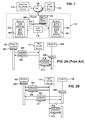
- FIG. 1 depicts a network topology illustrating cooperative NAT behavior discovery according to an embodiment of the present invention.
- a local area network (LAN) 101 may include two or more nodes, e.g., Node A 102 and Node B 104, may be connected to a router 108.
- the router 108 connects to a wide area network (WAN) 106 such as the Internet.
- WAN wide area network
- the router 108 may have a network address translator (NAT) associated with it.
- NAT network address translator
- a node may be configured to implement communication over a network using internet protocol (IP).
- IP internet protocol
- Node A 102 and Node B 104 may be IP-enabled devices or IP-enabled applications running on different devices or the same device.
- IP-enabled means that a devices makes use of IP to communicate with other hosts or devices.
- an IP-enabled device or application may include an internet protocol stack or similar network protocol stack to make use of IP to communicate with other hosts or devices.
- Node A 102 and Node B 104 may be any network capable device or network capable applications running on such devices.
- Such nodes include, but are not limited to computers, hand held internet browsers and/or email devices, Voice over Internet Protocol (VoIP) phones, video game consoles, hand held video game devices, and the like.
- VoIP Voice over Internet Protocol
- Messages may travel from one node to another over via the router 108.
- the NAT may be implemented on the router 108 in hardware, software, firmware or some combination of two or more of these.
- Node A 102, Node B 104 and the router 108 may be configured to communicate with each other according to a network protocol.
- Node A 102, and Node B 104 may be configured (either in software or hardware or some combination of both) with a network protocol stack 103 having five layers: an Application layer APP, a Transport layer TRANS, a Network layer NET (sometimes referred to as the IP layer), a Data Link Layer DLL and a Physical layer PHYS. These layers are well-known to those of skill in the art.
- the nodes 102, 104 typically implement all five layers.
- the router 108 may include a protocol stack 105 that implements only the Network layer NET, Data Link layer DLL and Physical layer PHYS. In some embodiments, one or more routers may include all five protocol stack layers.
- One example of such routers is firewalls that support "application layer gateway" which inspects application layer data.
- the illustrated configuration of the protocol stack 105 in the router 108 is relatively more common, however.
- the Application layer APP represents the level at which applications access network services. This layer represents the services that directly support applications such as software for file transfers, database access, and electronic mail. Examples of application layer software include HL7, Modbus, Session Initiation Protocol (SIP), and Simple Sensor Interface Protocol (SSI).
- SSL7 Session Initiation Protocol
- SIP Session Initiation Protocol
- SSI Simple Sensor Interface Protocol
- the Application layer APP may be implemented with software protocols such as Hypertext Transfer Protocol (HTTP), Session Initiation Protocol (SIP), Simple Mail Transfer Protocol (SMTP), Short Message Peer-to-Peer Protocol (SMPP), Simple Network Management Protocol (SNMP), File Transfer Protocol (FTP), Teletype Network (TELNET), Network File System (NFS), Network Time Protocol (NTP), Real-time Transport Protocol (RTP), Dynamic Host Configuration Protocol (DHCP), and Domain Name System (DNS).
- HTTP Hypertext Transfer Protocol
- SIP Session Initiation Protocol
- SMTP Simple Mail Transfer Protocol
- SMPP Short Message Peer-to-Peer Protocol
- SNMP Simple Network Management Protocol
- FTP File Transfer Protocol
- TELNET Teletype Network
- NFS Network File System
- NTP Network Time Protocol
- RTP Real-time Transport Protocol
- DHCP Dynamic Host Configuration Protocol
- DNS Domain Name System
- the Presentation layer may also manages security issues by providing services such as data encryption, and compresses data so that fewer bits need to be transferred on the network.
- the Session layer allows two applications on different computers to establish, use, and end a session.
- the Session layer may establish dialog control between the two computers in a session, regulating which side transmits, plus when and how long it transmits.
- the transport layer TRANS services requests from the Application layer APP and issues service requests to the Network layer NET.
- the Transport layer TRANS may also handle error recognition and recovery.
- the Transport layer may also repackage long messages when necessary into small packets for transmission.
- the Transport layer rebuilds packets into the original message.
- the Transport layer for a receiving host may also send receipt acknowledgments. Examples of particular Transport layer protocols include Transmission Control Protocol (TCP), User Datagram Protocol (UDP) and Stream Control Transmission Protocol (SCTP), all of which, and equivalents thereof, are well-known to those of skill in the art.
- TCP Transmission Control Protocol
- UDP User Datagram Protocol
- SCTP Stream Control Transmission Protocol
- the Transport layer TRANS is the layer that typically supports packet fragmentation.
- fragmentation may take place in the Transport layer of the host originating a message or at the Transport layer of any of the routers along the path between that host and the message's intended recipient. Not all transport layer implementations necessarily handle error recognition and recovery. TCP, for example, does handle error recognition and recovery, but UDP does not.
- the Network layer NET addresses messages and translates logical addresses and names into physical addresses. It also determines the route from the source to the destination computer.
- the Network layer may also manages traffic problems, such as switching, routing, and controlling the congestion of data packets. Examples of particular Network layer protocols include, but are not limited to, Internet Protocol (IP), Internet Control Message Protocol (ICMP), IP Security (Ipsec), Address Resolution Protocol (ARP), Routing Information Protocol (RIP) and Open Shortest Path First (OSPF) all of which, and equivalents thereof, are well-known to those of skill in the art
- IP Internet Protocol
- ICMP Internet Control Message Protocol
- Ipsec IP Security
- ARP Address Resolution Protocol
- RIP Routing Information Protocol
- OSPF Open Shortest Path First
- the Data Link layer DLL packages raw bits from the Physical layer PHYS into frames (logical, structured packets for data).
- the Data Link layer may also be responsible for transferring frames from one computer to another, without errors. After sending a frame, the Data Link layer DLL waits for an acknowledgment from the receiving computer.
- Examples of particular Data Link layer protocols include, but are not limited to, Point-to-Point Protocol (PPP), Serial Line Internet Protocol (SLIP) and Media Access Control (MAC) all of which, and equivalents thereof, are well-known to those of skill in the art.
- PPP Point-to-Point Protocol
- SLIP Serial Line Internet Protocol
- MAC Media Access Control
- the Data Link layer DLL typically limits the MTU size.
- the Physical layer PHYS transmits bits from one computer to another and regulates the transmission of a stream of bits over a physical medium.
- This layer defines how the cable is attached to the network adapter and what transmission technique is used to send data over the cable.
- Examples of particular Physical layer protocols and standards include, but are not limited to, RS-232, V.35, V.34, I.430, I.431, T1, El, 10BASE-T, 100BASE-TX, POTS, SONET, DSL, 802.11a, 802.11b, 802.11g, 802.11n all of which, and equivalents thereof, are well-known to those of skill in the art
- a message originating at Node A 102 starts at the Application layer APP and works its way down the protocol stack to the Physical layer PHYS.
- the message arrives as Host 2 104, it is received at the Physical layer PHYS and works its way up the stack to the Application layer APP.
- the message may be received at the Physical layer PHYS of router 108 and work its way up to the Transport layer TRANS and then back down the stack to the Physical layer PHYS for transmission to router 108.
- the process may be repeated for any additional routers (not shown) along the path between Node A 102 and Node B 104.
- peer-to-peer situations once a connection has been established between the Node A 102 and Node B 104 they may communicate directly by peer-to-peer connections, e.g., at the Application layer APP or at the Transport layer TRANS.
- the router 108 may include a network address translator. However, this is not necessary for all embodiments of the invention. If the router 108 includes a NAT, Node A 102 and Node B 104 may have to traverse the NAT in order to establish peer-to-peer connections with each other, with other node connected in the LAN 101 or with other nodes connected to the WAN 106. To facilitate NAT traversal, Node A 102 and Node B 104 may obtain and share information 110 regarding the NAT. There are a number of ways in which the information 110 may be obtained and shared. By way of example, and without loss of generality, Node A 102 and Node B 104 may obtain the information 110 through individual attempts at NAT traversal. Such attempts at NAT traversal may involve the use of a STUN server 112. Alternatively, Node A 102 and Node B 104 may obtain the information 110 from other Nodes connected to the LAN 101.
- the information 110 may be shared in any of a number of different ways.
- Node A 102 and Node B 104 may store the information locally, e.g., in a cache or other memory location.
- storing information locally may include, among other things, storing the information in particular memory locations at each corresponding device.
- Node A and Node B are different applications on the same device, storing the information locally may include, among other things, storing the information in particular memory locations associated with the device. If the information 110 is stored locally, Node A and Node B may query each other directly prior to their respective attempts at NAT traversal to obtain the information 110.
- the information 110 may be stored in a memory location that is commonly accessible to both Node A 102 and Node B 104. Such a commonly accessible memory location may be on another node or device connected to the LAN 101 or the WAN 106. By way of example, the commonly accessible memory location may be a common database server 114 connected to the WAN 106. In some embodiments, the information 110 may be obtained by and stored at the router 108. This may require special implementation at the router 108.
- the information 110 may include a unique address for the router, e.g., a globally unique address such as a Media Access Control (MAC) address or internal IP address.
- a MAC address also known as a hardware address or adapter address is a quasi-unique identifier attached to most network adapters.
- a MAC address is typically a number that acts like a name for a particular network adapter.
- network cards or built-in network adapters in two different computers could have different names, or MAC addresses, as could an Ethernet adapter and a wireless adapter in the same computer, and as could multiple network cards in a router.
- the MAC address may be assigned according to a suitable protocol such as MAC-48, EUI-48, and EUI-64, which are designed to be globally unique.
- the information 110 may include information regarding the type of NAT behavior, if any, exhibited by the router 108, and/or whether any ports on the router are being used by devices connected to the LAN 101.
- Examples of other NAT behavior information that may be shared includes, but is not limited to (i) the number of active sessions via the NAT; or (ii) the collective traffic load on the NAT.
- the information 110 may include a value of a flag realizing atomicity of port prediction against symmetric NAT.
- the flag may indicate whether a particular atomic for port prediction is locked or unlocked.
- An atomic lock is sometimes used for port prediction in symmetric NAT traversal. The locking is useful since port prediction may fail if other nodes under the same NAT create another NAT binding during the prediction phase.
- Node A 102 and Node B 104 may implement NAT discovery by any conventional technique, which may be implemented in hardware, software, firmware or some combination of two or more of these.
- FIG. 2A depicts one type of NAT discovery.
- Node A 102 may, at a startup 202, send a request 204 for NAT information to the STUN server 112, which may send back a response 206.
- the response 206 may include information regarding the type of NAT that Node A 102 is behind.
- Node B 104 at a startup 208, may similarly send a request 210 and receive response 212.
- the responses 206, 212 may each include the same or similar information regarding the NAT behavior, particularly if both Node A 102 and Node B 104 are behind the same NAT. However, depending on the nature of the NAT in the router 108, the NAT behavior may change over time. Embodiments of the invention allow sharing of NAT behavior information which can facilitate NAT traversal.
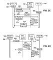
- Node A 102 and Node B 104 may share NAT information 110 as follows.
- Node A 102 may, at a startup 202, send a request 204 for NAT information to the STUN server 112, which may send back a response 206.
- the response 206 may include information 110 regarding the type of NAT that Node A 102 is behind.
- the information 110 may be stored locally at Node A 102.
- Node B 104 at a startup 208, may send a request 209 to one or more other nodes behind the router 108.
- Node B 104 may send the request 209 to Node A 102.
- the request 209 may be broadcast to all other nodes behind the router 108 since Node B 104 may not know which of them may have information regarding the NAT behavior of the router. Any of the nodes that receive the request 209 may respond with NAT behavior information. In this example, Node A 102 had previously obtained information 110. Therefore, Node A 102 may send a response 211 to Node B 104 containing the information 110 or some useful subset of that information. If none of the other nodes responds to the request 209, Node B 104 may fall back to conventional NAT discovery, e.g., by sending a request 210 to the STUN server 212 and receiving a response 212. Information obtained from the response may be stored locally and made available to other nodes upon request.
- Node A 102 may, at a startup 202, send the STUN server 112 a request 204 for NAT information.
- the STUN server 112 may send back a response 206 containing NAT behavior information 110, which may then be stored locally at Node A 102.
- the NAT behavior information 110 may be incomplete, e.g., it may narrow the NAT behavior to being of more than one possible type.
- Node B 104 at a startup 208, may send a request 209 to one or more other nodes behind the router 108 including Node A 102.
- Node A 102 may send a partial response 213.
- the partial response 213 may include the information Node A 102 was able to obtain.
- the partial response 213 may also indicate what additional information is needed to characterized the NAT behavior of the router 108.
- Node B 104 may then send a request 210 to the STUN server 112 and receive a response 212 in return.
- the response 212 may provide the missing information needed to characterize the NAT behavior of the router 108.
- Node B 104 may then share this information, e.g., by sending an update response 214 to Node A 102 and/or any other nodes behind the router 108.
- the process of partial response and update response pairs may continue until details of NAT behavior are fully determined. This may be particularly useful in cases where the router 108 allocates external bindings for multiple requests with non-deterministic behavior.
- requests to and responses from the STUN server 112 may be subject to latencies associated with both the LAN 101 and the WAN 106. Requests from one node to another on the LAN 101 are typically subject only to latencies associated with the LAN 101.
- WAN latencies are generally much larger than LAN latencies. For example, with a theoretical WAN latencies of about 100 milliseconds and LAN latencies of less than about 1 millisecond, sharing NAT behavior information 110 among the nodes on the LAN 101 could improve the NAT behavior determination phase by a factor of over 100.
- nodes on the LAN 101 may cooperatively share NAT information after each node has independently determined NAT behavior type on its own.
- gossip between nodes about determined behavior could identify a router that has bad local port preservation behavior, which could effectively turn the router 108 from port-restricted to symmetric behavior.
- Sharing of the information 110 may be used to diagnose changes to the behavior of the router 108. Sharing of the information 110 may also be used to a priori workaround NAT issues associated with bad local port preservation. For instance, multiple nodes behind the router 108 could broadcast to each other which local ports on the router 108 they want to use.
- a given node could change the selected port if another node (e.g., Node B 104) is already using the selected port.
- nodes may gossip about other unanticipated behavior changes of the local network environment of the LAN 101.
- a residential NAT typically has one global IP address that is dynamically assigned by ISP (Internet Service Provider such as Comcast) using a protocol called DHCP.
- ISP Internet Service Provider such as Comcast
- DHCP Internet Service Provider
- the assigned dynamic IP for NAT may expire and the ISP could assign another IP address. If that happens, it may take some time for a local node to detect such event. If one node detects the event, it may notify other nodes, using broadcast, of the event.
- the NAT-related information 110 was stored locally at each node behind the router 108.
- the information 110 may be stored at some common location that is accessible to all the nodes behind the router 108.
- a common location may be a common database server 114 or similar node connected to the WAN 106.
- the common database server 114 may be accessed using a suitable protocol, such as hypertext transfer protocol (HTTP).
- HTTP hypertext transfer protocol
- the common location may be a node that is part of the LAN 101.
- the information 110 may be stored at the router 108.
- a node e.g., Node A 102 may send a NAT information request 205 to the router 108, e.g., at startup 202.
- the router 108 may be configured, e.g., through appropriate programming, to send a request 204 to the STUN server 112 and receive a response 206 in return. The router 108 may then forward a reply 215 based on the response 206 to Node A 102.
- the router 108 may optionally determine the NAT behavior information 110 from the response 206 and store the information, e.g., in a memory locally accessible by the router 108.
- the reply 215 may include NAT behavior information 110 obtained from the response 206. Alternatively, the reply 215 may involve forwarding the response 206 to Node A 102.
- the router 108 may respond directly using the stored information 110. For example, at startup 208, Node B 104 may send a NAT behavior information request 216 to the router 108. In response, the router 108 may send a reply 218 based on the stored NAT behavior information 110.
- the address of the router 108 is well-known to all nodes behind it. In such a case, the requests 205, 216 and replies 215, 218 do not need to be broadcast. Furthermore, in the example depicted in FIG. 2D , only one round trip message is sent between each node and the router 108. In conventional situations, by contrast, each node talks to the NAT STUN Server, which often requires multiple roundtrip messages. In addition, the router 108 may optionally perform behavior determination with the NAT STUN Server 112 in a lazy fashion, i.e., only when a request is made to it from a client.
- NAT behavior of the router is deterministic, this may also occur at initialization of the router 108.
- communication with the NAT STUN Server 112 may be omitted since the router behavior is well-known and may be communicated directly to the nodes behind the router 108.
- Embodiments of the present invention are different from UPnP in a number of ways. Most significantly, when a UPnP device is added to a LAN the UPnP device advertises its services to control points on the LAN. In embodiments of the present invention, by contrast, nodes on the LAN find out information about the control points (NATs on Routers) and make that information available to other devices.
- NATs on Routers information about the control points
- UPnP is mainly supported only by residential routers, but not by other larger scale routers.
- the routers in a hotel that provides Internet access services from rooms typically do not support UPnP.
- Another case in which UPnP does not work is that some ISP may provide private addresses for routers that provide certain services, e.g., HOT SPOT service.
- the external address a node obtains is a private address of the nearest UPnP NAT.
- the node still needs to use a STUN server to obtain an actual global address that is routable over the Internet.
- there many existing routers do not support UPnP, or UPnP may not be turned on for many routers that do support UPnP.
- a single application running on a device on the local network 101 could perform many, but not all of these operations on behalf of other applications.
- the device running this application is referred to herein as a NAT proxy. If a NAT proxy is only running on one device, it may not be able to determine certain NAT issues associated with bindings to different internal IP addresses. This may be overcome by running at least two instances of this application on two devices, although much of the ease of use may be lost by doing this.
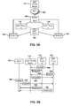
- Embodiments that utilize NAT proxies may be understood with respect to FIG. 3A and FIG. 3B .
- the local network 101 may include a first NAT proxy 116 associated with Node A 102 and a second NAT proxy 118 associated with Node B 104.
- the NAT proxies 116, 118 may be coupled to the router 108.
- the NAT proxies may query the stun server 112 from time to time in order to obtain NAT behavior information 110 and share it with Node A 102, Node B 104 and any other nodes behind the router 108.
- the first NAT proxy 116 may send a request 204 to the STUN server 112 and receive a response 206 in reply.
- the second NAT proxy 118 may send a request 224 to the STUN server 112 and receive a response 226 in reply.
- the NAT proxies 116, 118 may derive the NAT behavior information 110 in whole or in part from the responses 206, 226. After the information 110 has been derived, one of the nodes connected to the router 108 may query the NAT proxies 116, 118 for the NAT behavior information 110. For example, Node A 102 may broadcast a request 228 to the NAT proxies 116, 118, which may respectively send responses 230, 232 in reply.
- a NAT proxy application may be co-located on the same physical device node as the requesting application.
- a node only needs to receive one response from any NAT proxy. It is possible that the NAT proxies could run in a hierarchical fashion where only one proxy has the responsibility for sending responses in the local network. This has the unfortunate side-effect of creating a single point of failure within an otherwise redundant network configuration.
- the NAT proxy technique described with respect to FIG. 3A and FIG. 3B may be combined with the partial response/update response technique described above with respect to FIG. 2C to arrive at a cooperative global understanding of NAT behavior type between proxy nodes.
- each node is behind a single NAT. It is possible, in some network configurations for a node to be located behind more than one NAT. Embodiments of the present invention may be modified to address situations where a given Node lies behind more than one NAT. For example, as shown in FIG. 4 both Node A 102 and Node B 104 are behind NAT 1. However, Node B 102 is also behind NAT 2 though NAT N. In this example, NAT 1 may be part of a gateway router between the local area network 101 and the wide area network 106. Information about the presence and behavior of NAT 1 may be useful to both Node A 102 and Node B 104 for communication with the WAN 106. In addition, information about NAT1 and NAT 2 through NAT N will be useful for situations where Node A 102 and Node B 104 communicate with each other.
- the nodes 102, 104, 120 may determine how many NATs they are behind though the use of a field within the header of a datagram having a value that is reduced at each NAT device encountered en route to the datagram's destination.
- field may be a time to live (TTL) field.
- TTL time to live
- Ipv4 TTL refers to an 8-bit field in the Internet Protocol (IP) header. It is the 9th octet of 20.
- the time to live value may be thought of as an upper bound on the time that an IP datagram can exist in an internet system.
- the TTL field may be set by the sender of the datagram, and reduced by every host on the route to its destination.
- TTL field reaches zero before the datagram arrives at its destination, then the datagram is discarded and an Internet Control Message Protocol (ICMP) error datagram (11 - Time Exceeded) is sent back to the sender.
- ICMP Internet Control Message Protocol
- the TTL field is conventionally used to avoid a situation in which an undeliverable datagram keeps circulating on an internet system, and such a system eventually becoming overwhelmed by large numbers of such "immortal" datagrams.
- time to live may be measured in seconds, although every host that passes the datagram must reduce the TTL by at least one unit.
- the TTL field is reduced by one on every hop. To reflect this practice, the field is named hop limit in IPv6.
- the ICMP error datagram identifies the last host the datagram arrived at before timing out.
- a tool called traceroute uses ICMP error messages to detect a path to a remote end node.
- TTL or hop limit fields may be used to determine the addresses of the NATs between Node A 102 and Node B 104 in a manner similar to that used in a traceroute command.
- Node A 102 and Node B 104 and other nodes 120 may share information 110 relating to the behavior of NAT 1 and NAT 2 through NAT N.
- the nodes 102, 104, 120 may obtain the NAT information 110, e.g., as discussed above with respect to FIGs. 2A-2D and store the information in a manner accessible by all of the nodes on the LAN 101.
- the information 110 may be cached on a server 112 such as a common database server or STUN server.
- the server 112 may reside between the LAN 101 between the WAN 106. It is further noted that devices hosting NAT 1 and NAT 2 through NAT N may also gather information about themselves and share it with the nodes 102, 104, 120.
- a wireless network 500 may include first, second and third, wireless access points WAP1, WAP2, and WAP3, which may be at geographically distributed locations.
- the wireless access points WAP1, WAP2, and WAP3 may be implemented, e.g., by wireless routers, which may include network address translators NAT1, NAT2 and NAT3 respectively.
- the wireless access points WAP1, WAP2, and WAP3 may be characterized by corresponding coverage areas 502, 504, 505.
- a wireless node 507 may access the network 501 if it is within one of the coverage areas.
- the wireless node 507 may be any device configured for wireless network communication.
- Such devices include, but are not limited to laptop computers, portable video game devices, portable music download devices, portable Voice over Internet protocol (VoIP) devices, and portable Internet browser or email devices, such as the Blackberry®. Blackberry® is a registered trademark of Research in Motion LTD of Waterloo, Ontario Canada.
- VoIP Voice over Internet protocol
- portable Internet browser or email devices such as the Blackberry®. Blackberry® is a registered trademark of Research in Motion LTD of Waterloo, Ontario Canada.
- such devices include wireless devices that incorporate two or more functions, such as VoIP, internet, email and music downloads.
- An example of such a device is the iPhone from Apple Inc. of Cupertino, California.
- the wireless access points WAP1, WAP2, WAP3 may be connected to a wide area network 506 via a router 508.
- a router 508 In addition there may be other nodes A, B, C connected between the router 508 and the wireless access points WAP1, WAP2 and WAP3 respectively.
- Information 510 regarding the network address translators NAT1, NAT2, NAT3 may be stored at a centrally accessible cache 512 that is coupled to the router 508.
- the wireless node 507 may gather part of the information 510 through conventional NAT traversal and share it with other nodes as shown in FIG. 2B or FIG. 2C .
- the router 508 or wireless access points WAP1, WAP2, WAP3 may obtain the information 510 as described above with respect to FIG. 2D .
- the other nodes A, B, C may obtain all or part of the information by acting as proxy nodes as described above with respect to FIG. 3A and FIG. 3B .
- the information is shown as being stored in a single location 512, the information 510 may alternatively be distributed among the nodes connected to the network 501.
- information relating to the wireless network address translators NAT1, NAT2, NAT3 may be stored locally at the corresponding wireless access points WAP1, WAP2, WAP3. It is noted that the information 510 may include a geographic location for each NAT or wireless access point.
- the information 510 may also include other general information related to the NAT or wireless access point. Such information may include, but is not limited to information relating to local restaurants, weather, identity of other devices connected to the network 501 number of times a particular wireless access point has been visited and other general information. A wireless device may access this information when accessing the network 510 through any of the wireless access points WAP1, WAP2, WAP3.
- the wireless node 507 may move from one coverage area to another, e.g., from the coverage area 502 for the first wireless access point WAP1 to the coverage area 504 for the second wireless access point WAP2.
- the information 510 may be organized such that the wireless device 507 can request NAT information for a neighboring wireless access point, such as the second wireless access point WAP2.
- the device 507 may be programmed to determine, e.g., from GPS data or wireless signal strength a general direction of travel of the wireless device and use this direction to estimate which wireless access points the device is likely to encounter.
- Embodiments of the present invention may also apply to situations in which a NAT moves.
- the wireless access points WAP1, WAP2, WAP3 may be mounted on vehicles.
- the wireless node 507 may determine whether a NAT is mobile e.g., from geographical information.
- the wireless node 507 may include a geographical location system, such as a global positioning satellite system (GPSS) receiver. Using such a system, the node 507 may its own location when it encounters the NAT. If the node 507 encounters the same NAT when the node is in two different locations that are sufficiently far apart the node may infer that the NAT has moved.
- GPSS global positioning satellite system
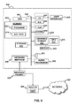
- FIG. 6 is a block diagram illustrating the components of a node 600 suitable for implementing NAT behavior discovery according to an embodiment of the present invention.
- the node 600 may be implemented as a computer system, such as a personal computer, video game console, personal digital assistant, wireless device, or other digital device, suitable for practicing an embodiment of the invention.
- the node 600 may be a router.
- the node 600 may include a central processing unit (CPU) 601 configured to run software applications and optionally an operating system.
- CPU central processing unit
- the CPU 601 may include one or more processing cores.
- the CPU 601 may be a parallel processor module, such as a Cell Processor.
- a Cell Processor An example of a Cell Processor architecture is described in detail, e.g., in Cell Broadband Engine Architecture, copyright International Business Machines Corporation, Sony Computer Entertainment Incorporated, Toshiba Corporation August 8, 2005 a copy of which may be downloaded at http://cell.scei.co.jp/, the entire contents of which are incorporated herein by reference.
- a memory 602 may be coupled to the CPU 601.
- the memory 602 may store applications and data for use by the CPU 601.
- the memory 602 may be in the form of an integrated circuit, e.g., RAM, DRAM, ROM, and the like).
- a computer program 603 may be stored in the memory 602 in the form of instructions that can be executed on the processor 601.
- the instructions of the program 603 may be configured to implement, amongst other things, NAT behavior discovery, e.g., as described above.
- the program 603 may be instructions that, when executed, cause the node 600 to determine information regarding the behavior of one or more NATs and store the information in such a way that the information is retrievable by node 600 or one or more other nodes.
- the program 603 may be configured to retrieve information regarding behavior of one or more NATs obtained by one or more other nodes and use the information to traverse one or more of the NATs.
- the memory 602 may contain data that is generated by or usable by the program 603.
- the memory 602 may contain information 610 relating to one or more NATs.
- the information 610 may include, but is not limited to (i) NAT behavior information (e.g., whether the NAT is full cone, restricted cone, port restricted, symmetric) including whether the NAT behavior includes port preservation or not; (ii) available STUN server addresses; and (iii) common database addresses.
- the information 610 may be stored in a section of the memory 602 that can be accessed by other nodes.
- the node 600 may further include a storage device 615 that provides non-volatile storage for applications and data.
- the storage device 615 may be a fixed disk drive, removable disk drive, flash memory device, tape drive, CD-ROM, DVD-ROM, Blu-ray, HD-DVD, UMD, or other optical storage devices.
- the node 600 may also include well-known support functions 620 commonly used in computing systems. Such support functions may include such features as input/output (I/O) elements 621, power supplies (P/S) 622, a clock (CLK) 623 and cache 624.
- I/O input/output
- P/S power supplies
- CLK clock
- One or more user input devices 625 may be used to communicate user inputs from one or more users to the node 600.
- one or more of the user input devices 625 may be coupled to the node 600 via the I/O elements 621.
- suitable input devices 620 include keyboards, mice, joysticks, touch pads, touch screens, light pens, still or video cameras, and/or microphones.
- the user interface devices 625 it is desirable for the user interface devices 625 to include both a camera and a microphone.
- a network interface 626 allows the node 600 to communicate with other computer systems via an electronic communications network 627.
- the network 627 may be a wide area network and the node 600 may be on a local area network.
- the node may interface with the network 627 via a router 608, which may include a network address translator NAT.
- the node 600 itself may be a router, e.g., as described above with respect to FIG. 2D .
- the network interface 626 may include wired or wireless communication over local area networks and wide area networks such as the Internet.
- the node 600 may send and receive data and/or requests for files via one or more message packets 628 over the network 627.
- the network interface 626 may include or be part of a network card, network adapter or network interface card (NIC), such as an Ethernet card.
- the network interface 626 may include computer hardware designed to allow the node 600 to communicate over the network 627.
- the network interface 626 may provides physical access to a networking medium and provide a low-level addressing system, e.g., through the use of MAC addresses. Consequently, with respect to the Internet Protocol stack, the network interface 626 may be regarded as both a physical layer device and a data link layer device.
- the node 600 may further comprise a graphics subsystem 630, which may include a graphics processing unit (GPU) 635 and graphics memory 640.
- the graphics memory 640 may include a display memory (e.g., a frame buffer) used for storing pixel data for each pixel of an output image.
- the graphics memory 640 may be integrated in the same device as the GPU 635, connected as a separate device with GPU 635, and/or implemented within the memory 602. Pixel data may be provided to the graphics memory 640 directly from the CPU 601.
- the CPU 601 may provide the GPU 635 with data and/or instructions defining the desired output images, from which the GPU 635 may generate the pixel data of one or more output images.
- the data and/or instructions defining the desired output images may be stored in memory 602 and/or graphics memory 640.
- the GPU 635 may be configured (e.g., by suitable programming or hardware configuration) with 3D rendering capabilities for generating pixel data for output images from instructions and data defining the geometry, lighting, shading, texturing, motion, and/or camera parameters for a scene.
- the GPU 635 may further include one or more programmable execution units capable of executing shader programs.
- the graphics subsystem 630 may periodically output pixel data for an image from graphics memory 640 to be displayed on a display device 650.
- the display device 650 may be any device capable of displaying visual information in response to a signal from the computer system 600, including CRT, LCD, plasma, and OLED displays.
- the node 600 may provide the display device 650 with an analog or digital signal.
- the display 650 may include a cathode ray tube (CRT) or flat panel screen that displays text, numerals, graphical symbols, or images.
- the node 600 may include one or more audio speakers 652 that produce audible or otherwise detectable sounds.
- the node 600 may further include an audio processor 655 adapted to generate analog or digital audio output from instructions and/or data provided by the CPU 601, memory 602, and/or storage 615.
- an audio processor 655 adapted to generate analog or digital audio output from instructions and/or data provided by the CPU 601, memory 602, and/or storage 615.
- the node 600 it is sometimes desirable for the node 600 to include a graphical display device 650 and an audio speaker 652.
- the components of the node 600 including the CPU 601, memory 602, support functions 620, data storage 615, user input devices 625, network interface 626, graphics subsystem 630 speaker 652 and audio processor 655 may be operably connected to each other via one or more data buses 660. These components may be implemented in hardware, software, firmware or some combination of two or more of these.
- Embodiments of the present invention may solve a key issue in networking deployments related to NAT devices [routers that perform network address translation]. It is possible that a router with a fully specified behavior may be used to implement NAT behavior information discovery and distribution in a centralized way. It is possible that some of the functionality may be lost if the state of individual applications cannot be fully gleaned at such a router. However, additions to this mechanism may account for this deficiency, though perhaps with some associated overhead.
- peer network nodes that are behind a common NAT may cooperate to cooperate to better solve the NAT traversal problem in a decentralized way.
Claims (15)
- Verfahren zum Fördern der Traversierung eines Netzadressenumsetzers, NAT, in einem Knoten (102), der dafür ausgelegt ist, mit einem oder mehreren anderen Knoten (104) über ein Netz zu kommunizieren, wobei das Verfahren Folgendes umfasst:a) Bestimmen von Informationen bezüglich des Verhaltens eines oder mehrerer NATs bei dem Knoten; und Speichern der Informationen in einer derartigen Weise, dass die Informationen durch einen oder mehrere andere Knoten abrufbar sind; oderb) Abrufen von Informationen bezüglich des Verhaltens eines oder mehrerer NATs, die durch einen oder mehrere andere Knoten erhalten worden sind, und Verwenden der Informationen, um einen oder mehrere der NATs zu durchqueren; oderc) sowohl a) als auch b).
- Verfahren nach Anspruch 1, wobei das Bestimmen der Informationen bezüglich des Verhaltens des eines oder der mehreren NATs das Bestimmen einer Medienzugriffssteuer-Adresse, MAC-Adresse, für einen oder mehrere der NATs enthält.
- Verfahren nach Anspruch 1, wobei das Bestimmen der Informationen bezüglich des Verhaltens des eines oder der mehreren NATs das Bestimmen enthält, wie viele NATs es zwischen einer gegebenen externen IP-Adresse und einem der anderen Knoten gibt.
- Verfahren nach Anspruch 3, wobei das Bestimmen, wie viele NATs es zwischen einer gegebenen externen IP-Adresse und einem der anderen Knoten gibt, das Senden eines Datagramms mit einer vorgegebenen Lebensdauer und, falls in Reaktion auf das Datagramm ein Zeitüberschreitungsfehler zu dem Knoten zurückgeschickt wird, das erneute Senden des Datagramms mit einer inkrementieren Lebensdauer enthält.
- Verfahren nach Anspruch 1, wobei die Informationen bezüglich des Verhaltens eines oder mehrerer NATs einen NAT-Typ enthalten.
- Verfahren nach Anspruch 1, wobei die Informationen bezüglich des Verhaltens eines oder mehrerer NATs geographische Informationen bezüglich des NAT enthalten.
- Verfahren nach Anspruch 1, wobei das Speichern der Informationen das Verteilen der Informationen über ein Peer-zu-Peer-Netz enthält.
- Verfahren nach Anspruch 1, wobei das Speichern der Informationen in einer derartigen Weise, dass die Informationen durch einen oder mehrere andere Knoten abrufbar sind, das Speichern der Informationen in einem Server enthält, der für den Knoten und die anderen Knoten zugänglich ist, wobei der Server ein gemeinsamer Datenbank-Server ist.
- Verfahren nach Anspruch 1, wobei b) das Abrufen von Informationen bezüglich des Verhaltens eines oder mehrerer NATs von einem zentralen Ort enthält, der durch den Knoten und den einen oder die mehreren anderen Knoten zugänglich ist.
- Verfahren nach Anspruch 1, wobei sich der Knoten und der eine oder die mehreren anderen Knoten hinter demselben NAT befinden.
- Verfahren nach Anspruch 1, wobei der Knoten ein Router ist, der durch den einen oder die mehreren anderen Knoten zugänglich ist.
- Verfahren nach Anspruch 11, wobei das Speichern der Informationen in einer derartigen Weise, dass die Informationen durch einen oder mehrere andere Knoten abrufbar sind, das Speichern der Informationen in einem Cache in dem Router enthält.
- Verfahren nach Anspruch 1, wobei die Informationen bezüglich des Verhaltens eines oder mehrerer NATs NAT-Verhaltensinformationen, eine oder mehrere Adressen verfügbarer STUN-Server, eine oder mehrere Adressen gemeinsamer Datenbanken, eine Anzahl der aktiven Sitzungen über einen NAT, eine gemeinsame Verkehrslast in einem NAT oder einen Wert eines Merkers, der die Atomizität der Port-Vorhersage gegen einen symmetrischen NAT erkennen lässt, enthalten.
- Vorrichtung zum Fördern der Traversierung eines Netzadressenumsetzers, NAT, die Folgendes umfasst:einen Knoten (102), der dafür ausgelegt ist, mit einem oder mehreren anderen Knoten (104) über ein Netz zu kommunizieren; undeinen Satz ausführbarer Anweisungen, die, wenn sie in dem Knoten ausgeführt werden, den Knoten veranlassen,a) Informationen bezüglich des Verhaltens eines oder mehrerer NATs bei dem Knoten zu bestimmen; und die Informationen in einer derartigen Weise zu speichern, dass die Informationen durch einen oder mehrere andere Knoten abrufbar sind; oderb) Informationen bezüglich des Verhaltens eines oder mehrerer NATs, die durch einen oder mehrere andere Knoten erhalten worden sind, abzurufen und die Informationen zu verwenden, um einen oder mehrere der NATs zu durchqueren; oderc) sowohl a) als auch b).
- Vorrichtung nach Anspruch 14, wobei die Informationen bezüglich des Verhaltens eines oder mehrerer NATs NAT-Verhaltensinformationen, eine oder mehrere Adressen verfügbarer STUN-Server, eine oder mehrere Adressen gemeinsamer Datenbanken, eine Anzahl der aktiven Sitzungen über einen NAT, eine gemeinsame Verkehrslast in einem NAT oder einen Wert eines Merkers, der die Atomizität der Port-Vorhersage gegen einen symmetrischen NAT erkennen lässt, enthalten.
Priority Applications (1)
| Application Number | Priority Date | Filing Date | Title |
|---|---|---|---|
| EP15152064.0A EP2890092B1 (de) | 2007-07-27 | 2008-07-21 | Kooperative nat-verhaltensentdeckung |
Applications Claiming Priority (2)
| Application Number | Priority Date | Filing Date | Title |
|---|---|---|---|
| US11/829,831 US7933273B2 (en) | 2007-07-27 | 2007-07-27 | Cooperative NAT behavior discovery |
| PCT/US2008/070661 WO2009018004A1 (en) | 2007-07-27 | 2008-07-21 | Cooperative nat behavior discovery |
Related Child Applications (2)
| Application Number | Title | Priority Date | Filing Date |
|---|---|---|---|
| EP15152064.0A Division-Into EP2890092B1 (de) | 2007-07-27 | 2008-07-21 | Kooperative nat-verhaltensentdeckung |
| EP15152064.0A Division EP2890092B1 (de) | 2007-07-27 | 2008-07-21 | Kooperative nat-verhaltensentdeckung |
Publications (3)
| Publication Number | Publication Date |
|---|---|
| EP2171933A1 EP2171933A1 (de) | 2010-04-07 |
| EP2171933A4 EP2171933A4 (de) | 2013-09-18 |
| EP2171933B1 true EP2171933B1 (de) | 2015-04-08 |
Family
ID=40295290
Family Applications (2)
| Application Number | Title | Priority Date | Filing Date |
|---|---|---|---|
| EP15152064.0A Active EP2890092B1 (de) | 2007-07-27 | 2008-07-21 | Kooperative nat-verhaltensentdeckung |
| EP08782141.9A Active EP2171933B1 (de) | 2007-07-27 | 2008-07-21 | Kooperative NAT-Verhaltensentdeckung |
Family Applications Before (1)
| Application Number | Title | Priority Date | Filing Date |
|---|---|---|---|
| EP15152064.0A Active EP2890092B1 (de) | 2007-07-27 | 2008-07-21 | Kooperative nat-verhaltensentdeckung |
Country Status (5)
| Country | Link |
|---|---|
| US (3) | US7933273B2 (de) |
| EP (2) | EP2890092B1 (de) |
| JP (1) | JP5006968B2 (de) |
| CN (3) | CN107257389B (de) |
| WO (1) | WO2009018004A1 (de) |
Families Citing this family (39)
| Publication number | Priority date | Publication date | Assignee | Title |
|---|---|---|---|---|
| US20080298237A1 (en) * | 2006-08-03 | 2008-12-04 | Latitude Broadband, Inc. | Methods, Systems, and Apparatus of Providing QoS and Scalability in the Deployment of Real-Time Traffic Services in Packet-based Networks |
| CN101335681B (zh) * | 2007-06-27 | 2011-08-10 | 华为技术有限公司 | 获取穿越资源的方法、对等网络节点和对等网络 |
| US8631155B2 (en) * | 2007-06-29 | 2014-01-14 | Microsoft Corporation | Network address translation traversals for peer-to-peer networks |
| US7933273B2 (en) * | 2007-07-27 | 2011-04-26 | Sony Computer Entertainment Inc. | Cooperative NAT behavior discovery |
| KR101606142B1 (ko) * | 2008-11-28 | 2016-03-25 | 삼성전자주식회사 | 음성패킷망에서 네트워크 주소 번역 통과를 지원하기 위한 장치 및 방법 |
| US9160794B2 (en) * | 2008-12-04 | 2015-10-13 | Microsoft Technology Licensing, Llc | Network address translators (NAT) type detection techniques |
| US7962627B2 (en) * | 2008-12-04 | 2011-06-14 | Microsoft Corporation | Peer-to-peer network address translator (NAT) traversal techniques |
| US8280376B2 (en) * | 2008-12-31 | 2012-10-02 | Airvana, Corp. | Geography aware peer-to-peer overlay creation |
| CN101820382B (zh) * | 2009-02-28 | 2013-02-27 | 华为技术有限公司 | 一种通告网络地址转换设备信息的方法、装置和系统 |
| JP5273002B2 (ja) * | 2009-09-30 | 2013-08-28 | ブラザー工業株式会社 | 通信システム、通信制御装置、通信制御方法、及び通信制御プログラム |
| US8699378B2 (en) * | 2009-09-30 | 2014-04-15 | At&T Intellectual Property I, L.P. | Methods and apparatus for discovering hosts on an IPv6 network |
| JP5273001B2 (ja) * | 2009-09-30 | 2013-08-28 | ブラザー工業株式会社 | 通信システム、端末装置、通信方法、及び通信プログラム |
| US8412833B2 (en) | 2010-04-07 | 2013-04-02 | Apple Inc. | Apparatus and method for inviting users to online sessions |
| FR2968496B1 (fr) * | 2010-12-03 | 2013-07-05 | Sagemcom Documents Sas | Procede et dispositif pour l'appairage d'un terminal et d'un compte utilisateur |
| CN102801603B (zh) * | 2011-05-27 | 2017-04-05 | 中兴通讯股份有限公司 | 一种网络地址翻译加速的分流控制方法及装置 |
| US8838735B2 (en) * | 2011-06-28 | 2014-09-16 | At&T Intellectual Property I, L.P. | Methods, systems, and products for address translation in residential networks |
| KR20130052240A (ko) * | 2011-11-11 | 2013-05-22 | 삼성전자주식회사 | 네트워크 주소 변환기 통과 기법을 프로비저닝하기 위한 방법 및 장치 |
| CN104115473B (zh) | 2011-12-14 | 2018-05-25 | 皇家Kpn公司 | 网络网关及其测试方法 |
| EP2792131A1 (de) * | 2011-12-14 | 2014-10-22 | Koninklijke KPN N.V. | Verfahren und systeme zur ermöglichung von nat-durchdringung |
| WO2013087747A1 (en) | 2011-12-14 | 2013-06-20 | Koninklijke Kpn N.V. | Methods and systems for enabling nat traversal |
| US20150098471A1 (en) * | 2011-12-14 | 2015-04-09 | Koninklijke Kpn N.V. | Methods and Systems for Enabling NAT Traversal |
| EP2792128A1 (de) | 2011-12-14 | 2014-10-22 | Koninklijke KPN N.V. | Verbesserte serverkommunikation |
| WO2013087779A1 (en) | 2011-12-14 | 2013-06-20 | Koninklijke Kpn N.V. | Improved node in a network |
| KR101758681B1 (ko) * | 2012-03-27 | 2017-07-14 | 한화테크윈 주식회사 | 통신 시스템 및 통신 시스템에서의 데이터 송수신 방법 |
| CN102647483B (zh) * | 2012-03-31 | 2018-02-27 | 中兴通讯股份有限公司 | 获取nat类型的方法、p2p端点实体和nat实体 |
| KR101367180B1 (ko) * | 2012-05-21 | 2014-02-26 | 주식회사 바른기술 | 네트워크 서비스를 전환 및 공유하는 장치와 그 방법 |
| US9313246B2 (en) * | 2012-06-29 | 2016-04-12 | Cisco Technology, Inc. | Resilient video encoding control via explicit network indication |
| CN103414797B (zh) * | 2013-07-31 | 2016-08-24 | 中国联合网络通信集团有限公司 | Nat穿越服务器的端口分配方法和装置 |
| US9379952B2 (en) * | 2013-08-20 | 2016-06-28 | Futurewei Technologies, Inc. | Monitoring NAT behaviors through URI dereferences in web browsers |
| KR102287510B1 (ko) * | 2014-04-10 | 2021-08-06 | 엘지전자 주식회사 | 서버, 영상제공장치, 및 이를 포함하는 영상 제공 시스템 |
| TWI558149B (zh) * | 2015-06-23 | 2016-11-11 | 晶睿通訊股份有限公司 | 用於多層網路位址轉譯器結構之網路傳輸方法及網路傳輸系統 |
| CN104994184A (zh) * | 2015-06-25 | 2015-10-21 | 北京广密华安科技有限公司 | 一种nat穿透方法和装置 |
| US9860157B2 (en) | 2015-09-09 | 2018-01-02 | Sling Media Pvt Ltd | Zero configuration approach for port forwarding cascaded routers |
| CN105516342B (zh) * | 2015-12-30 | 2019-02-22 | 深圳市有信网络技术有限公司 | 一种p2p穿透同步方法及系统 |
| US10255222B2 (en) | 2016-11-22 | 2019-04-09 | Dover Electronics LLC | System and method for wirelessly transmitting data from a host digital device to an external digital location |
| CN109698869B (zh) * | 2017-10-23 | 2022-02-25 | 中国移动通信有限公司研究院 | 私网穿越方法、通信节点及存储介质 |
| US10778723B2 (en) * | 2018-03-26 | 2020-09-15 | Forescout Technologies, Inc. | Device visibility and scanning including network segments |
| JP7188046B2 (ja) * | 2018-12-14 | 2022-12-13 | 富士フイルムビジネスイノベーション株式会社 | 通信システム、通信装置、通信システムプログラム及び通信プログラム |
| US20210019285A1 (en) * | 2019-07-16 | 2021-01-21 | Citrix Systems, Inc. | File download using deduplication techniques |
Family Cites Families (89)
| Publication number | Priority date | Publication date | Assignee | Title |
|---|---|---|---|---|
| US5636216A (en) | 1994-04-08 | 1997-06-03 | Metricom, Inc. | Method for translating internet protocol addresses to other distributed network addressing schemes |
| US5488608A (en) * | 1994-04-14 | 1996-01-30 | Metricom, Inc. | Method and system for routing packets in a packet communication network using locally constructed routing tables |
| EP0774186A4 (de) | 1994-05-05 | 2005-07-20 | Catapult Entertainment Inc | Netzwerkarchitektur für echtzeit-videospiele |
| US5793763A (en) | 1995-11-03 | 1998-08-11 | Cisco Technology, Inc. | Security system for network address translation systems |
| JPH11122301A (ja) | 1997-10-20 | 1999-04-30 | Fujitsu Ltd | アドレス変換接続装置 |
| US6151601A (en) | 1997-11-12 | 2000-11-21 | Ncr Corporation | Computer architecture and method for collecting, analyzing and/or transforming internet and/or electronic commerce data for storage into a data storage area |
| US6128624A (en) | 1997-11-12 | 2000-10-03 | Ncr Corporation | Collection and integration of internet and electronic commerce data in a database during web browsing |
| US6151584A (en) | 1997-11-20 | 2000-11-21 | Ncr Corporation | Computer architecture and method for validating and collecting and metadata and data about the internet and electronic commerce environments (data discoverer) |
| FI105753B (fi) | 1997-12-31 | 2000-09-29 | Ssh Comm Security Oy | Pakettien autentisointimenetelmä verkko-osoitemuutosten ja protokollamuunnosten läsnäollessa |
| SE513828C2 (sv) | 1998-07-02 | 2000-11-13 | Effnet Group Ab | Brandväggsapparat och metod för att kontrollera nätverksdatapakettrafik mellan interna och externa nätverk |
| US6208649B1 (en) | 1998-03-11 | 2001-03-27 | Cisco Technology, Inc. | Derived VLAN mapping technique |
| US6289358B1 (en) | 1998-04-15 | 2001-09-11 | Inktomi Corporation | Delivering alternate versions of objects from an object cache |
| US6292880B1 (en) | 1998-04-15 | 2001-09-18 | Inktomi Corporation | Alias-free content-indexed object cache |
| US6128627A (en) | 1998-04-15 | 2000-10-03 | Inktomi Corporation | Consistent data storage in an object cache |
| US6128623A (en) | 1998-04-15 | 2000-10-03 | Inktomi Corporation | High performance object cache |
| US6209003B1 (en) | 1998-04-15 | 2001-03-27 | Inktomi Corporation | Garbage collection in an object cache |
| US6058431A (en) | 1998-04-23 | 2000-05-02 | Lucent Technologies Remote Access Business Unit | System and method for network address translation as an external service in the access server of a service provider |
| US6260120B1 (en) | 1998-06-29 | 2001-07-10 | Emc Corporation | Storage mapping and partitioning among multiple host processors in the presence of login state changes and host controller replacement |
| US6212565B1 (en) | 1998-08-26 | 2001-04-03 | Sun Microsystems, Inc. | Apparatus and method for improving performance of proxy server arrays that use persistent connections |
| US6138156A (en) | 1998-10-05 | 2000-10-24 | International Business Machines Corporation | Selecting and applying content-reducing filters based on dynamic environmental factors |
| US6389462B1 (en) | 1998-12-16 | 2002-05-14 | Lucent Technologies Inc. | Method and apparatus for transparently directing requests for web objects to proxy caches |
| US6333931B1 (en) | 1998-12-28 | 2001-12-25 | Cisco Technology, Inc. | Method and apparatus for interconnecting a circuit-switched telephony network and a packet-switched data network, and applications thereof |
| US6535511B1 (en) | 1999-01-07 | 2003-03-18 | Cisco Technology, Inc. | Method and system for identifying embedded addressing information in a packet for translation between disparate addressing systems |
| US6636898B1 (en) | 1999-01-29 | 2003-10-21 | International Business Machines Corporation | System and method for central management of connections in a virtual private network |
| US6393488B1 (en) | 1999-05-27 | 2002-05-21 | 3Com Corporation | System and method for supporting internet protocol subnets with network address translators |
| US6581108B1 (en) | 1999-11-30 | 2003-06-17 | Lucent Technologies Inc. | Managing multiple private data networks using network and payload address translation |
| US7917628B2 (en) | 1999-12-02 | 2011-03-29 | Western Digital Technologies, Inc. | Managed peer-to-peer applications, systems and methods for distributed data access and storage |
| US6779035B1 (en) | 2000-03-06 | 2004-08-17 | Microsoft Corporation | Application programming interface and generalized network address translator for translation of transport-layer sessions |
| US6353891B1 (en) | 2000-03-20 | 2002-03-05 | 3Com Corporation | Control channel security for realm specific internet protocol |
| US6789126B1 (en) | 2000-05-09 | 2004-09-07 | Sun Microsystems, Inc. | Addressing message gates in a distributed computing environment |
| US6618757B1 (en) | 2000-05-17 | 2003-09-09 | Nortel Networks Limited | System and method for dynamic IP address management |
| WO2001097485A2 (en) | 2000-06-14 | 2001-12-20 | At & T Wireless Services, Inc. | Method for providing transparent public addressed networks within private networks |
| WO2002003217A1 (en) | 2000-06-30 | 2002-01-10 | Net2Phone | System, method, and computer program product for resolving addressing in a network including a network address translator |
| US6661799B1 (en) | 2000-09-13 | 2003-12-09 | Alcatel Usa Sourcing, L.P. | Method and apparatus for facilitating peer-to-peer application communication |
| US20020075844A1 (en) | 2000-12-15 | 2002-06-20 | Hagen W. Alexander | Integrating public and private network resources for optimized broadband wireless access and method |
| US7155518B2 (en) | 2001-01-08 | 2006-12-26 | Interactive People Unplugged Ab | Extranet workgroup formation across multiple mobile virtual private networks |
| WO2002057917A2 (en) | 2001-01-22 | 2002-07-25 | Sun Microsystems, Inc. | Peer-to-peer network computing platform |
| US6993012B2 (en) * | 2001-02-20 | 2006-01-31 | Innomedia Pte, Ltd | Method for communicating audio data in a packet switched network |
| JP3963690B2 (ja) | 2001-03-27 | 2007-08-22 | 富士通株式会社 | パケット中継処理装置 |
| US20030009561A1 (en) | 2001-06-14 | 2003-01-09 | Sollee Patrick N. | Providing telephony services to terminals behind a firewall and /or network address translator |
| US8065394B2 (en) | 2001-08-20 | 2011-11-22 | Bally Gaming, Inc. | Local game-area network method |
| US20030051052A1 (en) | 2001-09-13 | 2003-03-13 | Koninklijke Philips Electronics N.V. | Addressing scheme for wireless mobile clients |
| US20030055978A1 (en) | 2001-09-18 | 2003-03-20 | Microsoft Corporation | Methods and systems for enabling outside-initiated traffic flows through a network address translator |
| US7254709B1 (en) | 2001-10-23 | 2007-08-07 | Avanza Technologies, Inc. | Managed information transmission of electronic items in a network environment |
| SE522998C2 (sv) | 2001-12-14 | 2004-03-23 | Hotsip Ab | Förfarande, gateway och datorprogramprodukt för att sända ett snabbmeddelande mellan två användare |
| US7058718B2 (en) | 2002-01-15 | 2006-06-06 | International Business Machines Corporation | Blended SYN cookies |
| US7133368B2 (en) | 2002-02-01 | 2006-11-07 | Microsoft Corporation | Peer-to-peer method of quality of service (QoS) probing and analysis and infrastructure employing same |
| US7676579B2 (en) | 2002-05-13 | 2010-03-09 | Sony Computer Entertainment America Inc. | Peer to peer network communication |
| US9497168B2 (en) | 2002-07-30 | 2016-11-15 | Avaya Inc. | Method and apparatus for supporting communications between a computing device within a network and an external computing device |
| US8060626B2 (en) * | 2008-09-22 | 2011-11-15 | Sony Computer Entertainment America Llc. | Method for host selection based on discovered NAT type |
| US8224985B2 (en) * | 2005-10-04 | 2012-07-17 | Sony Computer Entertainment Inc. | Peer-to-peer communication traversing symmetric network address translators |
| US7016942B1 (en) | 2002-08-05 | 2006-03-21 | Gary Odom | Dynamic hosting |
| US7302496B1 (en) * | 2002-11-12 | 2007-11-27 | Cisco Technology, Inc. | Arrangement for discovering a localized IP address realm between two endpoints |
| US7216359B2 (en) | 2002-12-19 | 2007-05-08 | International Business Machines Corporation | Secure communication overlay using IP address hopping |
| WO2004063843A2 (en) | 2003-01-15 | 2004-07-29 | Matsushita Electric Industrial Co., Ltd. | PEER-TO-PEER (P2P) CONNECTION DESPITE NETWORK ADDRESS TRANSLATOR (NATs) AT BOTH ENDS |
| US7899932B2 (en) | 2003-01-15 | 2011-03-01 | Panasonic Corporation | Relayed network address translator (NAT) traversal |
| IL156924A (en) * | 2003-07-15 | 2009-05-04 | Tadiran Telecom Ltd | Communication between users located behind nat device |
| US8234383B2 (en) | 2003-11-07 | 2012-07-31 | Panasonic Corporation | Bubble packet port identification using detection packets |
| DE10353925B4 (de) | 2003-11-18 | 2009-12-24 | Nec Europe Ltd. | Verfahren zum Austausch von Daten zwischen zwei Hosts |
| JP4426262B2 (ja) | 2003-11-26 | 2010-03-03 | 株式会社日立製作所 | ディスクアレイ装置及びディスクアレイ装置の障害回避方法 |
| CN100399768C (zh) * | 2003-12-24 | 2008-07-02 | 华为技术有限公司 | 实现网络地址转换穿越的方法、系统 |
| JP2007528677A (ja) | 2004-03-09 | 2007-10-11 | クリーク コミュニケーションズ エルエルシー | シンメトリック・ファイアウォールの背後のクライアントのピアツーピア接続のためのシステムおよび方法 |
| US20050201391A1 (en) * | 2004-03-11 | 2005-09-15 | Hung-Fang Ma | Network address translation router and related method |
| ATE515911T1 (de) * | 2004-04-06 | 2011-07-15 | Koninkl Philips Electronics Nv | Auf position basierende weiterreichung für mobile einrichtungen |
| US7536467B2 (en) | 2004-04-20 | 2009-05-19 | Microsoft Corporation | Peer-to-peer (P2P) mobility system, and method |
| US7620033B2 (en) | 2004-05-21 | 2009-11-17 | Alcatel-Lucent Usa Inc. | Method for optimal path selection in traversal of packets through network address translators |
| US7778187B2 (en) | 2004-06-29 | 2010-08-17 | Damaka, Inc. | System and method for dynamic stability in a peer-to-peer hybrid communications network |
| US7706401B2 (en) * | 2004-08-13 | 2010-04-27 | Verizon Business Global Llc | Method and system for providing interdomain traversal in support of packetized voice transmissions |
| US7543064B2 (en) | 2004-09-30 | 2009-06-02 | Logitech Europe S.A. | Multiplayer peer-to-peer connection across firewalls and network address translators using a single local port on the local host |
| US7483393B2 (en) * | 2004-12-07 | 2009-01-27 | Cisco Technology, Inc. | Method and apparatus for discovering internet addresses |
| CN1825828B (zh) * | 2005-02-24 | 2011-04-27 | 北京风行在线技术有限公司 | 一种两端均处于不同nat下直接穿透通信的控制方法和设备 |
| JP4741964B2 (ja) * | 2005-03-18 | 2011-08-10 | パナソニック株式会社 | 通信装置、通信システム及び通信方法 |
| US7522618B2 (en) | 2005-03-18 | 2009-04-21 | Panasonic Corporation | Communication apparatus, communication system and communication method |
| US20070061460A1 (en) | 2005-03-24 | 2007-03-15 | Jumpnode Systems,Llc | Remote access |
| US20070014301A1 (en) * | 2005-07-13 | 2007-01-18 | Motient Corporation | Method and apparatus for providing static addressing |
| US8019986B2 (en) | 2005-08-12 | 2011-09-13 | Comcast Cable Holdings, Llc | Method and system for booting, provisioning and activating hardware and software clients |
| JP4722623B2 (ja) * | 2005-08-24 | 2011-07-13 | パナソニック株式会社 | Ip通信装置及びその制御方法 |
| WO2007030689A2 (en) | 2005-09-09 | 2007-03-15 | Agilemesh, Inc. | Surveillance apparatus and method for wireless mesh network |
| JP4331154B2 (ja) | 2005-09-29 | 2009-09-16 | パナソニック株式会社 | 情報処理システム、トンネル通信装置、及びトンネル通信方法 |
| US20070091848A1 (en) * | 2005-10-03 | 2007-04-26 | Snehal Karia | Reducing data loss during handoffs in wireless communication |
| US20070076099A1 (en) * | 2005-10-03 | 2007-04-05 | Eyal Eshed | Device and method for hybrid resolution video frames |
| JP4489008B2 (ja) * | 2005-11-16 | 2010-06-23 | 株式会社東芝 | 通信装置、通信方法および通信プログラム |
| US9047310B2 (en) | 2006-02-22 | 2015-06-02 | Microsoft Technology Licensing, Llc | Reliable, efficient peer-to-peer storage |
| US8347341B2 (en) | 2006-03-16 | 2013-01-01 | Time Warner Cable Inc. | Methods and apparatus for centralized content and data delivery |
| EP2056567A3 (de) * | 2006-04-24 | 2010-11-03 | KTFreetel Co., Ltd. | System zur Umsetzung von Adressen für IP-Netzwerke mit verschiedenen IP-Adressschemata, Aplication Layer Gateway (ALG), Netzwerkadressenübersetzer, sowie Verfahren zur SIP-Nachrichtenführung |
| JP4973145B2 (ja) | 2006-11-20 | 2012-07-11 | 船井電機株式会社 | 管理サーバ及びコンテンツ移動システム |
| US8693392B2 (en) * | 2007-02-21 | 2014-04-08 | Avaya Canada Corp. | Peer-to-peer communication system and method |
| US7933273B2 (en) | 2007-07-27 | 2011-04-26 | Sony Computer Entertainment Inc. | Cooperative NAT behavior discovery |
| US7996543B2 (en) | 2007-08-16 | 2011-08-09 | Xcastlabs | Client-to-client direct RTP exchange in a managed client-server network |
-
2007
- 2007-07-27 US US11/829,831 patent/US7933273B2/en active Active
-
2008
- 2008-07-21 EP EP15152064.0A patent/EP2890092B1/de active Active
- 2008-07-21 CN CN201710316501.4A patent/CN107257389B/zh active Active
- 2008-07-21 JP JP2010520064A patent/JP5006968B2/ja active Active
- 2008-07-21 EP EP08782141.9A patent/EP2171933B1/de active Active
- 2008-07-21 CN CN200880108512.2A patent/CN101809951B/zh active Active
- 2008-07-21 WO PCT/US2008/070661 patent/WO2009018004A1/en active Application Filing
- 2008-07-21 CN CN201210502299.1A patent/CN102984289B/zh active Active
-
2011
- 2011-04-25 US US13/093,624 patent/US8565190B2/en not_active Ceased
-
2015
- 2015-10-21 US US14/919,539 patent/USRE47566E1/en active Active
Also Published As
| Publication number | Publication date |
|---|---|
| CN107257389B (zh) | 2021-01-12 |
| WO2009018004A1 (en) | 2009-02-05 |
| EP2890092A1 (de) | 2015-07-01 |
| CN101809951B (zh) | 2017-06-06 |
| EP2171933A4 (de) | 2013-09-18 |
| CN107257389A (zh) | 2017-10-17 |
| EP2890092B1 (de) | 2016-11-23 |
| CN102984289B (zh) | 2016-08-10 |
| USRE47566E1 (en) | 2019-08-06 |
| CN102984289A (zh) | 2013-03-20 |
| CN101809951A (zh) | 2010-08-18 |
| US20110200009A1 (en) | 2011-08-18 |
| JP2010535004A (ja) | 2010-11-11 |
| EP2171933A1 (de) | 2010-04-07 |
| JP5006968B2 (ja) | 2012-08-22 |
| US8565190B2 (en) | 2013-10-22 |
| US20090028167A1 (en) | 2009-01-29 |
| US7933273B2 (en) | 2011-04-26 |
Similar Documents
| Publication | Publication Date | Title |
|---|---|---|
| USRE47566E1 (en) | NAT traversal for mobile network devices | |
| US7646775B2 (en) | Protocol and system for firewall and NAT traversal for TCP connections | |
| US10257061B2 (en) | Detecting source network address translation in a communication system | |
| US20070195800A1 (en) | Communication using private IP addresses of local networks | |
| US20070076729A1 (en) | Peer-to-peer communication traversing symmetric network address translators | |
| WO2011035528A1 (zh) | 用于通过中继方式进行nat穿越的方法、系统和中继服务器 | |
| US20140071839A1 (en) | Bandwidth Probing Messages | |
| US8194683B2 (en) | Teredo connectivity between clients behind symmetric NATs | |
| US7356031B1 (en) | Inter-v4 realm routing | |
| US20080240131A1 (en) | Teredo connectivity between clients behind symmetric NATs | |
| EP2052514B1 (de) | Pervasive dynamische host-konfiguration zwischen domänen | |
| WO2008051028A1 (en) | Network address translation control system and method for providing multilateral-bidirectional audio communication service | |
| Duarte Jr et al. | Transparent communications for applications behind NAT/firewall over any transport protocol | |
| Hughes | Review of IPv4 | |
| Santos | Private realm gateway | |
| Lidholm et al. | Evaluating an IPv4 and IPv6 network | |
| Mondal | NETWORKING ASSIGNMENT | |
| Matharu | NAT Boxes and Firewalls: A Look at VoD and Skype | |
| Llorente Santos | Yksityisen alueen yhdyskäytävä |
Legal Events
| Date | Code | Title | Description |
|---|---|---|---|
| PUAI | Public reference made under article 153(3) epc to a published international application that has entered the european phase |
Free format text: ORIGINAL CODE: 0009012 |
|
| 17P | Request for examination filed |
Effective date: 20100215 |
|
| AK | Designated contracting states |
Kind code of ref document: A1 Designated state(s): AT BE BG CH CY CZ DE DK EE ES FI FR GB GR HR HU IE IS IT LI LT LU LV MC MT NL NO PL PT RO SE SI SK TR |
|
| AX | Request for extension of the european patent |
Extension state: AL BA MK RS |
|
| DAX | Request for extension of the european patent (deleted) | ||
| RAP1 | Party data changed (applicant data changed or rights of an application transferred) |
Owner name: SONY COMPUTER ENTERTAINMENT INCORPORATED |
|
| RAP1 | Party data changed (applicant data changed or rights of an application transferred) |
Owner name: SONY COMPUTER ENTERTAINMENT INC. |
|
| REG | Reference to a national code |
Ref country code: DE Ref legal event code: R079 Ref document number: 602008037581 Country of ref document: DE Free format text: PREVIOUS MAIN CLASS: H04L0012560000 Ipc: H04L0029120000 |
|
| A4 | Supplementary search report drawn up and despatched |
Effective date: 20130821 |
|
| RIC1 | Information provided on ipc code assigned before grant |
Ipc: H04L 29/12 20060101AFI20130814BHEP |
|
| GRAP | Despatch of communication of intention to grant a patent |
Free format text: ORIGINAL CODE: EPIDOSNIGR1 |
|
| INTG | Intention to grant announced |
Effective date: 20141103 |
|
| GRAS | Grant fee paid |
Free format text: ORIGINAL CODE: EPIDOSNIGR3 |
|
| GRAA | (expected) grant |
Free format text: ORIGINAL CODE: 0009210 |
|
| AK | Designated contracting states |
Kind code of ref document: B1 Designated state(s): AT BE BG CH CY CZ DE DK EE ES FI FR GB GR HR HU IE IS IT LI LT LU LV MC MT NL NO PL PT RO SE SI SK TR |
|
| REG | Reference to a national code |
Ref country code: GB Ref legal event code: FG4D |
|
| REG | Reference to a national code |
Ref country code: CH Ref legal event code: EP |
|
| REG | Reference to a national code |
Ref country code: IE Ref legal event code: FG4D |
|
| REG | Reference to a national code |
Ref country code: AT Ref legal event code: REF Ref document number: 721306 Country of ref document: AT Kind code of ref document: T Effective date: 20150515 |
|
| REG | Reference to a national code |
Ref country code: DE Ref legal event code: R096 Ref document number: 602008037581 Country of ref document: DE Effective date: 20150521 |
|
| REG | Reference to a national code |
Ref country code: FR Ref legal event code: PLFP Year of fee payment: 8 |
|
| REG | Reference to a national code |
Ref country code: AT Ref legal event code: MK05 Ref document number: 721306 Country of ref document: AT Kind code of ref document: T Effective date: 20150408 |
|
| REG | Reference to a national code |
Ref country code: LT Ref legal event code: MG4D |
|
| PG25 | Lapsed in a contracting state [announced via postgrant information from national office to epo] |
Ref country code: PT Free format text: LAPSE BECAUSE OF FAILURE TO SUBMIT A TRANSLATION OF THE DESCRIPTION OR TO PAY THE FEE WITHIN THE PRESCRIBED TIME-LIMIT Effective date: 20150810 Ref country code: NO Free format text: LAPSE BECAUSE OF FAILURE TO SUBMIT A TRANSLATION OF THE DESCRIPTION OR TO PAY THE FEE WITHIN THE PRESCRIBED TIME-LIMIT Effective date: 20150708 Ref country code: HR Free format text: LAPSE BECAUSE OF FAILURE TO SUBMIT A TRANSLATION OF THE DESCRIPTION OR TO PAY THE FEE WITHIN THE PRESCRIBED TIME-LIMIT Effective date: 20150408 Ref country code: FI Free format text: LAPSE BECAUSE OF FAILURE TO SUBMIT A TRANSLATION OF THE DESCRIPTION OR TO PAY THE FEE WITHIN THE PRESCRIBED TIME-LIMIT Effective date: 20150408 Ref country code: ES Free format text: LAPSE BECAUSE OF FAILURE TO SUBMIT A TRANSLATION OF THE DESCRIPTION OR TO PAY THE FEE WITHIN THE PRESCRIBED TIME-LIMIT Effective date: 20150408 Ref country code: LT Free format text: LAPSE BECAUSE OF FAILURE TO SUBMIT A TRANSLATION OF THE DESCRIPTION OR TO PAY THE FEE WITHIN THE PRESCRIBED TIME-LIMIT Effective date: 20150408 |
|
| PG25 | Lapsed in a contracting state [announced via postgrant information from national office to epo] |
Ref country code: LV Free format text: LAPSE BECAUSE OF FAILURE TO SUBMIT A TRANSLATION OF THE DESCRIPTION OR TO PAY THE FEE WITHIN THE PRESCRIBED TIME-LIMIT Effective date: 20150408 Ref country code: IS Free format text: LAPSE BECAUSE OF FAILURE TO SUBMIT A TRANSLATION OF THE DESCRIPTION OR TO PAY THE FEE WITHIN THE PRESCRIBED TIME-LIMIT Effective date: 20150808 Ref country code: AT Free format text: LAPSE BECAUSE OF FAILURE TO SUBMIT A TRANSLATION OF THE DESCRIPTION OR TO PAY THE FEE WITHIN THE PRESCRIBED TIME-LIMIT Effective date: 20150408 Ref country code: GR Free format text: LAPSE BECAUSE OF FAILURE TO SUBMIT A TRANSLATION OF THE DESCRIPTION OR TO PAY THE FEE WITHIN THE PRESCRIBED TIME-LIMIT Effective date: 20150709 |
|
| REG | Reference to a national code |
Ref country code: DE Ref legal event code: R097 Ref document number: 602008037581 Country of ref document: DE |
|
| PG25 | Lapsed in a contracting state [announced via postgrant information from national office to epo] |
Ref country code: DK Free format text: LAPSE BECAUSE OF FAILURE TO SUBMIT A TRANSLATION OF THE DESCRIPTION OR TO PAY THE FEE WITHIN THE PRESCRIBED TIME-LIMIT Effective date: 20150408 Ref country code: EE Free format text: LAPSE BECAUSE OF FAILURE TO SUBMIT A TRANSLATION OF THE DESCRIPTION OR TO PAY THE FEE WITHIN THE PRESCRIBED TIME-LIMIT Effective date: 20150408 |
|
| PLBE | No opposition filed within time limit |
Free format text: ORIGINAL CODE: 0009261 |
|
| STAA | Information on the status of an ep patent application or granted ep patent |
Free format text: STATUS: NO OPPOSITION FILED WITHIN TIME LIMIT |
|
| PG25 | Lapsed in a contracting state [announced via postgrant information from national office to epo] |
Ref country code: PL Free format text: LAPSE BECAUSE OF FAILURE TO SUBMIT A TRANSLATION OF THE DESCRIPTION OR TO PAY THE FEE WITHIN THE PRESCRIBED TIME-LIMIT Effective date: 20150408 Ref country code: SK Free format text: LAPSE BECAUSE OF FAILURE TO SUBMIT A TRANSLATION OF THE DESCRIPTION OR TO PAY THE FEE WITHIN THE PRESCRIBED TIME-LIMIT Effective date: 20150408 Ref country code: RO Free format text: LAPSE BECAUSE OF NON-PAYMENT OF DUE FEES Effective date: 20150408 Ref country code: CZ Free format text: LAPSE BECAUSE OF FAILURE TO SUBMIT A TRANSLATION OF THE DESCRIPTION OR TO PAY THE FEE WITHIN THE PRESCRIBED TIME-LIMIT Effective date: 20150408 Ref country code: MC Free format text: LAPSE BECAUSE OF FAILURE TO SUBMIT A TRANSLATION OF THE DESCRIPTION OR TO PAY THE FEE WITHIN THE PRESCRIBED TIME-LIMIT Effective date: 20150408 |
|
| REG | Reference to a national code |
Ref country code: CH Ref legal event code: PL |
|
| 26N | No opposition filed |
Effective date: 20160111 |
|
| PG25 | Lapsed in a contracting state [announced via postgrant information from national office to epo] |
Ref country code: LU Free format text: LAPSE BECAUSE OF FAILURE TO SUBMIT A TRANSLATION OF THE DESCRIPTION OR TO PAY THE FEE WITHIN THE PRESCRIBED TIME-LIMIT Effective date: 20150721 |
|
| REG | Reference to a national code |
Ref country code: IE Ref legal event code: MM4A |
|
| PG25 | Lapsed in a contracting state [announced via postgrant information from national office to epo] |
Ref country code: CH Free format text: LAPSE BECAUSE OF NON-PAYMENT OF DUE FEES Effective date: 20150731 Ref country code: IT Free format text: LAPSE BECAUSE OF FAILURE TO SUBMIT A TRANSLATION OF THE DESCRIPTION OR TO PAY THE FEE WITHIN THE PRESCRIBED TIME-LIMIT Effective date: 20150408 Ref country code: LI Free format text: LAPSE BECAUSE OF NON-PAYMENT OF DUE FEES Effective date: 20150731 |
|
| PG25 | Lapsed in a contracting state [announced via postgrant information from national office to epo] |
Ref country code: SI Free format text: LAPSE BECAUSE OF FAILURE TO SUBMIT A TRANSLATION OF THE DESCRIPTION OR TO PAY THE FEE WITHIN THE PRESCRIBED TIME-LIMIT Effective date: 20150408 |
|
| REG | Reference to a national code |
Ref country code: FR Ref legal event code: PLFP Year of fee payment: 9 |
|
| PG25 | Lapsed in a contracting state [announced via postgrant information from national office to epo] |
Ref country code: IE Free format text: LAPSE BECAUSE OF NON-PAYMENT OF DUE FEES Effective date: 20150721 |
|
| PG25 | Lapsed in a contracting state [announced via postgrant information from national office to epo] |
Ref country code: BE Free format text: LAPSE BECAUSE OF FAILURE TO SUBMIT A TRANSLATION OF THE DESCRIPTION OR TO PAY THE FEE WITHIN THE PRESCRIBED TIME-LIMIT Effective date: 20150408 |
|
| PG25 | Lapsed in a contracting state [announced via postgrant information from national office to epo] |
Ref country code: MT Free format text: LAPSE BECAUSE OF FAILURE TO SUBMIT A TRANSLATION OF THE DESCRIPTION OR TO PAY THE FEE WITHIN THE PRESCRIBED TIME-LIMIT Effective date: 20150408 |
|
| PG25 | Lapsed in a contracting state [announced via postgrant information from national office to epo] |
Ref country code: BG Free format text: LAPSE BECAUSE OF FAILURE TO SUBMIT A TRANSLATION OF THE DESCRIPTION OR TO PAY THE FEE WITHIN THE PRESCRIBED TIME-LIMIT Effective date: 20150408 Ref country code: HU Free format text: LAPSE BECAUSE OF FAILURE TO SUBMIT A TRANSLATION OF THE DESCRIPTION OR TO PAY THE FEE WITHIN THE PRESCRIBED TIME-LIMIT; INVALID AB INITIO Effective date: 20080721 |
|
| PG25 | Lapsed in a contracting state [announced via postgrant information from national office to epo] |
Ref country code: CY Free format text: LAPSE BECAUSE OF FAILURE TO SUBMIT A TRANSLATION OF THE DESCRIPTION OR TO PAY THE FEE WITHIN THE PRESCRIBED TIME-LIMIT Effective date: 20150408 Ref country code: SE Free format text: LAPSE BECAUSE OF FAILURE TO SUBMIT A TRANSLATION OF THE DESCRIPTION OR TO PAY THE FEE WITHIN THE PRESCRIBED TIME-LIMIT Effective date: 20150408 |
|
| REG | Reference to a national code |
Ref country code: FR Ref legal event code: PLFP Year of fee payment: 10 |
|
| PG25 | Lapsed in a contracting state [announced via postgrant information from national office to epo] |
Ref country code: TR Free format text: LAPSE BECAUSE OF FAILURE TO SUBMIT A TRANSLATION OF THE DESCRIPTION OR TO PAY THE FEE WITHIN THE PRESCRIBED TIME-LIMIT Effective date: 20150408 |
|
| REG | Reference to a national code |
Ref country code: FR Ref legal event code: PLFP Year of fee payment: 11 |
|
| REG | Reference to a national code |
Ref country code: DE Ref legal event code: R079 Ref document number: 602008037581 Country of ref document: DE Free format text: PREVIOUS MAIN CLASS: H04L0029120000 Ipc: H04L0067286900 |
|
| P01 | Opt-out of the competence of the unified patent court (upc) registered |
Effective date: 20230519 |
|
| PGFP | Annual fee paid to national office [announced via postgrant information from national office to epo] |
Ref country code: NL Payment date: 20230726 Year of fee payment: 16 |
|
| PGFP | Annual fee paid to national office [announced via postgrant information from national office to epo] |
Ref country code: GB Payment date: 20230727 Year of fee payment: 16 |
|
| PGFP | Annual fee paid to national office [announced via postgrant information from national office to epo] |
Ref country code: FR Payment date: 20230725 Year of fee payment: 16 Ref country code: DE Payment date: 20230727 Year of fee payment: 16 |