EP2169832A1 - Converter, conversion method, program, and recording medium - Google Patents
Converter, conversion method, program, and recording medium Download PDFInfo
- Publication number
- EP2169832A1 EP2169832A1 EP08778239A EP08778239A EP2169832A1 EP 2169832 A1 EP2169832 A1 EP 2169832A1 EP 08778239 A EP08778239 A EP 08778239A EP 08778239 A EP08778239 A EP 08778239A EP 2169832 A1 EP2169832 A1 EP 2169832A1
- Authority
- EP
- European Patent Office
- Prior art keywords
- equation
- converter
- conversion
- decoded value
- transition matrix
- Prior art date
- Legal status (The legal status is an assumption and is not a legal conclusion. Google has not performed a legal analysis and makes no representation as to the accuracy of the status listed.)
- Withdrawn
Links
Images




Classifications
-
- H—ELECTRICITY
- H03—ELECTRONIC CIRCUITRY
- H03M—CODING; DECODING; CODE CONVERSION IN GENERAL
- H03M1/00—Analogue/digital conversion; Digital/analogue conversion
- H03M1/06—Continuously compensating for, or preventing, undesired influence of physical parameters
- H03M1/08—Continuously compensating for, or preventing, undesired influence of physical parameters of noise
-
- H—ELECTRICITY
- H03—ELECTRONIC CIRCUITRY
- H03M—CODING; DECODING; CODE CONVERSION IN GENERAL
- H03M1/00—Analogue/digital conversion; Digital/analogue conversion
- H03M1/06—Continuously compensating for, or preventing, undesired influence of physical parameters
- H03M1/0617—Continuously compensating for, or preventing, undesired influence of physical parameters characterised by the use of methods or means not specific to a particular type of detrimental influence
- H03M1/0675—Continuously compensating for, or preventing, undesired influence of physical parameters characterised by the use of methods or means not specific to a particular type of detrimental influence using redundancy
- H03M1/069—Continuously compensating for, or preventing, undesired influence of physical parameters characterised by the use of methods or means not specific to a particular type of detrimental influence using redundancy by range overlap between successive stages or steps
- H03M1/0692—Continuously compensating for, or preventing, undesired influence of physical parameters characterised by the use of methods or means not specific to a particular type of detrimental influence using redundancy by range overlap between successive stages or steps using a diminished radix representation, e.g. radix 1.95
-
- G—PHYSICS
- G10—MUSICAL INSTRUMENTS; ACOUSTICS
- G10L—SPEECH ANALYSIS TECHNIQUES OR SPEECH SYNTHESIS; SPEECH RECOGNITION; SPEECH OR VOICE PROCESSING TECHNIQUES; SPEECH OR AUDIO CODING OR DECODING
- G10L19/00—Speech or audio signals analysis-synthesis techniques for redundancy reduction, e.g. in vocoders; Coding or decoding of speech or audio signals, using source filter models or psychoacoustic analysis
-
- G—PHYSICS
- G10—MUSICAL INSTRUMENTS; ACOUSTICS
- G10L—SPEECH ANALYSIS TECHNIQUES OR SPEECH SYNTHESIS; SPEECH RECOGNITION; SPEECH OR VOICE PROCESSING TECHNIQUES; SPEECH OR AUDIO CODING OR DECODING
- G10L19/00—Speech or audio signals analysis-synthesis techniques for redundancy reduction, e.g. in vocoders; Coding or decoding of speech or audio signals, using source filter models or psychoacoustic analysis
- G10L19/02—Speech or audio signals analysis-synthesis techniques for redundancy reduction, e.g. in vocoders; Coding or decoding of speech or audio signals, using source filter models or psychoacoustic analysis using spectral analysis, e.g. transform vocoders or subband vocoders
- G10L19/0212—Speech or audio signals analysis-synthesis techniques for redundancy reduction, e.g. in vocoders; Coding or decoding of speech or audio signals, using source filter models or psychoacoustic analysis using spectral analysis, e.g. transform vocoders or subband vocoders using orthogonal transformation
- G10L19/0216—Speech or audio signals analysis-synthesis techniques for redundancy reduction, e.g. in vocoders; Coding or decoding of speech or audio signals, using source filter models or psychoacoustic analysis using spectral analysis, e.g. transform vocoders or subband vocoders using orthogonal transformation using wavelet decomposition
-
- H—ELECTRICITY
- H03—ELECTRONIC CIRCUITRY
- H03M—CODING; DECODING; CODE CONVERSION IN GENERAL
- H03M1/00—Analogue/digital conversion; Digital/analogue conversion
- H03M1/66—Digital/analogue converters
Definitions
- the present invention relates to a converter, a conversion method, a program, and a recording medium and, more particularly, to a converter and the like for performing conversion between a digital signal and an analog signal.
- A/D (D/A) converting process is performed in various fields of sound process, image process, communication and the like. Since the precision of the converting process exerts an influence on a result of the sound process and the like, higher level is being continuously demanded.
- PCM pulse-code modulation
- the PCM has a drawback such that the stability of circuit elements in an A/D converter is insufficient.
- One of methods realizing stability of operation is ⁇ (sigma-delta) modulation (refer to Non-Patent Documents 1 to 7).
- ⁇ conversion based on the sigma-delta modulation (refer to Patent Documents 8 and 9).
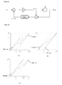
- FIG. 8 is a diagram for explaining the structure of a ⁇ converter.
- FIG. 9 (a) is a graph showing the map of the ( ⁇ , ⁇ ) expansion
- an object of the present invention is to provide a high-precision converter and the like that makes up instability of circuit elements, by paying attention to the relation between the Markov chain and ⁇ conversion.
- a third aspect in accordance with the present invention provides the converter according to the first or the second aspect, including matrix estimating means, if ⁇ /( ⁇ 2 -1) ⁇ ⁇ 2 /( ⁇ 2 -1), for approximating a Markov transition matrix to equation (eq3), if ⁇ ⁇ ⁇ /( ⁇ 2 -1), approximating a Markov transition matrix to equation (eq4), and if ⁇ 2 /( ⁇ 2 -1) ⁇ ⁇ , approximating a Markov transition matrix to equation (eq5).
- a fourth aspect in accordance with the present invention provides the converter according to any of the first to the third aspects, including matrix estimating means for estimating a 2 x 2 Markov transition matrix of the ⁇ conversion by equation (eq7) for n 00 , n 01 , n 10 , and n 11 given by equation (eq6).
- a fifth aspect in accordance with the present invention provides a program for making a computer function as the converter according to any of the first to the fourth aspects.
- a seventh aspect in accordance with the present invention provides a recording medium for recording the program according to the sixth aspect.
- FIG. 1 is a block diagram of a converter 1 according to an embodiment of the present invention.
- FIG. 2 is a flowchart for explaining the operation of the converter 1 of FIG. 1 .
- the converter 1 also includes a matrix estimation section 5 for obtaining the Markov transition matrix based on b i .
- a conversion error of the converter 1 is expressed as equation 3 as described below.
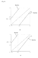
- FIGS. 3 (a) and 3 (b) are diagrams each showing the invariant subspace of the ⁇ conversion.
- FIG. 3 (a) is a diagram showing the case where ⁇ ( ⁇ -1) ⁇ ⁇
- FIG. 3 (b) is a diagram showing the case where ⁇ ⁇ ⁇ ( ⁇ -1).
- FIG. 4 is a diagram showing the distribution of eigenvalues when the Markov transition matrix is approximated.
- the second eigenvalue of the approximated transition matrix is negative.
- n 00 , n 01 , n 10 , and n 11 are defined by equations (20)
- an estimated Markov transition matrix is expressed by equation (21).
- FIG. 7 is a diagram showing a result of estimating a second eigenvalue.
- the second eigenvalue is negative, and the eigenvalues obtained by the greedy and lazy schemes are larger than those of the other scheme.
- the eigenvalues of the greedy and lazy schemes are similar to each other.
- a recommended value of the threshold is set to an intermediate value in a range from 1 to 1/( ⁇ -1) which is a permissible range of the parameter ⁇ .
- Hardware of the present invention can be realized by a configuration similar to that of FIG. 8 in spite of the difference of using equation (2) and the like.
Landscapes
- Engineering & Computer Science (AREA)
- Physics & Mathematics (AREA)
- Audiology, Speech & Language Pathology (AREA)
- Computational Linguistics (AREA)
- Signal Processing (AREA)
- Health & Medical Sciences (AREA)
- Human Computer Interaction (AREA)
- Acoustics & Sound (AREA)
- Multimedia (AREA)
- Theoretical Computer Science (AREA)
- Spectroscopy & Molecular Physics (AREA)
- Compression, Expansion, Code Conversion, And Decoders (AREA)
- Analogue/Digital Conversion (AREA)
Abstract

Description
- The present invention relates to a converter, a conversion method, a program, and a recording medium and, more particularly, to a converter and the like for performing conversion between a digital signal and an analog signal.
- With spread of digital signal process in recent years, A/D (D/A) converting process is performed in various fields of sound process, image process, communication and the like. Since the precision of the converting process exerts an influence on a result of the sound process and the like, higher level is being continuously demanded. For example, one of methods having high precision is PCM (pulse-code modulation). The PCM, however, has a drawback such that the stability of circuit elements in an A/D converter is insufficient. One of methods realizing stability of operation is ΣΔ (sigma-delta) modulation (refer to
Non-Patent Documents 1 to 7). There is also a technique called β conversion based on the sigma-delta modulation (refer to Patent Documents 8 and 9). - The β conversion will be described. When γ = 1/β (where 1 < β < 2), x∈ (0, 1) is expressed by equation (1) using bi∈{0, 1}. Here, u1 = βy, b1 = Qν(u1), and ui+1 = β(ui - bi), bi+1 = Qν (ui+1). Qν(z) denotes a quantizer and, for a threshold ν satisfying ν∈[1, (β-1)-1], is 0 when z < ν and is 1 when z ≥ ν.
-

-
FIG. 8 is a diagram for explaining the structure of a β converter. When z0 = y∈ [0, 1) and i > 0, zi = 0, and u0 = b0 = 0. In the β converter, when ν = 1, the greedy" scheme has been proposed. When ν = (β-1)-1, the "lazy" scheme has been proposed. - When α = ν-1 in the above, it can be said that in the β conversion, the (β, α) expansions proposed by Dajani et al. are performed (refer to Non-Patent Document 10). In a map Nβ,α of the (β, α) expansions with β∈ (1, 2), when x∈ [0, (α + 1) /β), βx is derived. When x∈ [(α + 1)/β, 1/(β-1)), βx-1 is derived.
-
FIG. 9 (a) is a graph showing the map of the (β, α) expansion,FIG. 9 (b) is a graph showing a "greedy" map when V = 1, andFIG. 9(c) is a graph showing a "lazy" map when ν = (β-1)-1. -
- Non-Patent
Document 1
Inose, H., and Yasuda, Y., "A unity bit coding method by negative feedback," Proceedings of the IEEE, vol. 51, no. 11, pp 1524-1535, Nov. 1963 - Non-Patent
Document 2
J. Candy, "A Use of Limit Cycle Oscillation to Obtain Robust Analog-to-Digital Converters," Communications, IEEE Transactions on [legacy, pre -1988], vol. 22, no. 3, pp 298-305, Mar. 1974 - Non-Patent
Document 3
Stephen H. Lewis, and Paul R. gray, "A pipelined 5-Msample/s 9-bit analog-to-digital converter," Solid-State Circuits, IEEE Journal of, vol. 22, no. 6, pp 954-961, Dec 1987 - Non-Patent Document 4
Robert M. Gray, "Oversampled Sigma-Delta Modulation," Communications, IEEE transactions on [legacy, pre-1988], vol. 35, no. 5, pp 481-489, May 1987 - Non-Patent Document 5
Robert M. Gray, "Spectral Analysis of Quantization Noise in a Single-Loop Sigma-Delta Modulator with dc Input," IEEE Transactions on communications, vol. 37, no. 6, pp 588-599, Jun. 1989 - Non-Patent Document 6
C. Gunturk, "On the robustness of single-loop sigma-delta modulation," IEEE Transactions on Information Theory, Vol. 47, no. 5, pp 1734-1744, 2001 - Non-Patent Document 7
C. Gunturk, "One-Bit Sigma-Delta Quantization with Exponential Accuracy, " Commun. Pure Applied Math., vol. 56, no. 11, pp 1608-1630, 2003 - Non-Patent Document 8
1. Daubechies, R. Devore, C. Gunturk, and V. Vaishampayan, "A/D Conversion With Imperfect Quantizers," IEEE Transcations on Information Theory, vol. 52, no. 3, pp. 874-885, Mar. 2006 - Non-Patent Document 9
I. Daubechies, and O. Yilmaz, "Robust and Practical Analog-to-Digital Conversion With Exponential Precision," IEEE Transactions on information Theory, vol. 52, no. 8, pp. 3533-3545, Aug. 2006 - Non-Patent Document 10
K. Dajani, C. Kraaikamp, "From greedy to lazy expansions and their driving dynamics," Expo. Math, 2002 - Although the β conversion has been studied mathematically as described above, study to apply it to A/D (D/A) converting process has been insufficient. In particular, there is still room for development for high precision required for converters and for making up the instability of circuit elements.
- Therefore, an object of the present invention is to provide a high-precision converter and the like that makes up instability of circuit elements, by paying attention to the relation between the Markov chain and β conversion.
- A first aspect in accordance with the present invention provides a converter for determining a decoded value of a sample value x based on L-bit number bi (i = 1, ..., L), including decoding means for determining a decoded value xD for γ = 1/β (where 1 < β < 2) by equation (eq1).
- A second aspect in accordance with the present invention provides the converter according to the first aspect, wherein when bit sequences obtained by β-converting x∈ (0, 1) and y = 1-x∈ (0,1) are L-bit numbers bi and ci (i = 1, ..., L), respectively, a decoded value xD of bi is expressed by equation (eq1), and a decoded value yD of ci is expressed by an equation derived by replacing bi in equation (eq1) with ci, γ is the root of an equation P(γ) = 0 given by equation (eq2).
- A third aspect in accordance with the present invention provides the converter according to the first or the second aspect, including matrix estimating means, if β/(β2-1) ≤ ν<β2/(β2-1), for approximating a Markov transition matrix to equation (eq3), if ν < β/(β2-1), approximating a Markov transition matrix to equation (eq4), and if β2/(β2-1) ≤ ν, approximating a Markov transition matrix to equation (eq5).
- A fourth aspect in accordance with the present invention provides the converter according to any of the first to the third aspects, including matrix estimating means for estimating a 2 x 2 Markov transition matrix of the β conversion by equation (eq7) for n00, n01, n10, and n11 given by equation (eq6).
- A fifth aspect in accordance with the present invention provides a conversion method for performing conversion between a digital signal and an analog signal for determining a decoded value of a sample value x based on L-bit number bi (i = 1, ..., L), including the step of making decoding means determine a decoded value xD for γ = 1/β (where 1 < β < 2) by equation (eq1) .
- A fifth aspect in accordance with the present invention provides a program for making a computer function as the converter according to any of the first to the fourth aspects.
- A seventh aspect in accordance with the present invention provides a recording medium for recording the program according to the sixth aspect.
-


- With the present invention, a high-precision D/A converter or the like that makes up for the instability of circuit elements by interval analysis of β expansions can be proposed.
- In the present invention, as a result of analyzing the β conversion as a Markov chain, it was found that a second eigenvalue is negative and that eigenvalues of greedy and lazy schemes are larger than that of any other map and are the same.
-
-
FIG. 1 is a block diagram of aconverter 1 according to an embodiment of the present invention. -
FIG. 2 is a flowchart for explaining the operation of the converter ofFIG. 1 . -
FIGS. 3(a) and 3(b) are diagrams showing the invariant subspace of β conversion. -
FIG. 4 is a diagram showing a distribution of eigenvalues when a Markov transition matrix is approximated. -
FIG. 5 is a diagram showing the worst precision of conversion when changing x and V for N = 32 and β = 1.77777. -
FIG. 6 is a diagram showing a case where the precision of restoring the value of β from an output bit sequence is determined by the relation of γ = 1/β and equations (11) and (12), and the proposed method and the method of Daubechies are compared. -
FIG. 7 is a diagram showing an estimation result of a second eigenvalue. -
FIG. 8 is a diagram for explaining the structure of a β converter. -
FIG. 9 (a) is a graph showing a map of a (β, α) expansion,FIG. 9 (b) is a graph showing a "greedy" map when V = 1, andFIG. 9(c) is a graph showing a "lazy" map when ν = (β-1)-1. -
- 1
- converter
- 3
- decoding section
- 5
- matrix estimation section
-
FIG. 1 is a block diagram of aconverter 1 according to an embodiment of the present invention.FIG. 2 is a flowchart for explaining the operation of theconverter 1 ofFIG. 1 . Theconverter 1 obtains a decoded value xD of a sample value x based on L-bit number bi (i = 1, ..., L) (see steps ST1 and ST3 inFIG. 2 ). Theconverter 1 includes adecoding section 3 which obtains a decoded value xD for γ = 1/β (where 1 < β < 2) using equation 2 (see step ST2 inFIG. 2 ). In the case of usingequation 1 described in the prior art, attention is paid to the lower limit of an interval. In contrast, in the case of usingequation 2, it is largely different with respect to the point that attention is paid to the center of an interval. Theconverter 1 also includes a matrix estimation section 5 for obtaining the Markov transition matrix based on bi. - A conversion error of the
converter 1 is expressed asequation 3 as described below. - First, an interval Ii is defined as equation 4 (where b0 = 0).
- Subsequently, it is shown that x∈Ii for all i . From x∈ (0, 1), x∈I0 = (0, (β-1)-1).
- It is now supposed that x∈Ii. When ui+1 < ν as shown in equation 5, that is, when bi+1 = 0, equation (6) is satisfied and x∈Ii+1. On the other hand, when ui+1 ≥ V, that is, when bi+1 = 1, equation (7) is satisfied and x∈Ii+1. Therefore, x∈Ii is satisfied for all i.
- Since it can be expressed that x∈IL and (β-1)-1 = Σi=1 ∞γi, a conversion error is expressed by equation (8).
-


- According to the A/D conversion of Daubechies, et al., in the case where β > 1.5, an error which occurs in L-bit β conversion is expressed by equation (9).
-

- Subsequently, a characteristic equation of β will be described.
- With reference to Daubechies et al, if bit sequences obtained by β-converting x∈(0, 1) and y = 1-x∈(0, 1) are bi and ci (i = 1, ..., N), respectively, each of the decoded values xD and yD are expressed by equation (10).
- From xD + yD = 1, the estimated value of γ is the root of a characteristic equation P(γ) = 0 of γ given by equation (11).
- The characteristic equation PDau(γ) = 0 of Daubechies et al. is given by equation (12).
-


- The Markov chain of binary sequences generated by β conversion will now be described. Let bi (i = 1, ..., N) be a binary sequence generated by β conversion with β and a threshold ν.
- It is shown here that an invariant subspace of the β conversion denoted by I = (β(ν-1), βν) exists. There are two integers k and k' such that ui < ui+1 < ... < ui+k-1 < β(ν-1) < ui+k and ui > ui+1 > ... > ui+k'-1 < βν < ui+k' are satisfied, which implies that ui∈(β(ν-1), βν).
FIGS. 3 (a) and 3 (b) are diagrams each showing the invariant subspace of the β conversion.FIG. 3 (a) is a diagram showing the case where β(ν-1) ≤ νλ, andFIG. 3 (b) is a diagram showing the case where ν < λβ(ν-1). - The invariant space of the β conversion exists. However, it is difficult to divide the subinterval into Markov partitions. Therefore, bi is approximated with a two-state Markov chain (1st-order Markov chain), and an eigenvalue of the Markov transition matrix is analyzed.
- S and T are defined by equations (13) and (14), respectively. The matrix estimation section 5 in
FIG. 1 approximates the transition matrix as follows. - If β/(β2-1) ≤ ν < β2/(β2-1), the transition matrix is approximated to become equation (15). Since S > 0 and T > 0, a second eigenvalue λ satisfies the relation λ < 0 from equation (16). A frequency distribution is given by an eigenvector for the
eigenvalue 1, that is, equation (17). - If ν < β/(β2-1), the transition matrix is approximated to become equation (18). The second eigenvalue λ is expressed as λ = -S/(βT) < 0.
- If β2/(β2-1) ≤ ν, the transition matrix is approximated to become equation (19). The second eigenvalue λ is expressed as λ = -T/(βS) < 0.
-


-
FIG. 4 is a diagram showing the distribution of eigenvalues when the Markov transition matrix is approximated. The second eigenvalue of the approximated transition matrix is negative. - The matrix estimation section 5 in
FIG. 1 estimates a 2 x 2 Markov transmission matrix of the β conversion with bi (i = 1, ..., N). When n00, n01, n10, and n11 are defined by equations (20), an estimated Markov transition matrix is expressed by equation (21). -


- In the following, the conversion using the proposed algorism will be compared with the method of Daubechies. The worst approximation error between x and the decoded value xD when moving x and a quantization threshold ν (cautious parameter) is criteria for evaluation.
FIG. 5 is a diagram showing the worst precision of conversion when changing x and ν for N = 32 and β = 1.77777. It is understood fromFIG. 5 that the precision of the proposed algorithm is superior to that of the algorism of Daubechies when β = 1.77777. It is also known that the cautious scheme has higher precision than the other scheme in the proposed algorithm. -
FIG. 6 is a diagram showing a case where the precision of restoring the value of β from an output bit sequence is determined by the relation of γ = 1/β, equations (11) and (12), and the proposed method and the method of Daubechies are compared. It is shown in the diagram that the β restoring precision of the proposed method is higher. - Estimation of a second eigenvalue of the two-state Markov transition matrix will now be described. By the β conversion with β∈ (1,2), ν∈[1, (β-1)-1], and x∈ (0, (β-1)-1), a binary bit sequence bi (i = 1, ..., N) is outputted, and it is assumed that bi is a two-state Markov chain. At this time, a second eigenvalue can be estimated from bi by equation (21).
FIG. 7 is a diagram showing a result of estimating a second eigenvalue. λD is a second eigenvalue estimated from bi under condition that N = 256 and x = ν-π/10. From the diagram, it is shown that most second eigenvalues are negative. It is understood fromFIG. 7 that most λD values obtained by the greedy and lazy schemes are larger than values obtained by the cautious scheme and are similar values. - From the above, as a result of analyzing the β conversion as the Markov chain, the second eigenvalue is negative, and the eigenvalues obtained by the greedy and lazy schemes are larger than those of the other scheme. The eigenvalues of the greedy and lazy schemes are similar to each other.
- Preferably, a recommended value of the threshold is set to an intermediate value in a range from 1 to 1/(β-1) which is a permissible range of the parameter ν. The reason is that, although it is conventionally said that the restoration precision of the greedy scheme is higher than that of the lazy scheme, when ν = (1 + 1/(β-1))/2 is set, the restoration precision of the lazy scheme and that of the greedy scheme are equivalent, and excellent results are obtained from the viewpoint of the result of the precision and the viewpoint of robustness.
- Hardware of the present invention can be realized by a configuration similar to that of
FIG. 8 in spite of the difference of using equation (2) and the like.
Claims (7)
- A converter for determining a decoded value of a sample value x based on L-bit number bi (i = 1, ..., L),
comprising decoding means for determining a decoded value xD for γ = 1/β (where 1 < β < 2) by equation (eq1).
- The converter according to claim 1, wherein when bit sequences obtained by β-converting x∈(0, 1) and y = 1-x∈(0,1) are L-bit numbers bi and ci (i = 1, ..., L), respectively, and when xD, a decoded value of bi, is expressed by equation (eq1), and yD, a decoded value of ci, is expressed by an equation derived by replacing bi in equation (eq1) with ci, γ is the root of an equation P(γ) = 0 given by equation (eq2).

- The converter according to claim 1 or 2, comprising matrix estimating means, if β/(β2-1) ≤ ν < β2/(β2-1), for approximating a Markov transition matrix to equation (eq3), if ν < β/(β2-1), approximating a Markov transition matrix to equation (eq4), and if β2/(β2-1) ≤ ν, approximating a Markov transition matrix to equation (eq5).


- The converter according to any of claims 1 to 3, comprising matrix estimating means for estimating a 2 x 2 Markov transition matrix of the β conversion by equation (eq7) for n00, n01, n10, and n11 given by equation (eq6).


- A conversion method for performing conversion between a digital signal and an analog signal for determining a decoded value of a sample value x based on L-bit number bi (i = 1, ..., L), comprising the step of making decoding means determine a decoded value xD for γ = 1/β (where 1 <β<2) by equation (eq8).

- A program for making a computer function as the converter of any of claims 1 to 4.
- A recording medium for recording the program of claim 6.
Applications Claiming Priority (2)
| Application Number | Priority Date | Filing Date | Title |
|---|---|---|---|
| JP2007189899 | 2007-07-20 | ||
| PCT/JP2008/062897 WO2009014057A1 (en) | 2007-07-20 | 2008-07-17 | Converter, conversion method, program, and recording medium |
Publications (2)
| Publication Number | Publication Date |
|---|---|
| EP2169832A1 true EP2169832A1 (en) | 2010-03-31 |
| EP2169832A4 EP2169832A4 (en) | 2012-07-25 |
Family
ID=40281313
Family Applications (1)
| Application Number | Title | Priority Date | Filing Date |
|---|---|---|---|
| EP08778239A Withdrawn EP2169832A4 (en) | 2007-07-20 | 2008-07-17 | CONVERTER, CONVERSION METHOD, PROGRAM, AND RECORDING MEDIUM |
Country Status (6)
| Country | Link |
|---|---|
| US (1) | US7994952B2 (en) |
| EP (1) | EP2169832A4 (en) |
| JP (1) | JP5076248B2 (en) |
| KR (1) | KR101109614B1 (en) |
| TW (1) | TWI433469B (en) |
| WO (1) | WO2009014057A1 (en) |
Families Citing this family (5)
| Publication number | Priority date | Publication date | Assignee | Title |
|---|---|---|---|---|
| US20110193734A1 (en) * | 2008-08-25 | 2011-08-11 | Japan Science And Technology Agency | Signal converter, parameter deciding device, parameter deciding method, program, and recording medium |
| EP2555433A4 (en) | 2010-04-01 | 2014-06-04 | Japan Science & Tech Agency | METHOD OF CONVERTING DATA BASED ON -MAP SCALE |
| WO2011125297A1 (en) | 2010-04-06 | 2011-10-13 | 独立行政法人科学技術振興機構 | DATA CONVERSION METHOD BASED ON NEGATIVE β-MAP |
| JP5436508B2 (en) * | 2011-09-22 | 2014-03-05 | 独立行政法人科学技術振興機構 | Analog-to-digital converter and method for converting an analog signal into a digital signal |
| JP6205215B2 (en) * | 2013-09-09 | 2017-09-27 | オリンパス株式会社 | Imaging device |
Family Cites Families (5)
| Publication number | Priority date | Publication date | Assignee | Title |
|---|---|---|---|---|
| US5099450A (en) * | 1988-09-22 | 1992-03-24 | Syracuse University | Computer for reducing lambda calculus expressions employing variable containing applicative language code |
| FI86120C (en) * | 1990-07-02 | 1992-07-10 | Nokia Mobile Phones Ltd | A / D- ELLER D / A-OMVANDLARE, A / D- ELLER D / A-OMVANDLARSYSTEM SAMT KALIBRERINGSFOERFARANDE FOER DESSA. |
| EP1063807B1 (en) * | 1999-06-18 | 2004-03-17 | Alcatel | Joint source-channel coding |
| JP2001196932A (en) * | 2000-01-07 | 2001-07-19 | Kenwood Corp | D / A converter |
| US7602323B2 (en) * | 2007-04-04 | 2009-10-13 | The Regents Of The University Of California | Digital background correction of nonlinear error ADC's |
-
2008
- 2008-07-17 EP EP08778239A patent/EP2169832A4/en not_active Withdrawn
- 2008-07-17 JP JP2009524464A patent/JP5076248B2/en not_active Expired - Fee Related
- 2008-07-17 TW TW097127069A patent/TWI433469B/en not_active IP Right Cessation
- 2008-07-17 KR KR1020097023935A patent/KR101109614B1/en not_active Expired - Fee Related
- 2008-07-17 WO PCT/JP2008/062897 patent/WO2009014057A1/en not_active Ceased
- 2008-07-17 US US12/669,860 patent/US7994952B2/en not_active Expired - Fee Related
Also Published As
| Publication number | Publication date |
|---|---|
| WO2009014057A8 (en) | 2009-10-22 |
| US7994952B2 (en) | 2011-08-09 |
| JPWO2009014057A1 (en) | 2010-09-30 |
| TWI433469B (en) | 2014-04-01 |
| JP5076248B2 (en) | 2012-11-21 |
| KR20100010504A (en) | 2010-02-01 |
| TW200915733A (en) | 2009-04-01 |
| WO2009014057A1 (en) | 2009-01-29 |
| KR101109614B1 (en) | 2012-01-31 |
| US20100207796A1 (en) | 2010-08-19 |
| EP2169832A4 (en) | 2012-07-25 |
Similar Documents
| Publication | Publication Date | Title |
|---|---|---|
| US6269135B1 (en) | Digital phase discriminations based on frequency sampling | |
| Klimesh | Low-complexity lossless compression of hyperspectral imagery via adaptive filtering | |
| US7994952B2 (en) | Converter, conversion method, program, and recording medium | |
| US5838272A (en) | Error correcting sigma-delta modulation decoding | |
| US8909521B2 (en) | Coding method, coding apparatus, coding program, and recording medium therefor | |
| CN101034870A (en) | Digital phase discrimination based on frequency sampling | |
| US10133551B1 (en) | Content-aware compression of data using multiple parallel prediction functions | |
| US20130082850A1 (en) | Data encoding apparatus, data decoding apparatus and methods thereof | |
| CN110491398B (en) | Encoding method, encoding device, and recording medium | |
| Shehab et al. | Recurrent neural network based prediction to enhance satellite telemetry compression | |
| EP3859976B1 (en) | Coding device, decoding device, code string data structure, coding method, decoding method, coding program, and decoding program | |
| CN1286854A (en) | Digital phase discrimination based on frequency sampling | |
| JP4702645B2 (en) | Arithmetic apparatus and method, quantization apparatus and method, and program | |
| EP3902141B1 (en) | Encoding device, decoding device, encoding method and decoding method, and program | |
| CN119629369A (en) | An image coding method and system based on generalized Gaussian model | |
| EP2320571A1 (en) | Signal converter, parameter deciding device, parameter deciding method, program, and recording medium | |
| CN115603747A (en) | Quantization method, analog-to-digital converter, electronic device, and computer-readable storage medium | |
| Maréchal et al. | Optimal filtering of an incremental second-order MASH11 sigma-delta modulator | |
| Nguyen et al. | Compression of wideband IQ samples using linear predictive coding and frame of reference | |
| GB2320386A (en) | Encoding the contour of an object in a video signal encoder | |
| JPH03117034A (en) | Over sampling type analog/digital converter | |
| Benedetto et al. | Pointwise comparison of PCM and Σ Δ quantization | |
| CN115968532B (en) | Efficient codec for electrical signals | |
| US10848176B1 (en) | Digital delta-sigma modulator with non-recursive computation of residues | |
| EP3780396B1 (en) | Encoding device, decoding device, encoding method, decoding method, program, and recording medium |
Legal Events
| Date | Code | Title | Description |
|---|---|---|---|
| PUAI | Public reference made under article 153(3) epc to a published international application that has entered the european phase |
Free format text: ORIGINAL CODE: 0009012 |
|
| 17P | Request for examination filed |
Effective date: 20091117 |
|
| AK | Designated contracting states |
Kind code of ref document: A1 Designated state(s): AT BE BG CH CY CZ DE DK EE ES FI FR GB GR HR HU IE IS IT LI LT LU LV MC MT NL NO PL PT RO SE SI SK TR |
|
| AX | Request for extension of the european patent |
Extension state: AL BA MK RS |
|
| DAX | Request for extension of the european patent (deleted) | ||
| A4 | Supplementary search report drawn up and despatched |
Effective date: 20120622 |
|
| RIC1 | Information provided on ipc code assigned before grant |
Ipc: H03M 1/06 20060101ALI20120618BHEP Ipc: H03M 1/08 20060101ALI20120618BHEP Ipc: H03M 1/66 20060101AFI20120618BHEP |
|
| RAP1 | Party data changed (applicant data changed or rights of an application transferred) |
Owner name: KYUSHU UNIVERSITY, NATIONAL UNIVERSITY CORPORATION |
|
| RIC1 | Information provided on ipc code assigned before grant |
Ipc: H03M 1/08 20060101AFI20140429BHEP Ipc: G10L 19/02 20130101ALI20140429BHEP Ipc: H03M 1/06 20060101ALI20140429BHEP Ipc: H03M 1/66 20060101ALN20140429BHEP Ipc: G10L 19/00 20130101ALI20140429BHEP |
|
| GRAP | Despatch of communication of intention to grant a patent |
Free format text: ORIGINAL CODE: EPIDOSNIGR1 |
|
| RIC1 | Information provided on ipc code assigned before grant |
Ipc: H03M 1/06 20060101ALI20140514BHEP Ipc: G10L 19/02 20130101ALI20140514BHEP Ipc: H03M 1/66 20060101ALN20140514BHEP Ipc: H03M 1/08 20060101AFI20140514BHEP Ipc: G10L 19/00 20130101ALI20140514BHEP |
|
| INTG | Intention to grant announced |
Effective date: 20140606 |
|
| RIC1 | Information provided on ipc code assigned before grant |
Ipc: G10L 19/02 20130101ALI20140528BHEP Ipc: H03M 1/06 20060101ALI20140528BHEP Ipc: H03M 1/08 20060101AFI20140528BHEP Ipc: H03M 1/66 20060101ALN20140528BHEP Ipc: G10L 19/00 20130101ALI20140528BHEP |
|
| RIN1 | Information on inventor provided before grant (corrected) |
Inventor name: KOHDA, TOHRU Inventor name: AIHARA, KAZUYUKI Inventor name: HIRONAKA, SATOSHI |
|
| STAA | Information on the status of an ep patent application or granted ep patent |
Free format text: STATUS: THE APPLICATION IS DEEMED TO BE WITHDRAWN |
|
| 18D | Application deemed to be withdrawn |
Effective date: 20141017 |