EP2169779A1 - Electromagnetic shield for an electrical connector, and an electrical connector - Google Patents
Electromagnetic shield for an electrical connector, and an electrical connector Download PDFInfo
- Publication number
- EP2169779A1 EP2169779A1 EP09167457A EP09167457A EP2169779A1 EP 2169779 A1 EP2169779 A1 EP 2169779A1 EP 09167457 A EP09167457 A EP 09167457A EP 09167457 A EP09167457 A EP 09167457A EP 2169779 A1 EP2169779 A1 EP 2169779A1
- Authority
- EP
- European Patent Office
- Prior art keywords
- shield
- region
- electrical connector
- crimp
- overlap
- Prior art date
- Legal status (The legal status is an assumption and is not a legal conclusion. Google has not performed a legal analysis and makes no representation as to the accuracy of the status listed.)
- Withdrawn
Links
Images

Classifications
-
- H—ELECTRICITY
- H01—ELECTRIC ELEMENTS
- H01R—ELECTRICALLY-CONDUCTIVE CONNECTIONS; STRUCTURAL ASSOCIATIONS OF A PLURALITY OF MUTUALLY-INSULATED ELECTRICAL CONNECTING ELEMENTS; COUPLING DEVICES; CURRENT COLLECTORS
- H01R13/00—Details of coupling devices of the kinds covered by groups H01R12/70 or H01R24/00 - H01R33/00
- H01R13/46—Bases; Cases
- H01R13/502—Bases; Cases composed of different pieces
- H01R13/506—Bases; Cases composed of different pieces assembled by snap action of the parts
-
- H—ELECTRICITY
- H01—ELECTRIC ELEMENTS
- H01R—ELECTRICALLY-CONDUCTIVE CONNECTIONS; STRUCTURAL ASSOCIATIONS OF A PLURALITY OF MUTUALLY-INSULATED ELECTRICAL CONNECTING ELEMENTS; COUPLING DEVICES; CURRENT COLLECTORS
- H01R13/00—Details of coupling devices of the kinds covered by groups H01R12/70 or H01R24/00 - H01R33/00
- H01R13/648—Protective earth or shield arrangements on coupling devices, e.g. anti-static shielding
- H01R13/658—High frequency shielding arrangements, e.g. against EMI [Electro-Magnetic Interference] or EMP [Electro-Magnetic Pulse]
- H01R13/6591—Specific features or arrangements of connection of shield to conductive members
- H01R13/6592—Specific features or arrangements of connection of shield to conductive members the conductive member being a shielded cable
- H01R13/6593—Specific features or arrangements of connection of shield to conductive members the conductive member being a shielded cable the shield being composed of different pieces
-
- H—ELECTRICITY
- H01—ELECTRIC ELEMENTS
- H01R—ELECTRICALLY-CONDUCTIVE CONNECTIONS; STRUCTURAL ASSOCIATIONS OF A PLURALITY OF MUTUALLY-INSULATED ELECTRICAL CONNECTING ELEMENTS; COUPLING DEVICES; CURRENT COLLECTORS
- H01R13/00—Details of coupling devices of the kinds covered by groups H01R12/70 or H01R24/00 - H01R33/00
- H01R13/56—Means for preventing chafing or fracture of flexible leads at outlet from coupling part
- H01R13/567—Traverse cable outlet or wire connection
-
- H—ELECTRICITY
- H01—ELECTRIC ELEMENTS
- H01R—ELECTRICALLY-CONDUCTIVE CONNECTIONS; STRUCTURAL ASSOCIATIONS OF A PLURALITY OF MUTUALLY-INSULATED ELECTRICAL CONNECTING ELEMENTS; COUPLING DEVICES; CURRENT COLLECTORS
- H01R13/00—Details of coupling devices of the kinds covered by groups H01R12/70 or H01R24/00 - H01R33/00
- H01R13/648—Protective earth or shield arrangements on coupling devices, e.g. anti-static shielding
- H01R13/658—High frequency shielding arrangements, e.g. against EMI [Electro-Magnetic Interference] or EMP [Electro-Magnetic Pulse]
- H01R13/6581—Shield structure
- H01R13/6582—Shield structure with resilient means for engaging mating connector
- H01R13/6583—Shield structure with resilient means for engaging mating connector with separate conductive resilient members between mating shield members
Definitions
- the invention relates to an electromagnetic shield for an electrical connector, in particular an electrical plug connector such as for example a pin or socket connector, with at least two shield parts connectable to one another. Furthermore, the invention relates to an electrical connector for the motor vehicle or consumer goods sector, with an electromagnetic shield according to the invention, wherein the electrical connector has at least two, preferably external, shield parts.
- Modern motor vehicles have a plurality of electric and electronic devices, such as for example control apparatus, which communicate in a bus- and/or network-oriented manner with an engine management system or a computer for management of the motor vehicle. A corresponding transfer of data takes place in this case, preferably digitally.
- These devices are assigned to functional units of the vehicle, such as for example a chassis control system, power train control system, entertainment system or telematics. To ensure communication between the functional units of the vehicle, corresponding electrical connectors, in particular plug connectors, are necessary.
- Such crimp connections of electromagnetic shields with braids are reliable as they are based on proven technology, they are of simple and robust construction, and after the setting of a crimping tool can always achieve qualitatively identical connections. Furthermore they are economical, as they can be manufactured at low cost and with low wastage, they are easy to operate and are versatile in use, as they permit a plurality of individual solutions.
- Such crimpable electromagnetic shields are constructed in two parts, wherein the hollow-cylindrical crimp portion of the two shield parts of the shield is composed of two half shells, which rest against one another on two abutting edges.
- the electrically insulated leads of the electric cable are arranged inside the crimp portion, and the braid is pulled onto the crimp portion externally.
- a crimp barrel is pushed over the crimp portion and the braid, which barrel is crimped by means of the crimping tool, whereby an electrically conductive connection is produced between the braid and the shield of the electrical connector.
- One object of the invention is to provide an improved electromagnetic shield for an electrical connector of an electric cable. Furthermore, it is an object of the invention to provide an improved electrical connector, in particular an improved cable to cable electrical plug connector.
- an improved electrical connector in particular an improved cable to cable electrical plug connector.
- a crimp portion that is more dimensionally stable on crimping should be provided in this case on the shield, so that the braid of the cable cannot penetrate inwards into the crimp portion on crimping. This should be realized as economically as possible, wherein in particular an already existing shield of an electrical connector must be redesigned as little as possible, so that previous tools can be used for its manufacture.
- the object of the invention is achieved by means of an electromagnetic shield for an electrical connector, in particular an electrical plug connector, according to claim 1; and an electrical connector, in particular an electrical pin or socket connector for the motor vehicle or consumer goods sector, with an electromagnetic shield according to the invention, according to claim 11.
- the electromagnetic shield for the electrical connector has two shield parts connectable to one another, wherein in a crimp portion of the electromagnetic shield, one shield part has a positioning projection, and the positioning projection of one shield part can be inserted into or applied to a positioning recess of the other shield part.
- the positioning projection is an region of one shield part
- the positioning recess is defined by an region of the other shield part, wherein in the assembled state of the two shield parts these two regions form an overlap portion of the shield, in which section the latter is formed with a double wall.
- the crimp portion is closed in a circumferential direction and has a substantially circular or elliptical cross-section. Other cross-sectional shapes can naturally be used.
- the positioning projection and the positioning recess preferably extend in this case substantially in a circumferential direction and also along a longitudinal axis of the crimp portion of the electromagnetic shield.
- the positioning projection of one shield part is formed in particular as a tooth, a peg or a lug, and the positioning recess of the other shield part has a shape that preferably at least partially corresponds to it and is formed for example as a pocket, a seam or an impression.
- the profiles of the positioning projection and the positioning recess are configured in this case preferably without an undercut.
- the positioning recess can also consist only of an inner or outer free space of the crimp portion.
- a positioning projection as well as an appropriate positioning recess is provided on one or a plurality of abutting edges of the crimp portion, i.e. adjacent to that region of the crimp portion in which the two shield parts meet one another.
- a plurality of positioning projections and positioning recesses corresponding to one another can be provided in this case along a single abutting edge.
- one, two or a plurality of positioning projections and positioning recesses corresponding to one another can be provided on a single crimp portion. It is preferable here that at least two positioning projections, preferably lying substantially opposite one another with reference to the longitudinal axis of the crimp portion, and positioning recesses assigned to these are provided. Furthermore, at least two positioning projections and positioning recesses assigned to these can be provided on each abutting edge.
- one or a plurality of positioning projections and positioning recesses assigned to these is/are formed or provided in such a way that for an abutting edge a mutual shift in both radial directions of the sections of the shield parts forming the crimp portion is prevented.
- the positioning recess assigned to this can be formed as a pocket that is closed in a radial direction.
- the positioning recesses are formed as seams or similar, i.e. if these are closed only in one radial direction of the crimp portion, then at least two positioning projections and positioning recesses corresponding to one another are necessary for each abutting edge to prevent a shift of the two shield parts in both radial directions.
- one positioning projection sits inside in a radial direction and one outside in a radial direction on the crimp portion. This means that the overlap portions have a differently offset overlap of the two regions of the shield parts.
- the at least two positioning projections can be provided in this case on a single shield part or distributed on both shield parts.
- the electrical connector according to the invention has an electromagnetic shield according to the invention as described above, which is preferably formed as an outer shield with two shield parts. If more than two shield parts should be present, which each contribute an region to the crimp portion of the shield, it is naturally possible to apply the above embodiments not only to two but also to a plurality of shield parts.
- the electrical connector can be formed as an electrical elbow connector, which preferably has an angle of 45° or 90°.
- the electromagnetic shield of the electrical connector Due to the double-walled formation of the electromagnetic shield of the electrical connector extending partly in the circumferential direction and at least in sections in the longitudinal direction of the crimp portion, it is possible to obtain a more dimensionally stable crimp portion, which no longer becomes so strongly deformed on crimping as crimp portions according to the prior art. It can hereby be prevented according to the invention that a braid of a cable shield can get inside the crimp portion on crimping, due to which short circuits on/in the electrical connector are effectively prevented.
- the invention is explained in greater detail below with reference to a 10-pin electrical 90° elbow plug connector with an electromagnetic shield according to the invention shown in the drawing, for the automotive industry.
- the invention is not to be limited to such a plug connector, however, but to be applicable to all electrical connectors that have a shield.
- the shield of the electrical connector is an external shield, as shown in the drawing; on the contrary, it is possible according to the invention for the shield to be arranged inside a housing of an electrical connector.
- Figs. 1 and 2 show an embodiment of an electrical connector 1 according to the invention with an electromagnetic shield 20 according to the invention, which connector can be formed for example as a cable to cable pin connector 1 or socket connector 1.
- the electrical connector 1 comprises a connector body 30, which is substantially completely surrounded outside by the two-part shield 20 apart from an end face 32 accessible for electrical contacts.
- the shield 20 has two shield parts 100, 200, which can be formed for example as shield plates 100, 200 or as shield plate halves 100, 200.
- the two shield parts 100, 200 are connectable to one another via a mechanical connection 40, preferably a catch mechanism 40, and in the fixed state in relation to one another have substantially the form of a rectangular parallelepiped in the region of the actual electrical connector 1.
- the catch mechanism 40 is configured in such a way that the shield part 100 has catching recesses 140 and the shield part 200 catching projections 240 corresponding thereto. Both the catching recesses 140 and the catching projections 240 can be provided in/on flaps protruding from the respective shield part 100, 200.
- the electromagnetic shield 20 has a crimp portion 22 composed of the two shield parts 100, 200 for an electric cable not shown in the drawing.
- the crimp portion 22 passing into the parallelepiped region of the shield 20 has in this case substantially the form of a hollow cylinder closed in the circumferential direction U with a substantially circular or elliptical cross-section.
- a longitudinal direction L of the crimp portion 22 lies substantially perpendicular to a plug-in direction S of the electrical connector 1.
- the crimp portion 22 of the electrical connector 1 and the electromagnetic shield 20 is composed of two substantially half-hollow-cylindrical crimp subportions 120, 220 of the two shield parts 100, 200.
- the two crimp subportions 120, 220 rest on one another on two abutting edges 26. It is naturally possible according to the invention that the two crimp subportions 120, 220 do not each cover approx. 180° in circumferential direction U, but another circumferential angle in each case, adding up in total to approx. 360°. It is likewise possible to assemble the crimp portion 22 not only from two crimp subportions 120, 220 but also from a plurality thereof. In this case even more than two shield parts 100, 200 can be provided.
- the electric cable can be fixed on the crimp portion 22 of the electrical connector 1 by a longitudinal end section.
- the longitudinal end section of the cable, stripped up to a braid or a shield, is positioned on/in the crimp portion 22 in such a way that on the one hand the braid comes to lie externally on the crimp portion 22 in circumferential direction U and the electric leads of the cable are arranged inside the crimp portion 22.
- a crimp barrel likewise not shown in the drawing, is pushed over the braid and the crimp portion 22, which barrel is pressed together by means of a crimping tool in a radial direction R of the crimp portion 22 such that the braid, the crimp portion 22 and the electric leads of the cable are fixed on one another by the crimp barrel.
- the plastically deformed crimp barrel holds this combination in a fixed state in relation to one another.
- the crimp portion has a configuration according to the invention.
- at least one region 122 of one shield part 100 and one region 222 of the other shield part 200 overlap in one section and on an abutting edge 26 in a so-called overlap portion 24, which extends at least partly in the circumferential direction U of the crimp portion 22.
- at least one such overlap portion 24 is provided for each abutting edge 26.
- a plurality of embodiments are possible to configure those two regions 122, 222, which form a single overlap portion 24 of the two crimp subportions 120, 220.
- a positioning projection 122 such as for example a tooth 122, a peg 122 or a lug 122
- a positioning recess 222 such as for example a pocket 222 (open or closed in the radial direction R)
- a seam 222 or an impression 222 is applicable.
- the positioning recess 222 can also be dispensed with, which can depend on the crimping tool used.
- Figs. 1 and 2 One such embodiment is shown explicitly in the drawing ( Figs. 1 and 2 ), a second one is shown dashed (only Fig. 1 ) and a third is shown dotted (likewise only Fig. 1 ).
- the regions 122, 222 concerned are positioning projections 122 and positioning recesses 222 corresponding to one another, which preferably extend in the circumferential direction U of the crimp portion 22.
- the positioning projections 122 and the positioning recesses 222 are configured in a tooth-like manner, wherein the positioning recesses 222 are configured somewhat larger in the relevant dimensions than the positioning projections 122. Furthermore, both preferably have an undercut-free profile in radial direction R, can therefore be fitted into or onto one another without any problem.
- the positioning recess 222 is instead an extended seam 50. The invention is hereby easily applicable to existing shield parts 200.
- the shield part 100 has two positioning projections 122 on its crimp subportion 120 in the region of an abutting edge 26 ( Fig. 1 ) and a single positioning projection 122 in the region of the abutting edge 26 lying opposite this ( Fig. 2 ).
- the shield part 200 has two positioning recesses 222 on its crimp subportion 220 in the region of the first abutting edge 26 ( Fig. 1 ) and a single positioning recess 222 in the region of the second abutting edge 26 ( Fig. 2 ).
- a single positioning recess or a plurality of positioning recesses 222 in radial direction R can be open pockets 222 or seams 222.
- the respective positioning projections 122 protrude from the crimp subportion 120 in circumferential direction U, downwards with reference to the drawing, from the respective abutting edge 26 and extend into the positioning recesses 222, which are open outwards in a radial direction R and closed inwards and which likewise extend in circumferential direction U. Due to this, the crimp subportion 120 can no longer shift inwards into the crimp portion 22 with reference to the crimp subportion 220 in the region of the abutting edges 26.
- overlap portions 24 Another number and/or distribution of these overlap portions 24 is naturally applicable. Thus it is possible for example depending on a length of the crimp portion 22 to provide only a single overlap portion or a plurality of overlap portions 24 of the two crimp subportions 120, 220 for each abutting edge 26. Quite generally the number of overlap portions 24 for each abutting edge 26 is freely selectable. It is also possible according to the invention to close the positioning recesses 222 in both radial directions R and in longitudinal direction L at least partly, so that even a movement of the crimp subportion 120 outwards in relation to the crimp subportion 220 is no longer possible.
- both shield parts 100, 200 have on each or only on one abutting edge 26 at least one positioning projection 122 and at least one positioning recess 222 corresponding thereto.
- the embodiment shown in figure 1 shows on a side lying opposite the end face 32 of the electrical connector 1 two positioning projections 120 on crimp subportion 120 and a single positioning projection 120 on the other crimp subportion 220.
- the single positioning projection 122 is arranged between the two other positioning projections 122.
- An region can be formed by analogy on the other abutting edge 26.
- all positioning recesses 222 are accessible from outside (therefore from outside the crimp portion 22) for the positioning projections 122.
- This can be configured differently, however. It is thus possible for example to arrange only a single positioning projection or a plurality or all positioning projections 122 and their corresponding positioning recesses 222 in such a way that the positioning projections 122 can engage in the relevant positioning recesses 222 inside the crimp portion 22.
- a crimp subportion 120, 220 can be slotted also in circumferential direction U, so that the other crimp subportion 220, 120 is pluggable with a radial section into this slot in such a way that the walls of the crimp subportions 120, 220 are arranged offset in parallel to one another and thus a mutual shift in both radial directions can be prevented.
- the positioning recess 222 When using a lug 122 as a positioning projection 122 in particular, it is possible to omit the positioning recess 222; i.e. the lug 122 concerned simply rests on the crimp subportion 220. Furthermore, the positioning recess 222 in this case can be formed as an impression 122.
- the crimp subportion 220 can be slotted in circumferential direction U, wherein a circumferential section of the crimp subportion 220 that has been cut free is then bent radially outwards and the positioning recess 222 is obtained thus. This is also possible with slots of the crimp subportion in circumferential direction U and longitudinal direction L.
- the two shield parts 100, 200 are configured in such a way that the positioning projections 112 are provided on that shield part 100 that also has the catching recesses 140 for the catch mechanism 40 of the two shield parts 100, 200.
Abstract
The invention relates to an electromagnetic shield for an electrical connector (1), in particular an electrical plug connector (1), with two shield parts (100, 200) connectable to one another, wherein
in a crimp portion (22) of the electromagnetic shield (20), an region (122) of one shield part (100) and an region (222) of the other shield part (100) overlap in an overlap portion (24).
in a crimp portion (22) of the electromagnetic shield (20), an region (122) of one shield part (100) and an region (222) of the other shield part (100) overlap in an overlap portion (24).
Furthermore, the invention relates to an electrical connector, in particular an electrical pin (1) or socket connector (1) for the automotive or consumer goods sector, with an electromagnetic shield (20) according to the invention, wherein the electrical connector (1) has at least two, preferably external, shield parts (100, 200).
Description
- The invention relates to an electromagnetic shield for an electrical connector, in particular an electrical plug connector such as for example a pin or socket connector, with at least two shield parts connectable to one another. Furthermore, the invention relates to an electrical connector for the motor vehicle or consumer goods sector, with an electromagnetic shield according to the invention, wherein the electrical connector has at least two, preferably external, shield parts.
- Modern motor vehicles have a plurality of electric and electronic devices, such as for example control apparatus, which communicate in a bus- and/or network-oriented manner with an engine management system or a computer for management of the motor vehicle. A corresponding transfer of data takes place in this case, preferably digitally. These devices are assigned to functional units of the vehicle, such as for example a chassis control system, power train control system, entertainment system or telematics. To ensure communication between the functional units of the vehicle, corresponding electrical connectors, in particular plug connectors, are necessary.
- High demands are made on electrical connectors of this kind, especially in the case of high data transmission rates, in relation to further electrical contacting for the data transmission and to electromagnetic shielding of the electrical connection to be established. Crimp connections for electronic and/or electrical systems can be provided quickly, efficiently and reliably by means of a so-called crimp portion on the shields of the electrical connectors, wherein soldering of the braids of the electric cables to the electrical connectors is no longer necessary. Such electrical connectors are used in consumer goods electronics as well as in the vehicle electronics sector. In the field of vehicle electronics, however, high demands are made on the electrical connectors due to the harsh environmental conditions, for example with regard to vibration resistance, corrosion resistance and temperature resistance.
- Such crimp connections of electromagnetic shields with braids are reliable as they are based on proven technology, they are of simple and robust construction, and after the setting of a crimping tool can always achieve qualitatively identical connections. Furthermore they are economical, as they can be manufactured at low cost and with low wastage, they are easy to operate and are versatile in use, as they permit a plurality of individual solutions.
- Such crimpable electromagnetic shields are constructed in two parts, wherein the hollow-cylindrical crimp portion of the two shield parts of the shield is composed of two half shells, which rest against one another on two abutting edges. The electrically insulated leads of the electric cable are arranged inside the crimp portion, and the braid is pulled onto the crimp portion externally. A crimp barrel is pushed over the crimp portion and the braid, which barrel is crimped by means of the crimping tool, whereby an electrically conductive connection is produced between the braid and the shield of the electrical connector.
- Due to the simple abutment of the two shield parts of the electromagnetic shield in the region of the crimp portion, this has little dimensional stability on crimping. The problem in this case is that the two shield parts shift in relation to one another in the region of the abutting edge of the crimp portion when crimped, so that the braid can penetrate inwards into the shield of the electrical connector. This can give rise to short circuits with electrically conductive regions of the electrical connector.
- One object of the invention is to provide an improved electromagnetic shield for an electrical connector of an electric cable. Furthermore, it is an object of the invention to provide an improved electrical connector, in particular an improved cable to cable electrical plug connector. In particular, a crimp portion that is more dimensionally stable on crimping should be provided in this case on the shield, so that the braid of the cable cannot penetrate inwards into the crimp portion on crimping. This should be realized as economically as possible, wherein in particular an already existing shield of an electrical connector must be redesigned as little as possible, so that previous tools can be used for its manufacture.
- The object of the invention is achieved by means of an electromagnetic shield for an electrical connector, in particular an electrical plug connector, according to claim 1; and an electrical connector, in particular an electrical pin or socket connector for the motor vehicle or consumer goods sector, with an electromagnetic shield according to the invention, according to claim 11. Advantageous developments of the invention result from the dependent claims.
- In an embodiment of the invention, the electromagnetic shield for the electrical connector has two shield parts connectable to one another, wherein in a crimp portion of the electromagnetic shield, one shield part has a positioning projection, and the positioning projection of one shield part can be inserted into or applied to a positioning recess of the other shield part. In this case the positioning projection is an region of one shield part, and the positioning recess is defined by an region of the other shield part, wherein in the assembled state of the two shield parts these two regions form an overlap portion of the shield, in which section the latter is formed with a double wall.
- In embodiments of the invention the crimp portion is closed in a circumferential direction and has a substantially circular or elliptical cross-section. Other cross-sectional shapes can naturally be used. The positioning projection and the positioning recess preferably extend in this case substantially in a circumferential direction and also along a longitudinal axis of the crimp portion of the electromagnetic shield.
- The positioning projection of one shield part is formed in particular as a tooth, a peg or a lug, and the positioning recess of the other shield part has a shape that preferably at least partially corresponds to it and is formed for example as a pocket, a seam or an impression. The profiles of the positioning projection and the positioning recess are configured in this case preferably without an undercut. The positioning recess can also consist only of an inner or outer free space of the crimp portion.
- In embodiments of the invention a positioning projection as well as an appropriate positioning recess, thus a corresponding overlap portion of the shield, is provided on one or a plurality of abutting edges of the crimp portion, i.e. adjacent to that region of the crimp portion in which the two shield parts meet one another. A plurality of positioning projections and positioning recesses corresponding to one another can be provided in this case along a single abutting edge.
- According to the invention, one, two or a plurality of positioning projections and positioning recesses corresponding to one another can be provided on a single crimp portion. It is preferable here that at least two positioning projections, preferably lying substantially opposite one another with reference to the longitudinal axis of the crimp portion, and positioning recesses assigned to these are provided. Furthermore, at least two positioning projections and positioning recesses assigned to these can be provided on each abutting edge.
- In embodiments of the invention one or a plurality of positioning projections and positioning recesses assigned to these is/are formed or provided in such a way that for an abutting edge a mutual shift in both radial directions of the sections of the shield parts forming the crimp portion is prevented. This means that, when using a single positioning projection, the positioning recess assigned to this can be formed as a pocket that is closed in a radial direction.
- If the positioning recesses are formed as seams or similar, i.e. if these are closed only in one radial direction of the crimp portion, then at least two positioning projections and positioning recesses corresponding to one another are necessary for each abutting edge to prevent a shift of the two shield parts in both radial directions. In this case one positioning projection sits inside in a radial direction and one outside in a radial direction on the crimp portion. This means that the overlap portions have a differently offset overlap of the two regions of the shield parts. The at least two positioning projections can be provided in this case on a single shield part or distributed on both shield parts.
- The electrical connector according to the invention has an electromagnetic shield according to the invention as described above, which is preferably formed as an outer shield with two shield parts. If more than two shield parts should be present, which each contribute an region to the crimp portion of the shield, it is naturally possible to apply the above embodiments not only to two but also to a plurality of shield parts. The electrical connector can be formed as an electrical elbow connector, which preferably has an angle of 45° or 90°.
- Due to the double-walled formation of the electromagnetic shield of the electrical connector extending partly in the circumferential direction and at least in sections in the longitudinal direction of the crimp portion, it is possible to obtain a more dimensionally stable crimp portion, which no longer becomes so strongly deformed on crimping as crimp portions according to the prior art. It can hereby be prevented according to the invention that a braid of a cable shield can get inside the crimp portion on crimping, due to which short circuits on/in the electrical connector are effectively prevented.
- In addition, it is possible according to the invention to use a simpler crimping method for the electrical connector, since it is no longer necessary to give such serious consideration to deformation or warping of the crimp portion when crimping. Furthermore, an existing structure of a shield only has to be altered slightly, due to which it is only necessary to intervene slightly in a manufacturing process of the shield parts and the invention is also economically applicable due to this. It is possible according to the invention to arrange one or more positioning projections on/in seams already available or to let them engage in these, for which the corresponding seam must be lengthened if applicable in a circumferential direction of the crimp portion.
- The invention is explained in greater detail below with reference to practical examples and to the accompanying drawings, in which
-
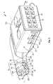
Fig. 1 shows an embodiment of an electrical connector according to the invention in a view from a rear perspective, with an electromagnetic shield according to the invention, and -
Fig. 2 is a view from a front perspective of the electrical connector according to the invention fromFig 1 . - The invention is explained in greater detail below with reference to a 10-pin electrical 90° elbow plug connector with an electromagnetic shield according to the invention shown in the drawing, for the automotive industry. The invention is not to be limited to such a plug connector, however, but to be applicable to all electrical connectors that have a shield. Furthermore, it is not necessary according to the invention that the shield of the electrical connector is an external shield, as shown in the drawing; on the contrary, it is possible according to the invention for the shield to be arranged inside a housing of an electrical connector.
-
Figs. 1 and2 show an embodiment of an electrical connector 1 according to the invention with anelectromagnetic shield 20 according to the invention, which connector can be formed for example as a cable to cable pin connector 1 or socket connector 1. The electrical connector 1 comprises aconnector body 30, which is substantially completely surrounded outside by the two-part shield 20 apart from anend face 32 accessible for electrical contacts. Theshield 20 has twoshield parts shield plates shield plate halves - The two
shield parts mechanical connection 40, preferably acatch mechanism 40, and in the fixed state in relation to one another have substantially the form of a rectangular parallelepiped in the region of the actual electrical connector 1. Thecatch mechanism 40 is configured in such a way that theshield part 100 has catchingrecesses 140 and theshield part 200catching projections 240 corresponding thereto. Both thecatching recesses 140 and thecatching projections 240 can be provided in/on flaps protruding from therespective shield part - Starting out at a 90° angle from the parallelpiped region of the electrical connector 1, the
electromagnetic shield 20 has acrimp portion 22 composed of the twoshield parts crimp portion 22 passing into the parallelepiped region of theshield 20 has in this case substantially the form of a hollow cylinder closed in the circumferential direction U with a substantially circular or elliptical cross-section. A longitudinal direction L of thecrimp portion 22 lies substantially perpendicular to a plug-in direction S of the electrical connector 1. - The
crimp portion 22 of the electrical connector 1 and theelectromagnetic shield 20 is composed of two substantially half-hollow-cylindrical crimp subportions shield parts crimp subportions edges 26. It is naturally possible according to the invention that the twocrimp subportions crimp portion 22 not only from twocrimp subportions shield parts - The electric cable can be fixed on the
crimp portion 22 of the electrical connector 1 by a longitudinal end section. To do this, the longitudinal end section of the cable, stripped up to a braid or a shield, is positioned on/in thecrimp portion 22 in such a way that on the one hand the braid comes to lie externally on thecrimp portion 22 in circumferential direction U and the electric leads of the cable are arranged inside thecrimp portion 22. A crimp barrel, likewise not shown in the drawing, is pushed over the braid and thecrimp portion 22, which barrel is pressed together by means of a crimping tool in a radial direction R of thecrimp portion 22 such that the braid, thecrimp portion 22 and the electric leads of the cable are fixed on one another by the crimp barrel. The plastically deformed crimp barrel holds this combination in a fixed state in relation to one another. - To prevent the braid of the electric cable lying outside on the
crimp portion 22 from penetrating inwards into thecrimp portion 22 due to thecrimp subportions edges 26, the crimp portion has a configuration according to the invention. According to the invention at least oneregion 122 of oneshield part 100 and oneregion 222 of theother shield part 200 overlap in one section and on an abuttingedge 26 in a so-calledoverlap portion 24, which extends at least partly in the circumferential direction U of thecrimp portion 22. Preferably at least onesuch overlap portion 24 is provided for each abuttingedge 26. - Due to this, an evading movement of one
crimp subportion other crimp subportion edge 26, at least in a radial direction R of thecrimp portion 22. In this regard too strong a deformation of thecrimp portion 22 is averted, and due to the overlapping of the tworegions crimp portion 22 and possibly cause electrical short circuits. - According to the invention there is now a plurality of possibilities for configuring an
individual overlap portion 24 on the one hand and on the other hand for providing combinations thereof or respectively an individual section on a single abutting edge or a plurality of abuttingedges 26. Thusindividual overlap portions 24 are possible, which facilitate a movement restriction in only one (seeFigs. 1 and2 ) or in both radial directions R (shown dashed infigure 1 ) of thecrimp portion 22. According to the invention, it is important that the tworegions shield parts - Furthermore, a plurality of embodiments are possible to configure those two
regions single overlap portion 24 of the twocrimp subportions positioning projection 122, such as for example atooth 122, apeg 122 or alug 122, and for the other region 222 apositioning recess 222, such as for example a pocket 222 (open or closed in the radial direction R), aseam 222 or animpression 222 is applicable. In this case thepositioning recess 222 can also be dispensed with, which can depend on the crimping tool used. - One such embodiment is shown explicitly in the drawing (
Figs. 1 and2 ), a second one is shown dashed (onlyFig. 1 ) and a third is shown dotted (likewise onlyFig. 1 ). In all three cases theregions projections 122 andpositioning recesses 222 corresponding to one another, which preferably extend in the circumferential direction U of thecrimp portion 22. - In cases one and two the
positioning projections 122 and the positioning recesses 222 are configured in a tooth-like manner, wherein the positioning recesses 222 are configured somewhat larger in the relevant dimensions than thepositioning projections 122. Furthermore, both preferably have an undercut-free profile in radial direction R, can therefore be fitted into or onto one another without any problem. In the third case, thepositioning recess 222 is instead anextended seam 50. The invention is hereby easily applicable to existingshield parts 200. - In the explicitly shown embodiment, the
shield part 100 has twopositioning projections 122 on itscrimp subportion 120 in the region of an abutting edge 26 (Fig. 1 ) and asingle positioning projection 122 in the region of the abuttingedge 26 lying opposite this (Fig. 2 ). Analogous to this theshield part 200 has two positioningrecesses 222 on itscrimp subportion 220 in the region of the first abutting edge 26 (Fig. 1 ) and asingle positioning recess 222 in the region of the second abutting edge 26 (Fig. 2 ). In this case a single positioning recess or a plurality of positioning recesses 222 in radial direction R can beopen pockets 222 or seams 222. - The
respective positioning projections 122 protrude from thecrimp subportion 120 in circumferential direction U, downwards with reference to the drawing, from the respective abuttingedge 26 and extend into the positioning recesses 222, which are open outwards in a radial direction R and closed inwards and which likewise extend in circumferential direction U. Due to this, thecrimp subportion 120 can no longer shift inwards into thecrimp portion 22 with reference to thecrimp subportion 220 in the region of the abutting edges 26. - Another number and/or distribution of these
overlap portions 24 is naturally applicable. Thus it is possible for example depending on a length of thecrimp portion 22 to provide only a single overlap portion or a plurality ofoverlap portions 24 of the twocrimp subportions edge 26. Quite generally the number ofoverlap portions 24 for each abuttingedge 26 is freely selectable. It is also possible according to the invention to close the positioning recesses 222 in both radial directions R and in longitudinal direction L at least partly, so that even a movement of thecrimp subportion 120 outwards in relation to thecrimp subportion 220 is no longer possible. - The latter function is also fulfilled by the embodiment of the invention shown only by dashed lines in
figure 1 . In this case bothshield parts edge 26 at least onepositioning projection 122 and at least onepositioning recess 222 corresponding thereto. The embodiment shown infigure 1 , however, shows on a side lying opposite theend face 32 of the electrical connector 1 twopositioning projections 120 oncrimp subportion 120 and asingle positioning projection 120 on theother crimp subportion 220. In this case thesingle positioning projection 122 is arranged between the twoother positioning projections 122. An region can be formed by analogy on the other abuttingedge 26. - In this embodiment of the invention, all positioning
recesses 222 are accessible from outside (therefore from outside the crimp portion 22) for thepositioning projections 122. This can be configured differently, however. It is thus possible for example to arrange only a single positioning projection or a plurality or all positioningprojections 122 and their corresponding positioning recesses 222 in such a way that thepositioning projections 122 can engage in the relevant positioning recesses 222 inside thecrimp portion 22. - It is naturally possible according to the invention to arrange differently configured
overlap portions 24 between the twocrimp subportions crimp subportions crimp portion 22 on an abuttingedge 26. In this case acrimp subportion other crimp subportion crimp subportions - When using a
lug 122 as apositioning projection 122 in particular, it is possible to omit thepositioning recess 222; i.e. thelug 122 concerned simply rests on thecrimp subportion 220. Furthermore, thepositioning recess 222 in this case can be formed as animpression 122. In addition, to produce thepositioning recess 222, thecrimp subportion 220 can be slotted in circumferential direction U, wherein a circumferential section of thecrimp subportion 220 that has been cut free is then bent radially outwards and thepositioning recess 222 is obtained thus. This is also possible with slots of the crimp subportion in circumferential direction U and longitudinal direction L. - In the explicitly shown embodiment, the two
shield parts shield part 100 that also has the catchingrecesses 140 for thecatch mechanism 40 of the twoshield parts
Claims (12)
- Electromagnetic shield for an electrical connector (1), in particular an electrical plug connector (1), with two shield parts (100, 200) connectable to one another, wherein
in a crimp portion (22) of the electromagnetic shield (20), an region (122) of one shield part (100) and an region (222) of the other shield part (100) overlap in an overlap portion (24). - Electromagnetic shield according to claim 1, wherein the overlap portion (24) of the two regions (122, 222) of the shield parts (100, 200) extends along a portion of a longitudinal direction (L) of the crimp portion (22).
- Electromagnetic shield according to either claim 1 or claim 2, wherein a plurality of overlap portions (24) is provided between the two shield parts (100, 200) and these overlap portions (24) extend along one or more abutting edges (26) of the crimp portion (22).
- Electromagnetic shield according to any one of claims 1 to 3, wherein a plurality of overlap portions (24) is provided between the two shield parts (100, 200) along a single abutting edge (26) of the crimp portion (22).
- Electromagnetic shield according to any one of claims 1 to 4, wherein the overlap portions (24) of the two shield parts (100, 200) are formed in such a way along a single abutting edge (26) that in a radial direction (R) of the crimp portion (22) at least one overlap portion (24) has a differently offset overlap of the two regions (222, 122) than a second overlap portion (24).
- Electromagnetic shield according to any one of claims 1 to 5, wherein the region (122) of one shield part (100) is a positioning projection (122) and the region (222) of the other shield part (200) is a positioning recess (222).
- Electromagnetic shield according to any one of claims 1 to 6, wherein the region (122) or the positioning projection (122) of one shield part (100) is a tooth (122), a peg (122) or a lug (122), and the region (222) or the positioning recess (122) of the other shield part (200) is a pocket (222), a seam (222) or an impression (222).
- Electromagnetic shield according to any one of claims 1 to 7, wherein the region (122) or the positioning projection (122) of one shield part (100) and the region (222) or the positioning recess (122) of the other shield part (200) have shapes corresponding to one another, which have preferably an undercut-free profile.
- Electromagnetic shield according to any one of claims 1 to 8, wherein the region (122) or the positioning projection (122) of one shield part (100) is insertable into or applicable to the region (222) or the positioning recess (122) of the other shield part (200).
- Electromagnetic shield according to any one of claims 1 to 9, wherein the region (122) or the positioning projection (122) of one shield part (100) extends in a circumferential direction (U) of the crimp portion (22) of the electromagnetic shield (20).
- Electrical connector, in particular pin (1) or socket connector (1) for the motor vehicle or consumer goods sector, with an electromagnetic shield (20) according to any one of claims 1 to 9, wherein the electrical connector (1) has at least two, preferably external, shield parts (100, 200).
- Electrical connector according to claim 11, wherein the electrical connector (1) is an electrical elbow connector (1), which has preferably a 45° or a 90° angle.
Applications Claiming Priority (1)
| Application Number | Priority Date | Filing Date | Title |
|---|---|---|---|
| DE200810037030 DE102008037030B3 (en) | 2008-08-08 | 2008-08-08 | Electromagnetic shield for an electrical connector, as well as electrical connector |
Publications (1)
| Publication Number | Publication Date |
|---|---|
| EP2169779A1 true EP2169779A1 (en) | 2010-03-31 |
Family
ID=41262235
Family Applications (1)
| Application Number | Title | Priority Date | Filing Date |
|---|---|---|---|
| EP09167457A Withdrawn EP2169779A1 (en) | 2008-08-08 | 2009-08-07 | Electromagnetic shield for an electrical connector, and an electrical connector |
Country Status (2)
| Country | Link |
|---|---|
| EP (1) | EP2169779A1 (en) |
| DE (1) | DE102008037030B3 (en) |
Families Citing this family (2)
| Publication number | Priority date | Publication date | Assignee | Title |
|---|---|---|---|---|
| US10008810B2 (en) * | 2015-03-13 | 2018-06-26 | Fci Usa Llc | Electrical connector having a shielding member with two halves each with inwardly and outwardly projecting hooks |
| DE102016116937B4 (en) | 2016-09-09 | 2019-10-02 | HARTING Electronics GmbH | shroud |
Citations (5)
| Publication number | Priority date | Publication date | Assignee | Title |
|---|---|---|---|---|
| US4653825A (en) * | 1985-09-06 | 1987-03-31 | Amp Incorporated | Shielded electrical connector assembly |
| US5199903A (en) * | 1991-02-28 | 1993-04-06 | Amp General Patent Counsel | Ferruleless back shell |
| US5725395A (en) * | 1996-08-12 | 1998-03-10 | Lee; Su-Lan Yang | Universal serial bus connector |
| US20030104727A1 (en) * | 2001-12-03 | 2003-06-05 | Li-Sen Chen | Rear-end electromagnetic shielding component of an electronic connector |
| US20030139095A1 (en) * | 2002-01-22 | 2003-07-24 | Su-Lan Yang Lee | Connector |
Family Cites Families (4)
| Publication number | Priority date | Publication date | Assignee | Title |
|---|---|---|---|---|
| US5895291A (en) * | 1995-11-02 | 1999-04-20 | The Whitaker Corporation | Shielded cable connector assembly |
| US5980320A (en) * | 1997-09-19 | 1999-11-09 | The Whitaker Corporation | Electrical connector having crimped ground shield |
| DE102006012194A1 (en) * | 2006-03-16 | 2007-09-20 | Escha Bauelemente Gmbh | Shielded plug e.g. angular plug, connector for use in e.g. automation engineering, has shield designed in fastening area for mesh wire shield such that shield is arranged for mounting around wire fastened at contact unit of insert |
| DE102006018538B4 (en) * | 2006-04-21 | 2009-09-24 | Tyco Electronics Amp Gmbh | Vehicle data connection |
-
2008
- 2008-08-08 DE DE200810037030 patent/DE102008037030B3/en not_active Expired - Fee Related
-
2009
- 2009-08-07 EP EP09167457A patent/EP2169779A1/en not_active Withdrawn
Patent Citations (5)
| Publication number | Priority date | Publication date | Assignee | Title |
|---|---|---|---|---|
| US4653825A (en) * | 1985-09-06 | 1987-03-31 | Amp Incorporated | Shielded electrical connector assembly |
| US5199903A (en) * | 1991-02-28 | 1993-04-06 | Amp General Patent Counsel | Ferruleless back shell |
| US5725395A (en) * | 1996-08-12 | 1998-03-10 | Lee; Su-Lan Yang | Universal serial bus connector |
| US20030104727A1 (en) * | 2001-12-03 | 2003-06-05 | Li-Sen Chen | Rear-end electromagnetic shielding component of an electronic connector |
| US20030139095A1 (en) * | 2002-01-22 | 2003-07-24 | Su-Lan Yang Lee | Connector |
Also Published As
| Publication number | Publication date |
|---|---|
| DE102008037030B3 (en) | 2010-02-04 |
Similar Documents
| Publication | Publication Date | Title |
|---|---|---|
| EP2642598B1 (en) | Electric terminal | |
| US8690607B2 (en) | Joint connector | |
| EP2346120B1 (en) | Shield connector and production method thereof | |
| JP7118675B2 (en) | Methods for making contact carriers, electrical contact units and ready-made cables | |
| US9722348B2 (en) | System having a plurality of plug-in connectors and multiple plug-in connector | |
| US9379475B2 (en) | Electric connector | |
| US11411352B2 (en) | Connector for automotive applications | |
| US20210057853A1 (en) | Electrical connector and connector assembly | |
| JP2014513391A (en) | Prior ground connection by spring member | |
| JP2018206766A (en) | Contact housing, contact housing receptacle, and electrical connector | |
| US20210057854A1 (en) | Assembly comprising a connector and a cable | |
| US8628354B2 (en) | Adapter element for serial data transfer in a vehicle | |
| EP2169779A1 (en) | Electromagnetic shield for an electrical connector, and an electrical connector | |
| CN112421310B (en) | Connector for automotive applications and method of assembling same | |
| US9419379B2 (en) | Connector having a recessed concave section in a surface between a pair or partition walls between adjacent terminals | |
| JP2010040366A (en) | Connector | |
| EP3783754A1 (en) | Connector for automotive applications | |
| WO2020121926A1 (en) | Harness component | |
| JP7139929B2 (en) | harness parts | |
| EP2696444B1 (en) | Joint connector | |
| JP6241754B2 (en) | Manufacturing method of joint connector | |
| KR20140063793A (en) | Connector unit comprising a second connector including a spacer for locking a second terminal | |
| JP2010118150A (en) | Connector | |
| US20230198187A1 (en) | Electrical Plug Connector and Method for Assembling an Electrical Plug Connector | |
| CN108023194B (en) | Conductive terminal and connector |
Legal Events
| Date | Code | Title | Description |
|---|---|---|---|
| PUAI | Public reference made under article 153(3) epc to a published international application that has entered the european phase |
Free format text: ORIGINAL CODE: 0009012 |
|
| AK | Designated contracting states |
Kind code of ref document: A1 Designated state(s): AT BE BG CH CY CZ DE DK EE ES FI FR GB GR HR HU IE IS IT LI LT LU LV MC MK MT NL NO PL PT RO SE SI SK SM TR |
|
| AX | Request for extension of the european patent |
Extension state: AL BA RS |
|
| STAA | Information on the status of an ep patent application or granted ep patent |
Free format text: STATUS: THE APPLICATION IS DEEMED TO BE WITHDRAWN |
|
| 18D | Application deemed to be withdrawn |
Effective date: 20101001 |