EP2169345B1 - Blade tip clearance measurement sensor - Google Patents
Blade tip clearance measurement sensor Download PDFInfo
- Publication number
- EP2169345B1 EP2169345B1 EP09010615.4A EP09010615A EP2169345B1 EP 2169345 B1 EP2169345 B1 EP 2169345B1 EP 09010615 A EP09010615 A EP 09010615A EP 2169345 B1 EP2169345 B1 EP 2169345B1
- Authority
- EP
- European Patent Office
- Prior art keywords
- sensor assembly
- electromagnetic field
- recited
- ceramic
- coil
- Prior art date
- Legal status (The legal status is an assumption and is not a legal conclusion. Google has not performed a legal analysis and makes no representation as to the accuracy of the status listed.)
- Active
Links
Images

Classifications
-
- G—PHYSICS
- G01—MEASURING; TESTING
- G01B—MEASURING LENGTH, THICKNESS OR SIMILAR LINEAR DIMENSIONS; MEASURING ANGLES; MEASURING AREAS; MEASURING IRREGULARITIES OF SURFACES OR CONTOURS
- G01B7/00—Measuring arrangements characterised by the use of electric or magnetic techniques
- G01B7/14—Measuring arrangements characterised by the use of electric or magnetic techniques for measuring distance or clearance between spaced objects or spaced apertures
-
- F—MECHANICAL ENGINEERING; LIGHTING; HEATING; WEAPONS; BLASTING
- F01—MACHINES OR ENGINES IN GENERAL; ENGINE PLANTS IN GENERAL; STEAM ENGINES
- F01D—NON-POSITIVE DISPLACEMENT MACHINES OR ENGINES, e.g. STEAM TURBINES
- F01D11/00—Preventing or minimising internal leakage of working-fluid, e.g. between stages
- F01D11/08—Preventing or minimising internal leakage of working-fluid, e.g. between stages for sealing space between rotor blade tips and stator
- F01D11/14—Adjusting or regulating tip-clearance, i.e. distance between rotor-blade tips and stator casing
- F01D11/20—Actively adjusting tip-clearance
-
- F—MECHANICAL ENGINEERING; LIGHTING; HEATING; WEAPONS; BLASTING
- F01—MACHINES OR ENGINES IN GENERAL; ENGINE PLANTS IN GENERAL; STEAM ENGINES
- F01D—NON-POSITIVE DISPLACEMENT MACHINES OR ENGINES, e.g. STEAM TURBINES
- F01D21/00—Shutting-down of machines or engines, e.g. in emergency; Regulating, controlling, or safety means not otherwise provided for
- F01D21/003—Arrangements for testing or measuring
-
- F—MECHANICAL ENGINEERING; LIGHTING; HEATING; WEAPONS; BLASTING
- F05—INDEXING SCHEMES RELATING TO ENGINES OR PUMPS IN VARIOUS SUBCLASSES OF CLASSES F01-F04
- F05D—INDEXING SCHEME FOR ASPECTS RELATING TO NON-POSITIVE-DISPLACEMENT MACHINES OR ENGINES, GAS-TURBINES OR JET-PROPULSION PLANTS
- F05D2270/00—Control
- F05D2270/30—Control parameters, e.g. input parameters
- F05D2270/305—Tolerances
Definitions
- the subject invention is directed to electromagnetic field sensors, and more particularly, to a blade tip measurement system that uses a marginal oscillator circuit and a heat resistant sensor assembly to generate an RF electromagnetic field in a casing of a gas turbine engine, whereby perturbation of the field by an array of rotating blade tips represents a change in susceptibility that impacts the circuit to indicate a clearance measurement between the blade tips and the engine casing.
- the prior art includes a variety of solutions for maintaining blade tip clearance in a gas turbine engine.
- One such solution is a mechanical system for adjusting the radial position of the casing surrounding the rotor blades to improve engine efficiency, as disclosed in U.S. Patent No. 5,104,287 .
- Another solution is a mechanical system for moving the rotor disc relative to the engine casing, as disclosed for example in U.S. Patent No. 5,330,320 .
- An active clearance control systems that includes an actuator for moving a rotor blade assembly relative to the engine casing to maintain the minimum design clearance between the blade tips and the engine casing is disclosed in U.S. Patent No. 7,407,369 .
- These clearance control systems require a mechanism for monitoring blade tip clearance with a high degree of accuracy, under the severe environmental conditions that exist within the turbine gas path. These severe conditions include high blade tip speeds, vibration modes, high pressure fluctuations and the exceedingly high temperatures of the turbine gases, which can be as hot as 1400 °C.
- optical measuring devices known in the art are effective for measuring blade tip clearance, they are often susceptible to the severe thermal environment of a gas turbine engine, leading to difficulties in calibration, which can result in inaccurate measurements over time.
- US 4,563,643 discloses an eddy-current sensor having a thimble shaped alumina housing into which are positioned first and second coils wound about an insulating plastic (polyimide) coil support.
- a Kovar sealing ring seals the alumina housing to a metallic base member to which is secured a protective tube carrying an electrical cable which makes electrical connection with the coils.
- a multifaceted nut secured to the metallic shielding of the cable nestles within a complementary shaped insulating member to prevent the cable from being twisted or withdrawn from the sensor thus maintaining electrical integrity.
- US 4,267,508 discloses an apparatus for non-contact measurement of the distance or gap between a detection coil and a metallic body arranged in an opposing relation with the detection coil, includes a differential amplifier having one input terminal connected to a reference oscillator and the other input terminal connected to a feedback circuit.
- the detection coil comprises a cylindrical coil and a plurality of magnetic members in rod form is arranged inside its inner bore along the direction of the coil axis and adjacent to the coil inner wall.
- the apparatus has an increased measuring span, wherein the accuracy of the measurement is not changed by any temperature change.
- US 4,311,982 teaches a transducer for measuring temperature by means of the temperature-induced resistance change.
- the transducer comprises wire coil and a cylindrical ceramic mandrel on which the coil is wound.
- the transducer maintains the desired precision, repeatability and stability of a wirewound transducer while at the same time being capable of calibration by trimming techniques commonly used for adjusting film resistors.
- GB 765,546 discloses an inductance coil arrangement having its self-capacity determined by one or more dielectric bodies arranged in the electric field of the coil, the bodies serving to give a desired temperature coefficient of the impedance of the coil is characterized in that the dielectric bodies are independent of the supporting means for the coil and do not affect the geometric dimension of the coil.
- the coil is supported on a base by means of terminals and the temperature coefficient of the bodies may be equal and opposite to the temperature coefficient of the coil such that the resonant frequency of the coil remains constant. With such constructions the temperature characteristic may be varied after manufacture.
- US 4 517 156 A discloses an electrical resistant alloy for use in a sensing coil.
- US 5 126 664 A discloses a small diameter proximity coil for use in proximity sensors.
- US 2005/218887 A1 discloses a measurement device for measuring the wear of turbo-machine components.
- the subject invention is directed to an electromagnetic field sensor assembly, and more particularly, to a sensor assembly and system for monitoring or otherwise measuring blade tip clearance in a gas turbine engine.
- the sensor assembly is particularly well adapted for the high temperature operating environment that exists within a gas turbine engine.
- the sensor assembly includes a ceramic sensor body; a wire coil wound about a distal end portion of the ceramic sensor body for producing an electromagnetic field, wherein the wire coil is formed from a platinum group metal or an alloy thereof; a ceramic well enclosing the ceramic sensor body and the wire coil; and a metallic housing surrounding a periphery of the ceramic well and having an open distal end; characterized in that the metallic housing includes an increased inner diameter at the open distal end forming an annular recess between the distal end of the metallic housing and a distal portion of the ceramic well, the annular recess and open distal end thereby being dimensioned to reduce the influence of the metallic housing on the electromagnetic field.
- the outer housing of the sensor assembly is configured to be mounted in the engine casing adjacent an array of blade tips.
- the sensor body is preferably formed from aluminum oxide or a similar refractory material.
- the wire coil wrapped about the distal end portion of the sensor body is preferably formed from wire comprised of a platinum group metal or an alloy thereof.
- the wire may be formed from Pt-10Rh, which is a platinum alloy that includes 10% Rhodium.
- the wire may be formed from an oxide dispersion strengthened platinum group metal or alloy thereof.
- the coil is formed from ceramic coated wire, and more preferably, the wire forming the coil is coated with aluminum oxide.
- the coil is preferably formed in plural layers, with each layer having a plurality of turns.
- the distal end portion of the sensor body has an annular recess for accommodating the multi-layered coil, and the coil is anchored to the sensor body within the annular recess by cement.
- the ceramic well is a sealed enclosure and is preferably formed from aluminum oxide, and it has a metallized section to facilitate attachment to the metallic outer housing.
- the metallic outer housing is formed from a heat resistant metal that is compatible with the material from which the adjacent engine casing is constructed, such as, for example, Ni-Cr alloy 600. It is envisioned that the outer housing may include a plurality of longitudinally extending cooling channels communicating with the exterior of the engine casing.
- a transition member is provided for joining the ceramic well to the metal housing, while serving to buffer thermal stress in the sensor assembly.
- a cable adapter is also joined to the metallic housing adjacent the proximal end portion thereof, and a pair of coaxial cable assemblies are joined to the cable adapter for connection with the coil of the sensor body. More particularly, cable lead wires join the center conductors of the coaxial cables to opposed ends of the coil.
- the center conductor of each coaxial cable is formed from two different materials including a first temperature resistant material located adjacent to the sensor assembly and a second material located remote from the sensor assembly in a region of lower temperature.
- the sensor assembly includes two sensor bodies each having a multi-layered coil associated with the distal end portion thereof, wherein each coil is driven by or otherwise forms part of a separate marginal oscillator circuit.
- the distal end portions of the two sensor bodies are axially off-set from one another to facilitate system level self-calibration.
- the subject invention is also directed to a blade tip clearance measurement system for a gas turbine engine that includes an electromagnetic field sensor assembly positioned in the casing of a gas turbine engine adjacent an array of blade tips, a marginal oscillator circuit operatively connected to the sensor assembly for generating an electromagnetic field in relation to the blade tips, and means for processing an output signal received from the sensor assembly in response to perturbation of the electromagnetic field by passage of the blade tips therethrough, wherein the output signal is indicative of the position of the blade tips relative to the engine casing.
- the coil wire that is positioned within the temperature resistant sensor assembly is a remote extension of the marginal oscillator circuit.
- the subject invention is further directed to a method for measuring blade tip clearance in a gas turbine engine that includes the steps of generating an electromagnetic field between the engine casing and an array of rotating blade tips, sensing changes in the electromagnetic field as the rotating blade tips pass therethrough, and determining the position of the blade tips relative to the engine casing based upon changes in the electromagnetic field.
- FIG. 1 there is illustrated a blade tip clearance measurement sensor assembly constructed in accordance with a preferred embodiment of the subject invention and designated generally by reference numeral 10.
- sensor assembly 10 is mounted in the casing 12 of a gas turbine engine adjacent to a blade tip 14 of a turbine blade 16. While not shown, those having ordinary skill in the art will readily appreciate that an array of turbine blades 16 are mounted on a rotating disc within the engine casing 12.
- Sensor assembly 10 employs a RF electromagnetic field to measure or otherwise monitor the clearance that exists between the blade tips 14 and the engine casing 12, with a high degree of accuracy. As explained in more detail below, sensor assembly 10 is constructed in such a manner so as to withstand the severe environmental and operational conditions that exist in and adjacent to the turbine gas path, where operating temperatures often reach as high as 1400 °C.
- the sensor assembly 10 is operatively associated with a marginal oscillator circuit 20.
- the marginal oscillator circuit 20 is designed to generate a RF electromagnetic field for measuring blade tip clearance, in near real time.
- An example of such a circuit is disclosed in U.S. Patent No. 6,984,994 .
- perturbation of the RF electromagnetic field by the blade tips 14 moving therethrough represents a change in susceptibility that impacts the marginal oscillator circuit 20, providing a signal indicative of the position of the blade tips 14 relative to the engine casing 12.
- the storage of energy by the field gives rise to a change in frequency (FM)
- a loss of energy from the field gives rise to a change in its amplitude (AM).
- FM change in frequency
- AM amplitude
- Both of these signatures are part of the output signal data stream.
- the sensor assembly 10 supports two simultaneous data streams relating to blade tip clearance, including one data stream that is related to oscillator frequency and one data stream that is related to oscillator amplitude.
- a signal processing circuit 22 conditions the output signal from the sensor assembly 10 and oscillator 20 to provide an output measurement of the blade tip clearance that is readily interpreted by those having ordinary skill in the art. Moreover, the output signal from the sensor assembly 10 and oscillator 20 is conditioned by the signal processor 22 in such a manner so as to provide an indication of the gap distance that exists between the rotating blade tips 14 and the engine casing 12, as shown for example in Fig. 5 .
- the sensor assembly 10 of the subject invention includes a cylindrical outer housing 24 that is adapted and configured to mount to the casing 12 of a gas turbine engine, as shown in Figs. 1 and 5 .
- the outer housing 24 is formed form a heat resistant metal that is preferably compatible with the material from which the surrounding engine casing is constructed, such as, for example, Ni-Cr alloy 600 or a similar material.
- the outer housing 24 of sensor assembly 10 has an open distal end, as shown in Fig. 2 , and a proximal mounting flange 26 dimensioned to be positioned against the exterior surface of the engine casing 12.
- the open distal end of the outer housing 24 is slightly recessed from the interior surface of the engine casing 12, to protect the sensor assembly 10 from damage during engine operation. Because of this special accommodation, the tip clearance sensing system must be calibrated by correcting the output signal from the sensor assembly to account for the additional distance between the engine casing 12 and the electromagnetic field sensing element.
- a plurality of circumferentially spaced apart, longitudinally extending cooling channels 28 are formed in the exterior surface of outer housing 24.
- the cooling channels 28 direct cool air toward the distal sensor head located within the engine casing as a result of the pressure differential that exists between the exterior of the engine casing where the flange 26 is located and the interior of the engine casing where the distal sensing head of the sensor assembly is located.
- these cooling channels would only be effective in engine applications where the hot side of the engine casing is at a lower pressure than the cool side of the engine casing. In engine applications where this pressure differential is not present, the cooling channels in the outer housing can be eliminated.
- the sensor assembly 10 further includes a cylindrical ceramic well 30, which contains or otherwise encloses the internal sensor components, as described in more detail below with respect to Figs. 3 and 4 .
- Sensor assembly 10 also includes a metal cable adapter 32 having a flange 25 that is welded to the mounting flange 26 at proximal end of the outer housing 24. Cable adapter 32 facilitates the connection of a pair of metal-sheathed coaxial cables 34 and 36 with the sensor assembly 10.
- the metal sheathed coaxial cables 34 and 36 are attached to the metal cable adapter 32 by brazing or a similar mechanical joining technique.
- Coaxial cables 34 and 36 operatively connect the sensor assembly 10 to the marginal oscillator circuit 20 and the signal processing circuit 22, respectively.
- the coaxial cables 34 and 36 are low-loss ceramic insulated, metal sheathed, RF cables (e.g., silicon oxide insulated RF cables or the like) that are adapted to minimize high frequency losses.
- signals are transmitted to and from sensor assembly 10 by way of the center conductors of coaxial cables 34 and 36.
- the outer conductors provide dielectric shielding for the center conductors and form part of the hermetically sealed closure which defines the sensor assembly 10.
- the ceramic well 30 of sensor assembly 10 is formed from aluminum oxide and is secured to the outer housing 24 by a metallic transition ring 38. More particularly, a metallized coating indicated by reference numeral 35, is applied to the proximal end portion of the ceramic well 30.
- a suitable metallized coating consists of a molybdenum manganese film with nickel plating.
- the transition ring 38 is preferably formed from Pt-10Rh and serves to buffer thermal stress between the ceramic well 30 and the outer metal housing 24.
- sensor assembly 10 further includes a cylindrical sensor body 40 or former supported within the ceramic well 30.
- Sensor body 40 is formed from a ceramic material, such as for example, aluminum oxide or a similar refractory material.
- An annular recess 42 is formed in the distal end portion of the sensor body for accommodating a wound wire coil 44.
- Wire coil 44 serves as the functional sensing element of sensor assembly 10 by producing the RF electromagnetic field generated by the marginal oscillator circuit 20 to measure the clearance between the engine casing 12 and blade tips 14, as shown for example in Fig. 5 .
- the wire coil 44 is a remote extension of the marginal oscillator circuit 20 located adjacent to the target or object that is to be sensed, namely, the blade tips 14.
- the distal end portion of the sensor assembly 10, and hence the coil wire 44 is recessed into the engine casing wall to protect the sensor assembly 10 during engine operation. Since the distance between the coil 44 and engine casing 12 is a fixed distance, the output signal from the coil 44 can be corrected as part of the system calibration to provide the requisite clearance distance between the engine casing 12 and the blade tips 14.
- the coil 44 is formed from a heat resistant wire comprised of a platinum group metal or alloy thereof, such as, for example, Pt-10Rh, which is a platinum alloy that includes 10% Rhodium.
- the wire of coil 44 is of relatively small gauge, such as, for example 0.003 inches, and is preferably coated with ceramic, for example, aluminum oxide to provide electrical insulation for the densely packed, multi-layered construction of wire coil 44.
- the coil 44 is formed in plural winding layers, with each winding layer having multiple turns.
- the radially inner wound layer has 8 turns
- the middle wound layer has 7 turns
- the radially outer wound layer has six turns.
- the coil 44 is coated with cement (e.g. aluminum oxide and colloidal silica) to anchor the wires to the sensor body 40.
- the sensor body 40 also includes diametrically opposed lateral channels 46 and 48 for respectively accommodating the lead wires 34a and 36a that extend from the two coaxial cable 34 and 36.
- the lead wires 34a and 36a are fused to the center conductors of the coaxial cable 34 and 36.
- the lead wires 34a and 36a are also connected to the opposite ends of wire coil 44, within in diametrically opposed molded recesses 50, one of which is shown for example in Fig. 4 .
- the lead wires 34a and 36a are fed from the respective lateral channels 46 and 48, though internal passages formed within the ceramic sensor body 40, and out to the opposed molded recesses 50 where they join the opposed ends of wire coil 44.
- the lead wires 34a and 36a are attached to the opposed ends of the wire coil 44 by a mechanical crimp or fuse joint or by similar mechanical means.
- the lead wires 34a and 36a are formed from Pt-10Rh.
- the lead wires 34a and 36a and the wire coil 44 can be made from an oxide dispersion strengthened platinum group metal or alloy thereof to enhance the high temperature reliability of the sensor assembly 10.
- This material is produced with fine ceramic particles, such as zirconia or yittria, dispersed throughout the metal, that serve to stabilize the grain structure when used at high temperatures. In the field of thermometry, it is known to improve the durability of sensor components in this manner.
- An example of heat resistant wires for use in temperature sensing is disclosed in U.S. Patent No 7,026,908 .
- the proximal end portions of lead wires 34a and 36a of cable adapter 32 which are located within the interior cavity 45, are bent at a right angle.
- This structural geometry provides a means of thermal strain relief in the lead wires to ensure that a reliable mechanical connection is maintained between the lead wires and the opposed ends of coil wire 44.
- the ceramic sensor body 40 is mounted in or otherwise molded into place within the ceramic well 30 of sensor assembly 10 by a ceramic-based potting material 60.
- the potting material 60 ensures that the sensor body 40 is securely positioned within the well 30 so that the location of the coil 44 is rigidly maintained.
- the ceramic well and ceramic sensor body of sensor assembly 10 could be formed as a unitary ceramic component, rather than two separate elements that are joined together to form an integral structure.
- a platinum group metal or alloy thereof for forming the lead wires and wire coil is particularly advantageous during fabrication of the sensor assembly, since that material can withstand the sintering temperatures that are required to fabricate a unitary ceramic component.
- the inner diameter of the metal outer housing 24 has a reduced inner diameter, forming an annular recess 55 that surrounds the distal portion of the ceramic well 30, in the region of coil 44. This is done to minimize the influence of the metal housing 24 on the electromagnetic field produced the coil 44.
- a cover 64 is provided at the proximal end of cable adapter 32 to enclose and seal the interior cavity 45 thereof.
- the interior cavity 45 of the cable adapter 32 is filled with a ceramic powder or felt, as shown for example in Fig. 6 .
- the cover 64 is welded onto the adapter 32.
- an inert gas is introduced into the cavity 35 through a port 66 in the cover 64.
- the port 66 is then closed with a welded plug 68.
- the ceramic powder or felt provide mechanical support for the cable lead wires 34a and 36a, while the inert gas serves to protect the cable lead wires 34a and 36a from oxidation.
- each coaxial cable 34, 36 would be formed from two different conductors 72, 74, consisting of two different materials, materials joined together in series at a junction point 75.
- the two conductor materials forming the center conductor of the coaxial cables would include a first temperature resistant conductor material, such as Pt-10Rh or a similar platinum based alloy, located in a region "a" of relatively high adjacent (e.g., 900° C) to the sensor assembly 10 and a second conductor material, such as copper, located in a region "b" of relatively lower temperature (e.g., 250° C) remote from the sensor assembly 10.
- This serial conductor configuration would eliminate the need for backfilling the interior cavity 45 of cable adapter cavity 32 with a protective inert gas.
- the coil 44 at the distal end of sensor body 40 produces a RF electromagnetic field, which is generated by the marginal oscillator circuit 20.
- the sensor assembly 10 detects changes in the electromagnetic field as the rotating blade tips 14 pass therethrough.
- the signal processing circuit 22 determines the position of the blade tips 14 relative to the engine casing 12 based upon changes in the electromagnetic field produced by the coil 44. Using that information, adjustments can be made to the rotor disc and/or engine casing, to minimize the clearance between the blade tips and engine casing, and thus improve engine efficiency.
- Sensor assembly 100 includes two sensor bodies 140a and 140b mounted side-by-side within a single ceramic well 130 having parallel well chambers 130a, 103b.
- the ceramic well 130 is enclosed within a metal outer housing 124, with each sensor body 140a, 140b having a separate wire coil 144a, 144b for producing an independent electromagnetic field. That is, each coil is driven by or otherwise a remote part of a separate marginal oscillator circuit.
- the distal end portions of the sensor bodies 140a, 140b and thus the coils 144a and 144b associated therewith are axially off-set from one another.
- one coil may be axially displaced from the other coil by about 0.5 mm.
- each coil will produce a different voltage and frequency response as the blade tip passes through the electromagnetic field. This dual coil arrangement will facilitate system level self-calibration of the sensor system.
Landscapes
- Engineering & Computer Science (AREA)
- Mechanical Engineering (AREA)
- General Engineering & Computer Science (AREA)
- Physics & Mathematics (AREA)
- General Physics & Mathematics (AREA)
- Measurement Of Length, Angles, Or The Like Using Electric Or Magnetic Means (AREA)
Description
- The subject invention is directed to electromagnetic field sensors, and more particularly, to a blade tip measurement system that uses a marginal oscillator circuit and a heat resistant sensor assembly to generate an RF electromagnetic field in a casing of a gas turbine engine, whereby perturbation of the field by an array of rotating blade tips represents a change in susceptibility that impacts the circuit to indicate a clearance measurement between the blade tips and the engine casing.
- In an axial flow gas turbine engine, it is desirable to minimize the clearance between the blade tips of a turbine rotor and the engine casing that surrounds the rotor. This is because excessive clearances between the blade tips and the engine casing reduce engine efficiency, and contact between the blade tips and engine casing causes damage to the engine.
- The prior art includes a variety of solutions for maintaining blade tip clearance in a gas turbine engine. One such solution is a mechanical system for adjusting the radial position of the casing surrounding the rotor blades to improve engine efficiency, as disclosed in
U.S. Patent No. 5,104,287 . Another solution is a mechanical system for moving the rotor disc relative to the engine casing, as disclosed for example inU.S. Patent No. 5,330,320 . An active clearance control systems that includes an actuator for moving a rotor blade assembly relative to the engine casing to maintain the minimum design clearance between the blade tips and the engine casing is disclosed inU.S. Patent No. 7,407,369 . - These clearance control systems require a mechanism for monitoring blade tip clearance with a high degree of accuracy, under the severe environmental conditions that exist within the turbine gas path. These severe conditions include high blade tip speeds, vibration modes, high pressure fluctuations and the exceedingly high temperatures of the turbine gases, which can be as hot as 1400 °C.
- An example of a prior art blade tip clearance monitoring system is disclosed in
U.S. Patent No. 6,678,060 to Hayworth , which employs a group of photo-cells that monitor the position of the blade tips by detecting changes in the shape of a detected image. Another example of a prior art blade tip monitoring system is disclosed inU.S. Patent No. 5,739,524 to Fally , which employs an optical probe that senses the distance of an object by measuring reflected radiation. - While optical measuring devices known in the art are effective for measuring blade tip clearance, they are often susceptible to the severe thermal environment of a gas turbine engine, leading to difficulties in calibration, which can result in inaccurate measurements over time.
-
US 4,563,643 discloses an eddy-current sensor having a thimble shaped alumina housing into which are positioned first and second coils wound about an insulating plastic (polyimide) coil support. A Kovar sealing ring seals the alumina housing to a metallic base member to which is secured a protective tube carrying an electrical cable which makes electrical connection with the coils. A multifaceted nut secured to the metallic shielding of the cable nestles within a complementary shaped insulating member to prevent the cable from being twisted or withdrawn from the sensor thus maintaining electrical integrity. -
US 4,267,508 discloses an apparatus for non-contact measurement of the distance or gap between a detection coil and a metallic body arranged in an opposing relation with the detection coil, includes a differential amplifier having one input terminal connected to a reference oscillator and the other input terminal connected to a feedback circuit. The detection coil comprises a cylindrical coil and a plurality of magnetic members in rod form is arranged inside its inner bore along the direction of the coil axis and adjacent to the coil inner wall. The apparatus has an increased measuring span, wherein the accuracy of the measurement is not changed by any temperature change. -
US 4,311,982 teaches a transducer for measuring temperature by means of the temperature-induced resistance change. The transducer comprises wire coil and a cylindrical ceramic mandrel on which the coil is wound. The transducer maintains the desired precision, repeatability and stability of a wirewound transducer while at the same time being capable of calibration by trimming techniques commonly used for adjusting film resistors. -
GB 765,546 -
US 4 517 156 A discloses an electrical resistant alloy for use in a sensing coil.US 5 126 664 A discloses a small diameter proximity coil for use in proximity sensors.US 2005/218887 A1 discloses a measurement device for measuring the wear of turbo-machine components. - The subject invention is directed to an electromagnetic field sensor assembly, and more particularly, to a sensor assembly and system for monitoring or otherwise measuring blade tip clearance in a gas turbine engine. The sensor assembly is particularly well adapted for the high temperature operating environment that exists within a gas turbine engine. In this regard, the sensor assembly includes a ceramic sensor body; a wire coil wound about a distal end portion of the ceramic sensor body for producing an electromagnetic field, wherein the wire coil is formed from a platinum group metal or an alloy thereof; a ceramic well enclosing the ceramic sensor body and the wire coil; and a metallic housing surrounding a periphery of the ceramic well and having an open distal end; characterized in that the metallic housing includes an increased inner diameter at the open distal end forming an annular recess between the distal end of the metallic housing and a distal portion of the ceramic well, the annular recess and open distal end thereby being dimensioned to reduce the influence of the metallic housing on the electromagnetic field.
- The outer housing of the sensor assembly is configured to be mounted in the engine casing adjacent an array of blade tips.
- The sensor body is preferably formed from aluminum oxide or a similar refractory material. The wire coil wrapped about the distal end portion of the sensor body is preferably formed from wire comprised of a platinum group metal or an alloy thereof. For example, the wire may be formed from Pt-10Rh, which is a platinum alloy that includes 10% Rhodium. Alternatively, the wire may be formed from an oxide dispersion strengthened platinum group metal or alloy thereof. Preferably, the coil is formed from ceramic coated wire, and more preferably, the wire forming the coil is coated with aluminum oxide. The coil is preferably formed in plural layers, with each layer having a plurality of turns. Preferably, the distal end portion of the sensor body has an annular recess for accommodating the multi-layered coil, and the coil is anchored to the sensor body within the annular recess by cement.
- The ceramic well is a sealed enclosure and is preferably formed from aluminum oxide, and it has a metallized section to facilitate attachment to the metallic outer housing. Preferably, the metallic outer housing is formed from a heat resistant metal that is compatible with the material from which the adjacent engine casing is constructed, such as, for example, Ni-Cr alloy 600. It is envisioned that the outer housing may include a plurality of longitudinally extending cooling channels communicating with the exterior of the engine casing.
- Preferably, a transition member is provided for joining the ceramic well to the metal housing, while serving to buffer thermal stress in the sensor assembly. A cable adapter is also joined to the metallic housing adjacent the proximal end portion thereof, and a pair of coaxial cable assemblies are joined to the cable adapter for connection with the coil of the sensor body. More particularly, cable lead wires join the center conductors of the coaxial cables to opposed ends of the coil. In an embodiment of the subject invention, the center conductor of each coaxial cable is formed from two different materials including a first temperature resistant material located adjacent to the sensor assembly and a second material located remote from the sensor assembly in a region of lower temperature.
- In another embodiment of the subject invention, the sensor assembly includes two sensor bodies each having a multi-layered coil associated with the distal end portion thereof, wherein each coil is driven by or otherwise forms part of a separate marginal oscillator circuit. In such an instance, the distal end portions of the two sensor bodies are axially off-set from one another to facilitate system level self-calibration.
- The subject invention is also directed to a blade tip clearance measurement system for a gas turbine engine that includes an electromagnetic field sensor assembly positioned in the casing of a gas turbine engine adjacent an array of blade tips, a marginal oscillator circuit operatively connected to the sensor assembly for generating an electromagnetic field in relation to the blade tips, and means for processing an output signal received from the sensor assembly in response to perturbation of the electromagnetic field by passage of the blade tips therethrough, wherein the output signal is indicative of the position of the blade tips relative to the engine casing. In essence, the coil wire that is positioned within the temperature resistant sensor assembly is a remote extension of the marginal oscillator circuit.
- The subject invention is further directed to a method for measuring blade tip clearance in a gas turbine engine that includes the steps of generating an electromagnetic field between the engine casing and an array of rotating blade tips, sensing changes in the electromagnetic field as the rotating blade tips pass therethrough, and determining the position of the blade tips relative to the engine casing based upon changes in the electromagnetic field.
- These and other features of the blade tip clearance measurement system, sensor assembly and measurement method of the subject invention will become more readily apparent to those having ordinary skill in the art from the following detailed description of the invention taken in conjunction with the several drawings described below.
- So that those skilled in the art to which the subject invention appertains will readily understand how to make and use the blade tip clearance sensor, sensing system and sensing method of the subject invention without undue experimentation, preferred embodiments thereof will be described in detail below with reference to certain figures, wherein:
-
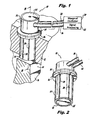
Fig. 1 is a perspective view of an electromagnetic sensor assembly for measuring blade tip clearance in a gas turbine engine, constructed in accordance with a preferred embodiment of the subject invention, wherein the sensor assembly is mounted in the engine casing of a gas turbine engine adjacent the outer periphery of a rotor disc carrying an array of turbine blades, and is operatively associated with a marginal oscillator circuit for generating a RF electromagnetic field and a signal processing circuit for processing output signals from the sensor assembly in response to perturbation of the field by the blade tips during engine operation; -
Fig. 2 is a perspective view of the electromagnetic sensor assembly of the subject invention; -
Fig. 3 is an exploded perspective view of the electromagnetic sensor assembly of shown inFig. 2 , with parts separated for ease of illustration; -
Fig. 4 is an exploded perspective view of the ceramic well and sensor body of the electromagnetic sensor assembly ofFigs. 2 and3 , showing the wound coil in a recess formed at the distal end portion of the ceramic body; -
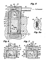
Fig. 5 is cross-sectional view, taken along line 5-5 ofFig. 1 , illustrating the electromagnetic sensor assembly during engine operation, wherein a RF electromagnetic field is generated to measure or otherwise monitor the clearance between engine casing and the blade tips; -
Fig. 5a is a localized view of the distal end portion of the sensor assembly, illustrating the multi-layered wrapping of the coil turns; -
Fig. 6 and 7 are cross-sectional views of the proximal end portion of the sensor assembly of the subject invention, illustrating the steps of filling the sensor cavity with a ceramic powder or felt and then introducing an inert gas into the cavity to protect the cable lead wires from oxidation; -
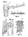
Fig. 8 is a perspective view of the electromagnetic sensor assembly of the subject invention, which employs coaxial conductors that include two different materials to form the center conductors, as shown illustratedFig. 9 ; -
Fig. 10 is and exploded perspective view of another embodiment of the electromagnetic sensor assembly of the subject invention, which includes two sensor bodies; and -
Fig. 11 is a cross-sectional view of the electromagnetic sensor assembly ofFig. 10 , illustrating the axially off-set sensor bodies located within the sensor assembly. - Referring now to
Fig. 1 , there is illustrated a blade tip clearance measurement sensor assembly constructed in accordance with a preferred embodiment of the subject invention and designated generally byreference numeral 10. As illustrated,sensor assembly 10 is mounted in thecasing 12 of a gas turbine engine adjacent to a blade tip 14 of aturbine blade 16. While not shown, those having ordinary skill in the art will readily appreciate that an array ofturbine blades 16 are mounted on a rotating disc within theengine casing 12. -
Sensor assembly 10 employs a RF electromagnetic field to measure or otherwise monitor the clearance that exists between the blade tips 14 and theengine casing 12, with a high degree of accuracy. As explained in more detail below,sensor assembly 10 is constructed in such a manner so as to withstand the severe environmental and operational conditions that exist in and adjacent to the turbine gas path, where operating temperatures often reach as high as 1400 °C. - As shown schematically in
Fig. 1 , thesensor assembly 10 is operatively associated with amarginal oscillator circuit 20. Themarginal oscillator circuit 20 is designed to generate a RF electromagnetic field for measuring blade tip clearance, in near real time. An example of such a circuit is disclosed inU.S. Patent No. 6,984,994 . - During engine operation, perturbation of the RF electromagnetic field by the blade tips 14 moving therethrough represents a change in susceptibility that impacts the
marginal oscillator circuit 20, providing a signal indicative of the position of the blade tips 14 relative to theengine casing 12. In this regard, the storage of energy by the field gives rise to a change in frequency (FM), while a loss of energy from the field gives rise to a change in its amplitude (AM). Both of these signatures are part of the output signal data stream. In other words, thesensor assembly 10 supports two simultaneous data streams relating to blade tip clearance, including one data stream that is related to oscillator frequency and one data stream that is related to oscillator amplitude. - A
signal processing circuit 22 conditions the output signal from thesensor assembly 10 andoscillator 20 to provide an output measurement of the blade tip clearance that is readily interpreted by those having ordinary skill in the art. Moreover, the output signal from thesensor assembly 10 andoscillator 20 is conditioned by thesignal processor 22 in such a manner so as to provide an indication of the gap distance that exists between the rotating blade tips 14 and theengine casing 12, as shown for example inFig. 5 . - Referring now to
Fig. 2 , thesensor assembly 10 of the subject invention includes a cylindricalouter housing 24 that is adapted and configured to mount to thecasing 12 of a gas turbine engine, as shown inFigs. 1 and5 . Theouter housing 24 is formed form a heat resistant metal that is preferably compatible with the material from which the surrounding engine casing is constructed, such as, for example, Ni-Cr alloy 600 or a similar material. Theouter housing 24 ofsensor assembly 10 has an open distal end, as shown inFig. 2 , and a proximal mountingflange 26 dimensioned to be positioned against the exterior surface of theengine casing 12. - As best seen in
Fig. 5 , the open distal end of theouter housing 24 is slightly recessed from the interior surface of theengine casing 12, to protect thesensor assembly 10 from damage during engine operation. Because of this special accommodation, the tip clearance sensing system must be calibrated by correcting the output signal from the sensor assembly to account for the additional distance between theengine casing 12 and the electromagnetic field sensing element. - A plurality of circumferentially spaced apart, longitudinally extending
cooling channels 28 are formed in the exterior surface ofouter housing 24. The coolingchannels 28 direct cool air toward the distal sensor head located within the engine casing as a result of the pressure differential that exists between the exterior of the engine casing where theflange 26 is located and the interior of the engine casing where the distal sensing head of the sensor assembly is located. Those skilled in the art will readily appreciate that these cooling channels would only be effective in engine applications where the hot side of the engine casing is at a lower pressure than the cool side of the engine casing. In engine applications where this pressure differential is not present, the cooling channels in the outer housing can be eliminated. - With continuing reference to
Fig. 2 , thesensor assembly 10 further includes a cylindricalceramic well 30, which contains or otherwise encloses the internal sensor components, as described in more detail below with respect toFigs. 3 and 4 .Sensor assembly 10 also includes ametal cable adapter 32 having aflange 25 that is welded to the mountingflange 26 at proximal end of theouter housing 24.Cable adapter 32 facilitates the connection of a pair of metal-sheathedcoaxial cables sensor assembly 10. The metal sheathedcoaxial cables metal cable adapter 32 by brazing or a similar mechanical joining technique. -
Coaxial cables sensor assembly 10 to themarginal oscillator circuit 20 and thesignal processing circuit 22, respectively. Thecoaxial cables sensor assembly 10 by way of the center conductors ofcoaxial cables sensor assembly 10. - Referring now to
Figs. 3 and 4 , theceramic well 30 ofsensor assembly 10 is formed from aluminum oxide and is secured to theouter housing 24 by ametallic transition ring 38. More particularly, a metallized coating indicated byreference numeral 35, is applied to the proximal end portion of theceramic well 30. An example of a suitable metallized coating consists of a molybdenum manganese film with nickel plating. An annular section of the inner periphery of thetransition ring 38 is brazed or otherwise mechanically joined to the metallizedsurface 35 of theceramic well 30, while an annular section of the outer periphery of thetransition ring 38 is brazed or otherwise mechanically joined to an innerannular section 27 of the outermetallic housing 24, below mountingflange 26, as best seen inFig. 5 . Thetransition ring 38 is preferably formed from Pt-10Rh and serves to buffer thermal stress between theceramic well 30 and theouter metal housing 24. - As best seen in
Fig. 4 ,sensor assembly 10 further includes acylindrical sensor body 40 or former supported within theceramic well 30.Sensor body 40 is formed from a ceramic material, such as for example, aluminum oxide or a similar refractory material. Anannular recess 42 is formed in the distal end portion of the sensor body for accommodating awound wire coil 44.Wire coil 44 serves as the functional sensing element ofsensor assembly 10 by producing the RF electromagnetic field generated by themarginal oscillator circuit 20 to measure the clearance between theengine casing 12 and blade tips 14, as shown for example inFig. 5 . In essence, thewire coil 44 is a remote extension of themarginal oscillator circuit 20 located adjacent to the target or object that is to be sensed, namely, the blade tips 14. - As explained above, the distal end portion of the
sensor assembly 10, and hence thecoil wire 44, is recessed into the engine casing wall to protect thesensor assembly 10 during engine operation. Since the distance between thecoil 44 andengine casing 12 is a fixed distance, the output signal from thecoil 44 can be corrected as part of the system calibration to provide the requisite clearance distance between theengine casing 12 and the blade tips 14. - The
coil 44 is formed from a heat resistant wire comprised of a platinum group metal or alloy thereof, such as, for example, Pt-10Rh, which is a platinum alloy that includes 10% Rhodium. The wire ofcoil 44 is of relatively small gauge, such as, for example 0.003 inches, and is preferably coated with ceramic, for example, aluminum oxide to provide electrical insulation for the densely packed, multi-layered construction ofwire coil 44. - More particularly, as best seen in
Fig. 5a , to fit as much wire as possible into the distalannular recess 42 ofsensor body 40, thecoil 44 is formed in plural winding layers, with each winding layer having multiple turns. In an exemplary embodiment of thesensor assembly 10, the radially inner wound layer has 8 turns, the middle wound layer has 7 turns and the radially outer wound layer has six turns. Thecoil 44 is coated with cement (e.g. aluminum oxide and colloidal silica) to anchor the wires to thesensor body 40. - The
sensor body 40 also includes diametrically opposed lateral channels 46 and 48 for respectively accommodating thelead wires 34a and 36a that extend from the twocoaxial cable lead wires 34a and 36a are fused to the center conductors of thecoaxial cable lead wires 34a and 36a are also connected to the opposite ends ofwire coil 44, within in diametrically opposed molded recesses 50, one of which is shown for example inFig. 4 . - In this regard, the
lead wires 34a and 36a are fed from the respective lateral channels 46 and 48, though internal passages formed within theceramic sensor body 40, and out to the opposed molded recesses 50 where they join the opposed ends ofwire coil 44. Thelead wires 34a and 36a are attached to the opposed ends of thewire coil 44 by a mechanical crimp or fuse joint or by similar mechanical means. Preferably, thelead wires 34a and 36a are formed from Pt-10Rh. - Alternatively, the
lead wires 34a and 36a and thewire coil 44 can be made from an oxide dispersion strengthened platinum group metal or alloy thereof to enhance the high temperature reliability of thesensor assembly 10. This material is produced with fine ceramic particles, such as zirconia or yittria, dispersed throughout the metal, that serve to stabilize the grain structure when used at high temperatures. In the field of thermometry, it is known to improve the durability of sensor components in this manner. An example of heat resistant wires for use in temperature sensing is disclosed inU.S. Patent No 7,026,908 . - As best seen in
Figs. 3 and5 , the proximal end portions oflead wires 34a and 36a ofcable adapter 32, which are located within theinterior cavity 45, are bent at a right angle. This structural geometry provides a means of thermal strain relief in the lead wires to ensure that a reliable mechanical connection is maintained between the lead wires and the opposed ends ofcoil wire 44. - Referring to
Fig. 5 , theceramic sensor body 40 is mounted in or otherwise molded into place within theceramic well 30 ofsensor assembly 10 by a ceramic-basedpotting material 60. The pottingmaterial 60 ensures that thesensor body 40 is securely positioned within the well 30 so that the location of thecoil 44 is rigidly maintained. It is envisioned and within the scope of the subject disclosure that the ceramic well and ceramic sensor body ofsensor assembly 10 could be formed as a unitary ceramic component, rather than two separate elements that are joined together to form an integral structure. Those skilled in the art will readily appreciate that the use of a platinum group metal or alloy thereof for forming the lead wires and wire coil is particularly advantageous during fabrication of the sensor assembly, since that material can withstand the sintering temperatures that are required to fabricate a unitary ceramic component. - With continuing reference to
Fig. 5 , the inner diameter of the metalouter housing 24 has a reduced inner diameter, forming anannular recess 55 that surrounds the distal portion of theceramic well 30, in the region ofcoil 44. This is done to minimize the influence of themetal housing 24 on the electromagnetic field produced thecoil 44. - As shown in
Fig. 5 , acover 64 is provided at the proximal end ofcable adapter 32 to enclose and seal theinterior cavity 45 thereof. However, before welding thecover 64 to thecable adapter 32, theinterior cavity 45 of thecable adapter 32 is filled with a ceramic powder or felt, as shown for example inFig. 6 . Thereafter, thecover 64 is welded onto theadapter 32. Then, an inert gas is introduced into thecavity 35 through a port 66 in thecover 64. The port 66 is then closed with a weldedplug 68. The ceramic powder or felt provide mechanical support for thecable lead wires 34a and 36a, while the inert gas serves to protect thecable lead wires 34a and 36a from oxidation. - In an alternative embodiment of the subject invention, as shown for example in
Figs. 8 and 9 , a more robust cable configuration can be employed. That is, the center conductor of eachcoaxial cable different conductors 72, 74, consisting of two different materials, materials joined together in series at a junction point 75. The two conductor materials forming the center conductor of the coaxial cables would include a first temperature resistant conductor material, such as Pt-10Rh or a similar platinum based alloy, located in a region "a" of relatively high adjacent (e.g., 900° C) to thesensor assembly 10 and a second conductor material, such as copper, located in a region "b" of relatively lower temperature (e.g., 250° C) remote from thesensor assembly 10. This serial conductor configuration would eliminate the need for backfilling theinterior cavity 45 ofcable adapter cavity 32 with a protective inert gas. - Referring to
Fig. 5 , during engine operation, to monitor the clearance "x" that exists between theengine casing 12 and blade tips 14, in an effort to maintain a minimum clearance, thecoil 44 at the distal end ofsensor body 40 produces a RF electromagnetic field, which is generated by themarginal oscillator circuit 20. Thesensor assembly 10 detects changes in the electromagnetic field as the rotating blade tips 14 pass therethrough. Thesignal processing circuit 22 then determines the position of the blade tips 14 relative to theengine casing 12 based upon changes in the electromagnetic field produced by thecoil 44. Using that information, adjustments can be made to the rotor disc and/or engine casing, to minimize the clearance between the blade tips and engine casing, and thus improve engine efficiency. - Referring to
Figs. 10 and 11 , there is illustrated another embodiment of the electromagnetic sensor assembly of the subject invention which is designated generally byreference numeral 100.Sensor assembly 100 includes twosensor bodies ceramic well 130 having parallelwell chambers 130a, 103b. Theceramic well 130 is enclosed within a metal outer housing 124, with eachsensor body separate wire coil 144a, 144b for producing an independent electromagnetic field. That is, each coil is driven by or otherwise a remote part of a separate marginal oscillator circuit. - As best seen in
Fig. 11 , the distal end portions of thesensor bodies coils 144a and 144b associated therewith are axially off-set from one another. For example, one coil may be axially displaced from the other coil by about 0.5 mm. As a result, each coil will produce a different voltage and frequency response as the blade tip passes through the electromagnetic field. This dual coil arrangement will facilitate system level self-calibration of the sensor system. - While the heat resistant electromagnetic sensor assembly and sensing system of the subject invention has been shown and described with reference to preferred embodiments, those skilled in the art will readily appreciate that various changes and/or modifications may be made thereto without departing from the scope of the subject as claimed.
Claims (15)
- An electromagnetic field sensor assembly (10) comprising:a) a ceramic sensor body (40);b) a wire coil (44) wound about a distal end portion of the ceramic sensor body (40) for producing an electromagnetic field, wherein the wire coil (44) is formed from a platinum group metal or an alloy thereof;c) a ceramic well (30) enclosing the ceramic sensor body (40) and the wire coil (44); andd) a metallic housing (24) surrounding a periphery of the ceramic well (30) and having an open distal end;
characterized in that the metallic housing includes an increased inner diameter at the open distal end forming an annular recess (55) between the distal end of the metallic housing and a distal portion of the ceramic well, the annular recess and open distal end thereby being dimensioned to reduce the influence of the metallic housing on the electromagnetic field. - An electromagnetic field sensor assembly (10) as recited in Claim 1,
wherein the sensor body (40) is formed from aluminum oxide and/or wherein the sensor body (40) is rigidly mounted within the ceramic well (30). - An electromagnetic field sensor assembly (10) as recited in Claim 1,
wherein the wire coil (44) is formed from an oxide dispersion strengthened platinum group metal or alloy thereof and/or wherein the wire coil (44) is formed from a ceramic coated wire, and/or wherein the wire coil (44) is formed by plural layers, each layer having a plurality of turns. - An electromagnetic field sensor assembly (10) as recited in Claim 1, wherein the distal end portion of the sensor body (40) has an annular recess (42) for accommodating the wire coil (44).
- An electromagnetic field sensor assembly (10) as recited in Claim 4, wherein the wire coil (44) is anchored to the sensor body (40) within the annular recess (42) by cement.
- An electromagnetic field sensor assembly (10) as recited in Claim 1, wherein the ceramic well (30) is formed from aluminum oxide.
- An electromagnetic field sensor assembly (10) as recited in Claim 1, wherein the ceramic well (30) is a sealed enclosure.
- An electromagnetic field sensor assembly (10) as recited in Claim 1, wherein the metallic housing (24) is formed with cooling channels (28).
- An electromagnetic field sensor assembly (10) as recited in Claim 1, further comprising a metal transition member joining the ceramic well (30) to the metallic housing (24).
- An electromagnetic field sensor assembly (10) as recited in Claim 1, further comprising a cable adapter (32) joined to a proximal end portion of the metallic housing (24).
- An electromagnetic field sensor assembly (10) as recited in Claim 10, wherein a pair of coaxial cable assemblies are joined to the cable adapter for connection with the coil (44).
- An electromagnetic field sensor assembly (10) as recited in Claim 11, wherein cable lead wires (34a, 36a) are joined to center conductors of the coaxial cables (34, 36) for connection to opposite end of the coil (44).
- An electromagnetic field sensor assembly (10) as recited in Claim 12, wherein the center conductor of each coaxial cable (34, 36) is formed from two different conductor materials connected in series to one another.
- An electromagnetic field sensor assembly (10) as recited in Claim 1, wherein the sensor assembly (10) includes two sensor bodies (40) each having a wound coil (44) associated with a distal end portion thereof.
- An electromagnetic field sensor assembly (10) as recited in Claim 14, wherein the distal end portions of the two sensor bodies (40) are axially off-set from one another.
Applications Claiming Priority (1)
| Application Number | Priority Date | Filing Date | Title |
|---|---|---|---|
| US12/286,262 US20100079136A1 (en) | 2008-09-29 | 2008-09-29 | Blade tip clearance measurement sensor and method for gas turbine engines |
Publications (2)
| Publication Number | Publication Date |
|---|---|
| EP2169345A1 EP2169345A1 (en) | 2010-03-31 |
| EP2169345B1 true EP2169345B1 (en) | 2015-10-07 |
Family
ID=41226222
Family Applications (1)
| Application Number | Title | Priority Date | Filing Date |
|---|---|---|---|
| EP09010615.4A Active EP2169345B1 (en) | 2008-09-29 | 2009-08-18 | Blade tip clearance measurement sensor |
Country Status (3)
| Country | Link |
|---|---|
| US (3) | US20100079136A1 (en) |
| EP (1) | EP2169345B1 (en) |
| JP (1) | JP5561981B2 (en) |
Cited By (2)
| Publication number | Priority date | Publication date | Assignee | Title |
|---|---|---|---|---|
| US11145960B2 (en) | 2019-02-26 | 2021-10-12 | Rolls-Royce North American Technologies Inc. | Tip clearance sensor system with an integral patch antenna array |
| US11143054B2 (en) | 2018-11-19 | 2021-10-12 | Rolls-Royce Corporation | Tip clearance radio frequency sensor |
Families Citing this family (38)
| Publication number | Priority date | Publication date | Assignee | Title |
|---|---|---|---|---|
| US8943912B1 (en) * | 2010-05-03 | 2015-02-03 | Ken E. Singleton | Proximity probe mounting device |
| GB2482468B (en) * | 2010-05-18 | 2013-12-18 | Weston Aerospace Ltd | Method and system for inductive sensing of blades in a turbine engine |
| US8998568B2 (en) * | 2010-10-21 | 2015-04-07 | General Electric Company | Sensor packaging for turbine engine |
| US20120096961A1 (en) * | 2010-10-21 | 2012-04-26 | General Electric Company | Probe holder for turbine engine sensor |
| JP5509037B2 (en) * | 2010-11-09 | 2014-06-04 | 株式会社東芝 | Shaft sealing device, clearance adjusting method for shaft sealing device, and steam turbine |
| EP2505779B1 (en) * | 2011-03-28 | 2018-05-23 | General Electric Company | Method and system for inspecting blade tip clearance |
| GB2498375B (en) * | 2012-01-12 | 2017-05-31 | Chemring Tech Solutions Ltd | A buried object detector |
| US9228447B2 (en) | 2012-02-14 | 2016-01-05 | United Technologies Corporation | Adjustable blade outer air seal apparatus |
| EP2698502A1 (en) | 2012-08-13 | 2014-02-19 | Alstom Technology Ltd | Method for measuring the cold build blade tip clearance of a turbomachine and tip clearance measuring arrangment for conducting said method |
| US20140064924A1 (en) | 2012-08-30 | 2014-03-06 | Eli Cole Warren | Tip clearance probe for turbine applications |
| US9518850B2 (en) * | 2012-09-28 | 2016-12-13 | United Technologies Corporation | Embedded cap probe |
| US9250153B2 (en) * | 2012-10-31 | 2016-02-02 | General Electric Company | Methods and systems for monitoring health of blades |
| US9417048B2 (en) * | 2012-10-31 | 2016-08-16 | General Electric Company | Capacitive sensor device and method of manufacture |
| WO2014130980A1 (en) * | 2013-02-25 | 2014-08-28 | United Technologies Corporation | Modular instrumentation egress seal for a gas turbine engine |
| GB201313725D0 (en) * | 2013-07-31 | 2013-09-11 | Salunda Ltd | Fluid sensor |
| US9677868B2 (en) | 2013-10-09 | 2017-06-13 | Hamilton Sundstrand Corporation | Tip clearance measurement system |
| US9856748B2 (en) * | 2015-02-18 | 2018-01-02 | United Technologies Corporation | Probe tip cooling |
| US10801319B2 (en) * | 2015-04-30 | 2020-10-13 | Salunda Limited | Sensing of the contents of a bore |
| JP6712845B2 (en) * | 2015-09-10 | 2020-06-24 | 三菱日立パワーシステムズ株式会社 | Optical fiber probe, optical fiber measuring device and clearance control system |
| US10244857B2 (en) * | 2016-08-29 | 2019-04-02 | Colgate-Palmolive Company | Oral care implement and filament for the same |
| US10330455B2 (en) | 2016-09-19 | 2019-06-25 | United Technologies Corporation | Tri-axial capacitance probe with case integrated housing |
| US11225880B1 (en) * | 2017-02-22 | 2022-01-18 | Rolls-Royce Corporation | Turbine shroud ring for a gas turbine engine having a tip clearance probe |
| US10557373B2 (en) * | 2017-12-05 | 2020-02-11 | United Technologies Corporation | Low profile embedded blade tip clearance probe assembly |
| US10218160B1 (en) * | 2017-12-19 | 2019-02-26 | United Technologies Corporation | Hybrid electrical harness and method of making |
| US10641595B2 (en) * | 2018-04-09 | 2020-05-05 | United Technologies Corporation | Low profile triaxial blade tip clearance probe assembly with driven guard |
| US11156455B2 (en) | 2018-09-26 | 2021-10-26 | General Electric Company | System and method for measuring clearance gaps between rotating and stationary components of a turbomachine |
| GB2579671B (en) * | 2018-12-12 | 2022-12-14 | Weston Aerospace Ltd | A probe for monitoring a moving engine element |
| US11964777B2 (en) | 2020-09-29 | 2024-04-23 | Safran Landing Systems Canada Inc. | Remote aircraft towing interface |
| US11265380B1 (en) | 2020-10-05 | 2022-03-01 | Raytheon Technologies Corporation | Radio frequency waveguide system for mixed temperature environments |
| US11575277B2 (en) | 2020-10-05 | 2023-02-07 | Raytheon Technologies Corporation | Node power extraction in a waveguide system |
| US11619567B2 (en) | 2020-10-05 | 2023-04-04 | Raytheon Technologies Corporation | Multi-mode microwave waveguide blade sensing system |
| US11698348B2 (en) | 2020-10-05 | 2023-07-11 | Raytheon Technologies Corporation | Self-referencing microwave sensing system |
| US11303311B1 (en) | 2020-10-05 | 2022-04-12 | Raytheon Technologies Corporation | Radio frequency interface to sensor |
| JP7650685B2 (en) * | 2021-03-11 | 2025-03-25 | 三菱重工業株式会社 | Clearance Sensor |
| US12398654B2 (en) | 2023-09-25 | 2025-08-26 | Rolls-Royce North American Technologies Inc. | Turbine assembly with case-integrated cooled clearance measurement system |
| US12104492B1 (en) | 2023-09-25 | 2024-10-01 | Rolls-Royce North American Technologies Inc. | Turbine assembly with clearance sensor having integrated internal cooling |
| KR102831519B1 (en) * | 2024-09-03 | 2025-07-07 | 두산에너빌리티 주식회사 | Blade tip clearance sensor and gas turbine comprising it |
| US20260125989A1 (en) * | 2024-11-07 | 2026-05-07 | Rtx Corporation | Cooling restoration for instrumented blade outer air seal |
Citations (3)
| Publication number | Priority date | Publication date | Assignee | Title |
|---|---|---|---|---|
| US4517156A (en) * | 1980-05-20 | 1985-05-14 | The Foundation: The Research Institute Of Electric And Magnetic Alloys | Electrical resistant alloys having a small temperature dependence of electric resistance over a wide temperature range and a method of producing the same |
| US5126664A (en) * | 1990-12-18 | 1992-06-30 | Bently Nevada Corporation | Wire composition for a small diameter temperature stable proximity coil |
| US20050218887A1 (en) * | 2002-05-31 | 2005-10-06 | Siemens Westinghouse Power Corporation | Wear monitor for turbo-machine |
Family Cites Families (47)
| Publication number | Priority date | Publication date | Assignee | Title |
|---|---|---|---|---|
| GB765546A (en) * | 1954-03-10 | 1957-01-09 | Philips Nv | Improvements in or relating to inductance coil arrangements |
| JPS5177405U (en) * | 1974-12-16 | 1976-06-18 | ||
| US4045729A (en) * | 1976-07-26 | 1977-08-30 | Loh Jack C | Gas detector |
| JPS54134462A (en) * | 1978-04-11 | 1979-10-18 | Nippon Kokan Kk | Eddy flow system range finder |
| GB2042646B (en) * | 1979-02-20 | 1982-09-22 | Rolls Royce | Rotor blade tip clearance control for gas turbine engine |
| JPS5848847B2 (en) * | 1979-09-28 | 1983-10-31 | 株式会社日立製作所 | high temperature detector |
| JPS625603Y2 (en) * | 1980-01-23 | 1987-02-09 | ||
| US4311982A (en) * | 1980-08-01 | 1982-01-19 | The Yellow Springs Instrument Company, Inc. | Trimmable wirewound resistance temperature transducer |
| US4563643A (en) * | 1982-07-30 | 1986-01-07 | Westinghouse Electric Corp. | Eddy current proximity sensor for use in a hostile turbine environment |
| JPS59122528U (en) * | 1983-02-08 | 1984-08-17 | 株式会社芝浦電子製作所 | temperature sensor |
| JPS60163303A (en) | 1984-02-06 | 1985-08-26 | 株式会社日立製作所 | lighting equipment |
| JPS60163303U (en) * | 1984-04-06 | 1985-10-30 | 株式会社ブリヂストン | Eddy current displacement meter with water cooling jacket |
| JPS6242064A (en) * | 1985-08-20 | 1987-02-24 | Sekiyu Shigen Kaihatsu Kk | Flow velocity detector for high temperature fluid |
| JPS6273101A (en) * | 1985-09-27 | 1987-04-03 | Hitachi Ltd | Eddy current type high temperature displacement meter |
| JPH0668965B2 (en) | 1988-06-20 | 1994-08-31 | 富士電機株式会社 | Radiation measuring device |
| US5021737A (en) * | 1989-03-02 | 1991-06-04 | Bently Nevada Corporation | Proximity sensor resistant to axial and torsional forces |
| US5104287A (en) * | 1989-09-08 | 1992-04-14 | General Electric Company | Blade tip clearance control apparatus for a gas turbine engine |
| EP0418528A1 (en) * | 1989-09-11 | 1991-03-27 | Asea Brown Boveri Ag | Current collector for ceramic fuel cells |
| JP3015146B2 (en) | 1991-05-31 | 2000-03-06 | ヤマハ発動機株式会社 | Component positioning device |
| GB9204413D0 (en) * | 1992-02-29 | 1992-04-15 | Northern Eng Ind | Method and apparatus for observing of gap between relatively rotating parts |
| SE470218B (en) * | 1992-04-01 | 1993-12-06 | Abb Carbon Ab | Method and apparatus for controlling paddle top play of a rotary machine |
| JPH06231627A (en) * | 1992-12-08 | 1994-08-19 | Hitachi Cable Ltd | Twisted pair open line |
| FR2722566B1 (en) * | 1994-07-13 | 1996-08-23 | Europ Gas Turbines Sa | DYNAMIC MOVEMENT SENSOR, USES OF SUCH A SENSOR AND METHOD FOR MEASURING THE MOVEMENT OF A SURFACE |
| US5572119A (en) * | 1994-10-28 | 1996-11-05 | Barber-Colman Company | Eddy current position sensor including an insulating base having conductive surfaces for electrically connecting a coil to the lead wires |
| JP3015146U (en) * | 1995-02-24 | 1995-08-29 | 有限会社日本テクモ | Proximity sensor for high temperature |
| US5685884A (en) * | 1995-10-13 | 1997-11-11 | Bently Nevada Corporation | Method of making a transducer |
| JPH09185815A (en) * | 1995-12-29 | 1997-07-15 | Sony Corp | Non-contact type magnetic head wear amount measuring device |
| JPH10300410A (en) * | 1997-04-28 | 1998-11-13 | Shinko Electric Co Ltd | High temperature position sensor |
| US5791308A (en) * | 1997-07-18 | 1998-08-11 | Precision Combustion, Inc. | Plug assembly |
| JP3666289B2 (en) * | 1998-05-20 | 2005-06-29 | 株式会社デンソー | Thermistor type temperature sensor |
| JP2001021532A (en) * | 1999-07-05 | 2001-01-26 | Matsushita Electric Ind Co Ltd | Hydrocarbon sensor |
| JP2001137708A (en) * | 1999-11-16 | 2001-05-22 | Mori Fukuo | Oxidizing catalyst, carbon monoxide sensor and hydrogen sensor |
| US6667615B2 (en) * | 2000-02-10 | 2003-12-23 | Sankyo Seiki Mfg. Co., Ltd. | Coin identifying device using magnetic sensors |
| GB0006144D0 (en) * | 2000-03-14 | 2000-05-03 | Isis Innovation | Position and electromagnetic field sensor |
| GB0101002D0 (en) * | 2001-01-13 | 2001-02-28 | Rolls Royce Plc | Monitoring distance variations |
| JP3757867B2 (en) * | 2001-03-14 | 2006-03-22 | 株式会社デンソー | Temperature sensor |
| CA2353759A1 (en) | 2001-07-25 | 2003-01-25 | Mori, Fukuo | Oxidizing catalysts, carbon monoxide sensor, and hydrogen sensor |
| EP1445577A1 (en) * | 2003-01-30 | 2004-08-11 | ALSTOM Technology Ltd | A method and an apparatus for determining the distance between a collimator lens and an object |
| US7075304B2 (en) * | 2003-10-01 | 2006-07-11 | The Johns Hopkins University | Variable damping induction coil for metal detection |
| US7026908B2 (en) * | 2003-11-13 | 2006-04-11 | Harco Laboratories, Inc. | Extended temperature range thermal variable-resistance device |
| US7407369B2 (en) * | 2004-12-29 | 2008-08-05 | United Technologies Corporation | Gas turbine engine blade tip clearance apparatus and method |
| US7333913B2 (en) * | 2005-06-27 | 2008-02-19 | General Electric Company | Clearance measurement system and method of operation |
| CA2563865C (en) * | 2005-10-20 | 2010-04-27 | Thomas & Betts International, Inc. | Prepless coaxial cable connector |
| JP4692210B2 (en) * | 2005-10-21 | 2011-06-01 | 株式会社デンソー | Pressure sensor |
| DE102006028149A1 (en) * | 2006-06-16 | 2007-12-20 | Mht Mold & Hotrunner Technology Ag | Formnestkavität with decoupled cooling duct guide |
| JP4888074B2 (en) * | 2006-11-16 | 2012-02-29 | 株式会社ジェイテクト | Rolling bearing device for wheels |
| JP2009270994A (en) * | 2008-05-09 | 2009-11-19 | Ihi Corp | Structure and method of connecting film thickness detecting sensor |
-
2008
- 2008-09-29 US US12/286,262 patent/US20100079136A1/en not_active Abandoned
-
2009
- 2009-08-18 EP EP09010615.4A patent/EP2169345B1/en active Active
- 2009-09-28 JP JP2009221838A patent/JP5561981B2/en not_active Expired - Fee Related
-
2011
- 2011-08-02 US US13/196,260 patent/US8558538B2/en active Active
- 2011-08-26 US US13/199,375 patent/US8773115B2/en active Active
Patent Citations (3)
| Publication number | Priority date | Publication date | Assignee | Title |
|---|---|---|---|---|
| US4517156A (en) * | 1980-05-20 | 1985-05-14 | The Foundation: The Research Institute Of Electric And Magnetic Alloys | Electrical resistant alloys having a small temperature dependence of electric resistance over a wide temperature range and a method of producing the same |
| US5126664A (en) * | 1990-12-18 | 1992-06-30 | Bently Nevada Corporation | Wire composition for a small diameter temperature stable proximity coil |
| US20050218887A1 (en) * | 2002-05-31 | 2005-10-06 | Siemens Westinghouse Power Corporation | Wear monitor for turbo-machine |
Cited By (2)
| Publication number | Priority date | Publication date | Assignee | Title |
|---|---|---|---|---|
| US11143054B2 (en) | 2018-11-19 | 2021-10-12 | Rolls-Royce Corporation | Tip clearance radio frequency sensor |
| US11145960B2 (en) | 2019-02-26 | 2021-10-12 | Rolls-Royce North American Technologies Inc. | Tip clearance sensor system with an integral patch antenna array |
Also Published As
| Publication number | Publication date |
|---|---|
| US20100079136A1 (en) | 2010-04-01 |
| JP2010085405A (en) | 2010-04-15 |
| EP2169345A1 (en) | 2010-03-31 |
| JP5561981B2 (en) | 2014-07-30 |
| US8773115B2 (en) | 2014-07-08 |
| US8558538B2 (en) | 2013-10-15 |
| US20120019237A1 (en) | 2012-01-26 |
| US20120032689A1 (en) | 2012-02-09 |
Similar Documents
| Publication | Publication Date | Title |
|---|---|---|
| US8558538B2 (en) | Blade tip clearance measurement sensor for gas turbine engines | |
| US10890603B2 (en) | Advanced radio frequency sensing probe | |
| JP5395897B2 (en) | High vibration resistance temperature sensor | |
| US4971452A (en) | RTD assembly | |
| US12596036B2 (en) | Temperature probe | |
| EP2700924B1 (en) | High temperature resistive temperature detector for exhaust gas temperature measurement | |
| EP3339825B1 (en) | High-temperature exhaust sensor | |
| EP2728303B1 (en) | Capacitive sensor device and method of manufacture | |
| JP5562168B2 (en) | Resistance temperature detector manufacturing method, and temperature measurement sensor incorporating resistance temperature detector | |
| JP4717804B2 (en) | Overheat detection sensor | |
| JP3118621B2 (en) | Capsule type strain gauge with temperature measurement function | |
| CN209841227U (en) | Three-branch type full-armored rapid platinum thermal resistor | |
| EP0989393A2 (en) | Thermocouple and method of manufacture | |
| EP0327252A2 (en) | RTD assembly | |
| EP4276403B1 (en) | Clearance sensor | |
| US12535376B2 (en) | Pressure transducer with a temperature detector | |
| JP2005122919A (en) | Heater having temperature measuring element |
Legal Events
| Date | Code | Title | Description |
|---|---|---|---|
| PUAI | Public reference made under article 153(3) epc to a published international application that has entered the european phase |
Free format text: ORIGINAL CODE: 0009012 |
|
| AK | Designated contracting states |
Kind code of ref document: A1 Designated state(s): AT BE BG CH CY CZ DE DK EE ES FI FR GB GR HR HU IE IS IT LI LT LU LV MC MK MT NL NO PL PT RO SE SI SK SM TR |
|
| AX | Request for extension of the european patent |
Extension state: AL BA RS |
|
| 17P | Request for examination filed |
Effective date: 20100826 |
|
| RIN1 | Information on inventor provided before grant (corrected) |
Inventor name: PHILLIPS, RICHARD, W. Inventor name: WHERRITT, PETER Inventor name: STAY, CHAD, P. Inventor name: HARRISON, MARTIN |
|
| RAP1 | Party data changed (applicant data changed or rights of an application transferred) |
Owner name: OXFORD RF SENSORS LIMITED Owner name: ROSEMOUNT AEROSPACE INC. |
|
| 17Q | First examination report despatched |
Effective date: 20140903 |
|
| REG | Reference to a national code |
Ref country code: DE Ref legal event code: R079 Ref document number: 602009033990 Country of ref document: DE Free format text: PREVIOUS MAIN CLASS: G01B0007020000 Ipc: G01B0007140000 |
|
| GRAP | Despatch of communication of intention to grant a patent |
Free format text: ORIGINAL CODE: EPIDOSNIGR1 |
|
| RIC1 | Information provided on ipc code assigned before grant |
Ipc: G01B 7/14 20060101AFI20150313BHEP Ipc: F01D 21/00 20060101ALI20150313BHEP Ipc: F01D 11/20 20060101ALI20150313BHEP |
|
| INTG | Intention to grant announced |
Effective date: 20150401 |
|
| RIN1 | Information on inventor provided before grant (corrected) |
Inventor name: HARRISON, MARTIN Inventor name: PHILLIPS, RICHARD, W. Inventor name: WHERRITT, PETER Inventor name: STAY, CHAD, P. |
|
| GRAS | Grant fee paid |
Free format text: ORIGINAL CODE: EPIDOSNIGR3 |
|
| GRAA | (expected) grant |
Free format text: ORIGINAL CODE: 0009210 |
|
| AK | Designated contracting states |
Kind code of ref document: B1 Designated state(s): AT BE BG CH CY CZ DE DK EE ES FI FR GB GR HR HU IE IS IT LI LT LU LV MC MK MT NL NO PL PT RO SE SI SK SM TR |
|
| REG | Reference to a national code |
Ref country code: GB Ref legal event code: FG4D |
|
| RIN1 | Information on inventor provided before grant (corrected) |
Inventor name: HARRISON, MARTIN Inventor name: PHILLIPS, RICHARD, W. Inventor name: STAY, CHAD, P. Inventor name: WHERRITT, PETER |
|
| REG | Reference to a national code |
Ref country code: AT Ref legal event code: REF Ref document number: 754009 Country of ref document: AT Kind code of ref document: T Effective date: 20151015 Ref country code: CH Ref legal event code: EP |
|
| REG | Reference to a national code |
Ref country code: IE Ref legal event code: FG4D |
|
| REG | Reference to a national code |
Ref country code: DE Ref legal event code: R096 Ref document number: 602009033990 Country of ref document: DE |
|
| REG | Reference to a national code |
Ref country code: NL Ref legal event code: MP Effective date: 20151007 |
|
| REG | Reference to a national code |
Ref country code: AT Ref legal event code: MK05 Ref document number: 754009 Country of ref document: AT Kind code of ref document: T Effective date: 20151007 |
|
| REG | Reference to a national code |
Ref country code: LT Ref legal event code: MG4D |
|
| PG25 | Lapsed in a contracting state [announced via postgrant information from national office to epo] |
Ref country code: IS Free format text: LAPSE BECAUSE OF FAILURE TO SUBMIT A TRANSLATION OF THE DESCRIPTION OR TO PAY THE FEE WITHIN THE PRESCRIBED TIME-LIMIT Effective date: 20160207 Ref country code: IT Free format text: LAPSE BECAUSE OF FAILURE TO SUBMIT A TRANSLATION OF THE DESCRIPTION OR TO PAY THE FEE WITHIN THE PRESCRIBED TIME-LIMIT Effective date: 20151007 Ref country code: ES Free format text: LAPSE BECAUSE OF FAILURE TO SUBMIT A TRANSLATION OF THE DESCRIPTION OR TO PAY THE FEE WITHIN THE PRESCRIBED TIME-LIMIT Effective date: 20151007 Ref country code: LT Free format text: LAPSE BECAUSE OF FAILURE TO SUBMIT A TRANSLATION OF THE DESCRIPTION OR TO PAY THE FEE WITHIN THE PRESCRIBED TIME-LIMIT Effective date: 20151007 Ref country code: NO Free format text: LAPSE BECAUSE OF FAILURE TO SUBMIT A TRANSLATION OF THE DESCRIPTION OR TO PAY THE FEE WITHIN THE PRESCRIBED TIME-LIMIT Effective date: 20160107 Ref country code: NL Free format text: LAPSE BECAUSE OF FAILURE TO SUBMIT A TRANSLATION OF THE DESCRIPTION OR TO PAY THE FEE WITHIN THE PRESCRIBED TIME-LIMIT Effective date: 20151007 Ref country code: HR Free format text: LAPSE BECAUSE OF FAILURE TO SUBMIT A TRANSLATION OF THE DESCRIPTION OR TO PAY THE FEE WITHIN THE PRESCRIBED TIME-LIMIT Effective date: 20151007 |
|
| PG25 | Lapsed in a contracting state [announced via postgrant information from national office to epo] |
Ref country code: PL Free format text: LAPSE BECAUSE OF FAILURE TO SUBMIT A TRANSLATION OF THE DESCRIPTION OR TO PAY THE FEE WITHIN THE PRESCRIBED TIME-LIMIT Effective date: 20151007 Ref country code: GR Free format text: LAPSE BECAUSE OF FAILURE TO SUBMIT A TRANSLATION OF THE DESCRIPTION OR TO PAY THE FEE WITHIN THE PRESCRIBED TIME-LIMIT Effective date: 20160108 Ref country code: LV Free format text: LAPSE BECAUSE OF FAILURE TO SUBMIT A TRANSLATION OF THE DESCRIPTION OR TO PAY THE FEE WITHIN THE PRESCRIBED TIME-LIMIT Effective date: 20151007 Ref country code: SE Free format text: LAPSE BECAUSE OF FAILURE TO SUBMIT A TRANSLATION OF THE DESCRIPTION OR TO PAY THE FEE WITHIN THE PRESCRIBED TIME-LIMIT Effective date: 20151007 Ref country code: FI Free format text: LAPSE BECAUSE OF FAILURE TO SUBMIT A TRANSLATION OF THE DESCRIPTION OR TO PAY THE FEE WITHIN THE PRESCRIBED TIME-LIMIT Effective date: 20151007 Ref country code: AT Free format text: LAPSE BECAUSE OF FAILURE TO SUBMIT A TRANSLATION OF THE DESCRIPTION OR TO PAY THE FEE WITHIN THE PRESCRIBED TIME-LIMIT Effective date: 20151007 Ref country code: PT Free format text: LAPSE BECAUSE OF FAILURE TO SUBMIT A TRANSLATION OF THE DESCRIPTION OR TO PAY THE FEE WITHIN THE PRESCRIBED TIME-LIMIT Effective date: 20160208 |
|
| REG | Reference to a national code |
Ref country code: DE Ref legal event code: R097 Ref document number: 602009033990 Country of ref document: DE |
|
| REG | Reference to a national code |
Ref country code: FR Ref legal event code: PLFP Year of fee payment: 8 |
|
| PG25 | Lapsed in a contracting state [announced via postgrant information from national office to epo] |
Ref country code: CZ Free format text: LAPSE BECAUSE OF FAILURE TO SUBMIT A TRANSLATION OF THE DESCRIPTION OR TO PAY THE FEE WITHIN THE PRESCRIBED TIME-LIMIT Effective date: 20151007 |
|
| PLBE | No opposition filed within time limit |
Free format text: ORIGINAL CODE: 0009261 |
|
| STAA | Information on the status of an ep patent application or granted ep patent |
Free format text: STATUS: NO OPPOSITION FILED WITHIN TIME LIMIT |
|
| PG25 | Lapsed in a contracting state [announced via postgrant information from national office to epo] |
Ref country code: DK Free format text: LAPSE BECAUSE OF FAILURE TO SUBMIT A TRANSLATION OF THE DESCRIPTION OR TO PAY THE FEE WITHIN THE PRESCRIBED TIME-LIMIT Effective date: 20151007 Ref country code: EE Free format text: LAPSE BECAUSE OF FAILURE TO SUBMIT A TRANSLATION OF THE DESCRIPTION OR TO PAY THE FEE WITHIN THE PRESCRIBED TIME-LIMIT Effective date: 20151007 Ref country code: SK Free format text: LAPSE BECAUSE OF FAILURE TO SUBMIT A TRANSLATION OF THE DESCRIPTION OR TO PAY THE FEE WITHIN THE PRESCRIBED TIME-LIMIT Effective date: 20151007 Ref country code: RO Free format text: LAPSE BECAUSE OF FAILURE TO SUBMIT A TRANSLATION OF THE DESCRIPTION OR TO PAY THE FEE WITHIN THE PRESCRIBED TIME-LIMIT Effective date: 20151007 Ref country code: SM Free format text: LAPSE BECAUSE OF FAILURE TO SUBMIT A TRANSLATION OF THE DESCRIPTION OR TO PAY THE FEE WITHIN THE PRESCRIBED TIME-LIMIT Effective date: 20151007 |
|
| 26N | No opposition filed |
Effective date: 20160708 |
|
| PG25 | Lapsed in a contracting state [announced via postgrant information from national office to epo] |
Ref country code: SI Free format text: LAPSE BECAUSE OF FAILURE TO SUBMIT A TRANSLATION OF THE DESCRIPTION OR TO PAY THE FEE WITHIN THE PRESCRIBED TIME-LIMIT Effective date: 20151007 |
|
| PG25 | Lapsed in a contracting state [announced via postgrant information from national office to epo] |
Ref country code: BE Free format text: LAPSE BECAUSE OF FAILURE TO SUBMIT A TRANSLATION OF THE DESCRIPTION OR TO PAY THE FEE WITHIN THE PRESCRIBED TIME-LIMIT Effective date: 20151007 |
|
| PG25 | Lapsed in a contracting state [announced via postgrant information from national office to epo] |
Ref country code: MC Free format text: LAPSE BECAUSE OF FAILURE TO SUBMIT A TRANSLATION OF THE DESCRIPTION OR TO PAY THE FEE WITHIN THE PRESCRIBED TIME-LIMIT Effective date: 20151007 |
|
| REG | Reference to a national code |
Ref country code: CH Ref legal event code: PL |
|
| PG25 | Lapsed in a contracting state [announced via postgrant information from national office to epo] |
Ref country code: CH Free format text: LAPSE BECAUSE OF NON-PAYMENT OF DUE FEES Effective date: 20160831 Ref country code: LI Free format text: LAPSE BECAUSE OF NON-PAYMENT OF DUE FEES Effective date: 20160831 |
|
| REG | Reference to a national code |
Ref country code: IE Ref legal event code: MM4A |
|
| REG | Reference to a national code |
Ref country code: FR Ref legal event code: PLFP Year of fee payment: 9 |
|
| PG25 | Lapsed in a contracting state [announced via postgrant information from national office to epo] |
Ref country code: IE Free format text: LAPSE BECAUSE OF NON-PAYMENT OF DUE FEES Effective date: 20160818 |
|
| PG25 | Lapsed in a contracting state [announced via postgrant information from national office to epo] |
Ref country code: LU Free format text: LAPSE BECAUSE OF NON-PAYMENT OF DUE FEES Effective date: 20160818 |
|
| PG25 | Lapsed in a contracting state [announced via postgrant information from national office to epo] |
Ref country code: CY Free format text: LAPSE BECAUSE OF FAILURE TO SUBMIT A TRANSLATION OF THE DESCRIPTION OR TO PAY THE FEE WITHIN THE PRESCRIBED TIME-LIMIT Effective date: 20151007 Ref country code: HU Free format text: LAPSE BECAUSE OF FAILURE TO SUBMIT A TRANSLATION OF THE DESCRIPTION OR TO PAY THE FEE WITHIN THE PRESCRIBED TIME-LIMIT; INVALID AB INITIO Effective date: 20090818 |
|
| PG25 | Lapsed in a contracting state [announced via postgrant information from national office to epo] |
Ref country code: MT Free format text: LAPSE BECAUSE OF NON-PAYMENT OF DUE FEES Effective date: 20160831 Ref country code: MK Free format text: LAPSE BECAUSE OF FAILURE TO SUBMIT A TRANSLATION OF THE DESCRIPTION OR TO PAY THE FEE WITHIN THE PRESCRIBED TIME-LIMIT Effective date: 20151007 Ref country code: TR Free format text: LAPSE BECAUSE OF FAILURE TO SUBMIT A TRANSLATION OF THE DESCRIPTION OR TO PAY THE FEE WITHIN THE PRESCRIBED TIME-LIMIT Effective date: 20151007 |
|
| REG | Reference to a national code |
Ref country code: FR Ref legal event code: PLFP Year of fee payment: 10 |
|
| PG25 | Lapsed in a contracting state [announced via postgrant information from national office to epo] |
Ref country code: BG Free format text: LAPSE BECAUSE OF FAILURE TO SUBMIT A TRANSLATION OF THE DESCRIPTION OR TO PAY THE FEE WITHIN THE PRESCRIBED TIME-LIMIT Effective date: 20151007 |
|
| REG | Reference to a national code |
Ref country code: DE Ref legal event code: R082 Ref document number: 602009033990 Country of ref document: DE |
|
| PGFP | Annual fee paid to national office [announced via postgrant information from national office to epo] |
Ref country code: DE Payment date: 20250724 Year of fee payment: 17 |
|
| PGFP | Annual fee paid to national office [announced via postgrant information from national office to epo] |
Ref country code: GB Payment date: 20250724 Year of fee payment: 17 |
|
| PGFP | Annual fee paid to national office [announced via postgrant information from national office to epo] |
Ref country code: FR Payment date: 20250723 Year of fee payment: 17 |
|
| P01 | Opt-out of the competence of the unified patent court (upc) registered |
Free format text: CASE NUMBER: UPC_APP_0001530_2169345/2026 Effective date: 20260116 |