EP2169320A2 - Air conditioner - Google Patents
Air conditioner Download PDFInfo
- Publication number
- EP2169320A2 EP2169320A2 EP09170894A EP09170894A EP2169320A2 EP 2169320 A2 EP2169320 A2 EP 2169320A2 EP 09170894 A EP09170894 A EP 09170894A EP 09170894 A EP09170894 A EP 09170894A EP 2169320 A2 EP2169320 A2 EP 2169320A2
- Authority
- EP
- European Patent Office
- Prior art keywords
- air
- temperature
- mode
- blown
- heating
- Prior art date
- Legal status (The legal status is an assumption and is not a legal conclusion. Google has not performed a legal analysis and makes no representation as to the accuracy of the status listed.)
- Granted
Links
- 238000010438 heat treatment Methods 0.000 claims abstract description 67
- 230000001143 conditioned effect Effects 0.000 claims abstract description 58
- 238000007664 blowing Methods 0.000 claims abstract description 19
- 238000013459 approach Methods 0.000 claims description 3
- 206010016334 Feeling hot Diseases 0.000 abstract description 16
- 239000003507 refrigerant Substances 0.000 description 12
- 238000001816 cooling Methods 0.000 description 5
- 230000000630 rising effect Effects 0.000 description 4
- 230000002457 bidirectional effect Effects 0.000 description 3
- 238000005057 refrigeration Methods 0.000 description 3
- 239000006096 absorbing agent Substances 0.000 description 2
- 238000010586 diagram Methods 0.000 description 2
- 238000004378 air conditioning Methods 0.000 description 1
- 239000000428 dust Substances 0.000 description 1
- 238000000034 method Methods 0.000 description 1
- 238000012986 modification Methods 0.000 description 1
- 230000004048 modification Effects 0.000 description 1
- XLYOFNOQVPJJNP-UHFFFAOYSA-N water Substances O XLYOFNOQVPJJNP-UHFFFAOYSA-N 0.000 description 1
Images


Classifications
-
- F—MECHANICAL ENGINEERING; LIGHTING; HEATING; WEAPONS; BLASTING
- F24—HEATING; RANGES; VENTILATING
- F24F—AIR-CONDITIONING; AIR-HUMIDIFICATION; VENTILATION; USE OF AIR CURRENTS FOR SCREENING
- F24F1/00—Room units for air-conditioning, e.g. separate or self-contained units or units receiving primary air from a central station
- F24F1/0007—Indoor units, e.g. fan coil units
- F24F1/0011—Indoor units, e.g. fan coil units characterised by air outlets
-
- F—MECHANICAL ENGINEERING; LIGHTING; HEATING; WEAPONS; BLASTING
- F24—HEATING; RANGES; VENTILATING
- F24F—AIR-CONDITIONING; AIR-HUMIDIFICATION; VENTILATION; USE OF AIR CURRENTS FOR SCREENING
- F24F1/00—Room units for air-conditioning, e.g. separate or self-contained units or units receiving primary air from a central station
- F24F1/0007—Indoor units, e.g. fan coil units
- F24F1/0011—Indoor units, e.g. fan coil units characterised by air outlets
- F24F1/0014—Indoor units, e.g. fan coil units characterised by air outlets having two or more outlet openings
-
- F—MECHANICAL ENGINEERING; LIGHTING; HEATING; WEAPONS; BLASTING
- F24—HEATING; RANGES; VENTILATING
- F24F—AIR-CONDITIONING; AIR-HUMIDIFICATION; VENTILATION; USE OF AIR CURRENTS FOR SCREENING
- F24F11/00—Control or safety arrangements
- F24F11/70—Control systems characterised by their outputs; Constructional details thereof
-
- F—MECHANICAL ENGINEERING; LIGHTING; HEATING; WEAPONS; BLASTING
- F24—HEATING; RANGES; VENTILATING
- F24F—AIR-CONDITIONING; AIR-HUMIDIFICATION; VENTILATION; USE OF AIR CURRENTS FOR SCREENING
- F24F11/00—Control or safety arrangements
- F24F11/62—Control or safety arrangements characterised by the type of control or by internal processing, e.g. using fuzzy logic, adaptive control or estimation of values
- F24F11/63—Electronic processing
- F24F11/65—Electronic processing for selecting an operating mode
-
- F—MECHANICAL ENGINEERING; LIGHTING; HEATING; WEAPONS; BLASTING
- F24—HEATING; RANGES; VENTILATING
- F24F—AIR-CONDITIONING; AIR-HUMIDIFICATION; VENTILATION; USE OF AIR CURRENTS FOR SCREENING
- F24F11/00—Control or safety arrangements
- F24F11/70—Control systems characterised by their outputs; Constructional details thereof
- F24F11/72—Control systems characterised by their outputs; Constructional details thereof for controlling the supply of treated air, e.g. its pressure
- F24F11/74—Control systems characterised by their outputs; Constructional details thereof for controlling the supply of treated air, e.g. its pressure for controlling air flow rate or air velocity
-
- F—MECHANICAL ENGINEERING; LIGHTING; HEATING; WEAPONS; BLASTING
- F24—HEATING; RANGES; VENTILATING
- F24F—AIR-CONDITIONING; AIR-HUMIDIFICATION; VENTILATION; USE OF AIR CURRENTS FOR SCREENING
- F24F2221/00—Details or features not otherwise provided for
- F24F2221/54—Heating and cooling, simultaneously or alternatively
Definitions
- the upper and lower outlets can be used alone or together, and the opening/closing thereof is controlled so that they deliver the optimum performance during, for example, a cooling mode or a heating mode.
- a cooling mode for example, only the lower outlet is opened to supply heated conditioned air to the lower side of the interior of a room, thus improving the feeling of warmth.
- the reach of the warm air is shortened.
- the air conditioner cannot therefore necessarily satisfy the user's demand for immediately having a feeling of warmth.
- an air conditioner of the present invention employs the following solutions.
- the predetermined period of time is, for example, a sufficient period of time for the user in the space being air-conditioned, such as the interior of a room, to have a feeling of warmth.
- the predetermined period of time is, for example, 10 to 30 minutes.
- the blowing speed of the blower increases in the heating startup mode, the volume and speed of the conditioned air blown from the lower outlet can be increased.
- the heating startup mode is not entered because it causes user discomfort.
- This air conditioner 1 is an example of a floor-standing air conditioner that blows air in two directions, namely, upper and lower directions.
- the air conditioner 1 includes an outdoor unit 3 and an indoor unit 5.
- the indoor heat exchanger 17 is, for example, of a plate-fin tube type.
- the front panel 33 has two inlets 37 separated vertically in the front surface thereof to take in indoor air.
- the inlets 37 have inlet grilles 39.
- An upper outlet 41 is provided horizontally in the longitudinal direction between the front and top surfaces of the front panel 33.
- the upper outlet 41 can be opened up and closed off by a horizontal louver 43 rotatably disposed at the opening thereof.
- An air-guiding channel 67 for guiding the conditioned air blown from the turbofan 19 to the upper outlet 41 is formed between the base 31 and the bellmouth 53.
- the upper air-guiding channel 67 has a plurality of vertical louvers 75 arranged in the longitudinal direction of the upper outlet 41.
- the vertical louvers 75 are each disposed so as to be rotatable about a vertical axis and are coupled together.
- the controller 23 receives detected values input from the individual sensors and various settings designated by the user and outputs control signals based on a predetermined program to control the operation of the air conditioner 1.
- the conditioned air is taken through the bell-shaped inlet 55 into the turbofan 19, which increases the pressure thereof.
- the predetermined temperature Sh2 is the temperature of the indoor heat exchanger 17 required for the conditioned air passing therethrough to reach a desired temperature, and is set to, for example, 28°C.
- the reach of the conditioned air namely, warm air
- the reach of the warm air is extended toward the user's feet.
- the blowing speed of the turbofan 19 increases in the heating startup mode 79, the volume and speed of the conditioned air blown from the lower outlet 45 can be increased.
- Step S5 the controller 23 determines whether or not the indoor mode is set to heating. If the indoor mode is set to another mode (NO), the controller 23 cancels the heating startup mode 79 because the prerequisite of currently performing the heating mode is missing.
- Step S8 the controller 23 determines whether or not the air direction is set to upper blowing, in which the conditioned air is blown only from the upper outlet 41. If the air direction is set to upper blowing (YES), the controller 23 cancels the heating startup mode 79.
Landscapes
- Engineering & Computer Science (AREA)
- Chemical & Material Sciences (AREA)
- Combustion & Propulsion (AREA)
- Mechanical Engineering (AREA)
- General Engineering & Computer Science (AREA)
- Air Conditioning Control Device (AREA)
- Air-Conditioning Room Units, And Self-Contained Units In General (AREA)
- Air Filters, Heat-Exchange Apparatuses, And Housings Of Air-Conditioning Units (AREA)
Abstract
Description
- The present invention relates to air conditioners.
- A conventionally known air conditioner has vertically separated upper and lower outlets for blowing conditioned air into the interior of a room. This type is often used particularly for a floor-standing indoor unit.
- For this type of air conditioner, the upper and lower outlets can be used alone or together, and the opening/closing thereof is controlled so that they deliver the optimum performance during, for example, a cooling mode or a heating mode. For example, in the heating mode, only the lower outlet is opened to supply heated conditioned air to the lower side of the interior of a room, thus improving the feeling of warmth.
- An air conditioner is designed so that the user can designate, for example, the preset temperature, air volume, and choice of outlets. Generally, the user designates a desired indoor temperature as the preset temperature, and air conditioning is performed under control implemented in the air conditioner, that is, in an automatic mode.
- Users demand that they have a feeling of coolness or warmth immediately upon starting up the air conditioner. To meet that demand, air conditioners employ various techniques.
- For example, an air conditioner disclosed in Japanese Unexamined Patent Application, Publication No.
2007-198641 - However, for an air conditioner that supplies warm air from both upper and lower outlets, such as the one disclosed in Japanese Unexamined Patent Application, Publication No.
2007-198641 - Accordingly, the reach of the warm air, particularly, the reach of the warm air toward the user's feet, is shortened. The air conditioner cannot therefore necessarily satisfy the user's demand for immediately having a feeling of warmth.
- In light of such circumstances, an object of the present invention is to provide an air conditioner capable of providing superior reach of warm air upon starting up in a heating mode so that the user can immediately have a feeling of warmth.
- To solve the above problem, an air conditioner of the present invention employs the following solutions.
- That is, an aspect of the present invention is an air conditioner including vertically separated upper and lower outlets for blowing conditioned air supplied through an indoor heat exchanger by a blower into the interior of a room; and a controller for controlling operation. The controller has a heating startup mode that is entered upon starting up in a heating mode and in which the conditioned air is blown only from the lower outlet for a predetermined period of time if the air volume is set to an automatic mode and the air direction is set to a mode in which the air is blown from both the upper outlet and the lower outlet.
- According to the above aspect, the controller enters the heating startup mode upon starting up in the heating mode if the air volume is set to the automatic mode and the air direction is set to the mode in which the air is blown from both the upper outlet and the lower outlet, so that the conditioned air, namely, warm air, is blown only from the lower outlet for the predetermined period of time.
- Thus, the conditioned air distributed to the upper outlet and the lower outlet is blown only from the lower outlet. This increases the volume of conditioned air blown from the lower outlet, even though some of the air remains inside. In addition, the conditioned air blown from the lower outlet is not affected by rising of conditioned air blown from the upper outlet. This prevents rising of the conditioned air blown from the lower outlet. Accordingly, the reach of the conditioned air, namely, warm air, is extended so that it can be blown farther away. In particular, the reach of the warm air is extended toward the user's feet.
- In addition, if the conditioned air is blown only from the lower outlet, the total air volume becomes slightly lower than the case where the conditioned air is blown from the upper outlet and the lower outlet, and accordingly, the temperature of the conditioned air being blown is increased.
- Thus, the heating startup mode allows conditioned air with a higher temperature to be blown far away, thus satisfying the user's demand for immediately having a feeling of warmth.
- The predetermined period of time is, for example, a sufficient period of time for the user in the space being air-conditioned, such as the interior of a room, to have a feeling of warmth. The predetermined period of time is, for example, 10 to 30 minutes.
- During the heating startup mode, the air direction apparently differs from the mode in which the conditioned air is blown from the upper outlet and the lower outlet. This may mislead the user into thinking that a problem has occurred. Accordingly, for example, an indication such as "rapid heating in progress" may be displayed, or a high-power lamp may light up or blink.
- In the above aspect, the blowing speed of the blower may increase in the heating startup mode.
- Thus, because the blowing speed of the blower increases in the heating startup mode, the volume and speed of the conditioned air blown from the lower outlet can be increased.
- This allows a larger volume of conditioned air to be blown farther away, thus more quickly satisfying the user's demand for immediately having a feeling of warmth.
- In the above aspect, the heating startup mode may be terminated before the predetermined period of time has passed if the setting of the air volume or the air direction is changed.
- If the air volume is changed from the automatic mode to, for example, "high", "med", or "low", the controller determines that the user demands that level of air volume and terminates the heating startup mode.
- If the air direction is set to the upper outlet, the controller determines that the user does not demand blowing of the conditioned air from the lower outlet and terminates the heating startup mode.
- Thus, the user's needs are given top priority so that user satisfaction can be improved.
- In the above aspect, the air conditioner may further include intake-air-temperature detecting means for detecting the temperature of indoor air taken into the indoor heat exchanger and inputting the temperature to the controller, and the heating startup mode may be terminated before the predetermined period of time has passed if the temperature of the indoor air approaches a preset heating temperature.
- If the temperature, detected by the intake-air-temperature detecting means, of the indoor air taken into the indoor heat exchanger approaches the preset heating temperature, the controller determines that the user has a feeling of warmth and terminates the heating startup mode.
- In the above aspect, the air conditioner may further include indoor-heat-exchanger-temperature detecting means for detecting the temperature of the indoor heat exchanger and inputting the temperature to the controller, and the heating startup mode need not be entered if the temperature of the indoor heat exchanger does not exceed a predetermined temperature.
- If the temperature of the indoor heat exchanger detected by the indoor-heat-exchanger-temperature detecting means does not exceed the predetermined temperature, the user has no feeling of warmth because conditioned air with low temperature is blown. In this case, therefore, the heating startup mode is not entered because it causes user discomfort.
- According to the present invention, because the controller has the heating startup mode that is entered upon starting up in the heating mode and in which the conditioned air is blown only from the lower outlet for the predetermined period of time if the air volume is set to the automatic mode and the air direction is set to the mode in which the air is blown from both the upper outlet and the lower outlet, the reach of warm air is extended so that it can be blown farther away, thus satisfying the user's demand for immediately having a feeling of warmth.
-
Fig. 1 is a diagram of the refrigeration cycle of an air conditioner according to an embodiment of the present invention. -
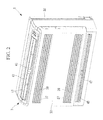
Fig. 2 is a perspective view showing the appearance of an indoor unit according to the embodiment of the present invention. -
Fig. 3 is a cross-sectional view of the indoor unit according to the embodiment of the present invention. -
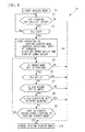
Fig. 4 is a flowchart showing a heating startup mode according to the embodiment of the present invention. - An
air conditioner 1 according to an embodiment of the present invention will now be described with reference toFigs. 1 to 4 . Thisair conditioner 1 is an example of a floor-standing air conditioner that blows air in two directions, namely, upper and lower directions. -
Fig. 1 shows a diagram of the refrigeration cycle of theair conditioner 1. - The
air conditioner 1 includes anoutdoor unit 3 and anindoor unit 5. - The
outdoor unit 3 includes an inverter-drivencompressor 7 for compressing a refrigerant, a four-way switch valve 9 for switching the direction in which the refrigerant is circulated, anoutdoor heat exchanger 11 for heat exchange between the refrigerant and outdoor air, anexpansion valve 13 functioning as a refrigerant-throttling mechanism, and anoutdoor air fan 15 for introducing outdoor air and causing it to pass through theoutdoor heat exchanger 11. - The
indoor unit 5 includes anindoor heat exchanger 17 supplied with the refrigerant from theoutdoor unit 3 and a turbofan (blower) 19 serving as an indoor air fan for introducing air from the interior of a room and, when the air passes through theindoor heat exchanger 17, blowing out conditioned air that has been subjected to heat exchange with the refrigerant. - The
indoor heat exchanger 17 is, for example, of a plate-fin tube type. - The
compressor 7, the four-way valve 9, theoutdoor heat exchanger 11, and theexpansion valve 13 in theoutdoor unit 3 are coupled to theindoor heat exchanger 17 in theindoor unit 5 throughrefrigerant piping 21 to constitute a refrigeration cycle. - The
indoor unit 5 includes acontroller 23 for controlling the operation of theair conditioner 1. - The
indoor unit 5 includes an indoor-air temperature sensor (intake-air-temperature detecting means) 25 for detecting the temperature of the indoor air introduced from the interior of the room and an indoor-heat-exchanger temperature sensor (indoor-heat-exchanger-temperature detecting means) 27 for detecting the temperature of theindoor heat exchanger 17. - The temperature of the indoor air detected by the indoor-
air temperature sensor 25 and the temperature of theindoor heat exchanger 17 detected by the indoor-heat-exchanger temperature sensor 27 are input to thecontroller 23. -
Fig. 2 is a perspective view showing the appearance of theindoor unit 5.Fig. 3 is a cross-sectional view of theindoor unit 5. - The
indoor unit 5 is of a floor-standing type that blows air in two directions, namely, upper and lower directions, and includes a horizontally oriented, substantiallyrectangular casing 35 composed of abase 31 and afront panel 33. - The
front panel 33 has twoinlets 37 separated vertically in the front surface thereof to take in indoor air. Theinlets 37 haveinlet grilles 39. - An
upper outlet 41 is provided horizontally in the longitudinal direction between the front and top surfaces of thefront panel 33. Theupper outlet 41 can be opened up and closed off by ahorizontal louver 43 rotatably disposed at the opening thereof. - A
lower outlet 45 is provided horizontally in the longitudinal direction at the bottom of thefront panel 33. Thelower outlet 45 can be opened up and closed off by ahorizontal louver 47 rotatably disposed at the opening thereof. - In the
casing 35, anair filter 49 is attachably/detachably disposed behind theinlet grilles 39, and theindoor heat exchanger 17 is fixed behind theair filter 49. - A
drain pan 51 is disposed under theindoor heat exchanger 17 to catch drain water condensed on the surface of theindoor heat exchanger 17 and dropping therefrom during cooling and dehumidifying modes and to drain it to the outside through a drain hose (not shown). - A
bellmouth 53 is disposed behind the indoor heat exchanger 17 (downstream in the airflow direction) to guide air communicated through theindoor heat exchanger 17 to theturbofan 19 disposed downstream thereof. - A circular-bell-shaped
inlet 55 is disposed in the center of thebellmouth 53 so as to face theturbofan 19. In addition, theturbofan 19 is disposed downstream of thebellmouth 53 so as to face theinlet 55. - The
turbofan 19 is composed of abase plate 57, ashroud 59, and a plurality ofblades 61. The center of thebase plate 57 is fixed to an end of arotating shaft 65 of amotor 63 fixed to the base 31 so that themotor 63 rotates theturbofan 19 about a horizontal axis. - The conditioned air blown radially through the
turbofan 19 is blown outward from the periphery of theturbofan 19 at a certain angle with respect to the tangential direction thereof. - An air-guiding
channel 67 for guiding the conditioned air blown from theturbofan 19 to theupper outlet 41 is formed between the base 31 and thebellmouth 53. - An air-guiding
channel 69 for guiding the conditioned air blown from theturbofan 19 to thelower outlet 45 is formed between the base 31 and thebellmouth 53. -
Nose portions turbofan 19 are formed integrally with the base 31 so as to constitute the air-guidingchannels - The upper air-guiding
channel 67 has a plurality of vertical louvers 75 arranged in the longitudinal direction of theupper outlet 41. The vertical louvers 75 are each disposed so as to be rotatable about a vertical axis and are coupled together. - The lower air-guiding
channel 69 has a plurality ofvertical louvers 77 arranged in the longitudinal direction of thelower outlet 45. Thevertical louvers 77 are each disposed so as to be rotatable about a vertical axis and are coupled together. - The
controller 23 receives detected values input from the individual sensors and various settings designated by the user and outputs control signals based on a predetermined program to control the operation of theair conditioner 1. - The
controller 23 controls, for example, the on/off state and the rotational speed of thecompressor 7, flow switching by the four-way valve 9, the on/off state and the rotational speed of theturbofan 19 and theoutdoor air fan 15, and the opening/closing of theupper outlet 41 and thelower outlet 45. - The
controller 23 has aheating startup mode 79 that is entered upon starting up in a heating mode and in which the conditioned air blown from theturbofan 19 is blown into the interior of the room only from thelower outlet 45 for a predetermined period of time if the air volume is set to an automatic mode and the air direction is set to a mode in which the air is blown from both theupper outlet 41 and thelower outlet 45. - In the thus-configured
air conditioner 1, the direction in which the refrigerant is circulated in the cooling mode and the heating mode is as follows. - In the cooling mode, the refrigerant is circulated in the direction indicated by the solid-line arrows in
Fig. 1 . As a result, theoutdoor heat exchanger 11 functions as a heat radiator (evaporator), whereas theindoor heat exchanger 17 functions as a heat absorber (condenser). Accordingly, the refrigerant absorbs heat from the indoor air passing through theindoor heat exchanger 17 to decrease the temperature thereof before the conditioned air is blown into the interior of the room. - In the heating mode, the refrigerant is circulated in the direction indicated by the broken-line arrows in
Fig. 1 . As a result, theindoor heat exchanger 17 functions as a heat radiator (evaporator), whereas theoutdoor heat exchanger 11 functions as a heat absorber (condenser). Accordingly, the refrigerant radiates heat into the indoor air passing through theindoor heat exchanger 17 to increase the temperature thereof before the conditioned air is blown into the interior of the room. - The conditioned air is blown from the
turbofan 19 in theindoor unit 5 as follows. - As the
turbofan 19 is rotated, the indoor air is taken into thecasing 35 through theinlets 37 via theinlet grilles 39. - After dust is removed from the air by the
air filter 49, the air is cooled or heated by heat exchange with the refrigerant while passing through theindoor heat exchanger 17, thus generating conditioned air. - While being guided by the
bellmouth 53, the conditioned air is taken through the bell-shapedinlet 55 into theturbofan 19, which increases the pressure thereof. - The conditioned air whose pressure has been increased by the
turbofan 19 is blown outward from the periphery of theturbofan 19 at a certain angle with respect to the tangential direction thereof. - The conditioned air flows to the
upper outlet 41 and/or thelower outlet 45 through the air-guidingchannels nose portions - The conditioned air is selectively blown into the interior of the room via either or both of the
upper outlet 41 and thelower outlet 45, depending on the preset blowing mode. - Next, the operation in the
heating startup mode 79 will be described with reference toFig. 4 . -
Fig. 4 is a flowchart showing theheating startup mode 79. - The user inputs the individual settings such as the preset temperature SP, the air volume, and the air direction to start a heating mode (Step S1).
- In setting the air volume, the user specifically designates, for example, "high", "med", or "low", or designates "auto", in which the
controller 23 determines the optimum air volume based on information from the individual sensors. - In setting the air direction, the user designates both the
upper outlet 41 and the lower outlet 45 (bidirectional blowing) or either of them. - The
controller 23 determines whether or not the criteria for starting theheating startup mode 79 are satisfied (Step S2). - The starting criteria are that the air volume is set to "auto" and that the air direction is set to bidirectional blowing.
- If the starting criteria are not satisfied (NO), the
controller 23 cancels the heating startup mode 79 (Step S10). - If the starting criteria are satisfied (YES), the
controller 23 determines whether the temperature Th2 of theindoor heat exchanger 17 detected by the indoor-heat-exchanger temperature sensor 27 is higher than a predetermined temperature Sh2 (Step S3) . - The predetermined temperature Sh2 is the temperature of the
indoor heat exchanger 17 required for the conditioned air passing therethrough to reach a desired temperature, and is set to, for example, 28°C. - If the detected temperature Th2 is lower than the predetermined temperature Sh2 (NO), the
controller 23 suspends operation in theheating startup mode 79. - This prevents blowing of conditioned air with low temperature, thus avoiding user discomfort due to operation in the
heating startup mode 79. - In addition, for example, if a warm-up timer causes the
air conditioner 1 to operate in a warm-up (preset operation) mode, thecontroller 23 may suspend operation in theheating startup mode 79 and, if necessary, may start operation in theheating startup mode 79 after the preset time of the warm-up timer has passed. - If the detected temperature Th2 is higher than the predetermined temperature Sh2 (YES), the
controller 23 starts operation in the heating startup mode 79 (Step S4). - That is, in the state shown in
Fig. 2 , in which both theupper outlet 41 and thelower outlet 45 are opened in the bidirectional blowing mode, theupper outlet 41 is closed off by rotating thehorizontal louver 43. As a result, the conditioned air blows only from thelower outlet 45. - In addition, the rotational speed of the
turbofan 19 is increased. - In this case, the conditioned air distributed to the
upper outlet 41 and thelower outlet 45 is blown only from thelower outlet 45. This increases the volume of conditioned air blown from thelower outlet 45, even though some of the air remains inside. - In addition, the conditioned air blown from the
lower outlet 45 is not affected by rising of conditioned air blown from theupper outlet 41. This prevents rising of the conditioned air blown from thelower outlet 45. - Accordingly, the reach of the conditioned air, namely, warm air, is extended so that it can be blown farther away. In particular, the reach of the warm air is extended toward the user's feet.
- If the conditioned air is blown only from the
lower outlet 45, the total air volume becomes slightly lower than the case where the conditioned air is blown from theupper outlet 41 and thelower outlet 45, and accordingly, the temperature of the conditioned air being blown is increased. - Thus, the operation in the
heating startup mode 79 allows conditioned air with a higher temperature to be blown far away, thus satisfying the user's demand for immediately having a feeling of warmth. - During the operation in the
heating startup mode 79, the air direction apparently differs from the mode in which the conditioned air is blown from theupper outlet 41 and thelower outlet 45. This may mislead the user into thinking that a problem has occurred. To avoid such misunderstanding, for example, an indication such as "rapid heating in progress" may be displayed, or a high-power lamp may light up or blink. - Because the blowing speed of the
turbofan 19 increases in theheating startup mode 79, the volume and speed of the conditioned air blown from thelower outlet 45 can be increased. - This allows a larger volume of conditioned air to be blown farther away, thus more quickly satisfying the user's demand for immediately having a feeling of warmth.
- During the operation in the
heating startup mode 79, thecontroller 23 sequentially or randomly executes the decisions in Steps S5 to S9 to determine whether theheating startup mode 79 should be cancelled based on the independent decisions in Steps S5 to S9. - In Step S5, the
controller 23 determines whether or not the indoor mode is set to heating. If the indoor mode is set to another mode (NO), thecontroller 23 cancels theheating startup mode 79 because the prerequisite of currently performing the heating mode is missing. - In Step S6, the
controller 23 determines whether or not the difference between the temperature Th1, detected by the indoor-air temperature sensor 25, of the indoor air introduced from the interior of the room and the preset temperature SP is 2°C or less (where the preset temperature SP is higher). If the indoor air temperature Th1 enters the above range (YES), thecontroller 23 determines that the user has a feeling of warmth and cancels theheating startup mode 79. - The above temperature difference, namely, 2°C, is merely illustrative of a temperature difference within which the indoor air temperature Th1 is close to the preset temperature SP. The temperature difference is not limited thereto and may be selected in the range of, for example, -1°C to 3°C, depending on particular situations.
- In Step S7, the
controller 23 determines whether or not the air volume is set to "auto". If the air volume is set to another mode (NO), thecontroller 23 cancels theheating startup mode 79. - That is, if the air volume is changed from "auto" to, for example, "high", "med", or "low", the
controller 23 determines that the user demands that level of air volume and terminates theheating startup mode 79. - In Step S8, the
controller 23 determines whether or not the air direction is set to upper blowing, in which the conditioned air is blown only from theupper outlet 41. If the air direction is set to upper blowing (YES), thecontroller 23 cancels theheating startup mode 79. - That is, if the air direction is set to upper blowing, the
controller 23 determines that the user does not demand blowing of the conditioned air from thelower outlet 45 and terminates theheating startup mode 79. - As in Steps S7 and S8, the user's needs are given top priority so that user satisfaction can be improved.
- In Step S9, the
controller 23 determines whether or not 20 minutes (predetermined period of time) have passed since starting to operate in theheating startup mode 79. If 20 minutes have passed (YES), thecontroller 23 determines that the user has a sufficient feeling of warmth and cancels theheating startup mode 79. - The above predetermined period of time, namely, 20 minutes, is merely illustrative of a sufficient period of time for the user in the space being air-conditioned, such as the interior of a room, to have a feeling of warmth. The predetermined period of time may be selected in the range of, for example, 10 to 30 minutes, depending on particular situations.
- The present invention is not limited to the above embodiment; various modifications are permitted without departing from the spirit thereof.
- For example, the advantages of the invention can be provided even if Steps S5 to S8 are not necessarily used as the determination criteria for canceling the
heating startup mode 79; they may be used where needed.
Claims (5)
- An air conditioner comprising:vertically separated upper and lower outlets for blowing conditioned air supplied through an indoor heat exchanger by a blower into the interior of a room; anda controller for controlling operation,wherein the controller has a heating startup mode that is entered upon starting up in a heating mode and in which the conditioned air is blown only from the lower outlet for a predetermined period of time if the air volume is set to an automatic mode and the air direction is set to a mode in which the air is blown from both the upper outlet and the lower outlet.
- The air conditioner according to Claim 1, wherein the blowing speed of the blower increases in the heating startup mode.
- The air conditioner according to Claim 1 or 2,
wherein the heating startup mode is terminated before the predetermined period of time has passed if the setting of the air volume or the air direction is changed. - The air conditioner according to one of Claims 1 to 3, further comprising intake-air-temperature detecting means for detecting the temperature of indoor air taken into the indoor heat exchanger and inputting the temperature to the controller,
wherein the heating startup mode is terminated before the predetermined period of time has passed if the temperature of the indoor air approaches a preset heating temperature. - The air conditioner according to one of Claims 1 to 4, further comprising indoor-heat-exchanger-temperature detecting means for detecting the temperature of the indoor heat exchanger and inputting the temperature to the controller,
wherein the heating startup mode is not entered if the temperature of the indoor heat exchanger does not exceed a predetermined temperature.
Applications Claiming Priority (1)
| Application Number | Priority Date | Filing Date | Title |
|---|---|---|---|
| JP2008248557A JP2010078254A (en) | 2008-09-26 | 2008-09-26 | Air conditioner |
Publications (3)
| Publication Number | Publication Date |
|---|---|
| EP2169320A2 true EP2169320A2 (en) | 2010-03-31 |
| EP2169320A3 EP2169320A3 (en) | 2014-05-21 |
| EP2169320B1 EP2169320B1 (en) | 2015-07-29 |
Family
ID=41478634
Family Applications (1)
| Application Number | Title | Priority Date | Filing Date |
|---|---|---|---|
| EP09170894.1A Not-in-force EP2169320B1 (en) | 2008-09-26 | 2009-09-22 | Air conditioner |
Country Status (3)
| Country | Link |
|---|---|
| EP (1) | EP2169320B1 (en) |
| JP (1) | JP2010078254A (en) |
| ES (1) | ES2550262T3 (en) |
Cited By (7)
| Publication number | Priority date | Publication date | Assignee | Title |
|---|---|---|---|---|
| ITMI20110728A1 (en) * | 2011-04-29 | 2012-10-30 | Giordano Riello Internat Group S P A | FAN |
| CN110249187A (en) * | 2017-02-06 | 2019-09-17 | 大金工业株式会社 | Air conditioner |
| CN113959076A (en) * | 2021-10-22 | 2022-01-21 | 珠海格力电器股份有限公司 | Control method for air outlet of air conditioner and air conditioner |
| CN114110766A (en) * | 2020-08-31 | 2022-03-01 | 青岛海尔智能技术研发有限公司 | Air conditioner |
| CN114110767A (en) * | 2020-08-31 | 2022-03-01 | 青岛海尔智能技术研发有限公司 | Air conditioner |
| CN114110765A (en) * | 2020-08-31 | 2022-03-01 | 青岛海尔智能技术研发有限公司 | Air conditioner |
| EP4145050A4 (en) * | 2020-04-27 | 2023-11-08 | Qingdao Haier Air-Conditioning Electronic Co., Ltd | CONTROL METHOD FOR AIR CONDITIONER |
Families Citing this family (1)
| Publication number | Priority date | Publication date | Assignee | Title |
|---|---|---|---|---|
| CN106545922A (en) * | 2016-10-31 | 2017-03-29 | 芜湖美智空调设备有限公司 | A kind of floor air conditioner and its control method |
Citations (1)
| Publication number | Priority date | Publication date | Assignee | Title |
|---|---|---|---|---|
| JP2007198641A (en) | 2006-01-25 | 2007-08-09 | Daikin Ind Ltd | Floor-mounted air conditioning indoor unit |
Family Cites Families (10)
| Publication number | Priority date | Publication date | Assignee | Title |
|---|---|---|---|---|
| JPS61223448A (en) * | 1985-03-27 | 1986-10-04 | Toshiba Corp | Air-conditioning machine |
| JPS61228242A (en) * | 1985-04-01 | 1986-10-11 | Mitsubishi Electric Corp | Indoor unit for air conditioner |
| JPH05157320A (en) * | 1991-12-09 | 1993-06-22 | Toshiba Corp | Air conditioner |
| JP3446478B2 (en) * | 1996-05-10 | 2003-09-16 | ダイキン工業株式会社 | Air conditioner |
| JP3448471B2 (en) * | 1997-10-02 | 2003-09-22 | 三洋電機株式会社 | Judgment method of human detection and air conditioner |
| JP2953455B2 (en) * | 1998-02-20 | 1999-09-27 | ダイキン工業株式会社 | Air conditioner fan control device |
| JP2001272085A (en) * | 2000-03-28 | 2001-10-05 | Fujitsu General Ltd | Air conditioner |
| EP1726889A1 (en) * | 2005-05-21 | 2006-11-29 | Lg Electronics Inc. | Method for controlling an air conditioning unit |
| KR100755321B1 (en) * | 2005-06-15 | 2007-09-05 | 엘지전자 주식회사 | Air conditioner and control method |
| JP4123276B2 (en) * | 2006-01-04 | 2008-07-23 | ダイキン工業株式会社 | Air conditioner indoor unit |
-
2008
- 2008-09-26 JP JP2008248557A patent/JP2010078254A/en active Pending
-
2009
- 2009-09-22 ES ES09170894.1T patent/ES2550262T3/en active Active
- 2009-09-22 EP EP09170894.1A patent/EP2169320B1/en not_active Not-in-force
Patent Citations (1)
| Publication number | Priority date | Publication date | Assignee | Title |
|---|---|---|---|---|
| JP2007198641A (en) | 2006-01-25 | 2007-08-09 | Daikin Ind Ltd | Floor-mounted air conditioning indoor unit |
Cited By (8)
| Publication number | Priority date | Publication date | Assignee | Title |
|---|---|---|---|---|
| ITMI20110728A1 (en) * | 2011-04-29 | 2012-10-30 | Giordano Riello Internat Group S P A | FAN |
| CN110249187A (en) * | 2017-02-06 | 2019-09-17 | 大金工业株式会社 | Air conditioner |
| EP3578897A4 (en) * | 2017-02-06 | 2020-02-26 | Daikin Industries, Ltd. | AIR CONDITIONER |
| EP4145050A4 (en) * | 2020-04-27 | 2023-11-08 | Qingdao Haier Air-Conditioning Electronic Co., Ltd | CONTROL METHOD FOR AIR CONDITIONER |
| CN114110766A (en) * | 2020-08-31 | 2022-03-01 | 青岛海尔智能技术研发有限公司 | Air conditioner |
| CN114110767A (en) * | 2020-08-31 | 2022-03-01 | 青岛海尔智能技术研发有限公司 | Air conditioner |
| CN114110765A (en) * | 2020-08-31 | 2022-03-01 | 青岛海尔智能技术研发有限公司 | Air conditioner |
| CN113959076A (en) * | 2021-10-22 | 2022-01-21 | 珠海格力电器股份有限公司 | Control method for air outlet of air conditioner and air conditioner |
Also Published As
| Publication number | Publication date |
|---|---|
| EP2169320A3 (en) | 2014-05-21 |
| EP2169320B1 (en) | 2015-07-29 |
| JP2010078254A (en) | 2010-04-08 |
| ES2550262T3 (en) | 2015-11-05 |
Similar Documents
| Publication | Publication Date | Title |
|---|---|---|
| KR102794391B1 (en) | Air conditioner | |
| EP2169320B1 (en) | Air conditioner | |
| EP3555534B1 (en) | Air conditioner | |
| EP3183509B1 (en) | Air conditioner and control method thereof | |
| CN102278794B (en) | Air conditioning device | |
| JP6932009B2 (en) | Indoor unit of air conditioner | |
| CN109891161B (en) | Air conditioner | |
| KR102809591B1 (en) | Air conditioner and method for control of air conditioner | |
| JP6229741B2 (en) | Indoor unit of air conditioner | |
| EP3631307B1 (en) | Air conditioner | |
| JP4990841B2 (en) | Air conditioner | |
| CN101932885B (en) | Air conditioner | |
| KR20180039405A (en) | Air conditioner | |
| JP2004150679A (en) | Air conditioning system | |
| JPH1123046A (en) | Air conditioner heating control apparatus and method | |
| JP2017155953A (en) | Air conditioner | |
| KR101827293B1 (en) | An air conditioner | |
| JPH0336433A (en) | Air conditioner | |
| JP2004308930A (en) | Air conditioner | |
| JP2008261555A (en) | Air conditioner | |
| CN109489216B (en) | A control method of a comfortable air duct supply air conditioner | |
| EP2169321B1 (en) | Air conditioner | |
| JP4619983B2 (en) | Air conditioner | |
| JP6418147B2 (en) | air conditioner | |
| KR20180035291A (en) | Air conditioning system |
Legal Events
| Date | Code | Title | Description |
|---|---|---|---|
| PUAI | Public reference made under article 153(3) epc to a published international application that has entered the european phase |
Free format text: ORIGINAL CODE: 0009012 |
|
| AK | Designated contracting states |
Kind code of ref document: A2 Designated state(s): AT BE BG CH CY CZ DE DK EE ES FI FR GB GR HR HU IE IS IT LI LT LU LV MC MK MT NL NO PL PT RO SE SI SK SM TR |
|
| PUAL | Search report despatched |
Free format text: ORIGINAL CODE: 0009013 |
|
| AK | Designated contracting states |
Kind code of ref document: A3 Designated state(s): AT BE BG CH CY CZ DE DK EE ES FI FR GB GR HR HU IE IS IT LI LT LU LV MC MK MT NL NO PL PT RO SE SI SK SM TR |
|
| RIC1 | Information provided on ipc code assigned before grant |
Ipc: F24F 11/04 20060101ALN20140414BHEP Ipc: F24F 1/00 20110101AFI20140414BHEP Ipc: F24F 11/00 20060101ALI20140414BHEP |
|
| 17P | Request for examination filed |
Effective date: 20140923 |
|
| RBV | Designated contracting states (corrected) |
Designated state(s): AT BE BG CH CY CZ DE DK EE ES FI FR GB GR HR HU IE IS IT LI LT LU LV MC MK MT NL NO PL PT RO SE SI SK SM TR |
|
| GRAP | Despatch of communication of intention to grant a patent |
Free format text: ORIGINAL CODE: EPIDOSNIGR1 |
|
| RIC1 | Information provided on ipc code assigned before grant |
Ipc: F24F 11/00 20060101ALI20150121BHEP Ipc: F24F 1/00 20110101AFI20150121BHEP Ipc: F24F 11/04 20060101ALN20150121BHEP |
|
| INTG | Intention to grant announced |
Effective date: 20150216 |
|
| GRAS | Grant fee paid |
Free format text: ORIGINAL CODE: EPIDOSNIGR3 |
|
| GRAA | (expected) grant |
Free format text: ORIGINAL CODE: 0009210 |
|
| AK | Designated contracting states |
Kind code of ref document: B1 Designated state(s): AT BE BG CH CY CZ DE DK EE ES FI FR GB GR HR HU IE IS IT LI LT LU LV MC MK MT NL NO PL PT RO SE SI SK SM TR |
|
| REG | Reference to a national code |
Ref country code: GB Ref legal event code: FG4D |
|
| REG | Reference to a national code |
Ref country code: CH Ref legal event code: EP |
|
| REG | Reference to a national code |
Ref country code: AT Ref legal event code: REF Ref document number: 739640 Country of ref document: AT Kind code of ref document: T Effective date: 20150815 |
|
| REG | Reference to a national code |
Ref country code: IE Ref legal event code: FG4D |
|
| REG | Reference to a national code |
Ref country code: DE Ref legal event code: R096 Ref document number: 602009032450 Country of ref document: DE |
|
| REG | Reference to a national code |
Ref country code: ES Ref legal event code: FG2A Ref document number: 2550262 Country of ref document: ES Kind code of ref document: T3 Effective date: 20151105 |
|
| REG | Reference to a national code |
Ref country code: AT Ref legal event code: MK05 Ref document number: 739640 Country of ref document: AT Kind code of ref document: T Effective date: 20150729 |
|
| REG | Reference to a national code |
Ref country code: LT Ref legal event code: MG4D |
|
| REG | Reference to a national code |
Ref country code: NL Ref legal event code: MP Effective date: 20150729 |
|
| PG25 | Lapsed in a contracting state [announced via postgrant information from national office to epo] |
Ref country code: GR Free format text: LAPSE BECAUSE OF FAILURE TO SUBMIT A TRANSLATION OF THE DESCRIPTION OR TO PAY THE FEE WITHIN THE PRESCRIBED TIME-LIMIT Effective date: 20151030 Ref country code: NO Free format text: LAPSE BECAUSE OF FAILURE TO SUBMIT A TRANSLATION OF THE DESCRIPTION OR TO PAY THE FEE WITHIN THE PRESCRIBED TIME-LIMIT Effective date: 20151029 Ref country code: LV Free format text: LAPSE BECAUSE OF FAILURE TO SUBMIT A TRANSLATION OF THE DESCRIPTION OR TO PAY THE FEE WITHIN THE PRESCRIBED TIME-LIMIT Effective date: 20150729 Ref country code: LT Free format text: LAPSE BECAUSE OF FAILURE TO SUBMIT A TRANSLATION OF THE DESCRIPTION OR TO PAY THE FEE WITHIN THE PRESCRIBED TIME-LIMIT Effective date: 20150729 Ref country code: FI Free format text: LAPSE BECAUSE OF FAILURE TO SUBMIT A TRANSLATION OF THE DESCRIPTION OR TO PAY THE FEE WITHIN THE PRESCRIBED TIME-LIMIT Effective date: 20150729 |
|
| PG25 | Lapsed in a contracting state [announced via postgrant information from national office to epo] |
Ref country code: IS Free format text: LAPSE BECAUSE OF FAILURE TO SUBMIT A TRANSLATION OF THE DESCRIPTION OR TO PAY THE FEE WITHIN THE PRESCRIBED TIME-LIMIT Effective date: 20151129 Ref country code: SE Free format text: LAPSE BECAUSE OF FAILURE TO SUBMIT A TRANSLATION OF THE DESCRIPTION OR TO PAY THE FEE WITHIN THE PRESCRIBED TIME-LIMIT Effective date: 20150729 Ref country code: PL Free format text: LAPSE BECAUSE OF FAILURE TO SUBMIT A TRANSLATION OF THE DESCRIPTION OR TO PAY THE FEE WITHIN THE PRESCRIBED TIME-LIMIT Effective date: 20150729 Ref country code: AT Free format text: LAPSE BECAUSE OF FAILURE TO SUBMIT A TRANSLATION OF THE DESCRIPTION OR TO PAY THE FEE WITHIN THE PRESCRIBED TIME-LIMIT Effective date: 20150729 Ref country code: HR Free format text: LAPSE BECAUSE OF FAILURE TO SUBMIT A TRANSLATION OF THE DESCRIPTION OR TO PAY THE FEE WITHIN THE PRESCRIBED TIME-LIMIT Effective date: 20150729 Ref country code: PT Free format text: LAPSE BECAUSE OF FAILURE TO SUBMIT A TRANSLATION OF THE DESCRIPTION OR TO PAY THE FEE WITHIN THE PRESCRIBED TIME-LIMIT Effective date: 20151130 |
|
| PG25 | Lapsed in a contracting state [announced via postgrant information from national office to epo] |
Ref country code: NL Free format text: LAPSE BECAUSE OF FAILURE TO SUBMIT A TRANSLATION OF THE DESCRIPTION OR TO PAY THE FEE WITHIN THE PRESCRIBED TIME-LIMIT Effective date: 20150729 |
|
| PG25 | Lapsed in a contracting state [announced via postgrant information from national office to epo] |
Ref country code: MC Free format text: LAPSE BECAUSE OF FAILURE TO SUBMIT A TRANSLATION OF THE DESCRIPTION OR TO PAY THE FEE WITHIN THE PRESCRIBED TIME-LIMIT Effective date: 20150729 Ref country code: DK Free format text: LAPSE BECAUSE OF FAILURE TO SUBMIT A TRANSLATION OF THE DESCRIPTION OR TO PAY THE FEE WITHIN THE PRESCRIBED TIME-LIMIT Effective date: 20150729 Ref country code: CZ Free format text: LAPSE BECAUSE OF FAILURE TO SUBMIT A TRANSLATION OF THE DESCRIPTION OR TO PAY THE FEE WITHIN THE PRESCRIBED TIME-LIMIT Effective date: 20150729 Ref country code: EE Free format text: LAPSE BECAUSE OF FAILURE TO SUBMIT A TRANSLATION OF THE DESCRIPTION OR TO PAY THE FEE WITHIN THE PRESCRIBED TIME-LIMIT Effective date: 20150729 Ref country code: SK Free format text: LAPSE BECAUSE OF FAILURE TO SUBMIT A TRANSLATION OF THE DESCRIPTION OR TO PAY THE FEE WITHIN THE PRESCRIBED TIME-LIMIT Effective date: 20150729 Ref country code: LU Free format text: LAPSE BECAUSE OF FAILURE TO SUBMIT A TRANSLATION OF THE DESCRIPTION OR TO PAY THE FEE WITHIN THE PRESCRIBED TIME-LIMIT Effective date: 20150922 |
|
| REG | Reference to a national code |
Ref country code: CH Ref legal event code: PL |
|
| REG | Reference to a national code |
Ref country code: DE Ref legal event code: R097 Ref document number: 602009032450 Country of ref document: DE |
|
| PG25 | Lapsed in a contracting state [announced via postgrant information from national office to epo] |
Ref country code: RO Free format text: LAPSE BECAUSE OF FAILURE TO SUBMIT A TRANSLATION OF THE DESCRIPTION OR TO PAY THE FEE WITHIN THE PRESCRIBED TIME-LIMIT Effective date: 20150729 |
|
| PLBE | No opposition filed within time limit |
Free format text: ORIGINAL CODE: 0009261 |
|
| STAA | Information on the status of an ep patent application or granted ep patent |
Free format text: STATUS: NO OPPOSITION FILED WITHIN TIME LIMIT |
|
| REG | Reference to a national code |
Ref country code: IE Ref legal event code: MM4A |
|
| REG | Reference to a national code |
Ref country code: FR Ref legal event code: ST Effective date: 20160531 |
|
| 26N | No opposition filed |
Effective date: 20160502 |
|
| PG25 | Lapsed in a contracting state [announced via postgrant information from national office to epo] |
Ref country code: IE Free format text: LAPSE BECAUSE OF NON-PAYMENT OF DUE FEES Effective date: 20150922 Ref country code: LI Free format text: LAPSE BECAUSE OF NON-PAYMENT OF DUE FEES Effective date: 20150930 Ref country code: CH Free format text: LAPSE BECAUSE OF NON-PAYMENT OF DUE FEES Effective date: 20150930 |
|
| PG25 | Lapsed in a contracting state [announced via postgrant information from national office to epo] |
Ref country code: FR Free format text: LAPSE BECAUSE OF NON-PAYMENT OF DUE FEES Effective date: 20150930 Ref country code: SI Free format text: LAPSE BECAUSE OF FAILURE TO SUBMIT A TRANSLATION OF THE DESCRIPTION OR TO PAY THE FEE WITHIN THE PRESCRIBED TIME-LIMIT Effective date: 20150729 |
|
| PG25 | Lapsed in a contracting state [announced via postgrant information from national office to epo] |
Ref country code: BE Free format text: LAPSE BECAUSE OF FAILURE TO SUBMIT A TRANSLATION OF THE DESCRIPTION OR TO PAY THE FEE WITHIN THE PRESCRIBED TIME-LIMIT Effective date: 20150729 |
|
| PG25 | Lapsed in a contracting state [announced via postgrant information from national office to epo] |
Ref country code: MT Free format text: LAPSE BECAUSE OF FAILURE TO SUBMIT A TRANSLATION OF THE DESCRIPTION OR TO PAY THE FEE WITHIN THE PRESCRIBED TIME-LIMIT Effective date: 20150729 |
|
| PG25 | Lapsed in a contracting state [announced via postgrant information from national office to epo] |
Ref country code: SM Free format text: LAPSE BECAUSE OF FAILURE TO SUBMIT A TRANSLATION OF THE DESCRIPTION OR TO PAY THE FEE WITHIN THE PRESCRIBED TIME-LIMIT Effective date: 20150729 Ref country code: HU Free format text: LAPSE BECAUSE OF FAILURE TO SUBMIT A TRANSLATION OF THE DESCRIPTION OR TO PAY THE FEE WITHIN THE PRESCRIBED TIME-LIMIT; INVALID AB INITIO Effective date: 20090922 Ref country code: BG Free format text: LAPSE BECAUSE OF FAILURE TO SUBMIT A TRANSLATION OF THE DESCRIPTION OR TO PAY THE FEE WITHIN THE PRESCRIBED TIME-LIMIT Effective date: 20150729 |
|
| PG25 | Lapsed in a contracting state [announced via postgrant information from national office to epo] |
Ref country code: CY Free format text: LAPSE BECAUSE OF FAILURE TO SUBMIT A TRANSLATION OF THE DESCRIPTION OR TO PAY THE FEE WITHIN THE PRESCRIBED TIME-LIMIT Effective date: 20150729 |
|
| PG25 | Lapsed in a contracting state [announced via postgrant information from national office to epo] |
Ref country code: TR Free format text: LAPSE BECAUSE OF FAILURE TO SUBMIT A TRANSLATION OF THE DESCRIPTION OR TO PAY THE FEE WITHIN THE PRESCRIBED TIME-LIMIT Effective date: 20150729 |
|
| REG | Reference to a national code |
Ref country code: DE Ref legal event code: R082 Ref document number: 602009032450 Country of ref document: DE Representative=s name: KOHLER SCHMID MOEBUS PATENTANWAELTE PARTNERSCH, DE Ref country code: DE Ref legal event code: R081 Ref document number: 602009032450 Country of ref document: DE Owner name: MITSUBISHI HEAVY INDUSTRIES THERMAL SYSTEMS, L, JP Free format text: FORMER OWNER: MITSUBISHI HEAVY INDUSTRIES, LTD., TOKYO, JP |
|
| REG | Reference to a national code |
Ref country code: GB Ref legal event code: 732E Free format text: REGISTERED BETWEEN 20171130 AND 20171206 |
|
| PG25 | Lapsed in a contracting state [announced via postgrant information from national office to epo] |
Ref country code: MK Free format text: LAPSE BECAUSE OF FAILURE TO SUBMIT A TRANSLATION OF THE DESCRIPTION OR TO PAY THE FEE WITHIN THE PRESCRIBED TIME-LIMIT Effective date: 20150729 |
|
| PGFP | Annual fee paid to national office [announced via postgrant information from national office to epo] |
Ref country code: DE Payment date: 20190910 Year of fee payment: 11 Ref country code: IT Payment date: 20190917 Year of fee payment: 11 |
|
| PGFP | Annual fee paid to national office [announced via postgrant information from national office to epo] |
Ref country code: GB Payment date: 20190920 Year of fee payment: 11 |
|
| PGFP | Annual fee paid to national office [announced via postgrant information from national office to epo] |
Ref country code: ES Payment date: 20191002 Year of fee payment: 11 |
|
| REG | Reference to a national code |
Ref country code: DE Ref legal event code: R119 Ref document number: 602009032450 Country of ref document: DE |
|
| GBPC | Gb: european patent ceased through non-payment of renewal fee |
Effective date: 20200922 |
|
| PG25 | Lapsed in a contracting state [announced via postgrant information from national office to epo] |
Ref country code: DE Free format text: LAPSE BECAUSE OF NON-PAYMENT OF DUE FEES Effective date: 20210401 |
|
| PG25 | Lapsed in a contracting state [announced via postgrant information from national office to epo] |
Ref country code: GB Free format text: LAPSE BECAUSE OF NON-PAYMENT OF DUE FEES Effective date: 20200922 |
|
| PG25 | Lapsed in a contracting state [announced via postgrant information from national office to epo] |
Ref country code: IT Free format text: LAPSE BECAUSE OF NON-PAYMENT OF DUE FEES Effective date: 20200922 |
|
| REG | Reference to a national code |
Ref country code: ES Ref legal event code: FD2A Effective date: 20220118 |
|
| PG25 | Lapsed in a contracting state [announced via postgrant information from national office to epo] |
Ref country code: ES Free format text: LAPSE BECAUSE OF NON-PAYMENT OF DUE FEES Effective date: 20200923 |