EP2169184A2 - Apparatus and method for removing gas turbine compressor stator vane segments with rotor in place - Google Patents
Apparatus and method for removing gas turbine compressor stator vane segments with rotor in place Download PDFInfo
- Publication number
- EP2169184A2 EP2169184A2 EP09170403A EP09170403A EP2169184A2 EP 2169184 A2 EP2169184 A2 EP 2169184A2 EP 09170403 A EP09170403 A EP 09170403A EP 09170403 A EP09170403 A EP 09170403A EP 2169184 A2 EP2169184 A2 EP 2169184A2
- Authority
- EP
- European Patent Office
- Prior art keywords
- stator vane
- casing
- vane segment
- tension
- slot
- Prior art date
- Legal status (The legal status is an assumption and is not a legal conclusion. Google has not performed a legal analysis and makes no representation as to the accuracy of the status listed.)
- Granted
Links
Images




Classifications
-
- F—MECHANICAL ENGINEERING; LIGHTING; HEATING; WEAPONS; BLASTING
- F01—MACHINES OR ENGINES IN GENERAL; ENGINE PLANTS IN GENERAL; STEAM ENGINES
- F01D—NON-POSITIVE DISPLACEMENT MACHINES OR ENGINES, e.g. STEAM TURBINES
- F01D9/00—Stators
- F01D9/02—Nozzles; Nozzle boxes; Stator blades; Guide conduits, e.g. individual nozzles
- F01D9/04—Nozzles; Nozzle boxes; Stator blades; Guide conduits, e.g. individual nozzles forming ring or sector
- F01D9/041—Nozzles; Nozzle boxes; Stator blades; Guide conduits, e.g. individual nozzles forming ring or sector using blades
-
- B—PERFORMING OPERATIONS; TRANSPORTING
- B23—MACHINE TOOLS; METAL-WORKING NOT OTHERWISE PROVIDED FOR
- B23P—METAL-WORKING NOT OTHERWISE PROVIDED FOR; COMBINED OPERATIONS; UNIVERSAL MACHINE TOOLS
- B23P19/00—Machines for simply fitting together or separating metal parts or objects, or metal and non-metal parts, whether or not involving some deformation; Tools or devices therefor so far as not provided for in other classes
- B23P19/02—Machines for simply fitting together or separating metal parts or objects, or metal and non-metal parts, whether or not involving some deformation; Tools or devices therefor so far as not provided for in other classes for connecting objects by press fit or for detaching same
- B23P19/025—For detaching only
-
- B—PERFORMING OPERATIONS; TRANSPORTING
- B23—MACHINE TOOLS; METAL-WORKING NOT OTHERWISE PROVIDED FOR
- B23P—METAL-WORKING NOT OTHERWISE PROVIDED FOR; COMBINED OPERATIONS; UNIVERSAL MACHINE TOOLS
- B23P6/00—Restoring or reconditioning objects
- B23P6/002—Repairing turbine components, e.g. moving or stationary blades, rotors
-
- F—MECHANICAL ENGINEERING; LIGHTING; HEATING; WEAPONS; BLASTING
- F01—MACHINES OR ENGINES IN GENERAL; ENGINE PLANTS IN GENERAL; STEAM ENGINES
- F01D—NON-POSITIVE DISPLACEMENT MACHINES OR ENGINES, e.g. STEAM TURBINES
- F01D25/00—Component parts, details, or accessories, not provided for in, or of interest apart from, other groups
- F01D25/28—Supporting or mounting arrangements, e.g. for turbine casing
- F01D25/285—Temporary support structures, e.g. for testing, assembling, installing, repairing; Assembly methods using such structures
-
- F—MECHANICAL ENGINEERING; LIGHTING; HEATING; WEAPONS; BLASTING
- F01—MACHINES OR ENGINES IN GENERAL; ENGINE PLANTS IN GENERAL; STEAM ENGINES
- F01D—NON-POSITIVE DISPLACEMENT MACHINES OR ENGINES, e.g. STEAM TURBINES
- F01D9/00—Stators
- F01D9/02—Nozzles; Nozzle boxes; Stator blades; Guide conduits, e.g. individual nozzles
- F01D9/04—Nozzles; Nozzle boxes; Stator blades; Guide conduits, e.g. individual nozzles forming ring or sector
- F01D9/042—Nozzles; Nozzle boxes; Stator blades; Guide conduits, e.g. individual nozzles forming ring or sector fixing blades to stators
-
- Y—GENERAL TAGGING OF NEW TECHNOLOGICAL DEVELOPMENTS; GENERAL TAGGING OF CROSS-SECTIONAL TECHNOLOGIES SPANNING OVER SEVERAL SECTIONS OF THE IPC; TECHNICAL SUBJECTS COVERED BY FORMER USPC CROSS-REFERENCE ART COLLECTIONS [XRACs] AND DIGESTS
- Y10—TECHNICAL SUBJECTS COVERED BY FORMER USPC
- Y10T—TECHNICAL SUBJECTS COVERED BY FORMER US CLASSIFICATION
- Y10T29/00—Metal working
- Y10T29/49—Method of mechanical manufacture
- Y10T29/49229—Prime mover or fluid pump making
- Y10T29/49236—Fluid pump or compressor making
- Y10T29/49238—Repairing, converting, servicing or salvaging
-
- Y—GENERAL TAGGING OF NEW TECHNOLOGICAL DEVELOPMENTS; GENERAL TAGGING OF CROSS-SECTIONAL TECHNOLOGIES SPANNING OVER SEVERAL SECTIONS OF THE IPC; TECHNICAL SUBJECTS COVERED BY FORMER USPC CROSS-REFERENCE ART COLLECTIONS [XRACs] AND DIGESTS
- Y10—TECHNICAL SUBJECTS COVERED BY FORMER USPC
- Y10T—TECHNICAL SUBJECTS COVERED BY FORMER US CLASSIFICATION
- Y10T29/00—Metal working
- Y10T29/49—Method of mechanical manufacture
- Y10T29/49316—Impeller making
- Y10T29/49318—Repairing or disassembling
-
- Y—GENERAL TAGGING OF NEW TECHNOLOGICAL DEVELOPMENTS; GENERAL TAGGING OF CROSS-SECTIONAL TECHNOLOGIES SPANNING OVER SEVERAL SECTIONS OF THE IPC; TECHNICAL SUBJECTS COVERED BY FORMER USPC CROSS-REFERENCE ART COLLECTIONS [XRACs] AND DIGESTS
- Y10—TECHNICAL SUBJECTS COVERED BY FORMER USPC
- Y10T—TECHNICAL SUBJECTS COVERED BY FORMER US CLASSIFICATION
- Y10T29/00—Metal working
- Y10T29/49—Method of mechanical manufacture
- Y10T29/49815—Disassembling
- Y10T29/49822—Disassembling by applying force
-
- Y—GENERAL TAGGING OF NEW TECHNOLOGICAL DEVELOPMENTS; GENERAL TAGGING OF CROSS-SECTIONAL TECHNOLOGIES SPANNING OVER SEVERAL SECTIONS OF THE IPC; TECHNICAL SUBJECTS COVERED BY FORMER USPC CROSS-REFERENCE ART COLLECTIONS [XRACs] AND DIGESTS
- Y10—TECHNICAL SUBJECTS COVERED BY FORMER USPC
- Y10T—TECHNICAL SUBJECTS COVERED BY FORMER US CLASSIFICATION
- Y10T29/00—Metal working
- Y10T29/53—Means to assemble or disassemble
-
- Y—GENERAL TAGGING OF NEW TECHNOLOGICAL DEVELOPMENTS; GENERAL TAGGING OF CROSS-SECTIONAL TECHNOLOGIES SPANNING OVER SEVERAL SECTIONS OF THE IPC; TECHNICAL SUBJECTS COVERED BY FORMER USPC CROSS-REFERENCE ART COLLECTIONS [XRACs] AND DIGESTS
- Y10—TECHNICAL SUBJECTS COVERED BY FORMER USPC
- Y10T—TECHNICAL SUBJECTS COVERED BY FORMER US CLASSIFICATION
- Y10T29/00—Metal working
- Y10T29/53—Means to assemble or disassemble
- Y10T29/53796—Puller or pusher means, contained force multiplying operator
-
- Y—GENERAL TAGGING OF NEW TECHNOLOGICAL DEVELOPMENTS; GENERAL TAGGING OF CROSS-SECTIONAL TECHNOLOGIES SPANNING OVER SEVERAL SECTIONS OF THE IPC; TECHNICAL SUBJECTS COVERED BY FORMER USPC CROSS-REFERENCE ART COLLECTIONS [XRACs] AND DIGESTS
- Y10—TECHNICAL SUBJECTS COVERED BY FORMER USPC
- Y10T—TECHNICAL SUBJECTS COVERED BY FORMER US CLASSIFICATION
- Y10T29/00—Metal working
- Y10T29/53—Means to assemble or disassemble
- Y10T29/53796—Puller or pusher means, contained force multiplying operator
- Y10T29/53839—Puller or pusher means, contained force multiplying operator having percussion or explosive operator
-
- Y—GENERAL TAGGING OF NEW TECHNOLOGICAL DEVELOPMENTS; GENERAL TAGGING OF CROSS-SECTIONAL TECHNOLOGIES SPANNING OVER SEVERAL SECTIONS OF THE IPC; TECHNICAL SUBJECTS COVERED BY FORMER USPC CROSS-REFERENCE ART COLLECTIONS [XRACs] AND DIGESTS
- Y10—TECHNICAL SUBJECTS COVERED BY FORMER USPC
- Y10T—TECHNICAL SUBJECTS COVERED BY FORMER US CLASSIFICATION
- Y10T29/00—Metal working
- Y10T29/53—Means to assemble or disassemble
- Y10T29/53909—Means comprising hand manipulatable tool
- Y10T29/5393—Means comprising impact receiving tool
Definitions
- the invention relates generally to a gas turbine compressor and more specifically to an apparatus and method for removing stator vane segments of a gas turbine compressor with the rotor for the gas turbine compressor in place.
- a conventional gas turbine generally operates on the principle of compressing air within a compressor and then delivering the compressed air to a combustion chamber where fuel is added to the air and ignited. Afterwards, the resulting combustion mixture is delivered to the turbine section of the gas turbine where a portion of the energy, generated by the combustion process, is extracted by a turbine to drive the compressor via a shaft.
- stators are placed at the entrance and exit of the compressor section, as well as between each compressor stage, for purposes of properly directing the airflow to each successive compressor stage.
- stators are able to enhance compressor performance by appropriately influencing airflow and pressure within the compressor section.
- Stators generally consist of an annular array of airfoils or vanes. Stators are typically formed in segments as stator vane segments consisting of one or more airfoils supported by the base. The base includes a dovetailed to maintain the stator vane unit within the casing. These stator vane segments are individually mounted to the compressor casing to form an annular array, so that the airfoils project radially between an adjacent pair of compressor stages. For this type of installation, a plurality of stator vane segments, with multiple blades, are assembled in the casing slot to form a stage.
- FIG. 1 illustrates a top view of a lower-half casing for a compressor with the rotor removed, showing several individual casing slots for the assembly of stator vane stages.
- FIG. 2 illustrates a sectional view of a base of the stator vane segment within an individual casing slot.
- the casing 10 has a plurality of slots 20 in horizontal flanges 15 for receiving the stator vane segments 50.
- a first casing slot 21 is shown without the stator vane segment.
- Other casing slots 22 include stator vane segments 50 with vanes 60.
- the slot 20 has a pair of side edges 25, each of which has a groove 30 or dovetail-shaped recess.
- the groove 30 holds the stator vane segments 50 in place.
- Each stator vane segment 50 is allowed to slide into place, with a base 55 being received in the slot 20 and the dovetail 60 being received in the grooves 30.
- the stator vane segments 50 for an individual stage are sequentially placed in the slot 20 of the casing 10 until the full circumferential run of the slot 20 has been filled with a designated number of stator vane segments 50.
- stator vane slots for the casing When all stator vane slots for the casing are filled, a rotor with blades is mounted in the lower casing.
- the blades of the rotor occupy the space in the casing axially between the stator vanes. With the rotor in place, no access to the stator vanes is possible in an axial direction from either side. With the rotor in place and with the top half of the compressor casing removed, access is only available to the two stator vane segments, each positioned at one of the casing joints. However, direct access is not available to the other stator vane segments within slot of the lower casing half.
- adhered material 40 such as corrosion products and other foreign materials, may form in a narrow space 35 within the casing slot 20 and between the casing slot 20 and the dovetail 65 on the base 55 of the stator vane segment 50.
- adhered materials 40 may tend to bind the dovetail 65 for the base 55 of the stator vane segments 50 to the inner surface 45 of the groove 30 in the casing slot 20, making removal of the stator vane segments 55 difficult.
- FIG. 3 illustrates an axial cutaway view of the compressor casing between stator stages with stator vane segments installed.
- the casing slot 20 is filled with a center stator vane segment 80 and an outboard stator vane segment 85 to each side. Access may be available at horizontal flanges 15 to outboard stator vane segments 85, but access is limited to inboard stator vane segment 80. For other compressor stages and in other compressor arrangements more than one center stator vane segment may be installed.
- a dovetailed base of stator vane segments may become fixed in a slot of the rotating machine casing due to corrosion products adhering to the dovetailed base and the inner surface of the slot. Access to the stator vane segments is limited when the upper casing half is removed, but the rotor for the rotating machine is still installed.
- an apparatus adapted for removing a stator vane segment from a dovetailed slot in a lower casing of a rotating machine with stator vanes segments and rotating blades with an upper casing removed and the rotor in place is provided.
- the apparatus includes a compression device adapted to apply a pushing force on a rear surface of a stator vane segment.
- a clearing element is provided, which is adapted to free adhesion materials holding the stator vane segment to the dovetailed slot of the lower casing of the gas turbine compressor.
- a tension device is adapted to apply a pulling force to a forward surface of the stator vane segment.
- a method for extracting stator vane segments from a casing slot of a rotating machine with stator vanes segments and rotating blades.
- the steps include applying a pushing force on the rear of the stator vane segment; clearing adhered materials between the stator vane segment and the casing slot; and applying a pulling force on the front side of the stator vane segment.
- the following embodiments of the present invention have many advantages, including providing an apparatus and method to remove stator vane segments from the casing slots of a rotating machine with stator vanes segments and rotating blades without necessitating removal of the machine rotor.
- the rotating machine may be gas turbine compressor. Avoiding removal of the rotor for the machine saves considerable time and cost during the process. Avoiding removal of the rotor also reduces safety concerns and equipment damage associated with disassembly of unit and rotor removal.
- the present invention includes an embodiment of an apparatus adapted to facilitate removal of stator vane segments in a slot of a casing of a rotating machine with stator vanes segments and rotating blades.
- the machine may be a gas turbine compressor.
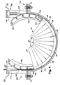
- FIG. 4 provides a simplified illustration of one embodiment of the present invention for removing a plurality of stator vane segments 50 installed in a casing slot.
- the apparatus 100 includes a compression device 110 adapted to apply a pushing force 115 on a rear surface 116 of the base 55 for a trailing stator vane segment 51; a clearing element 200 adapted to free adhesion materials 40 ( FIG. 2 ) holding the stator vane segments 50 within the slot 20 of the lower casing 10 of the gas turbine compressor; and a tension device 220 adapted to apply a pulling force 165 on a forward part 166 of the leading stator vane segment 53.
- the members transmitting the pushing force to the stator vane segment will be referred to as a compression train 130.
- the compression train 130 in the aforedescribed embodiment may include compression links and an impact link.
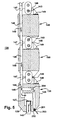
- FIG. 5 illustrates an internal cross-sectional view of the compression train.
- the compression train 130 may include an impact link 135 adapted to vibrate and push on a rear surface 116 of a trailing stator vane segment 51 within the casing slot 20; a compression unit 120 adapted to exert a backing force to allow the impact link 135 to vibrate against and push the trailing stator vane segment 51 through the casing slot 20; and a plurality of compression links 140, attached between the impact link 135 and the compression unit 120 ( FIG. 4 ) and adapted to transmit the backing force of the compression unit 120 to the impact link 136.
- Internal passages 148 within the impact link 135 and the compression links 140 provide for passage of high pressure gas flow, which may be high pressure air, from a source (not shown) outside the compressor casing through the impact head. Between links, the gas flow is provided through umbilicals 147.
- Pivot holes 143 at the ends of the compression links 140 accept pivot pins 125 for pivot links 145 to hold the links together when a compressive force is exerted. Pivoting by the pivot links 145 allows the compression train 130 to negotiate the curvature within the casing slot.
- FIG. 6 illustrates an embodiment of an impact link.
- the impact link 135 may include a body 136; an impact head 137 at a forward end 138 of the body 136; and a base 138 under the body 136, adapted to fit within the slot 20 of the lower casing 10 of the gas turbine compressor.
- the base 138 must also include a curved surface 134 matching that of the base for the stator vane segment 50 to allow rotational movement along the radius of casing slot 20.
- the base 138 may include a width 139 equivalent to the width of the base of the stator vane segment since the body must fit within the casing slot 20 between adjacent rotor blades and the dovetail 153 must conform to the grooves 30 of the casing slot 20 ( FIG.2 ), with tolerances to allow the impact link 135 to slide.
- the length 141 of the body 136 may be generally sized to approximately that of a stator vane segment.
- the impact head 137 is internal to the body 136 and at a forward end 138.
- the impact head 137 includes a striker 142 that may reciprocate from within the forward end 138.
- the striker 142 when in contact with the rear surface 116 of the trailing stator vane segment 51, applies a vibrating force to the rear surface 116.
- Means for communicating power to the impact head may be provided in multiple ways.
- the impact head 137 may be powered by high-pressure gas through gas flow path 148.
- the high-pressure gas may be supplied by umbilical 147 from outside the casing slot.
- the impact head 137 may be powered by an electric solenoid supplied by electric power through the umbilical 147.
- An alternate power method could also include ultrasonic or subsonic acoustics, supplied through the umbilical 147.
- a connecting element is provided at the rear end of the impact link.
- the connecting element may include a pivot link hole 143 (or other similar mechanism) on the rear surface 144 of the impact link 135 that may be provided to attach to an adjacent compression link 150, which transmits a backing force to maintain the impact head 137 in contact with the rear surface 116 of the trailing stator vane segment 51.
- Pivot links 145 may attach between the pivot link holes 143 in the impact link 135 and a corresponding pivot link hole 143 in the adjacent compression link 150, being attached with pivot pins 125.
- a force-transmitting pocket 149 may be provided on a rear surface 144. The force-transmitting pocket may accept a ram or other force-transmitting device from the compression unit 120 to exert itself by physical contact when the impact link 135 is in the compression unit 120.
- a clearing element 200 at a forward end 138 of the body 136 may include a nozzle 201.
- An internal passage 146 extending from a rear end 144 to a forward end 138 of the body 136 is adapted to communicate a high-pressure gas flow 148 to the high-pressure nozzle 201.
- the discharge 203 of the nozzle 202 directs the high-pressure gas 202 into the casing slot forward of the body.
- the discharged high-pressure gas 202 is forced between the outer surface 70 of the dovetail 65 of the trailing stator vane segment 51 and the inner surface 45 of the slot 20 of the lower casing 10 causing materials adhering 40 between the two surfaces to be freed and blown out of the slot ( FIG. 2 ).
- the impact head 137 is also powered by the high-pressure gas 202, the same high- pressure gas source and line may be provided for both uses.
- the high-pressure gas flow 204 may preferably be air.
- means may be provided for dispensing a penetrating lubricant, if so desired, to assist in freeing the stator vane segment from the casing slot.
- a penetrating lubricant could be provided from an outside source via umbilical 147 and communicated through the nozzle 202 and through the above-described passages in the impact link and connecting links or through a similar additional path.
- FIG. 7 illustrates an embodiment of a compression link.
- the compression link 150 includes a body 151 with a base 152 adapted to slide within the slot 20 of the lower casing of the gas turbine compressor a body.
- the base 152 will include a dovetail 153 to accommodate the groove 30 within the lower casing.
- the base 152 and dovetail 153 must also include curved surfaces 134 matching that of the trailing stator vane segment 51 to allow rotational movement along the radius of lower casing slot 20 ( FIG. 2 ).
- the body 151 may include a width 154 no wider than the width of the base of the stator vane segment since the body must fit within the space between adjacent rotor blades.
- the length of the body 151 may be sized preferably approximately that of the length of the stator vane segment.
- a first internal passage 146 from a rear end 159 to a forward end 158 of the body 151 may be adapted to communicate high-pressure gas flow path 148 through the compression link 150.
- the gas flow path 148 between adjacent compression links 150 may be provided by the umbilicals 147.
- the path for communicating high-pressure gas may be mounted external to the body, on the top of the body or on the side of the body.
- a second internal path or external path (not shown) may be provided for electric power, sonic power, etc. to the impact head 137 of the impact link 135 ( FIG. 6 ).
- These alternate paths may include brackets external to the body to hold tubing, hoses, or cables adapted to communicate power and/or high-pressure gas to the impact link 135.
- the body 151 of the connecting link 150 may also include a connecting element 156 at the forward end 157 and a connecting element 156 at the rear end 158, adapted to connect with compression links positioned forward and rearward.
- the connecting element 157 may include pivot link holes 143.
- Pivot links 145 may attach between pivot link holes 143 in the adjacent connecting links 150.
- the pivot links 159 maintain the compression train 130 between the adjacent connecting links 150 and transmit a backing force between individual compression links in a chain from the compression unit 120 to impact link 135.
- a force-transmitting pocket 149 may be provided on a rear end 159.
- the force-transmitting pocket 149 may accept a ram or other force-transmitting device from the compression unit 120 to exert itself by physical contact when the connecting link 145 is in the compression unit 120.
- a further embodiment of the compression link may comprise a modified stator vane segment, with the vanes removed.
- the modified stator vane segment already includes a base with a size and shape to accommodate fit and sliding within the lower casing slot.
- the stator vane segment may be further modified to provide internal paths or external paths for communicating power for the impact link and/or high-pressure gas for the cleaning nozzle on the impact link.
- the base on each modified stator vane segment will abut each other when in the lower casing slot, thereby allowing the backing force to be communicated through the bases of adjacent segments, and allowing the backing force to be transmitted to the impact link, which in this embodiment could include a flat face without a connecting device, since the stator vane segments are shaped to abut each other within the slot of the compressor casing.
- FIG. 8 illustrates one embodiment of a compression unit 120.
- the compression unit 120 may include a mounting fixture 121 adapted for mounting on the horizontal flange 15 of the lower half casing 10 above the slots 20 holding the stator vane segments (not shown) being extracted; a hydraulic ram 123; means for the hydraulic ram 123 to engage the pocket of rearmost compression link 150; means for engaging the connection links 150 from a compression link supply 126; means for inserting the connecting links 150 into the slot of the lower casing half; and a power source 127 adapted to supply the hydraulic ram 123.
- the compression unit 120 may include a flange 128 adapted for bolting to the horizontal casing flange 15 on the rear side of casing slot 20.
- a body 129 for the compression unit 120 may be mounted vertically with respect to the horizontal flange 15 of the compressor casing.
- the body 129 may be arranged as a hollow thick-walled box, centered above the entrance 90 to the slot 20 in the lower half casing 15.
- An interior side 194, with respect to the body 129, may include an opening 195 to accept a connecting train of compression connecting links.
- An exterior side 196 of the body may include safety access pins 197 to allow access the connecting links 150 within the body 129 for alignment or adjustment.
- a ram 123 with operating piston 124 may be mounted within an upper end of the body 129.
- the ram 198 may preferentially be hydraulically operated and include a connection 201 for an external hydraulic pressure source 202.
- the operating piston 124 is positioned within the body 129 to provide a stroke to a force-transmitting pocket 149 of the connecting link 150 and impact link 135, thereby asserting a backforce on the link residing within the body 129 of the compression unit 120 ( FIG. 4 ).
- the backforce is then transmitted through adjacent connecting links 150 in the slot 20 of the compressor casing 15 to supply the backforce to the impact link 135.
- the compression unit 120 may further include a link feed tray 208 mounted above the body 129 to allow for a smooth introduction of the compression train 130.
- a tension device 220 adapted to apply the pulling force 166 through tension train 160 to a forward part 166 of a leading stator vane segment 53, may include a tension unit 168, a tension cable 167 and a plurality of tension links 175.
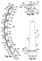
- FIG. 9A illustrates a tension train 160 of tension links 175 with tension cable 167.
- FIG. 9B illustrates a top view of the tension train 160 connected to the leading stator vane segment 53.
- FIG. 9C illustrates a side view of the tension train 160 connected to the leading stator vane segment 53.
- the tension cable 167 may be attached between the tension unit 168 ( FIG. 10 ) and the leading stator vane segment 53 and is adapted to transmit the pulling force 165 to the leading stator vane segment 53, up and out, through the slot 20 of the compressor lower casing 15.
- the tension cable 167 at the leading stator vane segment 53 may include a spring-loaded hook latch grapple 170.
- the spring-loaded hook latch grapple 170 may be pressed upon the front part 96 of leading stator vane 97 of the leading stator vane segment 53 being extracted.
- the spring-loaded hook latch ends 171, 172 bend outward when pressed against the front part 96 of the leading stator vane 97 until the latch ends 171, 172 fix around the back 98 of the leading stator vane 97.
- the tension cable 167 may also include a bead 173 that engages with a first tension link 186.
- a plurality of tension links 175 may be positioned between the tension unit 168 and the leading stator vane segment 53.
- the tension link 175 is adapted to position the tension cable 167 along a radial arc within the slot 20 of the lower half casing 15.
- the tension link 175 may be similarly configured in size and shape to the compression link, previously described. Therefore, like elements of the tension links and the compression links are similarly numbered.
- the tension link 175 may include a body 151; means 177 on each body for positioning the tension cable 167 in the radial arc of the slot 20 in the lower half casing 10; a base 152 with dovetail, adapted to fit within the dovetail groove 30 of the lower casing 10 of the gas turbine compressor; and pivot holes 143 at a forward end 158 and a rear end 159.
- a first internal path 181 from a forward end 158 to a rear end 159 of the body 176 may be adapted to pass the tension cable 167 through the tension link 175.
- a second internal path 182 from the forward end 158 to a rear end 159 of the body 176 may be adapted to pass an umbilical 183 for a camera 184 and forward lighting 185.
- the path for the tension cable may be mounted external to the body 176, on the top or side of the body 151.
- an alternate path for umbilical 183 may be mounted external to the body 151, on the top of the body.
- These alternate paths may include one or more brackets external to the body adapted to hold the tension cable 167 and umbilical 183.
- the first internal path 181 or external path maintains the tension cable 167 in a radial configuration through the radial arc of slot in the lower casing of the compressor so as to transfer the pulling force to the stator vane segment without binding on the inner surface of the casing slot 20.
- the first tension link 186 adjacent to the leading stator vane segment 53, may retain the end of the umbilical 183, including camera 184 and the forward lighting 185.
- the camera 184 and the forward lighting 185 may be positioned to provide a field of view to facilitate the spring-loaded hook latch 171, at the end of the tension cable 167, engaging with the leading vane 97 of the leading stator vane segment 53.
- the bead 173 on the tension cable 167 may engage with the rear end of the first tension link 186 to provide a pulling force on the tension train 164 during the extraction process.
- FIG. 10 illustrates an embodiment of a tension unit.
- the tension unit 168 includes a mounting fixture 188 adapted to mount the tension unit 168 on the horizontal flange 15 of the compressor lower casing 10; means for grasping and pulling the tension train 160; means for receiving and discharging the tension links 175 from the slot 20 of the compressor casing 10; and a power source 212 adapted to supply the tension unit.
- a body 195 of the tension unit 168 may be mounted vertically with respect to the horizontal flange 15.
- the body 195 may be arranged as a hollow thick-walled box, centered above the entrance 90 to the slot 20 in the lower half casing 10.
- An opening 90 in a the body 194 and positioned above the casing slot 20 may be provided to accept tension links 167 being extracted from the casing slot 20.
- An interior side 197 of the body 195 with respect to the lower casing may 10 include an opening 196 to accept the tension train 160 being extracted from the casing slot 20.
- An exterior side 198 of the body 194 may include removable safety access pins (not shown) to allow access to the tension train 160 within the body 195 for alignment or adjustment of travel through the body.
- ram 210 may be mounted.
- the ram 210 may preferentially be a single-acting hollow hydraulic ram (as known in the art) and include a connection 211 for an external power source 212, which for a hydraulic ram would be a hydraulic pressure source (as known in the art).
- a single acting hollow hydraulic ram 213 may include a split-collar, load-bearing device 214. The split-collar, load-bearing device 214 allows the tension cable 167 to feed through a center hole 215.
- stator vane segment As the pulling force moves the stator vane segment toward the tension unit, the tension links 175 are withdrawn from the slot 20 in the casing 10 and pass through the opening 196 of the body 195.
- the stator vane segment should be free by the time it arrives at the tension side horizontal joint. From there, once the last tension link is above the horizontal joint, the cable should be disconnected and the segment could be manually (by a service technicians hands) rolled out of the dovetail fit and removed.
- the tension unit may include other embodiments capable of applying a pulling force though a tension train to the stator vane segment.
- a further embodiment of the tension unit may include instead a chain fall, mounted above the opening to the exit side of the casing slot and adapted to attach to a tension cable, described above.
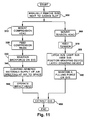
- FIG. 11 illustrates a flowchart of an embodiment of a method of extracting stator vane segments from a casing slot of a gas turbine compressor.
- the basic method includes applying a pushing force on the rear of the stator vane segment; clearing adhered materials between the stator vane segment and the casing slot; and applying a pulling force on the front side of the stator vane segment.
- step 300 an attempt may be made to manually remove a stator vane segments (SVS) next to the horizontal flange at the lower casing slot.
- the attempt may or may not be successful.
- a compression unit is mounted at an opening of a stator vane segment slot in a compressor casing.
- Step 320 feeds a compression train through the compression unit to abut the rear end of a trailing installed stator vane segment.
- the compression train may be assembled in advance including the impact link at the head, followed by a plurality of connecting links.
- the impact link and the connecting links connected in series with connecting devices include in one embodiment of an apparatus, pivot holes at the connecting ends of the link, joined together with pivot links.
- Step 330 maintains a backforce with the compression unit through the compression train apply the backforce to the trailing stator vane segment.
- Step 340 clears adhered material operating the clearing device by applying high-pressure air to the space between the base of the SVS and the internal surface of the casing slot.
- Step 350 operates an impact head to vibrate the stator vane segment, under the backforce from the compression unit.
- a tension unit is mounted at an opening of a stator vane segment slot in a compressor casing in step 360.
- Step 370 feeds a tension train of tension links carrying a tension cablethough the tension unit to abut a leading SVS.
- the leading SVS is latched with a means for grasping onto the vane of the leading SVS.
- the means may include a spring-loaded hook latch grapple where the spring-loaded hook latch is pressed upon the front of the leading vane of the leading SVS and latches around the back, allowing the leading vane to be used to pull the leading SVS. Forward lighting and a camera view may be used to assist in latching the leading SVS.
- a pulling force from the tension unit may be maintained on the leading SVS in step 390.
- the SVS are sequentially extracted through the tension unit.
Landscapes
- Engineering & Computer Science (AREA)
- Mechanical Engineering (AREA)
- General Engineering & Computer Science (AREA)
- Structures Of Non-Positive Displacement Pumps (AREA)
Abstract
Description
- The invention relates generally to a gas turbine compressor and more specifically to an apparatus and method for removing stator vane segments of a gas turbine compressor with the rotor for the gas turbine compressor in place.
- A conventional gas turbine generally operates on the principle of compressing air within a compressor and then delivering the compressed air to a combustion chamber where fuel is added to the air and ignited. Afterwards, the resulting combustion mixture is delivered to the turbine section of the gas turbine where a portion of the energy, generated by the combustion process, is extracted by a turbine to drive the compressor via a shaft.
- In multi-stage compressor sections, stators are placed at the entrance and exit of the compressor section, as well as between each compressor stage, for purposes of properly directing the airflow to each successive compressor stage. As a result, stators are able to enhance compressor performance by appropriately influencing airflow and pressure within the compressor section.
- Stators generally consist of an annular array of airfoils or vanes. Stators are typically formed in segments as stator vane segments consisting of one or more airfoils supported by the base. The base includes a dovetailed to maintain the stator vane unit within the casing. These stator vane segments are individually mounted to the compressor casing to form an annular array, so that the airfoils project radially between an adjacent pair of compressor stages. For this type of installation, a plurality of stator vane segments, with multiple blades, are assembled in the casing slot to form a stage.
-
FIG. 1 illustrates a top view of a lower-half casing for a compressor with the rotor removed, showing several individual casing slots for the assembly of stator vane stages.FIG. 2 illustrates a sectional view of a base of the stator vane segment within an individual casing slot. - The
casing 10 has a plurality ofslots 20 inhorizontal flanges 15 for receiving thestator vane segments 50. A first casing slot 21 is shown without the stator vane segment. Other casing slots 22 includestator vane segments 50 withvanes 60. Theslot 20 has a pair ofside edges 25, each of which has agroove 30 or dovetail-shaped recess. Thegroove 30 holds thestator vane segments 50 in place. Eachstator vane segment 50 is allowed to slide into place, with abase 55 being received in theslot 20 and thedovetail 60 being received in thegrooves 30. Thestator vane segments 50 for an individual stage are sequentially placed in theslot 20 of thecasing 10 until the full circumferential run of theslot 20 has been filled with a designated number ofstator vane segments 50. - When all stator vane slots for the casing are filled, a rotor with blades is mounted in the lower casing. The blades of the rotor occupy the space in the casing axially between the stator vanes. With the rotor in place, no access to the stator vanes is possible in an axial direction from either side. With the rotor in place and with the top half of the compressor casing removed, access is only available to the two stator vane segments, each positioned at one of the casing joints. However, direct access is not available to the other stator vane segments within slot of the lower casing half.
- During prolonged operation of the compressor, adhered
material 40, such as corrosion products and other foreign materials, may form in anarrow space 35 within thecasing slot 20 and between thecasing slot 20 and thedovetail 65 on thebase 55 of thestator vane segment 50. These adheredmaterials 40 may tend to bind thedovetail 65 for thebase 55 of thestator vane segments 50 to theinner surface 45 of thegroove 30 in thecasing slot 20, making removal of thestator vane segments 55 difficult. -
FIG. 3 illustrates an axial cutaway view of the compressor casing between stator stages with stator vane segments installed. Thecasing slot 20 is filled with a centerstator vane segment 80 and an outboardstator vane segment 85 to each side. Access may be available athorizontal flanges 15 to outboardstator vane segments 85, but access is limited to inboardstator vane segment 80. For other compressor stages and in other compressor arrangements more than one center stator vane segment may be installed. - No known device or method is available to remove the stator vane segments from the stator vane slots when the compressor rotor is mounted in the lower half of the casing. It has been necessary to lift and remove the compressor rotor from the lower casing, to expose stator vane segments and then manually apply a force to free and remove the stator vane segments. The need to remove the rotor of the compressor requires a heavy lift and adds additional manpower costs and delay time to the outage. Even with the rotor removed, the manual process remains difficult with restricted access between the stages of the stator vanes. The manual process requires slugging the stator vane segment with a leather covered hammer.
- Accordingly, there is a need to provide a safe and efficient apparatus and method for removing the stator vane segments of the gas turbine compressor with the rotor in place such that no damage results to the stator vane segments or the gas turbine compressor.
- During operation of rotating machine with stator vanes segments and rotating blades gas turbine compressor operation, a dovetailed base of stator vane segments may become fixed in a slot of the rotating machine casing due to corrosion products adhering to the dovetailed base and the inner surface of the slot. Access to the stator vane segments is limited when the upper casing half is removed, but the rotor for the rotating machine is still installed.
- Briefly in accordance with one aspect of the present invention, an apparatus is provided, adapted for removing a stator vane segment from a dovetailed slot in a lower casing of a rotating machine with stator vanes segments and rotating blades with an upper casing removed and the rotor in place is provided. The apparatus includes a compression device adapted to apply a pushing force on a rear surface of a stator vane segment. A clearing element is provided, which is adapted to free adhesion materials holding the stator vane segment to the dovetailed slot of the lower casing of the gas turbine compressor. A tension device is adapted to apply a pulling force to a forward surface of the stator vane segment.
- In another aspect of the present invention, a method is provided for extracting stator vane segments from a casing slot of a rotating machine with stator vanes segments and rotating blades. The steps include applying a pushing force on the rear of the stator vane segment; clearing adhered materials between the stator vane segment and the casing slot; and applying a pulling force on the front side of the stator vane segment.
- There follows a detailed description of embodiments of the invention by way of example only with reference to the accompanying drawings, in which:
-
FIG. 1 illustrates a top view of a lower-half casing for a compressor with the rotor removed, showing several individual casing slots for the assembly of stator vane stages; -
FIG. 2 illustrates a sectional view of a base of the stator vane segment within an individual casing slot; -
FIG. 3 illustrates an axial cutaway view of the compressor casing between stator stages with stator vane segments installed; -
FIG. 4 provides a simplified illustration of one embodiment of the present invention for removing a plurality of stator vane segments installed in a casing slot; -
FIG. 5 illustrates an embodiment of a compression train; -
FIG. 6 illustrates an embodiment of an impact link; -
FIG. 7 illustrates an embodiment of a compression link; -
FIG. 8 illustrates one embodiment of a compression unit; -
FIG. 8A illustrates an embodiment for a feeder device for the compression unit; -
FIG. 9A illustrates an embodiment for a tension train including tension links and a tension cable; -
FIG. 9B illustrates a top view of an embodiment of a tension train connection to the leading stator vane segment. -
FIG. 9C illustrates a side view of an embodiment of a tension train connection to the leading stator vane segment; -
FIG. 10 illustrates an embodiment of a tension unit; and -
FIG. 11 illustrates a flowchart for an embodiment of a method of extracting stator vane units from a casing slot of a compressor. - The following embodiments of the present invention have many advantages, including providing an apparatus and method to remove stator vane segments from the casing slots of a rotating machine with stator vanes segments and rotating blades without necessitating removal of the machine rotor. The rotating machine may be gas turbine compressor. Avoiding removal of the rotor for the machine saves considerable time and cost during the process. Avoiding removal of the rotor also reduces safety concerns and equipment damage associated with disassembly of unit and rotor removal.
- The present invention includes an embodiment of an apparatus adapted to facilitate removal of stator vane segments in a slot of a casing of a rotating machine with stator vanes segments and rotating blades. The machine may be a gas turbine compressor.
FIG. 4 provides a simplified illustration of one embodiment of the present invention for removing a plurality ofstator vane segments 50 installed in a casing slot. The apparatus 100 includes acompression device 110 adapted to apply a pushingforce 115 on arear surface 116 of thebase 55 for a trailingstator vane segment 51; aclearing element 200 adapted to free adhesion materials 40 (FIG. 2 ) holding thestator vane segments 50 within theslot 20 of thelower casing 10 of the gas turbine compressor; and atension device 220 adapted to apply a pullingforce 165 on a forward part 166 of the leadingstator vane segment 53. - The members transmitting the pushing force to the stator vane segment will be referred to as a
compression train 130. Thecompression train 130 in the aforedescribed embodiment may include compression links and an impact link. -
FIG. 5 illustrates an internal cross-sectional view of the compression train. Thecompression train 130 may include animpact link 135 adapted to vibrate and push on arear surface 116 of a trailingstator vane segment 51 within thecasing slot 20; acompression unit 120 adapted to exert a backing force to allow theimpact link 135 to vibrate against and push the trailingstator vane segment 51 through thecasing slot 20; and a plurality ofcompression links 140, attached between theimpact link 135 and the compression unit 120 (FIG. 4 ) and adapted to transmit the backing force of thecompression unit 120 to theimpact link 136.Internal passages 148 within theimpact link 135 and the compression links 140 provide for passage of high pressure gas flow, which may be high pressure air, from a source (not shown) outside the compressor casing through the impact head. Between links, the gas flow is provided throughumbilicals 147. Pivot holes 143 at the ends of the compression links 140 acceptpivot pins 125 forpivot links 145 to hold the links together when a compressive force is exerted. Pivoting by the pivot links 145 allows thecompression train 130 to negotiate the curvature within the casing slot. -
FIG. 6 illustrates an embodiment of an impact link. Theimpact link 135 may include abody 136; animpact head 137 at aforward end 138 of thebody 136; and abase 138 under thebody 136, adapted to fit within theslot 20 of thelower casing 10 of the gas turbine compressor. The base 138 must also include acurved surface 134 matching that of the base for thestator vane segment 50 to allow rotational movement along the radius ofcasing slot 20. The base 138 may include awidth 139 equivalent to the width of the base of the stator vane segment since the body must fit within thecasing slot 20 between adjacent rotor blades and thedovetail 153 must conform to thegrooves 30 of the casing slot 20 (FIG.2 ), with tolerances to allow theimpact link 135 to slide. Thelength 141 of thebody 136 may be generally sized to approximately that of a stator vane segment. - The
impact head 137, known in the art, is internal to thebody 136 and at aforward end 138. Theimpact head 137 includes astriker 142 that may reciprocate from within theforward end 138. Thestriker 142, when in contact with therear surface 116 of the trailingstator vane segment 51, applies a vibrating force to therear surface 116. Means for communicating power to the impact head may be provided in multiple ways. Theimpact head 137 may be powered by high-pressure gas throughgas flow path 148. The high-pressure gas may be supplied by umbilical 147 from outside the casing slot. Alternately, theimpact head 137 may be powered by an electric solenoid supplied by electric power through the umbilical 147. An alternate power method could also include ultrasonic or subsonic acoustics, supplied through the umbilical 147. - A connecting element is provided at the rear end of the impact link. The connecting element may include a pivot link hole 143 (or other similar mechanism) on the
rear surface 144 of theimpact link 135 that may be provided to attach to anadjacent compression link 150, which transmits a backing force to maintain theimpact head 137 in contact with therear surface 116 of the trailingstator vane segment 51. Pivot links 145 may attach between the pivot link holes 143 in theimpact link 135 and a correspondingpivot link hole 143 in theadjacent compression link 150, being attached with pivot pins 125. On arear surface 144, a force-transmittingpocket 149 may be provided. The force-transmitting pocket may accept a ram or other force-transmitting device from thecompression unit 120 to exert itself by physical contact when theimpact link 135 is in thecompression unit 120. - A
clearing element 200 at aforward end 138 of thebody 136 may include anozzle 201. Aninternal passage 146 extending from arear end 144 to aforward end 138 of thebody 136 is adapted to communicate a high-pressure gas flow 148 to the high-pressure nozzle 201. Thedischarge 203 of thenozzle 202 directs the high-pressure gas 202 into the casing slot forward of the body. The discharged high-pressure gas 202 is forced between the outer surface 70 of thedovetail 65 of the trailingstator vane segment 51 and theinner surface 45 of theslot 20 of thelower casing 10 causing materials adhering 40 between the two surfaces to be freed and blown out of the slot (FIG. 2 ). If theimpact head 137 is also powered by the high-pressure gas 202, the same high- pressure gas source and line may be provided for both uses. The high-pressure gas flow 204 may preferably be air. - Additionally, means may be provided for dispensing a penetrating lubricant, if so desired, to assist in freeing the stator vane segment from the casing slot. Such a penetrating lubricant could be provided from an outside source via umbilical 147 and communicated through the
nozzle 202 and through the above-described passages in the impact link and connecting links or through a similar additional path. -
FIG. 7 illustrates an embodiment of a compression link. Thecompression link 150 includes a body 151 with a base 152 adapted to slide within theslot 20 of the lower casing of the gas turbine compressor a body. Usually, thebase 152 will include adovetail 153 to accommodate thegroove 30 within the lower casing. Thebase 152 and dovetail 153 must also includecurved surfaces 134 matching that of the trailingstator vane segment 51 to allow rotational movement along the radius of lower casing slot 20 (FIG. 2 ). The body 151 may include awidth 154 no wider than the width of the base of the stator vane segment since the body must fit within the space between adjacent rotor blades. The length of the body 151 may be sized preferably approximately that of the length of the stator vane segment. - A first
internal passage 146 from arear end 159 to aforward end 158 of the body 151 may be adapted to communicate high-pressuregas flow path 148 through thecompression link 150. Thegas flow path 148 betweenadjacent compression links 150 may be provided by theumbilicals 147. Alternately, the path for communicating high-pressure gas may be mounted external to the body, on the top of the body or on the side of the body. A second internal path or external path (not shown) may be provided for electric power, sonic power, etc. to theimpact head 137 of the impact link 135 (FIG. 6 ). These alternate paths (not shown) may include brackets external to the body to hold tubing, hoses, or cables adapted to communicate power and/or high-pressure gas to theimpact link 135. - The body 151 of the connecting
link 150 may also include a connectingelement 156 at the forward end 157 and a connectingelement 156 at therear end 158, adapted to connect with compression links positioned forward and rearward. The connecting element 157 may include pivot link holes 143. Pivot links 145 may attach between pivot link holes 143 in the adjacent connectinglinks 150. The pivot links 159 maintain thecompression train 130 between the adjacent connectinglinks 150 and transmit a backing force between individual compression links in a chain from thecompression unit 120 toimpact link 135. - On a
rear end 159, a force-transmittingpocket 149 may be provided. The force-transmittingpocket 149 may accept a ram or other force-transmitting device from thecompression unit 120 to exert itself by physical contact when the connectinglink 145 is in thecompression unit 120. - A further embodiment of the compression link may comprise a modified stator vane segment, with the vanes removed. The modified stator vane segment already includes a base with a size and shape to accommodate fit and sliding within the lower casing slot. The stator vane segment may be further modified to provide internal paths or external paths for communicating power for the impact link and/or high-pressure gas for the cleaning nozzle on the impact link. The base on each modified stator vane segment will abut each other when in the lower casing slot, thereby allowing the backing force to be communicated through the bases of adjacent segments, and allowing the backing force to be transmitted to the impact link, which in this embodiment could include a flat face without a connecting device, since the stator vane segments are shaped to abut each other within the slot of the compressor casing.
-
FIG. 8 illustrates one embodiment of acompression unit 120. Thecompression unit 120 may include a mountingfixture 121 adapted for mounting on thehorizontal flange 15 of the lower half casing 10 above theslots 20 holding the stator vane segments (not shown) being extracted; ahydraulic ram 123; means for thehydraulic ram 123 to engage the pocket ofrearmost compression link 150; means for engaging the connection links 150 from a compression link supply 126; means for inserting the connectinglinks 150 into the slot of the lower casing half; and apower source 127 adapted to supply thehydraulic ram 123. - The
compression unit 120 may include aflange 128 adapted for bolting to thehorizontal casing flange 15 on the rear side ofcasing slot 20. Abody 129 for thecompression unit 120 may be mounted vertically with respect to thehorizontal flange 15 of the compressor casing. Thebody 129 may be arranged as a hollow thick-walled box, centered above theentrance 90 to theslot 20 in thelower half casing 15. An interior side 194, with respect to thebody 129, may include anopening 195 to accept a connecting train of compression connecting links. Anexterior side 196 of the body may include safety access pins 197 to allow access the connectinglinks 150 within thebody 129 for alignment or adjustment. Within an upper end of thebody 129, aram 123 withoperating piston 124 may be mounted. Theram 198 may preferentially be hydraulically operated and include aconnection 201 for an externalhydraulic pressure source 202. Theoperating piston 124 is positioned within thebody 129 to provide a stroke to a force-transmittingpocket 149 of the connectinglink 150 andimpact link 135, thereby asserting a backforce on the link residing within thebody 129 of the compression unit 120 (FIG. 4 ). The backforce is then transmitted through adjacent connectinglinks 150 in theslot 20 of thecompressor casing 15 to supply the backforce to theimpact link 135. - The
compression unit 120 may further include alink feed tray 208 mounted above thebody 129 to allow for a smooth introduction of thecompression train 130. - A
tension device 220, adapted to apply the pulling force 166 throughtension train 160 to a forward part 166 of a leadingstator vane segment 53, may include atension unit 168, atension cable 167 and a plurality of tension links 175. -
FIG. 9A illustrates atension train 160 oftension links 175 withtension cable 167.FIG. 9B illustrates a top view of thetension train 160 connected to the leadingstator vane segment 53.FIG. 9C illustrates a side view of thetension train 160 connected to the leadingstator vane segment 53. Thetension cable 167 may be attached between the tension unit 168 (FIG. 10 ) and the leadingstator vane segment 53 and is adapted to transmit the pullingforce 165 to the leadingstator vane segment 53, up and out, through theslot 20 of the compressorlower casing 15. Thetension cable 167 at the leadingstator vane segment 53 may include a spring-loaded hook latch grapple 170. During setup of thecompression train 160, the spring-loaded hook latch grapple 170 may be pressed upon thefront part 96 of leadingstator vane 97 of the leadingstator vane segment 53 being extracted. The spring-loaded hook latch ends 171, 172 bend outward when pressed against thefront part 96 of the leadingstator vane 97 until the latch ends 171, 172 fix around theback 98 of the leadingstator vane 97. Thetension cable 167 may also include abead 173 that engages with afirst tension link 186. - A plurality of
tension links 175 may be positioned between thetension unit 168 and the leadingstator vane segment 53. Thetension link 175 is adapted to position thetension cable 167 along a radial arc within theslot 20 of thelower half casing 15. Thetension link 175 may be similarly configured in size and shape to the compression link, previously described. Therefore, like elements of the tension links and the compression links are similarly numbered. Thetension link 175 may include a body 151; means 177 on each body for positioning thetension cable 167 in the radial arc of theslot 20 in thelower half casing 10; a base 152 with dovetail, adapted to fit within thedovetail groove 30 of thelower casing 10 of the gas turbine compressor; and pivotholes 143 at aforward end 158 and arear end 159. - A first
internal path 181 from aforward end 158 to arear end 159 of the body 176 may be adapted to pass thetension cable 167 through thetension link 175. A secondinternal path 182 from theforward end 158 to arear end 159 of the body 176 may be adapted to pass an umbilical 183 for acamera 184 andforward lighting 185. Alternatively, the path for the tension cable may be mounted external to the body 176, on the top or side of the body 151. Similarly an alternate path for umbilical 183 may be mounted external to the body 151, on the top of the body. These alternate paths may include one or more brackets external to the body adapted to hold thetension cable 167 and umbilical 183. The firstinternal path 181 or external path maintains thetension cable 167 in a radial configuration through the radial arc of slot in the lower casing of the compressor so as to transfer the pulling force to the stator vane segment without binding on the inner surface of thecasing slot 20. - The
first tension link 186, adjacent to the leadingstator vane segment 53, may retain the end of the umbilical 183, includingcamera 184 and theforward lighting 185. Thecamera 184 and theforward lighting 185 may be positioned to provide a field of view to facilitate the spring-loadedhook latch 171, at the end of thetension cable 167, engaging with the leadingvane 97 of the leadingstator vane segment 53. Further, thebead 173 on thetension cable 167 may engage with the rear end of thefirst tension link 186 to provide a pulling force on the tension train 164 during the extraction process. -
FIG. 10 illustrates an embodiment of a tension unit. Thetension unit 168 includes a mountingfixture 188 adapted to mount thetension unit 168 on thehorizontal flange 15 of the compressorlower casing 10; means for grasping and pulling thetension train 160; means for receiving and discharging the tension links 175 from theslot 20 of thecompressor casing 10; and apower source 212 adapted to supply the tension unit. - A
body 195 of thetension unit 168 may be mounted vertically with respect to thehorizontal flange 15. Thebody 195 may be arranged as a hollow thick-walled box, centered above theentrance 90 to theslot 20 in thelower half casing 10. Anopening 90 in a the body 194 and positioned above thecasing slot 20 may be provided to accepttension links 167 being extracted from thecasing slot 20. Aninterior side 197 of thebody 195 with respect to the lower casing may 10 include anopening 196 to accept thetension train 160 being extracted from thecasing slot 20. Anexterior side 198 of the body 194 may include removable safety access pins (not shown) to allow access to thetension train 160 within thebody 195 for alignment or adjustment of travel through the body. - Within an upper end of the body 164, means for grasping and pulling 213 the
tension train 160 is provided. Here,ram 210 may be mounted. Theram 210 may preferentially be a single-acting hollow hydraulic ram (as known in the art) and include aconnection 211 for anexternal power source 212, which for a hydraulic ram would be a hydraulic pressure source (as known in the art). A single acting hollowhydraulic ram 213 may include a split-collar, load-bearing device 214. The split-collar, load-bearing device 214 allows thetension cable 167 to feed through acenter hole 215. The single actinghydraulic ram 213, when operating in response to thepressure source 212, compresses the split-collar load-bearing device 214 on thetension cable 167 and extends the split-collar, load-bearing device 214 upward, thereby applying a pulling force to a leadingstator vane segment 53. - As the pulling force moves the stator vane segment toward the tension unit, the tension links 175 are withdrawn from the
slot 20 in thecasing 10 and pass through theopening 196 of thebody 195. The stator vane segment should be free by the time it arrives at the tension side horizontal joint. From there, once the last tension link is above the horizontal joint, the cable should be disconnected and the segment could be manually (by a service technicians hands) rolled out of the dovetail fit and removed. - The tension unit may include other embodiments capable of applying a pulling force though a tension train to the stator vane segment. For example, a further embodiment of the tension unit may include instead a chain fall, mounted above the opening to the exit side of the casing slot and adapted to attach to a tension cable, described above.
- According to another aspect of the present invention, a method is provided for extracting stator vane segments from a casing slot of a gas turbine compressor.
FIG. 11 illustrates a flowchart of an embodiment of a method of extracting stator vane segments from a casing slot of a gas turbine compressor. The basic method includes applying a pushing force on the rear of the stator vane segment; clearing adhered materials between the stator vane segment and the casing slot; and applying a pulling force on the front side of the stator vane segment. - Initially, in step 300, an attempt may be made to manually remove a stator vane segments (SVS) next to the horizontal flange at the lower casing slot. The attempt may or may not be successful.
- According to step 310 a compression unit is mounted at an opening of a stator vane segment slot in a compressor casing. Step 320 feeds a compression train through the compression unit to abut the rear end of a trailing installed stator vane segment. The compression train may be assembled in advance including the impact link at the head, followed by a plurality of connecting links. The impact link and the connecting links connected in series with connecting devices include in one embodiment of an apparatus, pivot holes at the connecting ends of the link, joined together with pivot links. Step 330 maintains a backforce with the compression unit through the compression train apply the backforce to the trailing stator vane segment. Step 340 clears adhered material operating the clearing device by applying high-pressure air to the space between the base of the SVS and the internal surface of the casing slot. Step 350 operates an impact head to vibrate the stator vane segment, under the backforce from the compression unit.
- In parallel with the application of the vibration and pushing force, described above, a tension unit is mounted at an opening of a stator vane segment slot in a compressor casing in
step 360. Step 370 feeds a tension train of tension links carrying a tension cablethough the tension unit to abut a leading SVS. Instep 380, the leading SVS is latched with a means for grasping onto the vane of the leading SVS. The means may include a spring-loaded hook latch grapple where the spring-loaded hook latch is pressed upon the front of the leading vane of the leading SVS and latches around the back, allowing the leading vane to be used to pull the leading SVS. Forward lighting and a camera view may be used to assist in latching the leading SVS. - A pulling force from the tension unit may be maintained on the leading SVS in step 390. In
step 400, the SVS are sequentially extracted through the tension unit. - While various embodiments are described herein, it will be appreciated from the specification that various combinations of elements, variations or improvements therein may be made, and are within the scope of the invention.
- For completeness, various aspects of the invention are now set out in the following numbered clauses:
- 1. An apparatus adapted for removing a stator vane segment from a dovetailed slot in a lower casing of a rotating machine with stator vanes segments and rotating blades with an upper casing removed and the rotor in place, comprising:
- a compression device adapted to apply a pushing force on a rear surface of a stator vane segment;
- a clearing element adapted to free adhesion materials holding the stator vane segment to a dovetailed slot of the lower casing of the gas turbine compressor; and
- a tension device adapted to apply a pulling force to a forward surface of the stator vane segment.
- 2. The apparatus apparatus adapted for removing a stator vane segment according to clause 1, wherein the compression device comprises:
- an impact link adapted to vibrate and push on a back surface of a stator vane segment within the dovetailed slot;
- a compression unit adapted to exert a backing force to allow the impact link to vibrate and push the stator vane segment through the dovetailed slot; and
- a plurality of compression links, attached between the impact link and the compression unit in the casing slot and adapted to transmit the backing force of the compression unit to the impact link.
- 3. The apparatus adapted for removing a stator vane segment according to clause 2, wherein the impact link comprises:
- a body;
- an impact head at a forward end of the body;
- means for communicating power to the impact head through the body;
- means for communciating high pressure gas to the cleaning element at a forward end of the body; and
- a dovetailed base under the body, adapted to slide within the dovetailed slot of the lower casing of the gas turbine compressor.
- 4. The apparatus adapted for removing a stator vane segment according to clause 3, wherein means for communicating high pressure gas to the cleaning element at the forward end of the body further comprises means to deliver a lubricant to the cleaning element at the forward end of the body.
- 5. The apparatus adapted for removing a stator vane segment according to clause 3, the impact link further comprises:
- a connecting element at the rear end of the body; and
- a pocket on a rear surface, adapted to receive a backing force.
- 6. The apparatus adapted for removing a stator vane segment according to clause 3, the impact link further comprises:
- the clearing element including a nozzle at a forward end of the body; and
- a gas path from a rear end to a forward end of the body adapted to communicate a pressurized gas to the nozzle.
- 7. The apparatus adapted for removing a stator vane segment according to clause 3, the means to communicate drive power comprises: at least one of a high pressurized gas path and an electric power path to the impact head.
- 8. The apparatus adapted for removing a stator vane segment according to clause 2, wherein the plurality of compression links comprise:
- a body;
- at least one of a path for a power and a path for a pressurized gas from a rear end to a forward end of the compression link; and
- a dovetailed base adapted to fit within the dovetailed slot of the lower casing of the gas turbine compressor.
- 9. The apparatus adapted for removing a stator vane segment according to clause 2, wherein the plurality of compression links further comprise:
- means for connecting at the forward end;
- means for connecting at the rear end; and
- a pocket on a rear surface adapted to receive a backing force from the compression unit.
- 10. The apparatus adapted for removing a stator vane segment according to clause 7, wherein the plurality of compression links further comprise:
- a modified stator vane segment.
- 11. The apparatus adapted for removing a stator vane segment according to clause 2, the compression unit comprising:
- a mounting fixture adapted to mount the tension unit on the flange of the lower half casing in the rear of the stator vane segment being extracted;
- a ram;
- means for the ram engaging the pocket of the compression links;
- means for inserting the plurality of compression links into the the slot of the lower casing half; and
- a power source adapted to supply power to the ram.
- 12. The apparatus adapted for removing a stator vane segment according to clause 1, the tension device comprising:
- a tension unit adapted to exert a force pulling a leading stator vane segment through the dovetailed slot of the lower casing;
- a tension cable, attached between the tension unit and the leading stator vane segment, and adapted to transmit the pulling force of the tension unit to the stator vane segment;
- a plurality of tension links, positioned between the tension unit and the the stator vane segment and adapted to position the tension cable along a radial arc within the slot of the lower half casing.
- 13. The apparatus adapted for removing a stator vane segment according to clause 12, wherein the plurality of tension links comprise:
- a body;
- means on each body for positioning the tension cable in a radial arc of the slot in the lower half casing;
- a connecting element at the forward end;
- a connecting element at the rear end; and
- a dovetailed base adapted to fit within the dovetailed slot of the lower casing of the gas turbine compressor.
- 14. The apparatus adapted for removing a stator vane segment according to clause 11, wherein the tension cable comprises: means at a forward end for latching onto the vanes of the stator vane segment.
- 15. The apparatus adapted for removing a stator vane segment according to clause 11, the tension unit comprising:
- a mounting fixture adapted to mount the tension unit on the flange of the lower half casing;
- means for grasping the tension cable;
- means for pulling the tension cable;
- means for receiving and discharging the tension links from the slot of the lower casing half; and
- a power source adapted to supply the tension unit.
- 16. The apparatus apparatus adapted for removing a stator vane segment according to clause 1, wherein the rotating machine comprises: a gas turbine compressor.
- 17. A method for removing a stator vane segment from a dovetailed slot in a lower casing of a rotating machine with stator vanes segments and rotating blades with an upper casing removed and the rotor in place, comprising:
- applying a pushing force on a rear side of the stator vane segment;
- clearing adhered materials between the stator vane segment and the casing slot; and applying a pulling force on a front side of the stator vane segment.
- 18. The method for removing a stator vane segment according to clause 17, the step of applying a pushing force comprising:
- mounting a compression unit at an opening of a stator vane segment slot in a compressor casing;
- feeding a compression train through the compression unit to abut an installed stator vane segment;
- maintaining a pushing force with the compression unit through the compression train to the stator vane segment; and
- operating an impact head to vibrate the stator vane segment.
- 19. The method for removing a stator vane segment according to clause 17, the step of applying a pulling force comprising:
- mounting a tension unit at an opening of a stator vane segment slot in a compressor casing;
- feeding a tension train though the tension unit to abut an installed stator vane segment;
- grasping a forward end of the stator vane segment by the tension train; and
- applying a pulling force with the tension unit.
- 20. The method for removing a stator vane segment according to clause 19, the step of grasping a forward end of the stator vane segment comprising:
- latching a grasping device onto a forward vane of the stator vane segment.
- 21. The method for removing a stator vane segment according to
clause 20, the step of latching a grasping device comprising:- lighting the forward end of the stator vane segment;
- viewing the forward end of the stator vane segment; and
- positioning the grasping device to latch spring loaded arms of the grasping device over the forward vane of the stator vane segment.
- 22. The method for removing a stator vane segment according to clause 17, the step of clearing adhered materials comprising:
- supplying a pressurized gas to a nozzle of the cleaning element; and
- directing the pressurized gas to a space between a dovetailed of the stator vane segment and the inner surface of the casing slot.
- 23. The method for removing a stator vane segment according to clause 17, further comprising:
- attempting to remove a stator vane segment adjacent to an opening for the stator vane segment slot on each side of the compressor casing by manual means.
- 24. The method for removing a stator vane segment according to clause 17, wherein the rotating machine comprises: a gas turbine compressor.
Claims (15)
- An apparatus (100) adapted for removing a stator vane segment (50) from a casing slot (20) in a lower casing (10) of a rotating machine (5) with stator vanes segments and rotating blades with an upper casing removed and the rotor in place, the apparatus comprising:a compression device (110) adapted to apply a pushing force (185) on a trailing stator vane segment (51);a clearing element (200) adapted to free adhesion materials 40 holding the stator vane segment (50) to a casing slot (20) of the lower casing (10) of the rotating machine (5); anda tension device (220) adapted to apply a pulling force (165) to a leading stator vane segment (53).
- The apparatus (100) according to claim 1, wherein the compression device (110) comprises:an impact link (135) adapted to vibrate and push on the trailing stator vane segment (51) within the casing slot (20);a compression unit (120) adapted to exert a backing force (115) to allow the impact link to vibrate and push the traling stator vane segment (51) through the casing slot (20); anda plurality of compression links (150), attached between the impact link (135) and the compression unit (120) in the casing slot (20) and adapted to transmit the backing force (115) of the compression unit (120) to the impact link (135).
- The apparatus (100) according to claim 2, wherein the impact link (135) comprises:a body (136);an impact head (137) of the body (136);a nozzle (202) of the clearing element (200);means for communicating power (148) to the impact head (137) through the body (136);means for communcating high pressure gas (204) to the nozzle (202) of clearing element (200);a casing base (152) of the body (136), adapted to slide within the casing slot (20) of the lower casing (10) of the rotating machine (5);a connecting element (156) for the body (136); anda pocket (149) adapted to receive the backing force (115).
- The apparatus (100) according to claim 3, wherein the means to communicate drive power comprising:a path (148) to the impact head (137) for at least one of a high pressurized gas and electric power.
- The apparatus (100) according to claim 2, wherein the plurality of compression links (150) comprise:a body (151);a path (148) for at least one of power and pressurized gas from a rear end through the compression link (150);a dovetailed base adapted to ride within the casing slot (20) of the lower casing (10) of the rotating machine;means for connecting (156) at the forward end of the body;means for connecting (156) the body (136) to adjacent links; and a pocket (149) adapted to receive a backing force (115) from the compression unit (120).
- The apparatus (100) according to claim 5, wherein the plurality of compression links (150) further comprise:a modified stator vane segment (50).
- The apparatus (100) according to claim 2, wherein the compression unit (120) comprises:a mounting fixture adapted to mount the tension unit on the flange of the lower half casing in the rear of the stator vane segment being extracted;a ram (123);means for the ram engaging (124) the pocket (149) of the compression links (150);means for inserting the plurality of compression links (150) into the the casing slot (20) of the lower casing half (10); anda power source (127) adapted to supply power to the ram (123).
- The apparatus (100) according to any of the preceding claims, wherein the tension device (220) comprises:a tension unit (168) adapted to exert a force (165) for pulling a leading stator vane segment (51) through the casing slot (20) of the lower casing (10);a tension cable (167), attached between the tension unit (168) and the leading stator vane segment (51), and adapted to transmit the pulling force (165) of the tension unit (168) to the leading stator vane segment (51) by latching means (170);a plurality of tension links (175), positioned between the tension unit (168) and the leading stator vane segment (51) and adapted to position the tension cable (167) along a radial arc within the slot (20) of the lower half casing (10).
- The apparatus (100) according to claim 8, wherein the plurality of tension links (175) comprise:a body (151);means on each body for positioning the tension cable (167) in a radial arc of the casing slot (20) in the lower half casing (10) of the rotating machine (5);a connecting elements (145) adapted for connection to other tension links (175); and a base (152) adapted to fit within the casing slot (20) of the lower casing (10) of the rotating machine (5).
- The apparatus (100) according to claim 9, wherein the tension unit (168) comprises:a mounting fixture (188) adapted to mount the tension unit (168) to the flange (15) of the lower half casing (10);means for grasping (214) the tension cable (167);means for pulling (214) the tension cable (167);means for receiving and discharging the tension links (175) from the casing slot (20) of the lower casing half (10) of the rotating machine (5); anda power source (212) adapted to supply the tension unit (168).
- A method for removing a stator vane segment from a dovetailed slot in a lower casing of a rotating machine with stator vanes segments and rotating blades with an upper casing removed and the rotor in place, comprising:applying a pushing force on a rear side of the stator vane segment;clearing adhered materials between the stator vane segment and the casing slot; andapplying a pulling force on a front side of the stator vane segment.
- The method according to claim 11, wherein the step of applying a pushing force comprises:mounting a compression unit at an opening of a stator vane segment slot in a compressor casing;feeding a compression train through the compression unit to abut an installed stator vane segment;maintaining a pushing force with the compression unit through the compression train to the stator vane segment; andoperating an impact head to vibrate the stator vane segment.
- The method according to claim 17, wherein the step of applying a pulling force comprises:mounting a tension unit at an opening of a stator vane segment slot in a compressor casing;feeding a tension train though the tension unit to abut an installed stator vane segment;grasping a forward end of the stator vane segment by the tension train; and applying a pulling force with the tension unit.
- The method according to claim 13, wherein the step of grasping a forward end of the stator vane segment comprises:latching a grasping device onto a forward vane of the stator vane segment.
- The method according to claim 14, wherein the step of latching a grasping device comprises:lighting the forward end of the stator vane segment;viewing the forward end of the stator vane segment; andpositioning the grasping device to latch spring loaded arms of the grasping device over the forward vane of the stator vane segment.
Applications Claiming Priority (1)
| Application Number | Priority Date | Filing Date | Title |
|---|---|---|---|
| US12/236,930 US8117727B2 (en) | 2008-09-24 | 2008-09-24 | Apparatus and method for removing gas turbine compressor stator vane segments with rotor in place |
Publications (3)
| Publication Number | Publication Date |
|---|---|
| EP2169184A2 true EP2169184A2 (en) | 2010-03-31 |
| EP2169184A3 EP2169184A3 (en) | 2013-04-24 |
| EP2169184B1 EP2169184B1 (en) | 2014-11-12 |
Family
ID=41559458
Family Applications (1)
| Application Number | Title | Priority Date | Filing Date |
|---|---|---|---|
| EP09170403.1A Active EP2169184B1 (en) | 2008-09-24 | 2009-09-16 | Apparatus and method for removing gas turbine compressor stator vane segments with rotor in place |
Country Status (4)
| Country | Link |
|---|---|
| US (1) | US8117727B2 (en) |
| EP (1) | EP2169184B1 (en) |
| JP (1) | JP2010077966A (en) |
| CN (1) | CN101684813B (en) |
Cited By (4)
| Publication number | Priority date | Publication date | Assignee | Title |
|---|---|---|---|---|
| EP2851522A1 (en) * | 2013-09-19 | 2015-03-25 | Siemens Aktiengesellschaft | Rotation device for a gas turbine and processes for rotating an element |
| WO2015084194A1 (en) * | 2013-12-05 | 2015-06-11 | General Electric Company | Turbine shroud block removal apparatus |
| US9512722B2 (en) | 2013-07-30 | 2016-12-06 | Rolls-Royce Plc | Aerofoil component handling tool |
| CN108474264A (en) * | 2016-01-13 | 2018-08-31 | 三菱日立电力系统株式会社 | Blade removal device and method |
Families Citing this family (20)
| Publication number | Priority date | Publication date | Assignee | Title |
|---|---|---|---|---|
| US8381379B2 (en) * | 2009-04-17 | 2013-02-26 | General Electric Company | Apparatus and tools for use with compressors |
| GB2489003B8 (en) * | 2011-03-15 | 2013-08-07 | Rolls Royce Plc | Method and apparatus for removing an aerofoil structure from a casing section of a rotary machine |
| US8757962B2 (en) * | 2011-06-16 | 2014-06-24 | General Electric Company | System and method for adjusting a shroud block in a casing |
| US9260978B2 (en) | 2012-03-19 | 2016-02-16 | General Electric Company | System and method for heating a stator segment |
| US9097123B2 (en) * | 2012-07-26 | 2015-08-04 | General Electric Company | Method and system for assembling and disassembling turbomachines |
| EP2706199B1 (en) * | 2012-09-10 | 2018-12-12 | Ansaldo Energia Switzerland AG | Method and guide for removing an inner casing from a turbomachine |
| JP6082285B2 (en) * | 2013-03-14 | 2017-02-15 | 三菱日立パワーシステムズ株式会社 | Method for removing / attaching stator blade ring, and auxiliary support device for stator blade segment used in this method |
| JP6238056B2 (en) * | 2013-11-26 | 2017-11-29 | 三菱日立パワーシステムズ株式会社 | Dummy ring assembly for removing a vane segment and a method for removing a vane segment using the same |
| US9382801B2 (en) | 2014-02-26 | 2016-07-05 | General Electric Company | Method for removing a rotor bucket from a turbomachine rotor wheel |
| US9429041B2 (en) * | 2014-05-14 | 2016-08-30 | General Electric Company | Turbomachine component displacement apparatus and method of use |
| US9587498B2 (en) * | 2014-12-03 | 2017-03-07 | General Electric Company | System and method for removing stator vanes from a casing of a rotary machine |
| JP6547534B2 (en) * | 2015-09-14 | 2019-07-24 | 株式会社Ihi | Axial flow machine disassembly method |
| US10273814B2 (en) | 2016-01-05 | 2019-04-30 | General Electric Company | Tool and method for installing turbomachine component |
| US10265838B2 (en) | 2016-03-28 | 2019-04-23 | General Electric Company | Removal tool |
| JP6236494B2 (en) * | 2016-05-19 | 2017-11-22 | 太平電業株式会社 | Method and apparatus for removing stationary blade segment for rotating equipment |
| US10472990B2 (en) * | 2016-11-08 | 2019-11-12 | General Electric Company | Nozzle maintenance apparatus and method |
| CN108005732B (en) * | 2017-12-20 | 2024-04-19 | 华瑞(江苏)燃机服务有限公司 | Dismounting mechanism of turbine stationary blade assembly of gas turbine |
| DE102018114093A1 (en) * | 2018-06-13 | 2019-12-19 | Man Energy Solutions Se | Burst protection device for a gas turbine engine |
| CN108907665B (en) * | 2018-07-27 | 2020-06-16 | 淮南国力液压装备有限公司 | Cylinder drawing machine for upright column |
| KR102491290B1 (en) * | 2018-08-17 | 2023-01-27 | 미츠비시 파워 가부시키가이샤 | Position adjustment method and position adjustment jig of arc-shaped member |
Family Cites Families (13)
| Publication number | Priority date | Publication date | Assignee | Title |
|---|---|---|---|---|
| US3673668A (en) * | 1970-08-31 | 1972-07-04 | Ind Solvers Inc | Vane ejector tool |
| DE2152365C3 (en) * | 1971-02-03 | 1973-12-06 | Carrier Corp., Syracuse, N.Y. (V.St.A.) | Device for supporting the inner ends of rotatably mounted guide vanes of an axial flow machine |
| FR2282550A1 (en) * | 1974-08-21 | 1976-03-19 | Shur Lok International Sa | MONOBLOC CASING COMPRESSOR STATOR |
| US4096614A (en) * | 1975-09-02 | 1978-06-27 | General Electric Company | Method and apparatus for removing stator vanes |
| US4078290A (en) * | 1976-11-08 | 1978-03-14 | Nasa | Stator rotor tools |
| US4455730A (en) * | 1982-08-30 | 1984-06-26 | Westinghouse Electric Corp. | Turbine blade extractor |
| US4805282A (en) * | 1986-08-14 | 1989-02-21 | Amoco Corporation | Process for revamping the stator blades of a gas turbine |
| RU2246651C2 (en) * | 2000-03-22 | 2005-02-20 | Сименс Акциенгезелльшафт | Method of removing seal |
| DE10020229A1 (en) * | 2000-04-25 | 2001-10-31 | Alstom Power Nv | Method and device for dismantling a turbine blade |
| JP4562931B2 (en) * | 2001-02-19 | 2010-10-13 | 三菱重工業株式会社 | Stator blade assembly and fluid-operated rotating machine having the stator blade assembly |
| ES2346874T3 (en) * | 2004-07-09 | 2010-10-21 | Siemens Aktiengesellschaft | DEVICE FOR DISASSEMBLY OF SHOVELS FROM A TURBINE OR A COMPRESSOR. |
| US7743497B2 (en) * | 2005-10-06 | 2010-06-29 | General Electric Company | Method of providing non-uniform stator vane spacing in a compressor |
| US8677591B2 (en) * | 2008-04-28 | 2014-03-25 | General Electric Company | Methods and system for disassembling a machine |
-
2008
- 2008-09-24 US US12/236,930 patent/US8117727B2/en active Active
-
2009
- 2009-09-16 EP EP09170403.1A patent/EP2169184B1/en active Active
- 2009-09-17 JP JP2009215219A patent/JP2010077966A/en active Pending
- 2009-09-24 CN CN200910205656.6A patent/CN101684813B/en active Active
Cited By (9)
| Publication number | Priority date | Publication date | Assignee | Title |
|---|---|---|---|---|
| US9512722B2 (en) | 2013-07-30 | 2016-12-06 | Rolls-Royce Plc | Aerofoil component handling tool |
| EP2851522A1 (en) * | 2013-09-19 | 2015-03-25 | Siemens Aktiengesellschaft | Rotation device for a gas turbine and processes for rotating an element |
| WO2015039830A1 (en) | 2013-09-19 | 2015-03-26 | Siemens Aktiengesellschaft | Rotating device for a gas turbine and method for rotating a component |
| US10711651B2 (en) | 2013-09-19 | 2020-07-14 | Siemens Aktiengesellschaft | Rotating device for a gas turbine and method for rotating a component |
| WO2015084194A1 (en) * | 2013-12-05 | 2015-06-11 | General Electric Company | Turbine shroud block removal apparatus |
| US9816398B2 (en) | 2013-12-05 | 2017-11-14 | General Electric Company | Turbine shroud block removal apparatus |
| CN108474264A (en) * | 2016-01-13 | 2018-08-31 | 三菱日立电力系统株式会社 | Blade removal device and method |
| CN108474264B (en) * | 2016-01-13 | 2020-10-09 | 三菱日立电力系统株式会社 | Blade extraction device and method |
| US10954791B2 (en) | 2016-01-13 | 2021-03-23 | Mitsubishi Power, Ltd. | Blade removal device and method |
Also Published As
| Publication number | Publication date |
|---|---|
| CN101684813B (en) | 2014-12-03 |
| JP2010077966A (en) | 2010-04-08 |
| CN101684813A (en) | 2010-03-31 |
| US20100071183A1 (en) | 2010-03-25 |
| EP2169184B1 (en) | 2014-11-12 |
| US8117727B2 (en) | 2012-02-21 |
| EP2169184A3 (en) | 2013-04-24 |
Similar Documents
| Publication | Publication Date | Title |
|---|---|---|
| EP2169184B1 (en) | Apparatus and method for removing gas turbine compressor stator vane segments with rotor in place | |
| CN101947727B (en) | Apparatus and method for removing compressor blades | |
| US8381379B2 (en) | Apparatus and tools for use with compressors | |
| JP6259480B2 (en) | Accessory device and method of assembling accessory to turbine engine | |
| US4096614A (en) | Method and apparatus for removing stator vanes | |
| CN101905454B (en) | Remove or the method and apparatus of install combustion lining | |
| EP3327250B1 (en) | Installation or removal of turbine blade at turbine blade base | |
| EP3318716B1 (en) | Installation or removal of turbine blade at turbine blade base | |
| EP1207272B1 (en) | Replaceable variable stator vane for gas turbines | |
| US20220325825A1 (en) | System and method for extracting a buried pipe | |
| CA2957448C (en) | System and method for in situ repair of turbine blades of gas turbine engines | |
| KR101169040B1 (en) | A device for extending and replacing pipe comprising growing and crushing portion and method using the same | |
| CN117260620B (en) | A blade removal tool and method | |
| CN109577880A (en) | A kind of propulsion device and drilling machine with boring coring function | |
| CN1022363C (en) | Rotor retaining ring system | |
| US6622381B2 (en) | Method of manipulating a pump | |
| JP6205058B2 (en) | Turbine shroud block removal device | |
| JP2011045992A (en) | Apparatus and tools for use with compressor | |
| US10598306B2 (en) | Method and apparatus for replacing underground pipe | |
| SE445059B (en) | GAS TURBINE | |
| KR20200113418A (en) | Jig for testing blade | |
| CN106413938B (en) | For driving the hydraulic vibration tool of conveyer belt fastener rivet | |
| GB2186899A (en) | Installing pipes in the ground | |
| CN210189659U (en) | Special tool for rapidly disassembling and connecting overhead chain | |
| RU2221181C2 (en) | Device for trenchless replacement of pipelines |
Legal Events
| Date | Code | Title | Description |
|---|---|---|---|
| PUAI | Public reference made under article 153(3) epc to a published international application that has entered the european phase |
Free format text: ORIGINAL CODE: 0009012 |
|
| AK | Designated contracting states |
Kind code of ref document: A2 Designated state(s): AT BE BG CH CY CZ DE DK EE ES FI FR GB GR HR HU IE IS IT LI LT LU LV MC MK MT NL NO PL PT RO SE SI SK SM TR |
|
| PUAL | Search report despatched |
Free format text: ORIGINAL CODE: 0009013 |
|
| AK | Designated contracting states |
Kind code of ref document: A3 Designated state(s): AT BE BG CH CY CZ DE DK EE ES FI FR GB GR HR HU IE IS IT LI LT LU LV MC MK MT NL NO PL PT RO SE SI SK SM TR |
|
| RIC1 | Information provided on ipc code assigned before grant |
Ipc: F01D 9/04 20060101AFI20130319BHEP Ipc: B23P 6/00 20060101ALI20130319BHEP Ipc: F01D 25/28 20060101ALI20130319BHEP Ipc: B23P 19/02 20060101ALI20130319BHEP |
|
| 17P | Request for examination filed |
Effective date: 20131024 |
|
| RBV | Designated contracting states (corrected) |
Designated state(s): AT BE BG CH CY CZ DE DK EE ES FI FR GB GR HR HU IE IS IT LI LT LU LV MC MK MT NL NO PL PT RO SE SI SK SM TR |
|
| GRAP | Despatch of communication of intention to grant a patent |
Free format text: ORIGINAL CODE: EPIDOSNIGR1 |
|
| INTG | Intention to grant announced |
Effective date: 20140509 |
|
| GRAS | Grant fee paid |
Free format text: ORIGINAL CODE: EPIDOSNIGR3 |
|
| GRAA | (expected) grant |
Free format text: ORIGINAL CODE: 0009210 |
|
| AK | Designated contracting states |
Kind code of ref document: B1 Designated state(s): AT BE BG CH CY CZ DE DK EE ES FI FR GB GR HR HU IE IS IT LI LT LU LV MC MK MT NL NO PL PT RO SE SI SK SM TR |
|
| REG | Reference to a national code |
Ref country code: GB Ref legal event code: FG4D |
|
| REG | Reference to a national code |
Ref country code: CH Ref legal event code: EP |
|
| REG | Reference to a national code |
Ref country code: AT Ref legal event code: REF Ref document number: 695910 Country of ref document: AT Kind code of ref document: T Effective date: 20141115 |
|
| REG | Reference to a national code |
Ref country code: IE Ref legal event code: FG4D |
|
| REG | Reference to a national code |
Ref country code: DE Ref legal event code: R096 Ref document number: 602009027668 Country of ref document: DE Effective date: 20141224 |
|
| REG | Reference to a national code |
Ref country code: NL Ref legal event code: VDEP Effective date: 20141112 |
|
| REG | Reference to a national code |
Ref country code: AT Ref legal event code: MK05 Ref document number: 695910 Country of ref document: AT Kind code of ref document: T Effective date: 20141112 |
|
| PG25 | Lapsed in a contracting state [announced via postgrant information from national office to epo] |
Ref country code: IS Free format text: LAPSE BECAUSE OF FAILURE TO SUBMIT A TRANSLATION OF THE DESCRIPTION OR TO PAY THE FEE WITHIN THE PRESCRIBED TIME-LIMIT Effective date: 20150312 Ref country code: NL Free format text: LAPSE BECAUSE OF FAILURE TO SUBMIT A TRANSLATION OF THE DESCRIPTION OR TO PAY THE FEE WITHIN THE PRESCRIBED TIME-LIMIT Effective date: 20141112 Ref country code: NO Free format text: LAPSE BECAUSE OF FAILURE TO SUBMIT A TRANSLATION OF THE DESCRIPTION OR TO PAY THE FEE WITHIN THE PRESCRIBED TIME-LIMIT Effective date: 20150212 Ref country code: FI Free format text: LAPSE BECAUSE OF FAILURE TO SUBMIT A TRANSLATION OF THE DESCRIPTION OR TO PAY THE FEE WITHIN THE PRESCRIBED TIME-LIMIT Effective date: 20141112 Ref country code: LT Free format text: LAPSE BECAUSE OF FAILURE TO SUBMIT A TRANSLATION OF THE DESCRIPTION OR TO PAY THE FEE WITHIN THE PRESCRIBED TIME-LIMIT Effective date: 20141112 Ref country code: ES Free format text: LAPSE BECAUSE OF FAILURE TO SUBMIT A TRANSLATION OF THE DESCRIPTION OR TO PAY THE FEE WITHIN THE PRESCRIBED TIME-LIMIT Effective date: 20141112 Ref country code: PT Free format text: LAPSE BECAUSE OF FAILURE TO SUBMIT A TRANSLATION OF THE DESCRIPTION OR TO PAY THE FEE WITHIN THE PRESCRIBED TIME-LIMIT Effective date: 20150312 |
|
| PG25 | Lapsed in a contracting state [announced via postgrant information from national office to epo] |
Ref country code: AT Free format text: LAPSE BECAUSE OF FAILURE TO SUBMIT A TRANSLATION OF THE DESCRIPTION OR TO PAY THE FEE WITHIN THE PRESCRIBED TIME-LIMIT Effective date: 20141112 Ref country code: GR Free format text: LAPSE BECAUSE OF FAILURE TO SUBMIT A TRANSLATION OF THE DESCRIPTION OR TO PAY THE FEE WITHIN THE PRESCRIBED TIME-LIMIT Effective date: 20150213 Ref country code: CY Free format text: LAPSE BECAUSE OF FAILURE TO SUBMIT A TRANSLATION OF THE DESCRIPTION OR TO PAY THE FEE WITHIN THE PRESCRIBED TIME-LIMIT Effective date: 20141112 Ref country code: HR Free format text: LAPSE BECAUSE OF FAILURE TO SUBMIT A TRANSLATION OF THE DESCRIPTION OR TO PAY THE FEE WITHIN THE PRESCRIBED TIME-LIMIT Effective date: 20141112 Ref country code: PL Free format text: LAPSE BECAUSE OF FAILURE TO SUBMIT A TRANSLATION OF THE DESCRIPTION OR TO PAY THE FEE WITHIN THE PRESCRIBED TIME-LIMIT Effective date: 20141112 Ref country code: SE Free format text: LAPSE BECAUSE OF FAILURE TO SUBMIT A TRANSLATION OF THE DESCRIPTION OR TO PAY THE FEE WITHIN THE PRESCRIBED TIME-LIMIT Effective date: 20141112 Ref country code: LV Free format text: LAPSE BECAUSE OF FAILURE TO SUBMIT A TRANSLATION OF THE DESCRIPTION OR TO PAY THE FEE WITHIN THE PRESCRIBED TIME-LIMIT Effective date: 20141112 |
|
| PG25 | Lapsed in a contracting state [announced via postgrant information from national office to epo] |
Ref country code: SK Free format text: LAPSE BECAUSE OF FAILURE TO SUBMIT A TRANSLATION OF THE DESCRIPTION OR TO PAY THE FEE WITHIN THE PRESCRIBED TIME-LIMIT Effective date: 20141112 Ref country code: RO Free format text: LAPSE BECAUSE OF FAILURE TO SUBMIT A TRANSLATION OF THE DESCRIPTION OR TO PAY THE FEE WITHIN THE PRESCRIBED TIME-LIMIT Effective date: 20141112 Ref country code: DK Free format text: LAPSE BECAUSE OF FAILURE TO SUBMIT A TRANSLATION OF THE DESCRIPTION OR TO PAY THE FEE WITHIN THE PRESCRIBED TIME-LIMIT Effective date: 20141112 Ref country code: EE Free format text: LAPSE BECAUSE OF FAILURE TO SUBMIT A TRANSLATION OF THE DESCRIPTION OR TO PAY THE FEE WITHIN THE PRESCRIBED TIME-LIMIT Effective date: 20141112 Ref country code: CZ Free format text: LAPSE BECAUSE OF FAILURE TO SUBMIT A TRANSLATION OF THE DESCRIPTION OR TO PAY THE FEE WITHIN THE PRESCRIBED TIME-LIMIT Effective date: 20141112 |
|
| REG | Reference to a national code |
Ref country code: DE Ref legal event code: R097 Ref document number: 602009027668 Country of ref document: DE |
|
| PLBE | No opposition filed within time limit |
Free format text: ORIGINAL CODE: 0009261 |
|
| STAA | Information on the status of an ep patent application or granted ep patent |
Free format text: STATUS: NO OPPOSITION FILED WITHIN TIME LIMIT |
|
| 26N | No opposition filed |
Effective date: 20150813 |
|
| PG25 | Lapsed in a contracting state [announced via postgrant information from national office to epo] |
Ref country code: IT Free format text: LAPSE BECAUSE OF FAILURE TO SUBMIT A TRANSLATION OF THE DESCRIPTION OR TO PAY THE FEE WITHIN THE PRESCRIBED TIME-LIMIT Effective date: 20141112 |
|
| PG25 | Lapsed in a contracting state [announced via postgrant information from national office to epo] |
Ref country code: SI Free format text: LAPSE BECAUSE OF FAILURE TO SUBMIT A TRANSLATION OF THE DESCRIPTION OR TO PAY THE FEE WITHIN THE PRESCRIBED TIME-LIMIT Effective date: 20141112 |
|
| PG25 | Lapsed in a contracting state [announced via postgrant information from national office to epo] |
Ref country code: LU Free format text: LAPSE BECAUSE OF FAILURE TO SUBMIT A TRANSLATION OF THE DESCRIPTION OR TO PAY THE FEE WITHIN THE PRESCRIBED TIME-LIMIT Effective date: 20150916 Ref country code: MC Free format text: LAPSE BECAUSE OF FAILURE TO SUBMIT A TRANSLATION OF THE DESCRIPTION OR TO PAY THE FEE WITHIN THE PRESCRIBED TIME-LIMIT Effective date: 20141112 |
|
| REG | Reference to a national code |
Ref country code: IE Ref legal event code: MM4A |
|
| PG25 | Lapsed in a contracting state [announced via postgrant information from national office to epo] |
Ref country code: IE Free format text: LAPSE BECAUSE OF NON-PAYMENT OF DUE FEES Effective date: 20150916 |
|
| REG | Reference to a national code |
Ref country code: FR Ref legal event code: PLFP Year of fee payment: 8 |
|
| PGFP | Annual fee paid to national office [announced via postgrant information from national office to epo] |
Ref country code: CH Payment date: 20160927 Year of fee payment: 8 |
|
| PG25 | Lapsed in a contracting state [announced via postgrant information from national office to epo] |
Ref country code: MT Free format text: LAPSE BECAUSE OF FAILURE TO SUBMIT A TRANSLATION OF THE DESCRIPTION OR TO PAY THE FEE WITHIN THE PRESCRIBED TIME-LIMIT Effective date: 20141112 |
|
| PG25 | Lapsed in a contracting state [announced via postgrant information from national office to epo] |
Ref country code: SM Free format text: LAPSE BECAUSE OF FAILURE TO SUBMIT A TRANSLATION OF THE DESCRIPTION OR TO PAY THE FEE WITHIN THE PRESCRIBED TIME-LIMIT Effective date: 20141112 Ref country code: BG Free format text: LAPSE BECAUSE OF FAILURE TO SUBMIT A TRANSLATION OF THE DESCRIPTION OR TO PAY THE FEE WITHIN THE PRESCRIBED TIME-LIMIT Effective date: 20141112 Ref country code: HU Free format text: LAPSE BECAUSE OF FAILURE TO SUBMIT A TRANSLATION OF THE DESCRIPTION OR TO PAY THE FEE WITHIN THE PRESCRIBED TIME-LIMIT; INVALID AB INITIO Effective date: 20090916 |
|
| PG25 | Lapsed in a contracting state [announced via postgrant information from national office to epo] |
Ref country code: TR Free format text: LAPSE BECAUSE OF FAILURE TO SUBMIT A TRANSLATION OF THE DESCRIPTION OR TO PAY THE FEE WITHIN THE PRESCRIBED TIME-LIMIT Effective date: 20141112 |
|
| REG | Reference to a national code |
Ref country code: FR Ref legal event code: PLFP Year of fee payment: 9 |
|
| PG25 | Lapsed in a contracting state [announced via postgrant information from national office to epo] |
Ref country code: BE Free format text: LAPSE BECAUSE OF FAILURE TO SUBMIT A TRANSLATION OF THE DESCRIPTION OR TO PAY THE FEE WITHIN THE PRESCRIBED TIME-LIMIT Effective date: 20141112 |
|
| REG | Reference to a national code |
Ref country code: CH Ref legal event code: PL |
|
| PG25 | Lapsed in a contracting state [announced via postgrant information from national office to epo] |
Ref country code: MK Free format text: LAPSE BECAUSE OF FAILURE TO SUBMIT A TRANSLATION OF THE DESCRIPTION OR TO PAY THE FEE WITHIN THE PRESCRIBED TIME-LIMIT Effective date: 20141112 |
|
| PG25 | Lapsed in a contracting state [announced via postgrant information from national office to epo] |
Ref country code: LI Free format text: LAPSE BECAUSE OF NON-PAYMENT OF DUE FEES Effective date: 20170930 Ref country code: CH Free format text: LAPSE BECAUSE OF NON-PAYMENT OF DUE FEES Effective date: 20170930 |
|
| REG | Reference to a national code |
Ref country code: FR Ref legal event code: PLFP Year of fee payment: 10 |
|
| P01 | Opt-out of the competence of the unified patent court (upc) registered |
Effective date: 20230522 |
|
| REG | Reference to a national code |
Ref country code: DE Ref legal event code: R081 Ref document number: 602009027668 Country of ref document: DE Owner name: GENERAL ELECTRIC TECHNOLOGY GMBH, CH Free format text: FORMER OWNER: GENERAL ELECTRIC CO., SCHENECTADY, N.Y., US |
|
| REG | Reference to a national code |
Ref country code: GB Ref legal event code: 732E Free format text: REGISTERED BETWEEN 20240222 AND 20240228 |
|
| PGFP | Annual fee paid to national office [announced via postgrant information from national office to epo] |
Ref country code: DE Payment date: 20250820 Year of fee payment: 17 |
|
| PGFP | Annual fee paid to national office [announced via postgrant information from national office to epo] |
Ref country code: GB Payment date: 20250822 Year of fee payment: 17 |
|
| PGFP | Annual fee paid to national office [announced via postgrant information from national office to epo] |
Ref country code: FR Payment date: 20250820 Year of fee payment: 17 |