EP2169149A2 - Door handle for vehicle - Google Patents
Door handle for vehicle Download PDFInfo
- Publication number
- EP2169149A2 EP2169149A2 EP20090171094 EP09171094A EP2169149A2 EP 2169149 A2 EP2169149 A2 EP 2169149A2 EP 20090171094 EP20090171094 EP 20090171094 EP 09171094 A EP09171094 A EP 09171094A EP 2169149 A2 EP2169149 A2 EP 2169149A2
- Authority
- EP
- European Patent Office
- Prior art keywords
- handle
- door
- engagement portion
- rotation shaft
- vehicle
- Prior art date
- Legal status (The legal status is an assumption and is not a legal conclusion. Google has not performed a legal analysis and makes no representation as to the accuracy of the status listed.)
- Withdrawn
Links
- 238000000034 method Methods 0.000 description 6
- 238000004519 manufacturing process Methods 0.000 description 5
- 238000010586 diagram Methods 0.000 description 2
- 235000021189 garnishes Nutrition 0.000 description 2
- 238000011017 operating method Methods 0.000 description 2
- XLYOFNOQVPJJNP-UHFFFAOYSA-N water Substances O XLYOFNOQVPJJNP-UHFFFAOYSA-N 0.000 description 2
- 229910000831 Steel Inorganic materials 0.000 description 1
- 230000001133 acceleration Effects 0.000 description 1
- 238000005452 bending Methods 0.000 description 1
- 230000000994 depressogenic effect Effects 0.000 description 1
- 238000006073 displacement reaction Methods 0.000 description 1
- 230000008014 freezing Effects 0.000 description 1
- 238000007710 freezing Methods 0.000 description 1
- 238000003780 insertion Methods 0.000 description 1
- 230000037431 insertion Effects 0.000 description 1
- 230000002452 interceptive effect Effects 0.000 description 1
- 239000000463 material Substances 0.000 description 1
- 230000000149 penetrating effect Effects 0.000 description 1
- 230000000717 retained effect Effects 0.000 description 1
- 239000010959 steel Substances 0.000 description 1
- 238000005406 washing Methods 0.000 description 1
Images




Classifications
-
- E—FIXED CONSTRUCTIONS
- E05—LOCKS; KEYS; WINDOW OR DOOR FITTINGS; SAFES
- E05B—LOCKS; ACCESSORIES THEREFOR; HANDCUFFS
- E05B85/00—Details of vehicle locks not provided for in groups E05B77/00 - E05B83/00
- E05B85/10—Handles
- E05B85/14—Handles pivoted about an axis parallel to the wing
- E05B85/18—Handles pivoted about an axis parallel to the wing a longitudinal grip part being pivoted about an axis parallel to the longitudinal axis of the grip part
-
- E—FIXED CONSTRUCTIONS
- E05—LOCKS; KEYS; WINDOW OR DOOR FITTINGS; SAFES
- E05B—LOCKS; ACCESSORIES THEREFOR; HANDCUFFS
- E05B77/00—Vehicle locks characterised by special functions or purposes
- E05B77/02—Vehicle locks characterised by special functions or purposes for accident situations
- E05B77/04—Preventing unwanted lock actuation, e.g. unlatching, at the moment of collision
- E05B77/06—Preventing unwanted lock actuation, e.g. unlatching, at the moment of collision by means of inertial forces
-
- Y—GENERAL TAGGING OF NEW TECHNOLOGICAL DEVELOPMENTS; GENERAL TAGGING OF CROSS-SECTIONAL TECHNOLOGIES SPANNING OVER SEVERAL SECTIONS OF THE IPC; TECHNICAL SUBJECTS COVERED BY FORMER USPC CROSS-REFERENCE ART COLLECTIONS [XRACs] AND DIGESTS
- Y10—TECHNICAL SUBJECTS COVERED BY FORMER USPC
- Y10T—TECHNICAL SUBJECTS COVERED BY FORMER US CLASSIFICATION
- Y10T292/00—Closure fasteners
- Y10T292/57—Operators with knobs or handles
Definitions
- the present invention relates to a door handle operating when opening a door.
- a door handle for a vehicle is operated to unlock a lock device to thereby open a door for a vehicle.
- Such door handle is applied to many different designs of vehicles or to doors provided at different portions of the vehicle such as a rear portion and a side portion.
- the component members are required to standardize whenever possible so as to reduce the manufacturing cost.
- a counter weight is mounted on the door handle for preventing a generation of a force to open the door at an operating handle portion when an excessive impact is applied to the vehicle.
- a weight of the counter weight differs depending on the characteristic of the vehicle and the mounting position of the door handle of the vehicle. Consequently, when a specific equipment such as a riveting device is necessary for assembling the operating handle portions and the counter weights, a great number of combinations of the operation handle portions and the counter weights are generated during the manufacturing process, which leads to a complicated manufacturing control.
- a door handle for a vehicle includes a base portion adapted to be mounted on the vehicle door, a handle rotation shaft supported by the base portion, an operating handle rotatably held around the handle rotation shaft and having a first engagement portion, and a counter weight having a second engagement portion engaging with the first engagement portion provided at the operating handle and a stopper portion preventing a disengagement between the first engagement portion of the operating handle and the second engagement portion by connecting with the handle rotation shaft.
- the engagement between the counter weight and the operating handle is prevented from releasing because the handle rotation shaft is mounted on the door handle.
- a complicated operating procedure that requires a certain skill is not necessary for preventing the engagement between the counter weight and the operating handle from releasing. Therefore, the manufacturing process of the door handle becomes simple, which leads to an improved productivity.
- a projecting portion is formed on either the first engagement portion or the second engagement portion, in a state where the first engagement portion and the second engagement portion are mutually in contact with each other.
- a retaining portion is formed on either the counter weight or the operating handle for preventing a release of the engagement between the first engagement portion and the second engagement portion and wherein a predetermined space is provided between the stopper portion and the handle rotation shaft.
- the stopper portion and the handle rotation shaft make contact with each other so that the engagement between the first engagement portion and the second engagement portion is ensured.
- Fig. 1 is a rear side view of a vehicle including a door handle according to a first embodiment
- Fig. 2 is a cross sectional view taken along line II- II shown in Fig. 1 ;
- Fig. 3 is a diagram viewed from an arrow III shown in Fig. 2 ;
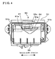
- Fig. 4 is a diagram viewed from an arrow IV shown in Fig. 2 ;
- Fig. 5 is an exploded perspective partial view of a mounting process of an operating handle and a counter weight according to the embodiment
- Fig. 6 is a cross sectional view taken along line VI- VI shown in Fig. 2 ;
- Fig. 7 is a cross sectional view taken along line VII- VII shown in Fig. 6 ;
- Fig. 8 is a cross sectional view of a counterweight according to a second embodiment.
- Fig. 1 is a rear side view of a vehicle 1.
- a back door 20 of the vehicle 1 is mounted on a vehicle body 10.
- the back door 20 can be opened and closed by means of a first door hinge 21 and a second door hinge 22 provided at upper and lower portions of the vehicle body 10 of Fig. 1 .
- a door lock device 30 and a door handle 50 are mounted at the back door 20 at a left side of Fig. 1 opposing the first and second door hinges 21 and 22 in a width direction relative to the vehicle 1.
- the door lock device 30 engages with a striker, which is mounted on the vehicle body 10, so as to lock the back door 20, thereby keeping the back door 20 closed.
- An operation displacement is transmitted via an interlocking cable 60 to unlock the door lock device 30 when operating the door handle 50.
- the back door 20 is opened by pulling the door handle 50 in a rearward direction of the vehicle.
- the door handle 50 is covered with a garnish 23 which is secured to the back door 20.
- Fig. 2 is a cross sectional view taken along line II- II in Fig. 1 .
- Fig. 3 is viewed from an arrow III in Fig. 2 .
- Fig. 4 is viewed from an arrow IV in Fig. 2 .
- the door handle 50 includes a base portion 51.
- the base portion 51 includes a mounting surface 51a which is provided along an inner part of a back door panel 24 of the back door 20 (see Fig. 1 ).
- a seal member 53 is provided between the mounting surface 51a and the back door panel 24.
- the back door panel 24 and the mounting surface 51a are fixed to each other through the seal member 53 by means of a screw.
- the base portion 51 is formed with first and second support arm portions 51b, which extend substantially horizontally in a rearward direction of the vehicle.
- the first and second support arm portions 51b are penetrating through a window portion 24a, which is provided at the back door panel 24.
- the first and second support arm portions 51b are provided at a predetermined space in the width direction of the vehicle.
- a horizontally extending rotation shaft of the handle (hereinafter referred to as a handle rotation shaft 54) is mounted on the first and second support arm portions 51b so as to serve as a bridge between the first and second support arm portion 51b.
- An operating handle 55 is provided between the first and second support arm portions 51b and is rotatably held by the handle rotation shaft 54.
- the operating handle 55 includes an operating portion 55b and an actuator arm 55a.
- the operating portion 55b extends rearwardly to a lower side of the handle rotation shaft 54.
- the actuator arm 55a extends horizontally forward on an opposite side from the operating handle 55 relative to the handle rotation shaft 54.
- the base portion 51 is formed with a drive shaft portion 51c, which stands upwardly and parallel in a forward direction of the vehicle. Further, a rotation shaft lever 52 is integrally mounted on the drive shaft portion 51c so as to be coaxial therewith. The rotation shaft lever 52 extends in a forward direction of the vehicle. A rotation lever 70 is rotatably held by the rotation shaft lever 52 and is retained by a retainer ring 52a.
- the rotation lever 70 is provided with two connecting arms 71 and a drive arm 73.
- the connecting arms 71 and the drive arm 73 extend in a radial direction about the rotation shaft lever 52.
- the interlocking cable 60 is formed with a cable case 61 and a cable 62 which is guided by the cable case 61.
- a case end portion 61 a of the cable case 61 is secured to a cable case mounting portion 57 which is mounted on the base portion 51.
- a tip end portion of one of the connecting arms 71 is engaged with a round shaped tip portion 62a which is provided at the cable 62.
- the other one of the connecting arms 71 is used in a vehicle, having a different design and where the door handle 50 is located at a different position.
- a spring 75 is mounted between the rotation lever 70 and the base portion 51.
- the spring 75 biases the rotation lever 70 in a counterclockwise direction as viewed in Fig. 3 .
- the actuator arm 55a of the operating handle 55 is in pressured contact with a tip end portion of the drive arm 73 of the rotation lever 70, so as to hold the rotation lever 70 to a predetermined position as shown in Fig. 3 .
- a counter weight 81 which is a main structure of the present embodiment, will be explained with reference to Figs. 2 , 4 to 7 .
- the counter weight 81 is mounted on the operating handle 55 so as prevent the operating handle 55 from moving and the door lock device 30 from unlocking, resulting from the acceleration that occurs when an excessively large impact is applied to the vehicle 1.
- Fig. 5 is an exploded perspective partial view of a mounting process with the operating handle 55 and the counter weight 81
- the operating handle 55 is formed with a support protrusion 55c (a first engagement portion) at the middle position in the width direction of the vehicle.
- the support protrusion 55c extends in an opposite direction from the operating portion 55b relative to the handle rotation shaft 54. In other words, the support protrusion 55c extends substantially in the same direction as the actuator arm 55a.
- the support protrusion 55c has a T shape in cross section, which is perpendicular to the longitudinal direction. As shown in Fig. 5 and Fig.
- a pair of hook portions 55f (retaining portions) is formed on the handle 55 so as to further protrude in a longitudinal direction from a tip portion of the support protrusion 55c.
- the counter weight 81 includes two opposing grooves 81b (a second engagement portion). The T-shaped portion of the support projection 55c is inserted to the two grooves 81b to engage therewith so that the counterweight 81 is mounted on the operation handle 55.
- the elastic deformable hook portions 55f fall to an inside of the grooves 81b and are reformed to an original shape after insertion. Consequently, as shown in Fig. 7 , the hook portions 55f hook into the edge surface of the counter weight 81.
- the operating handle 55 is formed with a contact surface 55g ( Fig. 5 ), which locks one edge surface of each of the grooves 81b. Another edge surface of each of the grooves 81b is depressed by the hook portion 55f. Accordingly, the counter weight 81 is locked without a rattle noise in an inserting direction.
- a side surface 55d of the support protrusion 55c attached to an inner surface of the groove 81b is formed with a small embossed portion 55e (a projecting portion) that slightly projects. Because the embossed portion 55e contacts the inner surface of the groove 81b by a predetermined load, the counter weight 81 is locked without a rattle in a width direction of the support protrusion 55c.
- the counter weight 81 is formed with a stopper portion 81a that extends to the handle rotation shaft 54.
- a tip portion of the stopper portion 81a hooks with the handle rotation shaft 54 by bending around the handle rotation shaft 54.
- the stopper portion 81a is formed into a key-shape for preventing the engagement between the counterweight 81 and the support protrusion 55c.
- the counter weight 81 is not required to be subassembled parts and is assembled with the other parts at the final assembling process.
- the counter weight 81 is not released from the operating handle 55 because the support protrusion 55c of the operating handle 55 is inserted into the grooves 81b of the counter weight 81 and then the handle rotation shaft 54 is mounted.
- the handle rotation shaft 54 and the counter weight 81 are generally formed by a material made of steel. Even when an excess impact is applied to the vehicle 1, the counter weight 81 may not be released from the operating handle 55 due to a breakage.
- An inserting load that is decided depending on the size of the embossed portion 55e is set to be small within a range where a rattle noise caused by a vibration that occurs in an ordinary usage of the vehicle 1 is prevented between the operating handle 55 and the counter weight 81. Therefore, the counter weight 81 may easily be inserted without requiring specific tools.
- Fig. 8 shows a shape of a counter weight 181 according to a second embodiment.
- a predetermined clearance A is provided between a stopper portion 181a of the counter weight 181 and the handle rotation shaft 54.
- the stopper portion 181a contacts the handle rotation shaft 54 so that the counter weight 181 is prevented from disengaging.
- the stopper portion 181a and the handle rotation shaft 54 do not contact each other, accordingly, door handle is obtained having a smooth operation.
- the counter weights 81 and 181 are flat shaped and formed in a compact shape.
- the counterweights 81 and 181 may be provided at an outside of the back door 20. Therefore, the other members in the back door 20 and the counter weights 81 and 181 are prevented from interfering with each other thus improving a design freedom.
- a leakage may occur at an inside of the back door 20 against the contact force of the seal member 53 while washing a car with a pressure washer and the like.
- a flange portion 51d is formed at the base portion 53 that is provided at the inside of the back door 20.
- mechanical parts such as the rotation lever 70 are provided close to the seal member 53.
- a door handle (50) for a vehicle (1) includes a base portion (51) adapted to be mounted on the vehicle door (20), a handle rotation shaft (54) supported by the base portion (51), an operating handle (55) rotatably held around the handle rotation shaft (54) and having a first engagement portion, and a counter weight (81,181) having a second engagement portion (81b) engaging with the first engagement portion provided at the operating handle (55) and a stopper portion (81a, 181a) preventing a disengagement between the first engagement portion (55c) of the operating handle (55) and the second engagement portion (81b) by connecting with the handle rotation shaft (54).
Landscapes
- Lock And Its Accessories (AREA)
Abstract
A door handle (50) for a vehicle (1) includes a base portion (51) adapted to be mounted on the vehicle door (20), a handle rotation shaft (54) supported by the base portion (51), an operating handle (55) rotatably held around the handle rotation shaft (54) and having a first engagement portion, and a counter weight (81,181) having a second engagement portion (81b) engaging with the first engagement portion provided at the operating handle (55) and a stopper portion (81a, 181a) preventing a disengagement between the first engagement portion (55c) of the operating handle (55) and the second engagement portion (81 b) by connecting with the handle rotation shaft (54).
Description
- The present invention relates to a door handle operating when opening a door.
- A door handle for a vehicle is operated to unlock a lock device to thereby open a door for a vehicle. Such door handle is applied to many different designs of vehicles or to doors provided at different portions of the vehicle such as a rear portion and a side portion. Thus, the component members are required to standardize whenever possible so as to reduce the manufacturing cost.
- A counter weight is mounted on the door handle for preventing a generation of a force to open the door at an operating handle portion when an excessive impact is applied to the vehicle. A weight of the counter weight differs depending on the characteristic of the vehicle and the mounting position of the door handle of the vehicle. Consequently, when a specific equipment such as a riveting device is necessary for assembling the operating handle portions and the counter weights, a great number of combinations of the operation handle portions and the counter weights are generated during the manufacturing process, which leads to a complicated manufacturing control.
- In order to reduce the manufacturing control complexity, a structure has been proposed where the counter weight and the operating handle portion are assembled, together with other parts of the door handle, at the final assembling process. Such door handle is disclosed in
JP3472181B - However, according to the door handle disclosed in
JP3472181B - A need thus exists for a door handle for a vehicle having a structure in which a mounting process for preventing a disengagement between a counter weight and an operation handle portion is not required.
- According to an aspect of the present invention, a door handle for a vehicle includes a base portion adapted to be mounted on the vehicle door, a handle rotation shaft supported by the base portion, an operating handle rotatably held around the handle rotation shaft and having a first engagement portion, and a counter weight having a second engagement portion engaging with the first engagement portion provided at the operating handle and a stopper portion preventing a disengagement between the first engagement portion of the operating handle and the second engagement portion by connecting with the handle rotation shaft.
- According to the aforementioned invention, the engagement between the counter weight and the operating handle is prevented from releasing because the handle rotation shaft is mounted on the door handle. Thus, in the process of mounting the counter weight, a complicated operating procedure that requires a certain skill is not necessary for preventing the engagement between the counter weight and the operating handle from releasing. Therefore, the manufacturing process of the door handle becomes simple, which leads to an improved productivity.
- A projecting portion is formed on either the first engagement portion or the second engagement portion, in a state where the first engagement portion and the second engagement portion are mutually in contact with each other.
- Accordingly, the rattle noise caused by a vibration at the engagement portion between the first engagement portion and the second engagement portion is prevented.
- A retaining portion is formed on either the counter weight or the operating handle for preventing a release of the engagement between the first engagement portion and the second engagement portion and wherein a predetermined space is provided between the stopper portion and the handle rotation shaft.
- Because the predetermined space is provided between the stopper portion and the handle rotation shaft, a friction is prevented from being generated between the stopper portion and the handle rotation shaft. As a result, the excellent operation performance of the door handle may be achieved. In an emergency such as when an excessively large impact is applied to the vehicle, the stopper portion and the handle rotation shaft make contact with each other so that the engagement between the first engagement portion and the second engagement portion is ensured.
- The foregoing and additional features and characteristics of the disclosure will become more apparent from the following detailed description considered with the reference to the accompanying drawings, wherein:
-
Fig. 1 is a rear side view of a vehicle including a door handle according to a first embodiment; -
Fig. 2 is a cross sectional view taken along line II- II shown inFig. 1 ; -
Fig. 3 is a diagram viewed from an arrow III shown inFig. 2 ; -
Fig. 4 is a diagram viewed from an arrow IV shown inFig. 2 ; -
Fig. 5 is an exploded perspective partial view of a mounting process of an operating handle and a counter weight according to the embodiment; -
Fig. 6 is a cross sectional view taken along line VI- VI shown inFig. 2 ; -
Fig. 7 is a cross sectional view taken along line VII- VII shown inFig. 6 ; -
Fig. 8 is a cross sectional view of a counterweight according to a second embodiment. - An embodiment will be explained with reference to the attached drawings.
-
Fig. 1 is a rear side view of avehicle 1. Aback door 20 of thevehicle 1 is mounted on avehicle body 10. Theback door 20 can be opened and closed by means of afirst door hinge 21 and asecond door hinge 22 provided at upper and lower portions of thevehicle body 10 ofFig. 1 . - A
door lock device 30 and adoor handle 50 are mounted at theback door 20 at a left side ofFig. 1 opposing the first and second door hinges 21 and 22 in a width direction relative to thevehicle 1. - The
door lock device 30 engages with a striker, which is mounted on thevehicle body 10, so as to lock theback door 20, thereby keeping theback door 20 closed. - An operation displacement is transmitted via an
interlocking cable 60 to unlock thedoor lock device 30 when operating thedoor handle 50. Further, theback door 20 is opened by pulling thedoor handle 50 in a rearward direction of the vehicle. In addition, thedoor handle 50 is covered with agarnish 23 which is secured to theback door 20. -
Fig. 2 is a cross sectional view taken along line II- II inFig. 1 .Fig. 3 is viewed from an arrow III inFig. 2 . Further,Fig. 4 is viewed from an arrow IV inFig. 2 . - As shown in
Fig. 2 ,Fig. 3 , andFig. 4 , thedoor handle 50 includes abase portion 51. Thebase portion 51 includes amounting surface 51a which is provided along an inner part of aback door panel 24 of the back door 20 (seeFig. 1 ). Aseal member 53 is provided between themounting surface 51a and theback door panel 24. Theback door panel 24 and themounting surface 51a are fixed to each other through theseal member 53 by means of a screw. Thebase portion 51 is formed with first and secondsupport arm portions 51b, which extend substantially horizontally in a rearward direction of the vehicle. The first and secondsupport arm portions 51b are penetrating through awindow portion 24a, which is provided at theback door panel 24. - The first and second
support arm portions 51b are provided at a predetermined space in the width direction of the vehicle. A horizontally extending rotation shaft of the handle (hereinafter referred to as a handle rotation shaft 54) is mounted on the first and secondsupport arm portions 51b so as to serve as a bridge between the first and secondsupport arm portion 51b. Anoperating handle 55 is provided between the first and secondsupport arm portions 51b and is rotatably held by thehandle rotation shaft 54. Theoperating handle 55 includes anoperating portion 55b and anactuator arm 55a. Theoperating portion 55b extends rearwardly to a lower side of thehandle rotation shaft 54. Theactuator arm 55a extends horizontally forward on an opposite side from theoperating handle 55 relative to thehandle rotation shaft 54. - The
base portion 51 is formed with adrive shaft portion 51c, which stands upwardly and parallel in a forward direction of the vehicle. Further, arotation shaft lever 52 is integrally mounted on thedrive shaft portion 51c so as to be coaxial therewith. Therotation shaft lever 52 extends in a forward direction of the vehicle. Arotation lever 70 is rotatably held by therotation shaft lever 52 and is retained by aretainer ring 52a. - As shown in
Fig. 3 , therotation lever 70 is provided with two connectingarms 71 and adrive arm 73. The connectingarms 71 and thedrive arm 73 extend in a radial direction about therotation shaft lever 52. The interlockingcable 60 is formed with acable case 61 and acable 62 which is guided by thecable case 61. Acase end portion 61 a of thecable case 61 is secured to a cablecase mounting portion 57 which is mounted on thebase portion 51. A tip end portion of one of the connectingarms 71 is engaged with a round shapedtip portion 62a which is provided at thecable 62. The other one of the connectingarms 71 is used in a vehicle, having a different design and where thedoor handle 50 is located at a different position. - As shown in
Fig. 2 andFig. 3 , aspring 75 is mounted between therotation lever 70 and thebase portion 51. Thespring 75 biases therotation lever 70 in a counterclockwise direction as viewed inFig. 3 . Theactuator arm 55a of theoperating handle 55 is in pressured contact with a tip end portion of thedrive arm 73 of therotation lever 70, so as to hold therotation lever 70 to a predetermined position as shown inFig. 3 . - In the structure explained above, when pulling the operating
portion 55b of thedoor handle 50 in a rearward direction of the vehicle, theactuator arm 55a moves downwardly inFig. 3 and therotation lever 70 rotates in a clockwise direction against the biasing force of thespring 75. - Because the
rotation lever 70 rotates in the clockwise direction, thetip portion 62a of thecable 62 is pulled away from thecase end portion 61a. Then, the other end portion of thecable 62, which is connected to thedoor lock device 30 is pulled to thereby unlock thedoor lock device 30. - Next, a
counter weight 81, which is a main structure of the present embodiment, will be explained with reference toFigs. 2 ,4 to7 . Thecounter weight 81 is mounted on the operating handle 55 so as prevent the operating handle 55 from moving and thedoor lock device 30 from unlocking, resulting from the acceleration that occurs when an excessively large impact is applied to thevehicle 1. -
Fig. 5 is an exploded perspective partial view of a mounting process with the operatinghandle 55 and thecounter weight 81, The operatinghandle 55 is formed with asupport protrusion 55c (a first engagement portion) at the middle position in the width direction of the vehicle. Thesupport protrusion 55c extends in an opposite direction from the operatingportion 55b relative to thehandle rotation shaft 54. In other words, thesupport protrusion 55c extends substantially in the same direction as theactuator arm 55a. As shown inFig. 6 , thesupport protrusion 55c has a T shape in cross section, which is perpendicular to the longitudinal direction. As shown inFig. 5 andFig. 7 , a pair ofhook portions 55f (retaining portions) is formed on thehandle 55 so as to further protrude in a longitudinal direction from a tip portion of thesupport protrusion 55c. Thecounter weight 81 includes two opposinggrooves 81b (a second engagement portion). The T-shaped portion of thesupport projection 55c is inserted to the twogrooves 81b to engage therewith so that thecounterweight 81 is mounted on theoperation handle 55. - When the
support protrusion 55c is inserted into thegrooves 81b, the elasticdeformable hook portions 55f fall to an inside of thegrooves 81b and are reformed to an original shape after insertion. Consequently, as shown inFig. 7 , thehook portions 55f hook into the edge surface of thecounter weight 81. The operatinghandle 55 is formed with acontact surface 55g (Fig. 5 ), which locks one edge surface of each of thegrooves 81b. Another edge surface of each of thegrooves 81b is depressed by thehook portion 55f. Accordingly, thecounter weight 81 is locked without a rattle noise in an inserting direction. - In addition, a
side surface 55d of thesupport protrusion 55c attached to an inner surface of thegroove 81b is formed with a small embossedportion 55e (a projecting portion) that slightly projects. Because the embossedportion 55e contacts the inner surface of thegroove 81b by a predetermined load, thecounter weight 81 is locked without a rattle in a width direction of thesupport protrusion 55c. - As shown in
Fig. 2 andFig. 5 , thecounter weight 81 is formed with astopper portion 81a that extends to thehandle rotation shaft 54. A tip portion of thestopper portion 81a hooks with thehandle rotation shaft 54 by bending around thehandle rotation shaft 54. Thestopper portion 81a is formed into a key-shape for preventing the engagement between thecounterweight 81 and thesupport protrusion 55c. - In a structure of the
door handle 50 explained above, it is not required to premount to the operating handle 55 to thecounter weight 81. Thecounter weight 81 is not required to be subassembled parts and is assembled with the other parts at the final assembling process. - As shown in
Fig. 5 , thecounter weight 81 is not released from the operatinghandle 55 because thesupport protrusion 55c of theoperating handle 55 is inserted into thegrooves 81b of thecounter weight 81 and then thehandle rotation shaft 54 is mounted. Thehandle rotation shaft 54 and thecounter weight 81 are generally formed by a material made of steel. Even when an excess impact is applied to thevehicle 1, thecounter weight 81 may not be released from the operatinghandle 55 due to a breakage. - An inserting load that is decided depending on the size of the embossed
portion 55e is set to be small within a range where a rattle noise caused by a vibration that occurs in an ordinary usage of thevehicle 1 is prevented between the operatinghandle 55 and thecounter weight 81. Therefore, thecounter weight 81 may easily be inserted without requiring specific tools. -
Fig. 8 shows a shape of acounter weight 181 according to a second embodiment. A predetermined clearance A is provided between astopper portion 181a of thecounter weight 181 and thehandle rotation shaft 54. When an excessive impact is applied to thevehicle 1, thestopper portion 181a contacts thehandle rotation shaft 54 so that thecounter weight 181 is prevented from disengaging. Under normal operation, thestopper portion 181a and thehandle rotation shaft 54 do not contact each other, accordingly, door handle is obtained having a smooth operation. - According to the structure explained above, the
counter weights counterweights back door 20. Therefore, the other members in theback door 20 and thecounter weights - Even when the
door handle 50 is covered with thegarnish 23, a leakage may occur at an inside of theback door 20 against the contact force of theseal member 53 while washing a car with a pressure washer and the like. As shown inFig. 2 , aflange portion 51d is formed at thebase portion 53 that is provided at the inside of theback door 20. Meanwhile, in thedoor handle 50 that is designed compactly because thecounter weight 81 is arranged at the outside of theback door 20, mechanical parts such as therotation lever 70 are provided close to theseal member 53. When a leakage occurs at the inside of theback door 20 against the contact force of theseal member 53, theU-shaped flange portion 51d that opens rearwards guides the leaked water and prevents the water from attaching to the mechanical parts. Consequently, functions of thedoor handle 50 may not be damaged due to a freezing of the mechanical parts, for example. - According to the aforementioned embodiment, the
door handle 50 is applied to theback door 20. Alternatively, thedoor handle 50 is applicable to a side door, A door handle (50) for a vehicle (1) includes a base portion (51) adapted to be mounted on the vehicle door (20), a handle rotation shaft (54) supported by the base portion (51), an operating handle (55) rotatably held around the handle rotation shaft (54) and having a first engagement portion, and a counter weight (81,181) having a second engagement portion (81b) engaging with the first engagement portion provided at the operating handle (55) and a stopper portion (81a, 181a) preventing a disengagement between the first engagement portion (55c) of the operating handle (55) and the second engagement portion (81b) by connecting with the handle rotation shaft (54).
Claims (3)
- A door handle (50) for a vehicle door (20), comprising:a base portion (51) adapted to be mounted on the vehicle door (20);a handle rotation shaft (54) supported by the base portion (51);an operating handle (55) rotatably held around the handle rotation shaft (54) and having a first engagement portion (55c); anda counterweight (81, 181) having a second engagement portion (81 b) engaging with the first engagement portion (55c) provided at the operating handle (55) and a stopper portion (81 a, 181a) preventing a disengagement between the first engagement portion (55c) of the operating handle (55) and the second engagement portion (81 b) by connecting with the handle rotation shaft (54).
- The door handle according to claim 1, wherein a projecting portion (55e) is formed on either the first engagement portion (55c) or the second engagement portion (81 b), in a state where the first engagement portion (55c) and the second engagement portion (81 b) are mutually in contact with each other.
- The door handle according to claim 1 or claim 2, wherein a retaining portion (55f) is formed on either the counter weight (81, 181) or the operating handle (55) for preventing a release of the engagement between the first engagement portion (55c) and the second engagement portion (81 b) and wherein a predetermined space is provided between the stopper portion (81a, 181a) and the handle rotation shaft (54).
Applications Claiming Priority (1)
| Application Number | Priority Date | Filing Date | Title |
|---|---|---|---|
| JP2008248500A JP5146228B2 (en) | 2008-09-26 | 2008-09-26 | Vehicle door handle |
Publications (1)
| Publication Number | Publication Date |
|---|---|
| EP2169149A2 true EP2169149A2 (en) | 2010-03-31 |
Family
ID=41591675
Family Applications (1)
| Application Number | Title | Priority Date | Filing Date |
|---|---|---|---|
| EP20090171094 Withdrawn EP2169149A2 (en) | 2008-09-26 | 2009-09-23 | Door handle for vehicle |
Country Status (4)
| Country | Link |
|---|---|
| US (1) | US20100078947A1 (en) |
| EP (1) | EP2169149A2 (en) |
| JP (1) | JP5146228B2 (en) |
| CN (1) | CN101684694A (en) |
Cited By (3)
| Publication number | Priority date | Publication date | Assignee | Title |
|---|---|---|---|---|
| WO2012101121A1 (en) * | 2011-01-26 | 2012-08-02 | Huf Hülsbeck & Fürst Gmbh & Co. Kg | Handle for a motor vehicle |
| WO2013027226A3 (en) * | 2011-06-10 | 2013-04-25 | Illinois Tool Works Inc. | Door handle assembly |
| FR3092356A1 (en) * | 2019-02-05 | 2020-08-07 | Mgi Coutier Espana | Motor vehicle handle system with inertial safety device. |
Families Citing this family (9)
| Publication number | Priority date | Publication date | Assignee | Title |
|---|---|---|---|---|
| KR101163461B1 (en) * | 2010-11-03 | 2012-07-18 | 삼보에이앤티 주식회사 | Device for assembling outside handle of vehicle |
| CN102418432B (en) * | 2011-10-26 | 2014-02-05 | 奇瑞汽车股份有限公司 | Automobile door outer handle |
| WO2013099758A1 (en) * | 2011-12-28 | 2013-07-04 | 本田技研工業株式会社 | Vehicle door |
| JP5958939B2 (en) * | 2013-07-25 | 2016-08-02 | 株式会社ホンダロック | Vehicle door handle device |
| JP6732384B2 (en) * | 2016-10-27 | 2020-07-29 | ダイハツ工業株式会社 | Door structure |
| DE102017130573A1 (en) * | 2017-12-19 | 2019-06-19 | Huf Hülsbeck & Fürst GmbH & Co KG | Door handle assembly of a motor vehicle |
| FR3081489B1 (en) * | 2018-05-25 | 2022-09-09 | U Shin Italia Spa | OPENING HANDLE DEVICE, IN PARTICULAR FOR VEHICLES |
| CN114396203A (en) * | 2021-12-31 | 2022-04-26 | 东风汽车集团股份有限公司 | Hidden handle foundation structure of car, hidden handle and car |
| CN116556791A (en) * | 2023-05-25 | 2023-08-08 | 重庆长安汽车股份有限公司 | A handle structure and assembly method for a back door opening outward |
Citations (1)
| Publication number | Priority date | Publication date | Assignee | Title |
|---|---|---|---|---|
| JP3472181B2 (en) | 1999-03-11 | 2003-12-02 | 株式会社アルファ | Door handle device for vehicles with counter weight |
Family Cites Families (18)
| Publication number | Priority date | Publication date | Assignee | Title |
|---|---|---|---|---|
| JPS5527948B2 (en) * | 1972-02-21 | 1980-07-24 | ||
| DE19624640C1 (en) * | 1996-06-20 | 1998-01-08 | Kiekert Ag | Vehicle doorlock with pivoting latch |
| JP4122081B2 (en) * | 1997-12-18 | 2008-07-23 | 株式会社ホンダロック | Assembly structure of vehicle door handle device |
| US6575508B2 (en) * | 2000-04-21 | 2003-06-10 | Adac Plastics, Inc. | Handle with unidirectional counterweight |
| US6554331B2 (en) * | 2000-12-11 | 2003-04-29 | Daimlerchrysler Corporation | Outside door handle for a motor vehicle |
| JP3794291B2 (en) * | 2001-06-29 | 2006-07-05 | スズキ株式会社 | Door handle assembly structure |
| KR100412833B1 (en) * | 2001-07-12 | 2003-12-31 | 현대자동차주식회사 | A non housing grip type door handle and assembling process of the same |
| JP4136835B2 (en) * | 2003-07-18 | 2008-08-20 | 株式会社アルファ | Outside handle device for automobile |
| US7029042B2 (en) * | 2004-01-22 | 2006-04-18 | Illinois Tool Works Inc | Automobile door handle |
| JP4015635B2 (en) * | 2004-03-17 | 2007-11-28 | アイシン精機株式会社 | Vehicle door handle device |
| EP1582659B1 (en) * | 2004-03-29 | 2013-03-20 | Aisin Seiki Kabushiki Kaisha | Door handle for vehicle |
| ITRM20040337A1 (en) * | 2004-07-07 | 2004-10-07 | Valeo Sicurezza Abitacolo Spa | DOOR HANDLE, IN PARTICULAR OF THE VEHICLE, WITH INERTIAL SAFETY SYSTEM. |
| US7284776B2 (en) * | 2004-08-04 | 2007-10-23 | Adac Plastics, Inc. | Vehicular door handle included secondary latch |
| US7070216B2 (en) * | 2004-09-09 | 2006-07-04 | Siegel-Robert, Inc. | Vehicle door handle assembly |
| CN2765986Y (en) * | 2005-01-13 | 2006-03-22 | 奇瑞汽车有限公司 | Automobile door handle |
| KR100737001B1 (en) * | 2005-10-07 | 2007-07-09 | 현대자동차주식회사 | Safety mechanism of vehicle door handle assembly |
| US7481468B2 (en) * | 2006-10-25 | 2009-01-27 | Ford Global Technologies, Llc | Apparatus for blocking the movement of an inertially activated component |
| KR100792931B1 (en) * | 2006-12-12 | 2008-01-08 | 기아자동차주식회사 | Door opening prevention device in case of side collision of door out side handle |
-
2008
- 2008-09-26 JP JP2008248500A patent/JP5146228B2/en not_active Expired - Fee Related
-
2009
- 2009-09-23 EP EP20090171094 patent/EP2169149A2/en not_active Withdrawn
- 2009-09-24 CN CN200910175608A patent/CN101684694A/en active Pending
- 2009-09-24 US US12/566,052 patent/US20100078947A1/en not_active Abandoned
Patent Citations (1)
| Publication number | Priority date | Publication date | Assignee | Title |
|---|---|---|---|---|
| JP3472181B2 (en) | 1999-03-11 | 2003-12-02 | 株式会社アルファ | Door handle device for vehicles with counter weight |
Cited By (5)
| Publication number | Priority date | Publication date | Assignee | Title |
|---|---|---|---|---|
| WO2012101121A1 (en) * | 2011-01-26 | 2012-08-02 | Huf Hülsbeck & Fürst Gmbh & Co. Kg | Handle for a motor vehicle |
| CN103339333A (en) * | 2011-01-26 | 2013-10-02 | 霍弗·霍斯贝克及弗斯特两合公司 | Handle for a motor vehicle |
| CN103339333B (en) * | 2011-01-26 | 2016-10-05 | 霍弗·霍斯贝克及弗斯特两合公司 | Motor vehicle handle |
| WO2013027226A3 (en) * | 2011-06-10 | 2013-04-25 | Illinois Tool Works Inc. | Door handle assembly |
| FR3092356A1 (en) * | 2019-02-05 | 2020-08-07 | Mgi Coutier Espana | Motor vehicle handle system with inertial safety device. |
Also Published As
| Publication number | Publication date |
|---|---|
| CN101684694A (en) | 2010-03-31 |
| JP5146228B2 (en) | 2013-02-20 |
| US20100078947A1 (en) | 2010-04-01 |
| JP2010077718A (en) | 2010-04-08 |
Similar Documents
| Publication | Publication Date | Title |
|---|---|---|
| US20100078947A1 (en) | Door handle for vehicle | |
| JP6155488B2 (en) | Locking device having a claw portion having a plurality of parts | |
| US12065862B2 (en) | Motor vehicle lock | |
| US8764077B2 (en) | Vehicle door lock device | |
| CN104145071B (en) | The locking system of open-close body | |
| US8840156B2 (en) | Handle for a door leaf of an automobile | |
| US8677690B2 (en) | Fuel door opening/closing apparatus for vehicle | |
| US9410345B2 (en) | Vehicle door lock device | |
| KR20120096938A (en) | Actuator for vehicle door latch device | |
| CN101899931A (en) | The cable-actuated inertial lock that is used for car door | |
| EP3181952B1 (en) | Operating apparatus for emergency release cable | |
| JP5338369B2 (en) | Vehicle door lock device | |
| JP4233975B2 (en) | Vehicle door lock device | |
| JP4345432B2 (en) | Vehicle door latch mechanism | |
| KR20060062052A (en) | Unlatch structure of the door outside handle | |
| JP6078881B2 (en) | Door latch device for automobile | |
| CN108316791B (en) | Automobile glove box | |
| JP4168732B2 (en) | Tailgate door opening prevention mechanism | |
| JP2017214013A (en) | Door structure of vehicle | |
| JP2009166640A (en) | Glove box lock unit mounting structure | |
| JP6089299B2 (en) | Door latch device for automobile | |
| JP2014214536A (en) | Vehicle door latch device | |
| JP6197199B2 (en) | Door latch device for automobile | |
| JP3736805B2 (en) | Biaxial hinge door latch device | |
| JP2018096046A (en) | Vehicle door lock device |
Legal Events
| Date | Code | Title | Description |
|---|---|---|---|
| PUAI | Public reference made under article 153(3) epc to a published international application that has entered the european phase |
Free format text: ORIGINAL CODE: 0009012 |
|
| AK | Designated contracting states |
Kind code of ref document: A2 Designated state(s): AT BE BG CH CY CZ DE DK EE ES FI FR GB GR HR HU IE IS IT LI LT LU LV MC MK MT NL NO PL PT RO SE SI SK SM TR |
|
| AX | Request for extension of the european patent |
Extension state: AL BA RS |
|
| STAA | Information on the status of an ep patent application or granted ep patent |
Free format text: STATUS: THE APPLICATION HAS BEEN WITHDRAWN |
|
| 18W | Application withdrawn |
Effective date: 20111025 |