EP2169107A1 - Drying appliance comprising a spraying device - Google Patents
Drying appliance comprising a spraying device Download PDFInfo
- Publication number
- EP2169107A1 EP2169107A1 EP09171401A EP09171401A EP2169107A1 EP 2169107 A1 EP2169107 A1 EP 2169107A1 EP 09171401 A EP09171401 A EP 09171401A EP 09171401 A EP09171401 A EP 09171401A EP 2169107 A1 EP2169107 A1 EP 2169107A1
- Authority
- EP
- European Patent Office
- Prior art keywords
- spraying
- air
- drying appliance
- channel
- appliance according
- Prior art date
- Legal status (The legal status is an assumption and is not a legal conclusion. Google has not performed a legal analysis and makes no representation as to the accuracy of the status listed.)
- Granted
Links
- 238000005507 spraying Methods 0.000 claims abstract description 104
- XLYOFNOQVPJJNP-UHFFFAOYSA-N water Substances O XLYOFNOQVPJJNP-UHFFFAOYSA-N 0.000 claims abstract description 45
- 238000001035 drying Methods 0.000 claims abstract description 38
- 238000001816 cooling Methods 0.000 claims description 9
- 230000005484 gravity Effects 0.000 claims description 4
- 238000011010 flushing procedure Methods 0.000 abstract description 11
- 238000005381 potential energy Methods 0.000 abstract description 3
- 239000002699 waste material Substances 0.000 abstract description 2
- 238000010438 heat treatment Methods 0.000 description 7
- 239000004744 fabric Substances 0.000 description 6
- 239000002826 coolant Substances 0.000 description 3
- 230000000694 effects Effects 0.000 description 3
- 239000007921 spray Substances 0.000 description 3
- 238000009833 condensation Methods 0.000 description 1
- 230000005494 condensation Effects 0.000 description 1
- 239000000835 fiber Substances 0.000 description 1
- 239000012634 fragment Substances 0.000 description 1
- 230000008676 import Effects 0.000 description 1
- 238000000034 method Methods 0.000 description 1
- 238000012986 modification Methods 0.000 description 1
- 230000004048 modification Effects 0.000 description 1
- 239000000126 substance Substances 0.000 description 1
- 239000004753 textile Substances 0.000 description 1
- 238000005406 washing Methods 0.000 description 1
Images

Classifications
-
- D—TEXTILES; PAPER
- D06—TREATMENT OF TEXTILES OR THE LIKE; LAUNDERING; FLEXIBLE MATERIALS NOT OTHERWISE PROVIDED FOR
- D06F—LAUNDERING, DRYING, IRONING, PRESSING OR FOLDING TEXTILE ARTICLES
- D06F58/00—Domestic laundry dryers
- D06F58/20—General details of domestic laundry dryers
- D06F58/24—Condensing arrangements
Definitions
- the present invention relates to an improved drying appliance, such as a dryer or a washer-dryer, and in particular to a fabric drying appliance which comprises a drum, a condensing device, a drying channel for introducing processing air into the drum, and a spraying device associated with the condensing device such that it is operable to flush off fluff adhered on the condensing device.
- a fabric drying appliance which comprises a drum, a condensing device, a drying channel for introducing processing air into the drum, and a spraying device associated with the condensing device such that it is operable to flush off fluff adhered on the condensing device.
- a drying appliance such as dryer or washer-dryer for use as a household appliance, has the following drying process: After being heated by a heating device, dry processing air is heated within a heating channel, and is driven into a drum wherein heat is exchanged between the heated processing air and the wet fabric to evaporate moisture from the fabric into the processing air, such that the processing air carries moisture from the fabric and moves into the condensing device through an exit which is formed on the drum. Condensed by the condensing device, the moisture of the processing air is turned to water, and the processing air becomes relatively dry and cool. The condensed processing air is then driven by a fan to a heating channel and heated again to enter the drum in a next drying cycle.
- fluff which is dust-like fragments of textile fibers is always produced and carried by the moist processing air into the condensing assembly, and then is adhered on inner walls of the condensing device, which influences effect of condensing or blocks up the processing air. And also, fluff may even be driven into the fan and the heating device, which may cause dangers.
- a spraying device to clean the condensing device and possibly other parts of the drying device by water spray may be provided.
- Some drawbacks are commonly existent in the spraying devices of prior art, which are: the effective area that is cleaned by the water spray is extremely limited; water pressure is dispersed, and force of flushing is not big enough, and so on.
- EP 0 636 732 A1 disclosed a presently known spraying device uses spraying water, which is splashed from a certain baffle, to wash off fluff from the condensing device. With such structure, potential energy of the water is somewhat consumed when it hits the baffle, so the force of flushing is weakened. And under most conditions, a spraying device only has one spraying hole, or otherwise has several spread distributed spraying holes, and thus the flushing area is extremely limited, or the water pressure is dispersed, which also decrease effect of condensing.
- condensing devices there are several sorts of condensing devices, one of which uses water and others use other coolant, such as air, for condensation.
- a condensing device of other coolant is preferred for saving water, but meanwhile has much more problems with the fluff, which will be described in detail hereinafter.
- the spraying water of a water-condensing device will carry a portion of fluff in the processing air, and also will flush at least a portion of the inner walls of the condensing device.
- An air-condensing device usually imports fresh air from outside of the drying appliance. The fresh air will then cool down the processing air within the condensing device, and subsequently flows out of the drying appliance.
- the condensing device usually has several processing air channels, which usually have elongate section such as to make the processing air be well cooled. So it is quite difficult to completely wash each processing air channel.
- DE 37 38 031 C1 discloses such a known spraying device for the air-condensing device: the spraying device has a water inlet tube and a series of spraying heads distributed along a line towards the flowing direction of the water. And each of the spraying head associates with a processing air channel. Each spraying head has only one spraying direction, such that the effective area is relatively small.
- the disadvantages of the system as set forth above are: Firstly, the spraying heads are aligned in a line, such that the water pressure is dispersed and unsymmetrical, and the flush force of the spraying water is relatively small and unsymmetrical.
- the spraying heads only wash the processing air channels, such that the processing air inlet channel and outlet channel which are connected to the condensing device can not be washed; and also, each spraying head only has one spraying hole, and the effective area is relatively small, such that the processing air channels can not be fully washed.
- An object of the present invention is to provide an improved drying appliance, which overcomes the foregoing drawbacks of the prior art, and has more reliable effect of flushing off fluff.
- a drying appliance such as a dryer or a washer-dryer
- a drying appliance which comprises a drum, a drying channel for introducing processing air into the drum, a condensing device, a spraying device associated with the condensing device, said spraying device having a water inlet and an end portion, wherein the spraying device further has a spraying head which is provided on the end portion thereof; and wherein said spraying head is in the form of a cup, and has plurality of spraying holes.
- the spraying head is provided on the end portion of the spraying device, the water pressure is thereby concentrated, and because of the cup-shaped form of the spraying head, waste of potential energy is minimized, such that the flushing force is relatively large, and the spraying area is relatively large, which is good for flushing off fluff and good for condensing as well.
- the spraying holes oriented in different directions. So the effective flushing area is relatively large.
- the spraying head has an axis, around which the spraying holes are distributed. Therefore, the water pressure is relatively symmetrical, and also enlarges the effective flushing area.
- a respective wedge-shaped splitter disposed between each two spraying holes. Therefore, water is smoothly guided into the spraying holes.
- the wedge-shaped splitters connected with each other at bottom ends thereof, and have knife-edges joining at a central point such as to form wedge-shaped slots radially distributed and beginning from the point, wherein the wedge-shaped slots form a portion of the spraying holes. Therefore, the water comes from the water inlet tube will not be blocked by any surface; instead, it will be well guided to the slots smoothly.
- the spraying head has a round wall on which the spraying holes are formed. Since the spraying holes are formed on a round wall, they are three-dimensionally disposed, and the water ejected from the spraying holes has relatively big work area.
- said condensing device has at least one processing air channel and at least one cooling air channel arranged in heat-exchanging relation to each other, such that water is saved for condensing, and good spraying device is especially need for such kind of condensing device.
- the at least one processing air channel comprising two ends respectively connected to an air-inlet channel and an air-outlet channel
- said spraying device is mounted on one of the air-inlet channel and the air-outlet channel. Therefore, the air-inlet channel and the air-outlet channel can also be washed from fluff.
- said at least one processing air channel is substantially vertically disposed, and the spraying device is disposed there above in relation to a direction of gravity. Therefore, water drops from the spraying device and onto the processing air channel. Because of the gravity, the water has more reliable flushing force.
- the spraying device is mounted on a topmost portion of the one of the air-inlet channel and the air-outlet channel. Therefore, the air-inlet channel or air-outlet channel on which the spraying device is mounted can be fully cleaned.
- said axis of the spraying head aligned with a central portion of said at least one processing air channel. Therefore, water from the spraying device is symmetrically spread.
- the spraying head is disposed below the water inlet tube, such that energy of the water flow is increased when it drops from the water inlet tube to the spraying head, and thus the water spray has relatively big flushing force.
- the spraying device has an interior that is connected to an outside of the drying appliance by an air-guiding connection, and includes a water line projecting through the interior and has an opening within the interior.
- the inventive drying appliance is embodied in a household appliance, in particular in a laundry dryer or a washer/dryer.
- the present invention is applicable for drying appliance having either an air-cooled or water-cooled condenser, or even having a condenser cooled by any coolant, while in the embodiments which will are described hereinbelow, an air-cooled condenser is used as an example.
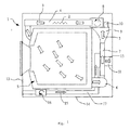
- a drying appliance 1 is under drying process.
- dry processing air 3 is heated by a heating device 2 within a heating channel 4, and is driven into a drum 5 whereat heat exchanged between the heated processing air 3 and wet fabric, such that the processing air 3 carries moisture from the fabric and moves into the condensing device 7 through a condensing air-inlet channel 6.
- Condensed by the condensing device 7, the moisture of the processing air 3 is turned to water, and the processing air 3 becomes relatively dry and cool.
- the condensed processing air 3 is then driven by a first fan 8 through a condensing air-outlet channel 9 to the heating channel 4 to enter a next dying cycle.
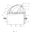
- the condensing device 7 is connected to the condensing air-inlet channel 6 and the condensing air-outlet channel 9 at its two ends, and has at least one processing air channel 11 and at least one cooling air channel 12 which are arranged in heat-exchanging relation to each other.
- the at least one processing air channel 11 is substantially perpendicular to a bottom surface 14 of a housing 13 of the drying appliance 1.
- a spraying device 10 is mounted on the condensing air-outlet channel 9, and is above the condensing device 7 in relation to a direction of gravity.
- the processing air channel 11 may be inclined or parallel to the bottom surface 14.
- the spraying device 10 may be mounted on the condensing air-inlet channel 6.
- Fresh cooling air 15 from outside of the housing 13 is driven by a second fan 16 into a cooling air inlet channel 17, and subsequently into the cooling air channel 12 whereat heat exchanged between the cooling air 15 and the processing air 3 which is in the processing air channel 11. Then the processing air 3 is cooled down, and the cooling air 15 is discharged out of the housing 13 through a cooling air outlet channel 18.
- the spraying device 10 comprises a water inlet tube 19 and an end portion 33.
- a spraying head 20 is disposed on the end portion 33.
- a guiding device 21 disposed between the water inlet tube 19 and the spraying head 20 for guiding the water from the water inlet tube 19 to the spraying head 20.
- the guiding device 21 may connected with the water inlet tube 19 such as to form a portion of the water inlet tube 19.
- the spraying head 20 is in the form of a cup, at the end of which a semi-spherical wall 22 is formed. Pluralities of spraying holes 23 with different directions are formed on the semi-spherical wall 22.
- the spraying holes 23 are radially distributed around a central axis 24 of the spraying head 20.
- the spraying head 20 may have other cup shape.
- cup shape can be defined as a tridimensional component which has a continuously connected bottom and side wall, and an opening opens at one end.
- the cup shape may also have other appropriate definition.
- the spraying head 20 may also be tapered, columned, or has other shape of curved wall or prismatic walls.
- the spraying holes 23 may have other form of distributing, for instance, distributed axially and radially at the same time with multiple layers.
- the spraying device 10 has an interior 30 that is connected to outside of the drying appliance 1 by an air-guiding connection 31, and includes a water line defined by the water inlet tube 19 and the guiding device 21 projecting through the interior 30 and has an opening 32 within the interior 30.
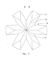
- wedge-shaped splitters 25 are formed between each two spraying holes 23.
- the wedge-shaped splitters 25 connected with each other at bottom ends thereof, and have knife-edges 26 join at a central point 27 such as to form wedge-shaped slots 28 radially distributed and beginning from the point 27.
- the wedge-shaped slots 28 form a portion of the spraying holes 23.
- the point 27 is on the central axis 24 of the spraying head 20. Because of the structure, the water is divided by the knife-edges 26 when it flows to the bottom of the spraying head 20, and is guided to the spraying holes 23 smoothly.
- the axis 24 of the spraying head 20 aligned with a central portion 29 of the at least one processing air channel 11.
- the spraying device 10 is preferably mounted on a topmost portion of the condensing air-outlet channel 9. Therefore the condensing air-outlet channel 9 can be fully cleaned. It is especially useful for top wall of the condensing air-outlet channel 9 where usually adhered with most fluff and is difficult to be cleaned.
- the spraying device 10 is preferably mounted on a topmost portion of the condensing air-inlet channel 6.
Landscapes
- Engineering & Computer Science (AREA)
- Textile Engineering (AREA)
- Detail Structures Of Washing Machines And Dryers (AREA)
- Treatment Of Fiber Materials (AREA)
Abstract
Description
- The present invention relates to an improved drying appliance, such as a dryer or a washer-dryer, and in particular to a fabric drying appliance which comprises a drum, a condensing device, a drying channel for introducing processing air into the drum, and a spraying device associated with the condensing device such that it is operable to flush off fluff adhered on the condensing device.
- Typically a drying appliance, such as dryer or washer-dryer for use as a household appliance, has the following drying process: After being heated by a heating device, dry processing air is heated within a heating channel, and is driven into a drum wherein heat is exchanged between the heated processing air and the wet fabric to evaporate moisture from the fabric into the processing air, such that the processing air carries moisture from the fabric and moves into the condensing device through an exit which is formed on the drum. Condensed by the condensing device, the moisture of the processing air is turned to water, and the processing air becomes relatively dry and cool. The condensed processing air is then driven by a fan to a heating channel and heated again to enter the drum in a next drying cycle.
- During the process of washing or drying, fluff which is dust-like fragments of textile fibers is always produced and carried by the moist processing air into the condensing assembly, and then is adhered on inner walls of the condensing device, which influences effect of condensing or blocks up the processing air. And also, fluff may even be driven into the fan and the heating device, which may cause dangers.
- To flush off the fluff, a spraying device to clean the condensing device and possibly other parts of the drying device by water spray may be provided. Some drawbacks are commonly existent in the spraying devices of prior art, which are: the effective area that is cleaned by the water spray is extremely limited; water pressure is dispersed, and force of flushing is not big enough, and so on. For instance,
EP 0 636 732 A1 disclosed a presently known spraying device uses spraying water, which is splashed from a certain baffle, to wash off fluff from the condensing device. With such structure, potential energy of the water is somewhat consumed when it hits the baffle, so the force of flushing is weakened. And under most conditions, a spraying device only has one spraying hole, or otherwise has several spread distributed spraying holes, and thus the flushing area is extremely limited, or the water pressure is dispersed, which also decrease effect of condensing. - Normally there are several sorts of condensing devices, one of which uses water and others use other coolant, such as air, for condensation. A condensing device of other coolant is preferred for saving water, but meanwhile has much more problems with the fluff, which will be described in detail hereinafter.
- The spraying water of a water-condensing device will carry a portion of fluff in the processing air, and also will flush at least a portion of the inner walls of the condensing device. An air-condensing device, for example, usually imports fresh air from outside of the drying appliance. The fresh air will then cool down the processing air within the condensing device, and subsequently flows out of the drying appliance. The condensing device usually has several processing air channels, which usually have elongate section such as to make the processing air be well cooled. So it is quite difficult to completely wash each processing air channel.
DE 37 38 031 C1 discloses such a known spraying device for the air-condensing device: the spraying device has a water inlet tube and a series of spraying heads distributed along a line towards the flowing direction of the water. And each of the spraying head associates with a processing air channel. Each spraying head has only one spraying direction, such that the effective area is relatively small. The disadvantages of the system as set forth above are: Firstly, the spraying heads are aligned in a line, such that the water pressure is dispersed and unsymmetrical, and the flush force of the spraying water is relatively small and unsymmetrical. Secondly, the spraying heads only wash the processing air channels, such that the processing air inlet channel and outlet channel which are connected to the condensing device can not be washed; and also, each spraying head only has one spraying hole, and the effective area is relatively small, such that the processing air channels can not be fully washed. - An object of the present invention is to provide an improved drying appliance, which overcomes the foregoing drawbacks of the prior art, and has more reliable effect of flushing off fluff.
- To achieve the object, a drying appliance, such as a dryer or a washer-dryer, is provided which comprises a drum, a drying channel for introducing processing air into the drum, a condensing device, a spraying device associated with the condensing device, said spraying device having a water inlet and an end portion, wherein the spraying device further has a spraying head which is provided on the end portion thereof; and wherein said spraying head is in the form of a cup, and has plurality of spraying holes.
- Since the spraying head is provided on the end portion of the spraying device, the water pressure is thereby concentrated, and because of the cup-shaped form of the spraying head, waste of potential energy is minimized, such that the flushing force is relatively large, and the spraying area is relatively large, which is good for flushing off fluff and good for condensing as well.
- Preferably, the spraying holes oriented in different directions. So the effective flushing area is relatively large.
- Preferably, the spraying head has an axis, around which the spraying holes are distributed. Therefore, the water pressure is relatively symmetrical, and also enlarges the effective flushing area.
- Preferably, a respective wedge-shaped splitter disposed between each two spraying holes. Therefore, water is smoothly guided into the spraying holes.
- Preferably, the wedge-shaped splitters connected with each other at bottom ends thereof, and have knife-edges joining at a central point such as to form wedge-shaped slots radially distributed and beginning from the point, wherein the wedge-shaped slots form a portion of the spraying holes. Therefore, the water comes from the water inlet tube will not be blocked by any surface; instead, it will be well guided to the slots smoothly.
- Preferably, the spraying head has a round wall on which the spraying holes are formed. Since the spraying holes are formed on a round wall, they are three-dimensionally disposed, and the water ejected from the spraying holes has relatively big work area.
- Preferably, said condensing device has at least one processing air channel and at least one cooling air channel arranged in heat-exchanging relation to each other, such that water is saved for condensing, and good spraying device is especially need for such kind of condensing device.
- Preferably, the at least one processing air channel comprising two ends respectively connected to an air-inlet channel and an air-outlet channel, said spraying device is mounted on one of the air-inlet channel and the air-outlet channel. Therefore, the air-inlet channel and the air-outlet channel can also be washed from fluff.
- Preferably, said at least one processing air channel is substantially vertically disposed, and the spraying device is disposed there above in relation to a direction of gravity. Therefore, water drops from the spraying device and onto the processing air channel. Because of the gravity, the water has more reliable flushing force.
- Preferably, the spraying device is mounted on a topmost portion of the one of the air-inlet channel and the air-outlet channel. Therefore, the air-inlet channel or air-outlet channel on which the spraying device is mounted can be fully cleaned.
- Preferably, said axis of the spraying head aligned with a central portion of said at least one processing air channel. Therefore, water from the spraying device is symmetrically spread.
- Preferably, the spraying head is disposed below the water inlet tube, such that energy of the water flow is increased when it drops from the water inlet tube to the spraying head, and thus the water spray has relatively big flushing force.
- Preferably, the spraying device has an interior that is connected to an outside of the drying appliance by an air-guiding connection, and includes a water line projecting through the interior and has an opening within the interior.
- Preferably, the inventive drying appliance is embodied in a household appliance, in particular in a laundry dryer or a washer/dryer.
- The foregoing and other objects in view, features and advantages of the present invention will also be apparent from the following more particular description of preferred embodiments of the present invention, as illustrated in the Figures of the accompanying drawing, wherein:
-
Fig.1 is a schematic view of a drying appliance; -
Fig.2 is a schematic view of a spraying device associated with a condensing device and an air-outlet channel; -
Fig.3 is a side view of a spraying device of the drying appliance, wherein a portion of which is broken to show inner structure thereof; and -
Fig.4 is a section view of the spraying head along B-B ofFig.3 . - The present invention is applicable for drying appliance having either an air-cooled or water-cooled condenser, or even having a condenser cooled by any coolant, while in the embodiments which will are described hereinbelow, an air-cooled condenser is used as an example.
- Referring to
Fig.1 , adrying appliance 1 is under drying process. At that time,dry processing air 3 is heated by aheating device 2 within aheating channel 4, and is driven into adrum 5 whereat heat exchanged between the heatedprocessing air 3 and wet fabric, such that theprocessing air 3 carries moisture from the fabric and moves into thecondensing device 7 through a condensing air-inlet channel 6. Condensed by thecondensing device 7, the moisture of theprocessing air 3 is turned to water, and theprocessing air 3 becomes relatively dry and cool. The condensedprocessing air 3 is then driven by a first fan 8 through a condensing air-outlet channel 9 to theheating channel 4 to enter a next dying cycle. - As shown in
Fig.1 andFig.2 , thecondensing device 7 is connected to the condensing air-inlet channel 6 and the condensing air-outlet channel 9 at its two ends, and has at least oneprocessing air channel 11 and at least onecooling air channel 12 which are arranged in heat-exchanging relation to each other. The at least oneprocessing air channel 11 is substantially perpendicular to abottom surface 14 of ahousing 13 of thedrying appliance 1. Aspraying device 10 is mounted on the condensing air-outlet channel 9, and is above thecondensing device 7 in relation to a direction of gravity. In another aspect, theprocessing air channel 11 may be inclined or parallel to thebottom surface 14. Also, thespraying device 10 may be mounted on the condensing air-inlet channel 6. -
Fresh cooling air 15 from outside of thehousing 13 is driven by asecond fan 16 into a coolingair inlet channel 17, and subsequently into thecooling air channel 12 whereat heat exchanged between thecooling air 15 and theprocessing air 3 which is in theprocessing air channel 11. Then the processingair 3 is cooled down, and the coolingair 15 is discharged out of thehousing 13 through a coolingair outlet channel 18. - Referring to
Fig.3 , the sprayingdevice 10 comprises awater inlet tube 19 and anend portion 33. A sprayinghead 20 is disposed on theend portion 33. A guidingdevice 21 disposed between thewater inlet tube 19 and the sprayinghead 20 for guiding the water from thewater inlet tube 19 to the sprayinghead 20. In other aspect, the guidingdevice 21 may connected with thewater inlet tube 19 such as to form a portion of thewater inlet tube 19. The sprayinghead 20 is in the form of a cup, at the end of which a semi-spherical wall 22 is formed. Pluralities of sprayingholes 23 with different directions are formed on the semi-spherical wall 22. More accurately, the spraying holes 23 are radially distributed around acentral axis 24 of the sprayinghead 20. Besides the structure as disclosed above, the sprayinghead 20 may have other cup shape. Herein cup shape can be defined as a tridimensional component which has a continuously connected bottom and side wall, and an opening opens at one end. The cup shape may also have other appropriate definition. Accordingly, the sprayinghead 20 may also be tapered, columned, or has other shape of curved wall or prismatic walls. Additionally, the spraying holes 23 may have other form of distributing, for instance, distributed axially and radially at the same time with multiple layers. - Furthermore, the spraying
device 10 has an interior 30 that is connected to outside of the dryingappliance 1 by an air-guidingconnection 31, and includes a water line defined by thewater inlet tube 19 and the guidingdevice 21 projecting through the interior 30 and has anopening 32 within the interior 30. - Referring to
Fig.3 andFig.4 , wedge-shapedsplitters 25 are formed between each two spraying holes 23. The wedge-shapedsplitters 25 connected with each other at bottom ends thereof, and have knife-edges 26 join at acentral point 27 such as to form wedge-shapedslots 28 radially distributed and beginning from thepoint 27. The wedge-shapedslots 28 form a portion of the spraying holes 23. And thepoint 27 is on thecentral axis 24 of the sprayinghead 20. Because of the structure, the water is divided by the knife-edges 26 when it flows to the bottom of the sprayinghead 20, and is guided to the spraying holes 23 smoothly. - As shown in
Fig. 2 , theaxis 24 of the sprayinghead 20 aligned with acentral portion 29 of the at least oneprocessing air channel 11. And the sprayingdevice 10 is preferably mounted on a topmost portion of the condensing air-outlet channel 9. Therefore the condensing air-outlet channel 9 can be fully cleaned. It is especially useful for top wall of the condensing air-outlet channel 9 where usually adhered with most fluff and is difficult to be cleaned. In other aspect, if the condensing air-inlet channel 6 is disposed above theprocessing air channel 11, the sprayingdevice 10 is preferably mounted on a topmost portion of the condensing air-inlet channel 6. - The foregoing disclosure of preferred embodiments has been set forth merely to illustrate the invention and is not intended to be limiting. Since modifications of the disclosed embodiments incorporating the spirit and substance of the invention may occur to a person skilled in the art, the invention should be construed to include everything within the scope of the appended claims and equivalents thereof.
Claims (13)
- A drying appliance, comprising:a drum (5),a condensing device (7),a spraying device (10) associated with the condensing device (7), said spraying device (10) having a water inlet (19) and an end portion (33),a drying channel (4) for introducing processing air into the drum,wherein the spraying device (10) has a spraying head (20) which is provided on the end portion (33) thereof; and wherein said spraying head (20) is in the form of a cup, and has plurality of spraying holes (23).
- A drying appliance according to claim 1, wherein the spraying holes (23) oriented in different directions.
- A drying appliance according to claim 2, wherein the spraying head (20) has an axis (24), around which the spraying holes (23) are distributed.
- A drying appliance according to any one of the preceding claims, wherein a respective wedge-shaped splitter (25) disposed between each two spraying holes (23).
- A drying appliance according to claim 4, comprising a plurality of wedge-shaped splitters (25), wherein the wedge-shaped splitters (25) are connected with each other at bottom ends thereof, and have knife-edges (26) joining at a central point (27) such as to form wedge-shaped slots (28) radially distributed and beginning from the central point (27), wherein the wedge-shaped slots (28) form a portion of the spraying holes (23).
- A drying appliance according to any one of the preceding claims, wherein the spraying head (20) has a round wall (22) on which the spraying holes (23) are formed.
- A drying appliance according to any one of the preceding claims, wherein said condensing device (10) has at least one processing air channel (11) and at least one cooling air channel (12) arranged in heat-exchanging relation to each other.
- A drying appliance according to claim 7, wherein the at least one processing air channel (11) comprises two ends respectively connected to an air-inlet channel (6) and an air-outlet channel (9), said spraying device (10) is mounted on one of the air-inlet channel (6) and the air-outlet channel (9).
- A drying appliance according to claim 7 or 8, wherein said at least one processing air channel (11) is substantially vertically disposed, and the spraying device (10) is disposed there above in relation to a direction of gravity.
- A drying appliance according to claim 9, wherein the spraying device (10) is mounted on a topmost portion of the one of the air-inlet channel (6) and the air-outlet channel (9).
- A drying appliance according to any one of claims 7 to10, wherein said axis (24) of the spraying head (20) is aligned with a central portion (29) of said at least one processing air channel (11).
- A drying appliance according to any one of the preceding claims, wherein the spraying head (20) is disposed below the water inlet tube (19).
- A drying appliance according to any one of the preceding claims, wherein the spraying device (10) has an interior (30) that is connected to an outside of the drying appliance by an air-guiding connection (31), and includes a water line (19, 21) projecting through the interior (30) and has an opening (32) within the interior (30).
Applications Claiming Priority (1)
| Application Number | Priority Date | Filing Date | Title |
|---|---|---|---|
| CN2008101567911A CN101684610B (en) | 2008-09-26 | 2008-09-26 | Clothes drying device |
Publications (2)
| Publication Number | Publication Date |
|---|---|
| EP2169107A1 true EP2169107A1 (en) | 2010-03-31 |
| EP2169107B1 EP2169107B1 (en) | 2014-03-05 |
Family
ID=41255919
Family Applications (1)
| Application Number | Title | Priority Date | Filing Date |
|---|---|---|---|
| EP09171401.4A Not-in-force EP2169107B1 (en) | 2008-09-26 | 2009-09-25 | Drying appliance comprising a spraying device |
Country Status (2)
| Country | Link |
|---|---|
| EP (1) | EP2169107B1 (en) |
| CN (1) | CN101684610B (en) |
Cited By (11)
| Publication number | Priority date | Publication date | Assignee | Title |
|---|---|---|---|---|
| WO2013000784A1 (en) | 2011-06-27 | 2013-01-03 | Arcelik Anonim Sirketi | Laundry washing and drying machine with air-cooled condenser |
| WO2013000787A1 (en) | 2011-06-27 | 2013-01-03 | Arcelik Anonim Sirketi | Laundry washing and drying machine with air-cooled condenser |
| WO2013050263A1 (en) | 2011-10-07 | 2013-04-11 | Arcelik Anonim Sirketi | A laundry washing and drying machine comprising a condenser |
| US20130340797A1 (en) * | 2012-06-26 | 2013-12-26 | BSH Bosch und Siemens Hausgeräte GmbH | Clothes treatment appliance with transfer pipe |
| WO2014044530A1 (en) * | 2012-09-24 | 2014-03-27 | Arcelik Anonim Sirketi | A laundry washing and drying machine comprising a condenser |
| US20140190032A1 (en) * | 2010-07-08 | 2014-07-10 | Yongju LEE | Clothes dryer |
| WO2014187493A1 (en) * | 2013-05-23 | 2014-11-27 | Arcelik Anonim Sirketi | Water jet device for eliminating lint accumulation in a laundry treatment machine's air-cooled condenser |
| EP2796615A4 (en) * | 2011-12-20 | 2015-05-13 | Panasonic Corp | DRYER AND METHOD FOR CLEANING AN EVAPORATOR IN THE DRYER |
| EP2778281A4 (en) * | 2011-11-08 | 2015-07-08 | Haier Group Corp | HEAT EXCHANGER FOR CONDENSING IN DRYING CLOTHES AND APPARATUS FOR DRYING CLOTHES AND APPARATUS FOR DRYING CLOTHING AND METHOD FOR DRYING THE SAME |
| WO2016107699A1 (en) | 2014-12-31 | 2016-07-07 | Arcelik Anonim Sirketi | A laundry washing and/or drying machine comprising an air-cooled condenser |
| JP2019502449A (en) * | 2015-12-15 | 2019-01-31 | 青島海爾滾筒洗衣机有限公司 | High efficiency washing dryer and control method |
Families Citing this family (17)
| Publication number | Priority date | Publication date | Assignee | Title |
|---|---|---|---|---|
| EP2570548A1 (en) * | 2011-09-19 | 2013-03-20 | Electrolux Home Products Corporation N.V. | A washer-dryer with at least one condenser |
| CN102505437B (en) * | 2011-11-08 | 2016-11-23 | 青岛海尔滚筒洗衣机有限公司 | A kind of drying condensation heat exchanger and dryer |
| CN102517860B (en) * | 2011-12-19 | 2016-08-31 | 青岛海尔滚筒洗衣机有限公司 | Drying system and the thread waste clearing method for same of drying system |
| CN102505439B (en) * | 2011-11-08 | 2016-08-31 | 青岛海尔洗衣机有限公司 | A kind of clothes-drying method and dryer |
| CN102517857B (en) * | 2011-11-08 | 2016-08-31 | 青岛海尔滚筒洗衣机有限公司 | A kind of drying condensation heat-exchange system with function of recovering waste heat and dryer |
| CN102535127B (en) * | 2011-12-21 | 2016-11-23 | 青岛海尔滚筒洗衣机有限公司 | Condensing clothes drying system and method for work thereof |
| WO2014032871A1 (en) * | 2012-08-31 | 2014-03-06 | Arcelik Anonim Sirketi | A laundry washing and drying machine comprising an air-cooled condenser |
| CN105625007B (en) * | 2014-12-01 | 2019-08-27 | 青岛海尔洗衣机有限公司 | Device and method for cleaning lint from evaporator of clothes dryer |
| CN105780424A (en) * | 2014-12-17 | 2016-07-20 | 无锡小天鹅股份有限公司 | Clothes dryer and heat exchange device of same |
| CN106702659A (en) * | 2015-07-31 | 2017-05-24 | 青岛海尔智能技术研发有限公司 | Clothes washing and drying machine and and clothes drying method thereof |
| CN106521908A (en) * | 2015-09-09 | 2017-03-22 | 无锡小天鹅股份有限公司 | A clothes dryer |
| WO2018058709A1 (en) * | 2016-09-30 | 2018-04-05 | 无锡小天鹅股份有限公司 | Sprinkler apparatus, condenser assembly and washing-drying machine |
| CN106283572B (en) * | 2016-09-30 | 2019-03-22 | 无锡小天鹅股份有限公司 | Condenser assembly for washing-drying integral machine and the washing-drying integral machine with it |
| CN106592176B (en) * | 2016-11-30 | 2019-05-21 | 无锡小天鹅股份有限公司 | Straight-line dryer and condensing unit for straight-line dryer |
| CN110644210B (en) * | 2018-06-26 | 2023-08-18 | 青岛海尔洗涤电器有限公司 | Spray thrower, self-cleaning condenser and clothes treatment device |
| CN113389025B (en) * | 2020-03-12 | 2025-11-07 | 博西华电器(江苏)有限公司 | Clothes treating apparatus |
| CN118207705A (en) * | 2022-12-16 | 2024-06-18 | 青岛海尔洗衣机有限公司 | Clothes processing equipment |
Citations (5)
| Publication number | Priority date | Publication date | Assignee | Title |
|---|---|---|---|---|
| EP0636732A1 (en) | 1993-07-27 | 1995-02-01 | Bosch-Siemens HausgerÀ¤te GmbH | Washing machine equipped for drying |
| DE3738031C2 (en) | 1987-11-09 | 1995-10-12 | Bosch Siemens Hausgeraete | Method and device for removing lint from a condensate separator designed as a heat exchanger |
| EP1524361A1 (en) | 2003-10-18 | 2005-04-20 | Lg Electronics Inc. | Condensing apparatus for washing and drying machine |
| EP1612318A2 (en) * | 2004-07-02 | 2006-01-04 | Samsung Electronics Co., Ltd. | Moisture condensing unit |
| DE102006018469A1 (en) | 2006-04-19 | 2007-10-25 | Lare Luft- und Kältetechnik Apparate und Regelsysteme GmbH | Cloth drier comprises a replaceable or cleanable water filter, electric control with a program for controlling a pump and a component for opening and closing a flow pipeline, heat pump system, aerator, condenser, compressor and evaporator |
Family Cites Families (3)
| Publication number | Priority date | Publication date | Assignee | Title |
|---|---|---|---|---|
| CN1521356A (en) * | 2003-02-13 | 2004-08-18 | 乐金电子(天津)电器有限公司 | Condensing device with drying function for drum washing machine |
| JP2005052544A (en) * | 2003-08-07 | 2005-03-03 | Sanyo Electric Co Ltd | Washing and drying machine |
| CN1888269A (en) * | 2005-06-30 | 2007-01-03 | 乐金电子(天津)电器有限公司 | Laundry dryer condensed water discharging system |
-
2008
- 2008-09-26 CN CN2008101567911A patent/CN101684610B/en not_active Expired - Fee Related
-
2009
- 2009-09-25 EP EP09171401.4A patent/EP2169107B1/en not_active Not-in-force
Patent Citations (5)
| Publication number | Priority date | Publication date | Assignee | Title |
|---|---|---|---|---|
| DE3738031C2 (en) | 1987-11-09 | 1995-10-12 | Bosch Siemens Hausgeraete | Method and device for removing lint from a condensate separator designed as a heat exchanger |
| EP0636732A1 (en) | 1993-07-27 | 1995-02-01 | Bosch-Siemens HausgerÀ¤te GmbH | Washing machine equipped for drying |
| EP1524361A1 (en) | 2003-10-18 | 2005-04-20 | Lg Electronics Inc. | Condensing apparatus for washing and drying machine |
| EP1612318A2 (en) * | 2004-07-02 | 2006-01-04 | Samsung Electronics Co., Ltd. | Moisture condensing unit |
| DE102006018469A1 (en) | 2006-04-19 | 2007-10-25 | Lare Luft- und Kältetechnik Apparate und Regelsysteme GmbH | Cloth drier comprises a replaceable or cleanable water filter, electric control with a program for controlling a pump and a component for opening and closing a flow pipeline, heat pump system, aerator, condenser, compressor and evaporator |
Cited By (17)
| Publication number | Priority date | Publication date | Assignee | Title |
|---|---|---|---|---|
| US9752274B2 (en) * | 2010-07-08 | 2017-09-05 | Lg Electronics Inc. | Clothes dryer |
| US20140190032A1 (en) * | 2010-07-08 | 2014-07-10 | Yongju LEE | Clothes dryer |
| WO2013000787A1 (en) | 2011-06-27 | 2013-01-03 | Arcelik Anonim Sirketi | Laundry washing and drying machine with air-cooled condenser |
| CN103620106A (en) * | 2011-06-27 | 2014-03-05 | 阿塞里克股份有限公司 | Laundry washing and drying machine with air-cooled condenser |
| WO2013000784A1 (en) | 2011-06-27 | 2013-01-03 | Arcelik Anonim Sirketi | Laundry washing and drying machine with air-cooled condenser |
| WO2013050263A1 (en) | 2011-10-07 | 2013-04-11 | Arcelik Anonim Sirketi | A laundry washing and drying machine comprising a condenser |
| US9869052B2 (en) | 2011-11-08 | 2018-01-16 | Haier Group Corporation | Heat exchanger for condensation in clothes drying and clothes drying system and clothes dryer and drying method thereof |
| EP2778281A4 (en) * | 2011-11-08 | 2015-07-08 | Haier Group Corp | HEAT EXCHANGER FOR CONDENSING IN DRYING CLOTHES AND APPARATUS FOR DRYING CLOTHES AND APPARATUS FOR DRYING CLOTHING AND METHOD FOR DRYING THE SAME |
| EP2796615A4 (en) * | 2011-12-20 | 2015-05-13 | Panasonic Corp | DRYER AND METHOD FOR CLEANING AN EVAPORATOR IN THE DRYER |
| US20130340797A1 (en) * | 2012-06-26 | 2013-12-26 | BSH Bosch und Siemens Hausgeräte GmbH | Clothes treatment appliance with transfer pipe |
| WO2014001950A1 (en) * | 2012-06-26 | 2014-01-03 | BSH Bosch und Siemens Hausgeräte GmbH | Clothes treatment appliance with transfer pipe to a water-cleanable unit thereof |
| WO2014044530A1 (en) * | 2012-09-24 | 2014-03-27 | Arcelik Anonim Sirketi | A laundry washing and drying machine comprising a condenser |
| CN104968853A (en) * | 2012-09-24 | 2015-10-07 | 阿塞里克股份有限公司 | A laundry washing and drying machine comprising a condenser |
| CN104968853B (en) * | 2012-09-24 | 2017-05-03 | 阿塞里克股份有限公司 | A laundry washing and drying machine comprising a condenser |
| WO2014187493A1 (en) * | 2013-05-23 | 2014-11-27 | Arcelik Anonim Sirketi | Water jet device for eliminating lint accumulation in a laundry treatment machine's air-cooled condenser |
| WO2016107699A1 (en) | 2014-12-31 | 2016-07-07 | Arcelik Anonim Sirketi | A laundry washing and/or drying machine comprising an air-cooled condenser |
| JP2019502449A (en) * | 2015-12-15 | 2019-01-31 | 青島海爾滾筒洗衣机有限公司 | High efficiency washing dryer and control method |
Also Published As
| Publication number | Publication date |
|---|---|
| CN101684610A (en) | 2010-03-31 |
| EP2169107B1 (en) | 2014-03-05 |
| CN101684610B (en) | 2011-11-09 |
Similar Documents
| Publication | Publication Date | Title |
|---|---|---|
| EP2169107B1 (en) | Drying appliance comprising a spraying device | |
| KR100925739B1 (en) | Ductless dryer | |
| JP2014046133A (en) | Clothes dryer | |
| CN107641947A (en) | Heat pump heat exchanging system, heat pump washing-drying integral machine or dryer, auto-cleaning method | |
| KR20060002565A (en) | Cyclone condenser and washer and dryer with this cyclone condenser | |
| KR101431441B1 (en) | Condensation type dryer and washing machine therewith | |
| WO2013050263A1 (en) | A laundry washing and drying machine comprising a condenser | |
| US7415848B2 (en) | Pulsator type washing machine with drying function | |
| EP3686337A1 (en) | Water-cooled condenser and integrated washer dryer | |
| JP4827677B2 (en) | Washing and drying machine | |
| EP2898133B1 (en) | A laundry washing and drying machine comprising a condenser | |
| US20060107706A1 (en) | Washing machine | |
| EP0704569A1 (en) | Laundry washer-driers | |
| KR100556420B1 (en) | Drying Drum Washing Machine | |
| JPH08215471A (en) | Drum washer dryer | |
| KR100781245B1 (en) | Drying Type Switching Dryer of Drum Washing Machine | |
| KR20110033410A (en) | Condensation Dryer | |
| JP4889428B2 (en) | Washing and drying machine | |
| EP3374563B1 (en) | A washer/dryer comprising a condenser | |
| KR100617111B1 (en) | Drying Drum Washing Machine | |
| CN106894210A (en) | Dryer | |
| CN223240416U (en) | Base device and clothes treatment equipment | |
| CN219772497U (en) | Washing and drying machine | |
| WO2017137323A1 (en) | A laundry washing and drying machine comprising an air-cooled condenser | |
| AU2022441670B2 (en) | Air duct connecting pipe for drum washing machine, and washing machine |
Legal Events
| Date | Code | Title | Description |
|---|---|---|---|
| PUAI | Public reference made under article 153(3) epc to a published international application that has entered the european phase |
Free format text: ORIGINAL CODE: 0009012 |
|
| AK | Designated contracting states |
Kind code of ref document: A1 Designated state(s): AT BE BG CH CY CZ DE DK EE ES FI FR GB GR HR HU IE IS IT LI LT LU LV MC MK MT NL NO PL PT RO SE SI SK SM TR |
|
| 17P | Request for examination filed |
Effective date: 20100930 |
|
| 17Q | First examination report despatched |
Effective date: 20101026 |
|
| RIC1 | Information provided on ipc code assigned before grant |
Ipc: D06F 58/24 20060101AFI20130821BHEP |
|
| GRAP | Despatch of communication of intention to grant a patent |
Free format text: ORIGINAL CODE: EPIDOSNIGR1 |
|
| INTG | Intention to grant announced |
Effective date: 20131115 |
|
| GRAS | Grant fee paid |
Free format text: ORIGINAL CODE: EPIDOSNIGR3 |
|
| GRAA | (expected) grant |
Free format text: ORIGINAL CODE: 0009210 |
|
| AK | Designated contracting states |
Kind code of ref document: B1 Designated state(s): AT BE BG CH CY CZ DE DK EE ES FI FR GB GR HR HU IE IS IT LI LT LU LV MC MK MT NL NO PL PT RO SE SI SK SM TR |
|
| REG | Reference to a national code |
Ref country code: GB Ref legal event code: FG4D |
|
| REG | Reference to a national code |
Ref country code: CH Ref legal event code: EP |
|
| REG | Reference to a national code |
Ref country code: AT Ref legal event code: REF Ref document number: 654975 Country of ref document: AT Kind code of ref document: T Effective date: 20140315 |
|
| REG | Reference to a national code |
Ref country code: IE Ref legal event code: FG4D |
|
| REG | Reference to a national code |
Ref country code: DE Ref legal event code: R096 Ref document number: 602009022142 Country of ref document: DE Effective date: 20140417 |
|
| REG | Reference to a national code |
Ref country code: AT Ref legal event code: MK05 Ref document number: 654975 Country of ref document: AT Kind code of ref document: T Effective date: 20140305 |
|
| REG | Reference to a national code |
Ref country code: NL Ref legal event code: VDEP Effective date: 20140305 |
|
| PG25 | Lapsed in a contracting state [announced via postgrant information from national office to epo] |
Ref country code: NO Free format text: LAPSE BECAUSE OF FAILURE TO SUBMIT A TRANSLATION OF THE DESCRIPTION OR TO PAY THE FEE WITHIN THE PRESCRIBED TIME-LIMIT Effective date: 20140605 Ref country code: LT Free format text: LAPSE BECAUSE OF FAILURE TO SUBMIT A TRANSLATION OF THE DESCRIPTION OR TO PAY THE FEE WITHIN THE PRESCRIBED TIME-LIMIT Effective date: 20140305 |
|
| REG | Reference to a national code |
Ref country code: LT Ref legal event code: MG4D |
|
| PG25 | Lapsed in a contracting state [announced via postgrant information from national office to epo] |
Ref country code: AT Free format text: LAPSE BECAUSE OF FAILURE TO SUBMIT A TRANSLATION OF THE DESCRIPTION OR TO PAY THE FEE WITHIN THE PRESCRIBED TIME-LIMIT Effective date: 20140305 Ref country code: CY Free format text: LAPSE BECAUSE OF FAILURE TO SUBMIT A TRANSLATION OF THE DESCRIPTION OR TO PAY THE FEE WITHIN THE PRESCRIBED TIME-LIMIT Effective date: 20140305 Ref country code: SE Free format text: LAPSE BECAUSE OF FAILURE TO SUBMIT A TRANSLATION OF THE DESCRIPTION OR TO PAY THE FEE WITHIN THE PRESCRIBED TIME-LIMIT Effective date: 20140305 Ref country code: FI Free format text: LAPSE BECAUSE OF FAILURE TO SUBMIT A TRANSLATION OF THE DESCRIPTION OR TO PAY THE FEE WITHIN THE PRESCRIBED TIME-LIMIT Effective date: 20140305 |
|
| PG25 | Lapsed in a contracting state [announced via postgrant information from national office to epo] |
Ref country code: LV Free format text: LAPSE BECAUSE OF FAILURE TO SUBMIT A TRANSLATION OF THE DESCRIPTION OR TO PAY THE FEE WITHIN THE PRESCRIBED TIME-LIMIT Effective date: 20140305 Ref country code: HR Free format text: LAPSE BECAUSE OF FAILURE TO SUBMIT A TRANSLATION OF THE DESCRIPTION OR TO PAY THE FEE WITHIN THE PRESCRIBED TIME-LIMIT Effective date: 20140305 |
|
| PG25 | Lapsed in a contracting state [announced via postgrant information from national office to epo] |
Ref country code: CZ Free format text: LAPSE BECAUSE OF FAILURE TO SUBMIT A TRANSLATION OF THE DESCRIPTION OR TO PAY THE FEE WITHIN THE PRESCRIBED TIME-LIMIT Effective date: 20140305 Ref country code: NL Free format text: LAPSE BECAUSE OF FAILURE TO SUBMIT A TRANSLATION OF THE DESCRIPTION OR TO PAY THE FEE WITHIN THE PRESCRIBED TIME-LIMIT Effective date: 20140305 Ref country code: BG Free format text: LAPSE BECAUSE OF FAILURE TO SUBMIT A TRANSLATION OF THE DESCRIPTION OR TO PAY THE FEE WITHIN THE PRESCRIBED TIME-LIMIT Effective date: 20140605 Ref country code: IS Free format text: LAPSE BECAUSE OF FAILURE TO SUBMIT A TRANSLATION OF THE DESCRIPTION OR TO PAY THE FEE WITHIN THE PRESCRIBED TIME-LIMIT Effective date: 20140705 Ref country code: BE Free format text: LAPSE BECAUSE OF FAILURE TO SUBMIT A TRANSLATION OF THE DESCRIPTION OR TO PAY THE FEE WITHIN THE PRESCRIBED TIME-LIMIT Effective date: 20140305 Ref country code: EE Free format text: LAPSE BECAUSE OF FAILURE TO SUBMIT A TRANSLATION OF THE DESCRIPTION OR TO PAY THE FEE WITHIN THE PRESCRIBED TIME-LIMIT Effective date: 20140305 Ref country code: RO Free format text: LAPSE BECAUSE OF FAILURE TO SUBMIT A TRANSLATION OF THE DESCRIPTION OR TO PAY THE FEE WITHIN THE PRESCRIBED TIME-LIMIT Effective date: 20140305 |
|
| PG25 | Lapsed in a contracting state [announced via postgrant information from national office to epo] |
Ref country code: ES Free format text: LAPSE BECAUSE OF FAILURE TO SUBMIT A TRANSLATION OF THE DESCRIPTION OR TO PAY THE FEE WITHIN THE PRESCRIBED TIME-LIMIT Effective date: 20140305 Ref country code: PL Free format text: LAPSE BECAUSE OF FAILURE TO SUBMIT A TRANSLATION OF THE DESCRIPTION OR TO PAY THE FEE WITHIN THE PRESCRIBED TIME-LIMIT Effective date: 20140305 Ref country code: SK Free format text: LAPSE BECAUSE OF FAILURE TO SUBMIT A TRANSLATION OF THE DESCRIPTION OR TO PAY THE FEE WITHIN THE PRESCRIBED TIME-LIMIT Effective date: 20140305 |
|
| REG | Reference to a national code |
Ref country code: DE Ref legal event code: R097 Ref document number: 602009022142 Country of ref document: DE |
|
| PG25 | Lapsed in a contracting state [announced via postgrant information from national office to epo] |
Ref country code: PT Free format text: LAPSE BECAUSE OF FAILURE TO SUBMIT A TRANSLATION OF THE DESCRIPTION OR TO PAY THE FEE WITHIN THE PRESCRIBED TIME-LIMIT Effective date: 20140707 |
|
| PLBE | No opposition filed within time limit |
Free format text: ORIGINAL CODE: 0009261 |
|
| STAA | Information on the status of an ep patent application or granted ep patent |
Free format text: STATUS: NO OPPOSITION FILED WITHIN TIME LIMIT |
|
| PG25 | Lapsed in a contracting state [announced via postgrant information from national office to epo] |
Ref country code: DK Free format text: LAPSE BECAUSE OF FAILURE TO SUBMIT A TRANSLATION OF THE DESCRIPTION OR TO PAY THE FEE WITHIN THE PRESCRIBED TIME-LIMIT Effective date: 20140305 |
|
| 26N | No opposition filed |
Effective date: 20141208 |
|
| REG | Reference to a national code |
Ref country code: CH Ref legal event code: PFA Owner name: BSH HAUSGERAETE GMBH, DE Free format text: FORMER OWNER: BSH BOSCH UND SIEMENS HAUSGERAETE GMBH, DE |
|
| REG | Reference to a national code |
Ref country code: DE Ref legal event code: R097 Ref document number: 602009022142 Country of ref document: DE Effective date: 20141208 |
|
| PG25 | Lapsed in a contracting state [announced via postgrant information from national office to epo] |
Ref country code: IT Free format text: LAPSE BECAUSE OF FAILURE TO SUBMIT A TRANSLATION OF THE DESCRIPTION OR TO PAY THE FEE WITHIN THE PRESCRIBED TIME-LIMIT Effective date: 20140305 |
|
| PG25 | Lapsed in a contracting state [announced via postgrant information from national office to epo] |
Ref country code: LU Free format text: LAPSE BECAUSE OF FAILURE TO SUBMIT A TRANSLATION OF THE DESCRIPTION OR TO PAY THE FEE WITHIN THE PRESCRIBED TIME-LIMIT Effective date: 20140925 Ref country code: MC Free format text: LAPSE BECAUSE OF FAILURE TO SUBMIT A TRANSLATION OF THE DESCRIPTION OR TO PAY THE FEE WITHIN THE PRESCRIBED TIME-LIMIT Effective date: 20140305 |
|
| REG | Reference to a national code |
Ref country code: CH Ref legal event code: PL |
|
| REG | Reference to a national code |
Ref country code: DE Ref legal event code: R081 Ref document number: 602009022142 Country of ref document: DE Owner name: BSH HAUSGERAETE GMBH, DE Free format text: FORMER OWNER: BSH BOSCH UND SIEMENS HAUSGERAETE GMBH, 81739 MUENCHEN, DE Effective date: 20150407 |
|
| PG25 | Lapsed in a contracting state [announced via postgrant information from national office to epo] |
Ref country code: SI Free format text: LAPSE BECAUSE OF FAILURE TO SUBMIT A TRANSLATION OF THE DESCRIPTION OR TO PAY THE FEE WITHIN THE PRESCRIBED TIME-LIMIT Effective date: 20140305 |
|
| REG | Reference to a national code |
Ref country code: IE Ref legal event code: MM4A |
|
| REG | Reference to a national code |
Ref country code: FR Ref legal event code: ST Effective date: 20150529 |
|
| PG25 | Lapsed in a contracting state [announced via postgrant information from national office to epo] |
Ref country code: LI Free format text: LAPSE BECAUSE OF NON-PAYMENT OF DUE FEES Effective date: 20140930 Ref country code: CH Free format text: LAPSE BECAUSE OF NON-PAYMENT OF DUE FEES Effective date: 20140930 |
|
| PG25 | Lapsed in a contracting state [announced via postgrant information from national office to epo] |
Ref country code: FR Free format text: LAPSE BECAUSE OF NON-PAYMENT OF DUE FEES Effective date: 20140930 Ref country code: IE Free format text: LAPSE BECAUSE OF NON-PAYMENT OF DUE FEES Effective date: 20140925 |
|
| PG25 | Lapsed in a contracting state [announced via postgrant information from national office to epo] |
Ref country code: SM Free format text: LAPSE BECAUSE OF FAILURE TO SUBMIT A TRANSLATION OF THE DESCRIPTION OR TO PAY THE FEE WITHIN THE PRESCRIBED TIME-LIMIT Effective date: 20140305 |
|
| PG25 | Lapsed in a contracting state [announced via postgrant information from national office to epo] |
Ref country code: GR Free format text: LAPSE BECAUSE OF FAILURE TO SUBMIT A TRANSLATION OF THE DESCRIPTION OR TO PAY THE FEE WITHIN THE PRESCRIBED TIME-LIMIT Effective date: 20140606 Ref country code: MT Free format text: LAPSE BECAUSE OF FAILURE TO SUBMIT A TRANSLATION OF THE DESCRIPTION OR TO PAY THE FEE WITHIN THE PRESCRIBED TIME-LIMIT Effective date: 20140305 |
|
| PG25 | Lapsed in a contracting state [announced via postgrant information from national office to epo] |
Ref country code: TR Free format text: LAPSE BECAUSE OF FAILURE TO SUBMIT A TRANSLATION OF THE DESCRIPTION OR TO PAY THE FEE WITHIN THE PRESCRIBED TIME-LIMIT Effective date: 20140305 Ref country code: HU Free format text: LAPSE BECAUSE OF FAILURE TO SUBMIT A TRANSLATION OF THE DESCRIPTION OR TO PAY THE FEE WITHIN THE PRESCRIBED TIME-LIMIT; INVALID AB INITIO Effective date: 20090925 |
|
| PG25 | Lapsed in a contracting state [announced via postgrant information from national office to epo] |
Ref country code: MK Free format text: LAPSE BECAUSE OF FAILURE TO SUBMIT A TRANSLATION OF THE DESCRIPTION OR TO PAY THE FEE WITHIN THE PRESCRIBED TIME-LIMIT Effective date: 20140305 |
|
| REG | Reference to a national code |
Ref country code: DE Ref legal event code: R084 Ref document number: 602009022142 Country of ref document: DE |
|
| PGFP | Annual fee paid to national office [announced via postgrant information from national office to epo] |
Ref country code: GB Payment date: 20220927 Year of fee payment: 14 Ref country code: DE Payment date: 20220930 Year of fee payment: 14 |
|
| REG | Reference to a national code |
Ref country code: DE Ref legal event code: R119 Ref document number: 602009022142 Country of ref document: DE |
|
| GBPC | Gb: european patent ceased through non-payment of renewal fee |
Effective date: 20230925 |
|
| PG25 | Lapsed in a contracting state [announced via postgrant information from national office to epo] |
Ref country code: GB Free format text: LAPSE BECAUSE OF NON-PAYMENT OF DUE FEES Effective date: 20230925 |
|
| PG25 | Lapsed in a contracting state [announced via postgrant information from national office to epo] |
Ref country code: GB Free format text: LAPSE BECAUSE OF NON-PAYMENT OF DUE FEES Effective date: 20230925 Ref country code: DE Free format text: LAPSE BECAUSE OF NON-PAYMENT OF DUE FEES Effective date: 20240403 |