EP2169103A1 - Drum for washing, washing/drying, drying machine and the like - Google Patents
Drum for washing, washing/drying, drying machine and the like Download PDFInfo
- Publication number
- EP2169103A1 EP2169103A1 EP08425629A EP08425629A EP2169103A1 EP 2169103 A1 EP2169103 A1 EP 2169103A1 EP 08425629 A EP08425629 A EP 08425629A EP 08425629 A EP08425629 A EP 08425629A EP 2169103 A1 EP2169103 A1 EP 2169103A1
- Authority
- EP
- European Patent Office
- Prior art keywords
- flap
- drum
- side wall
- length
- folding
- Prior art date
- Legal status (The legal status is an assumption and is not a legal conclusion. Google has not performed a legal analysis and makes no representation as to the accuracy of the status listed.)
- Granted
Links
- 238000005406 washing Methods 0.000 title claims abstract description 29
- 238000001035 drying Methods 0.000 title claims abstract description 25
- 238000000034 method Methods 0.000 claims description 14
- 238000003466 welding Methods 0.000 claims description 11
- 230000007704 transition Effects 0.000 claims description 8
- 230000003014 reinforcing effect Effects 0.000 claims description 5
- 230000001464 adherent effect Effects 0.000 claims description 4
- 238000007373 indentation Methods 0.000 claims description 3
- 238000004080 punching Methods 0.000 claims 2
- 239000002184 metal Substances 0.000 claims 1
- 229910000831 Steel Inorganic materials 0.000 description 4
- 239000010959 steel Substances 0.000 description 4
- 238000004519 manufacturing process Methods 0.000 description 3
- 229910001220 stainless steel Inorganic materials 0.000 description 3
- 239000010935 stainless steel Substances 0.000 description 3
- 230000000295 complement effect Effects 0.000 description 2
- 238000005520 cutting process Methods 0.000 description 2
- 230000000694 effects Effects 0.000 description 2
- 239000004744 fabric Substances 0.000 description 2
- 230000002411 adverse Effects 0.000 description 1
- 239000011324 bead Substances 0.000 description 1
- 239000003518 caustics Substances 0.000 description 1
- 230000008878 coupling Effects 0.000 description 1
- 238000010168 coupling process Methods 0.000 description 1
- 238000005859 coupling reaction Methods 0.000 description 1
- 239000003292 glue Substances 0.000 description 1
- 239000012535 impurity Substances 0.000 description 1
- 230000003993 interaction Effects 0.000 description 1
- 238000012986 modification Methods 0.000 description 1
- 230000004048 modification Effects 0.000 description 1
- 239000002699 waste material Substances 0.000 description 1
Images


Classifications
-
- D—TEXTILES; PAPER
- D06—TREATMENT OF TEXTILES OR THE LIKE; LAUNDERING; FLEXIBLE MATERIALS NOT OTHERWISE PROVIDED FOR
- D06F—LAUNDERING, DRYING, IRONING, PRESSING OR FOLDING TEXTILE ARTICLES
- D06F37/00—Details specific to washing machines covered by groups D06F21/00 - D06F25/00
- D06F37/02—Rotary receptacles, e.g. drums
-
- B—PERFORMING OPERATIONS; TRANSPORTING
- B21—MECHANICAL METAL-WORKING WITHOUT ESSENTIALLY REMOVING MATERIAL; PUNCHING METAL
- B21D—WORKING OR PROCESSING OF SHEET METAL OR METAL TUBES, RODS OR PROFILES WITHOUT ESSENTIALLY REMOVING MATERIAL; PUNCHING METAL
- B21D39/00—Application of procedures in order to connect objects or parts, e.g. coating with sheet metal otherwise than by plating; Tube expanders
- B21D39/02—Application of procedures in order to connect objects or parts, e.g. coating with sheet metal otherwise than by plating; Tube expanders of sheet metal by folding, e.g. connecting edges of a sheet to form a cylinder
-
- B—PERFORMING OPERATIONS; TRANSPORTING
- B21—MECHANICAL METAL-WORKING WITHOUT ESSENTIALLY REMOVING MATERIAL; PUNCHING METAL
- B21D—WORKING OR PROCESSING OF SHEET METAL OR METAL TUBES, RODS OR PROFILES WITHOUT ESSENTIALLY REMOVING MATERIAL; PUNCHING METAL
- B21D51/00—Making hollow objects
- B21D51/16—Making hollow objects characterised by the use of the objects
- B21D51/18—Making hollow objects characterised by the use of the objects vessels, e.g. tubs, vats, tanks, sinks, or the like
Definitions
- the present invention relates to a drum for a washing, drying, or washing/drying machine.
- the perforated drum intended to receive the laundry to be washed is rotatably arranged inside a liquor-containing tub. Thanks to the rotational movement of the drum, the laundry is stirred and whirled in the liquor, and the same liquor is pulled by the rotating drum upwards, from where it falls on the laundry, which results to be completely impregnated and soaked, so as to transfer impurities to the washing and rinsing liquor.
- the drum is typically composed of a rear wall, by means of which the drum is secured in the washing machine, a front wall defining a loading port through which it is possible to access the drum inside, and a side wall which is typically cylindrical and perforated so as to allow the liquor exchange between the tub and the drum inside.
- the side wall is typically obtained from a rectangular steel plate, with two opposite longitudinal edges and two opposite transversal edges, which is bent around a drum longitudinal axis in order to create such cylinder, and the transversal edges of which are connected one another in order to maintain the cylindrical shape, while the longitudinal edges are connected to respective outer edges of the rear and front walls to create the drum.
- the side wall seam constitutes the weakest link from the point of view of the drum structural strength, and it may limit the performance thereof as regards load mass and revolution number.
- the side wall seam constitutes a drum surface discontinuity, with potentially adverse effects on the laundry (friction, fabric wear, risk for fabrics of getting entangled at the seam plate edge) and generally aesthetically unacceptable effects.
- the laundry drum may have a variable shape along the drum rotational axis, for example, a stepped shape, or a shape with different expansion areas.
- a variable shape along the drum rotational axis for example, a stepped shape, or a shape with different expansion areas.
- the object of the present invention is to devise a drum for a washing, drying, or washing/drying machine, having a high mechanical strength, and which is suitably used with short dragging blades.
- a further object of the present invention is to propose a method for the manufacturing of a laundry drum for a washing, drying, or washing/drying machine having such characteristics as to obviate the drawbacks cited with reference to the prior art.
- a drum for washing, drying, or washing/drying machines comprising a bottom wall, a front wall opposite the bottom wall, and a side wall extending around a drum rotational axis, and comprising two longitudinal opposite edges connected to respective outer edges of the front and rear walls, as well as first and second ends mutually connected along a seam, so as to impart a looped shape to the side wall, in which:
- said first end comprises a first connecting flap defined by a first folding which is substantially parallel to the seam, and a free edge of said first end;
- said second end comprises a second connecting flap defined by a second folding which is substantially parallel to the seam, and a free edge of said second end;
- said first flap comprises a first length adjacent to said first folding and adherent to the second flap, and a second length arranged between said first length and the first end free edge, and extended past the second flap free edge;
- first connecting means connect the first flap first length with the second flap, and second connecting means, which are distinct and spaced from said first connecting means, connect said first flap second length to a zone of said second end which is distinct and spaced from said second connecting flap.
- the side wall junction results to be particularly resistant, smooth, and aesthetically pleasant as seen from inside the drum and not much bulky as seen from outside the drum.
- a method to obtain a drum for washing, washing/drying, or drying machine in which said drum comprises a bottom wall, a front wall opposite the bottom wall, and a side wall extending around a drum rotational axis,
- said method comprising the steps of:
- step of connecting the side wall first and second ends comprises the steps of:
- Figure 1 is a schematic side view of a drum according to an embodiment of the invention.
- Figure 2 shows the side wall of the drum in Figure 1 which is laid in a hypothetical laying plane
- Figure 3 shows a plate band which has been cut and perforated in order to obtain the side wall of the drum in Figure 1 ;
- Figure 4 is a cross-sectional view of the drum side wall in accordance with an embodiment
- Figure 5 is a cross-sectional view of the side wall of the drum in accordance with a further embodiment of the invention.
- FIGS 6, 7 and 8 are sectional views of the drum side wall which illustrate steps to obtain the drum according to an embodiment of the invention
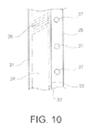
- Figures 9 and 10 are top views of a detail in Figure 8 according to two embodiments.
- a drum to receive the laundry to be washed and/or dried is generally indicated with the reference numeral 1.
- the drum 1 comprises a side wall 2, a rear or bottom wall 3, and a front wall 4.
- the walls 2, 3 and 4 define an inner space 6 which is intended to receive the laundry to be washed and/or dried.
- the drum 1 front wall 4 is a stainless steel or plastic ring, with a generally circular-shaped opening 5 arranged at the opening of a washing machine washing tub (not shown in the Figures), for accessing the inner space 6 in order to perform the laundry loading and unloading.
- the drum 1 rear wall 3 is preferably a steel disk substantially planar and centrally drawn, with concavity facing the drum outside.
- a supporting hub 7 for the same drum is mounted, through which the drum is operatively connected to motor means (not shown), which control the rotation thereof around a rotational axis X.
- the drum side wall 2 is preferably obtained from a generally planar steel plate 8 (the so-called band), which is so folded as to generate a approximately rotational surface around a longitudinal central axis, in use, coincident with the rotational axis X.
- the coupling of the rear 3 and front 4 walls to the side wall 2 is preferably implemented by folding two longitudinal edges 9, 10 of the band 8 constituting the side wall 2, so as to provide, at the two longitudinal edges 9, 10, a profile, for example a C-shaped profile.
- the rear 3 and front 4 walls are so shaped as to define, at the respective outer edges 11, 12, profiles which are complementary to the C-shaped profile formed at the side wall 2 two longitudinal edges 9, 10 in order to obtain a shape-connection between the side wall 2 and the rear 3 and front 4 walls.
- the band 8 further comprises a first end 13 and a second end 14, which are mutually connected along a seam 15, so as to impart a looped shape to the side wall 2.
- the first end 13 comprises a first connecting flap 16 defined by a first folding 17 which is substantially parallel to the seam 15 and a free edge 18 of the first end 13.
- the second end 14 comprises a second connecting flap 19 defined by a second folding 20 which is substantially parallel to the seam 15 and a free edge 21 of said second end 14.
- the first flap 16 and the second flap 19 are folded towards the outside of the drum 1 (that is, towards the side wall 2 outer side), and adhere one another, so that the mutually adjacent first 17 and second 20 foldings form a transition zone 22 of the side wall 2 inner surface 23.
- the first connecting flap 16 comprises a first length 24 adjacent to the first folding 17 and adhering to the second flap 19, as well as a second length 25 arranged between the first length 24 and the first end 13 free edge 18, and extending past the second flap 19 free edge 21.
- the first connecting flap 16 must have a higher length (transversal relative to the seam 15) than the second connecting flap 19 length ( Figure 6 ).
- the first 16 and the second 19 connecting flaps are folded from the outside of the drum 1 or the side wall 2 towards the side of the side wall 2 second end 14, so that the first connecting flap 16 completely covers the second connecting flap 19 from the outside (see, for example, Figures 7, 8 ) .
- first connecting means are provided, for example, one or more first weldings 26, between the first flap 16 first length 24 and the second flap 19, and second connecting means distinct and spaced from said first connecting means, for example, one or more second weldings 27 between the first flap 16 second length 25 and a zone 28 of the second end 14 distinct and spaced from the second connecting flap 19.
- first connecting means for example, one or more first weldings 26, between the first flap 16 first length 24 and the second flap 19, and second connecting means distinct and spaced from said first connecting means, for example, one or more second weldings 27 between the first flap 16 second length 25 and a zone 28 of the second end 14 distinct and spaced from the second connecting flap 19.
- the zone 28 ca be arranged on the side of the second folding 20 opposite the second connecting flap 19.
- the side wall seam results to be particularly resistant, smooth, and aesthetically pleasant (particularly from the inside of the drum) and not much bulky towards the outside of the drum.
- the first 16 and second 19 connecting flaps are folded towards the side wall 2 second end 14, so that the first flap 16 first length 24 and the second flap 19 connected thereto are parallel and adherent to the side wall 2 outer surface 29 at the second end 14 thereof.
- the first flap 16 can comprises a first auxiliary folding 30 adjacent and substantially parallel to the first folding 17 and with an opposite curvature, so as to obtain a step 31 between the level of the side wall 2 and the level of the first connecting length 24 of the first flap 16.
- the first connecting flap 16 comprises two further substantially parallel and adjacent auxiliary foldings 32, 33 which create a further step between the above-mentioned first length 24 and second length 25, so that the second length 25 also adheres in parallel to the zone 28 of the side wall 2 to which it is connected.
- first 26 and second 27 connecting means can be selected from the group containing:
- - weldings continuous, discrete, extended on an area, wire- or spot-shaped, preferably laser welding, continuous bead welding, or via discrete spots or lengths; and/or
- the junction results to be mechanically very resistant and durable.
- junction configuration between the two ends 13, 14 allows a good alignment and closing up of the first and second foldings, thereof, it allows obtaining a particularly smooth and planar transition zone of the side wall inner surface (compared to the prior art solutions).
- the side wall 2 has a first and a second sections (e.g. cylindrical, frusto-conical, or generally shaped as a revolving body) which are axially adjacent and differently shaped, and the seam 15 is extended in both sections and it is covered by the dragging blade 34 in the first section, preferably in a rear section which is exposed in the second section, preferably a front one.
- a first and a second sections e.g. cylindrical, frusto-conical, or generally shaped as a revolving body
- the side wall 2 is advantageously obtained by cutting the band 8 from a steel plate, in which the two transversal edges forming the band 8 ends 13, 14 are rectangular or inclined relative to the longitudinal edges 9, 10, and preferably mutually parallel or, more generally, complementary. This advantageously allows to cut the bands 8 from a plate without waste.
- the drum could be provided with reinforcing ribs (not shown), preferably substantially transversal and overlapped to the seam 15.
- reinforcing ribs can be obtained by drawing the connection zone provided before.
- the drum 1 preferably comprises at least one dragging blade 34 with a base portion 35 secured to the side wall 2 inner surface 23, and a dragging portion 36 projecting into the drum inner space 6.
- the dragging blade 34 is arranged in the connection zone of the band 8 two ends 13, 14, so that the base portion 35 at least partially covers the seam 15.
- the drum 1 comprises three dragging blades, one of which (inclined or, alternatively, parallel to the rotational axis X) covers such seam 15 by means of the base portion 35 thereof.
- the present invention also relates to a method to obtain the drum 1 for washing, washing/drying, or drying machine.
- the first 13 and second 14 ends are connected one another along the seam 15, so as to impart a looped shape to the side wall 2.
- the first end 13 is folded towards the outside of the drum 1 along a first folding line 17 which is substantially parallel to the future seam 15 to be obtained.
- the first connecting flap 16 is obtained, which results to be defined by the first folding line 17 and the first end 13 free edge 18.
- the second end 14 is folded towards the outside of the drum 1 along a second folding line 20 which is parallel to the future seam 15 to be obtained.
- the second connecting flap 19 is obtained, which results to be defined by the second folding 20 and the second end 14 free edge 21.
- the projecting connection edges do not have the same length; instead, the first connecting flap has a higher length than the second edge.
- the first connecting flap 16 is arranged adjacent to and aligned with the second connecting flap 19, so that the first and the second 17, 20 foldings are mutually adjacent and form a transition zone 22 of the side wall 2 inner surface 23.
- the first flap 16 first length 24 is adjacent to the second flap 19, and a second length 25 of the first flap 16 extends past the second connecting flap 19 free edge 21.
- first edge first length 24 is connected to the second flap 19 by first connecting means, preferably by a first welding and, subsequently, the first 16 and second 19 edges are folded together from the outside of the drum towards the side of the side wall 2 second end 14, so that the first edge completely covers the second edge (as seen from the outside of the drum).
- first connecting flap 16 second length 25 is connected to a zone 28 of the second end 14 which is distinct and spaced from the second connecting flap 19 by second connecting means, for example, by a second welding 27, which means are distinct and spaced from the first connecting means 26.
- the longitudinal opposite edges 9, 10 of the band 8 can be connected to the respective outer edges of the front and rear walls according to the manner described above.
Landscapes
- Engineering & Computer Science (AREA)
- Mechanical Engineering (AREA)
- Textile Engineering (AREA)
- Main Body Construction Of Washing Machines And Laundry Dryers (AREA)
Abstract
Description
- The present invention relates to a drum for a washing, drying, or washing/drying machine.
- With reference in particular to the known washing machines, the perforated drum intended to receive the laundry to be washed is rotatably arranged inside a liquor-containing tub. Thanks to the rotational movement of the drum, the laundry is stirred and whirled in the liquor, and the same liquor is pulled by the rotating drum upwards, from where it falls on the laundry, which results to be completely impregnated and soaked, so as to transfer impurities to the washing and rinsing liquor.
- The drum is typically composed of a rear wall, by means of which the drum is secured in the washing machine, a front wall defining a loading port through which it is possible to access the drum inside, and a side wall which is typically cylindrical and perforated so as to allow the liquor exchange between the tub and the drum inside. The side wall is typically obtained from a rectangular steel plate, with two opposite longitudinal edges and two opposite transversal edges, which is bent around a drum longitudinal axis in order to create such cylinder, and the transversal edges of which are connected one another in order to maintain the cylindrical shape, while the longitudinal edges are connected to respective outer edges of the rear and front walls to create the drum.
- In order to increase the washing and drying efficiency for the laundry hold in the drum, the latter is exposed to higher and higher laundry loads (both due to a volume increase of the same drum, and due to an increase in the laundry mass which can be loaded in a preset drum volume) and to higher and higher rotational rates, and to more and more abrupt reversals of the rotation direction. Such operative conditions of the modern washing and drying machines involve, particularly during tumble drying, high centrifugal forces and radial impacts acting on the drum side wall undergoing dynamical stresses and strains, requiring that both the same side wall, and the connection between the transversal edges thereof are so sized as to be very robust.
- Particularly, in those drums having a high volume and diameter, the side wall seam constitutes the weakest link from the point of view of the drum structural strength, and it may limit the performance thereof as regards load mass and revolution number.
- Furthermore, the side wall seam constitutes a drum surface discontinuity, with potentially adverse effects on the laundry (friction, fabric wear, risk for fabrics of getting entangled at the seam plate edge) and generally aesthetically unacceptable effects.
- In order to obviate these drawbacks, it is known to cover the side wall seam by means of a dragging blade which is secured to the side wall above the seam.
- However, in the modern washing, washing/drying, and drying machines, the laundry drum may have a variable shape along the drum rotational axis, for example, a stepped shape, or a shape with different expansion areas. In such cases, it can be desirable to use shorter dragging blades, which do not extend along the whole drum depth, therefore which cannot cover the whole wall seam.
- Therefore, the object of the present invention is to devise a drum for a washing, drying, or washing/drying machine, having a high mechanical strength, and which is suitably used with short dragging blades.
- A further object of the present invention is to propose a method for the manufacturing of a laundry drum for a washing, drying, or washing/drying machine having such characteristics as to obviate the drawbacks cited with reference to the prior art.
- These and other objects are achieved by a drum for washing, drying, or washing/drying machines, comprising a bottom wall, a front wall opposite the bottom wall, and a side wall extending around a drum rotational axis, and comprising two longitudinal opposite edges connected to respective outer edges of the front and rear walls, as well as first and second ends mutually connected along a seam, so as to impart a looped shape to the side wall, in which:
- - said first end comprises a first connecting flap defined by a first folding which is substantially parallel to the seam, and a free edge of said first end;
- - said second end comprises a second connecting flap defined by a second folding which is substantially parallel to the seam, and a free edge of said second end;
- - said first flap and said second flap are folded towards the drum outside, and adhere one another, so that said first and said second mutually adjacent foldings form a transition zone of the side wall inner surface;
- - said first flap comprises a first length adjacent to said first folding and adherent to the second flap, and a second length arranged between said first length and the first end free edge, and extended past the second flap free edge;
- - said first and second flaps are folded from the drum outside to the side of the side wall second end, so that said first flap completely cover said second flap (as seen from the external part of the drum);
- - first connecting means connect the first flap first length with the second flap, and second connecting means, which are distinct and spaced from said first connecting means, connect said first flap second length to a zone of said second end which is distinct and spaced from said second connecting flap.
- Thanks to this particular configuration of the drum, the side wall junction results to be particularly resistant, smooth, and aesthetically pleasant as seen from inside the drum and not much bulky as seen from outside the drum.
- Advantageous embodiments are the object of the dependant claims.
- The above-mentioned objects are further achieved by a method to obtain a drum for washing, washing/drying, or drying machine, in which said drum comprises a bottom wall, a front wall opposite the bottom wall, and a side wall extending around a drum rotational axis,
- said method comprising the steps of:
- - providing said bottom wall and said front wall;
- - providing said side wall by creating a stainless steel band with two opposite longitudinal edges and first and second ends;
- - connecting said opposite longitudinal edges of said band with respective outer edges of the front and rear walls;
- - mutually connecting said first and second ends along a seam, so as to impart a looped shape to the side wall;
- - in which the step of connecting the side wall first and second ends comprises the steps of:
- - folding the first end towards the drum outside along a first folding line which is substantially parallel to the seam, so as to create a first connecting flap defined by said first folding and a free edge of said first end;
- - folding the second end towards the drum outside along a second folding line which is substantially parallel to the seam, so as to create a second connecting flap defined by said second folding and a free edge of said second end;
- - creating said first connecting flap and said second connecting flap so that said first flap is longer than said second flap;
- - positioning said first connecting flap adjacently and in alignment with said second connecting flap, so that said first and said second foldings are mutually adjacent and form a transition zone of the inner surface of the side wall, and which a first flap first length is adjacent to the second flap, and a first flap second length extends past the second connecting flap free edge;
- - connecting the first flap first length to the second flap by first connecting means;
- - folding said first and second flaps from the drum outside towards the side of the side wall second end, so that said first flap completely covers said second flap (as seen from the outside of the drum);
- - connecting said first flap second length to a zone of said second end which is distinct and spaced from said second connecting flap by second connecting means which are distinct and spaced from said first connecting means.
- Advantageous embodiments of the method are the object of the dependant claims.
- The above-mentioned objects are further achieved by a laundry drum implemented by means of the above-mentioned method.
- In order to better understand the invention, and appreciate the advantages thereof, some non-limiting, exemplary embodiments will be described herein below, with reference to the annexed Figures, in which:
-
Figure 1 is a schematic side view of a drum according to an embodiment of the invention; -
Figure 2 shows the side wall of the drum inFigure 1 which is laid in a hypothetical laying plane; -
Figure 3 shows a plate band which has been cut and perforated in order to obtain the side wall of the drum inFigure 1 ; -
Figure 4 is a cross-sectional view of the drum side wall in accordance with an embodiment; -
Figure 5 is a cross-sectional view of the side wall of the drum in accordance with a further embodiment of the invention; -
Figures 6, 7 and 8 are sectional views of the drum side wall which illustrate steps to obtain the drum according to an embodiment of the invention; -
Figures 9 and10 are top views of a detail inFigure 8 according to two embodiments. - With reference to the Figures, a drum to receive the laundry to be washed and/or dried is generally indicated with the reference numeral 1. The drum 1 comprises a
side wall 2, a rear or bottom wall 3, and a front wall 4. Thewalls 2, 3 and 4 define aninner space 6 which is intended to receive the laundry to be washed and/or dried. The drum 1 front wall 4 is a stainless steel or plastic ring, with a generally circular-shaped opening 5 arranged at the opening of a washing machine washing tub (not shown in the Figures), for accessing theinner space 6 in order to perform the laundry loading and unloading. - The drum 1 rear wall 3 is preferably a steel disk substantially planar and centrally drawn, with concavity facing the drum outside. Centrally to the drum 1 rear wall 3, a supporting hub 7 for the same drum is mounted, through which the drum is operatively connected to motor means (not shown), which control the rotation thereof around a rotational axis X.
- The
drum side wall 2 is preferably obtained from a generally planar steel plate 8 (the so-called band), which is so folded as to generate a approximately rotational surface around a longitudinal central axis, in use, coincident with the rotational axis X. - The coupling of the rear 3 and front 4 walls to the
side wall 2 is preferably implemented by folding twolongitudinal edges 9, 10 of theband 8 constituting theside wall 2, so as to provide, at the twolongitudinal edges 9, 10, a profile, for example a C-shaped profile. The rear 3 and front 4 walls are so shaped as to define, at the respectiveouter edges 11, 12, profiles which are complementary to the C-shaped profile formed at theside wall 2 twolongitudinal edges 9, 10 in order to obtain a shape-connection between theside wall 2 and the rear 3 and front 4 walls. - The
band 8 further comprises afirst end 13 and asecond end 14, which are mutually connected along aseam 15, so as to impart a looped shape to theside wall 2. - According to an aspect of the invention, the
first end 13 comprises a first connectingflap 16 defined by afirst folding 17 which is substantially parallel to theseam 15 and afree edge 18 of thefirst end 13. Thesecond end 14 comprises a second connectingflap 19 defined by asecond folding 20 which is substantially parallel to theseam 15 and afree edge 21 of saidsecond end 14. Thefirst flap 16 and thesecond flap 19 are folded towards the outside of the drum 1 (that is, towards theside wall 2 outer side), and adhere one another, so that the mutually adjacent first 17 and second 20 foldings form atransition zone 22 of theside wall 2inner surface 23. The first connectingflap 16 comprises afirst length 24 adjacent to thefirst folding 17 and adhering to thesecond flap 19, as well as asecond length 25 arranged between thefirst length 24 and thefirst end 13free edge 18, and extending past thesecond flap 19free edge 21. in this regard, the first connectingflap 16 must have a higher length (transversal relative to the seam 15) than the second connectingflap 19 length (Figure 6 ). - The first 16 and the second 19 connecting flaps are folded from the outside of the drum 1 or the
side wall 2 towards the side of theside wall 2second end 14, so that the first connectingflap 16 completely covers the second connectingflap 19 from the outside (see, for example,Figures 7, 8 ) . - For the connection of the
ends first weldings 26, between thefirst flap 16first length 24 and thesecond flap 19, and second connecting means distinct and spaced from said first connecting means, for example, one or moresecond weldings 27 between thefirst flap 16second length 25 and azone 28 of thesecond end 14 distinct and spaced from the second connectingflap 19. Particularly, thezone 28 ca be arranged on the side of thesecond folding 20 opposite the second connectingflap 19. - Thanks to this configuration of the drum, the side wall seam results to be particularly resistant, smooth, and aesthetically pleasant (particularly from the inside of the drum) and not much bulky towards the outside of the drum.
- In accordance with an embodiment, the first 16 and second 19 connecting flaps are folded towards the
side wall 2second end 14, so that thefirst flap 16first length 24 and thesecond flap 19 connected thereto are parallel and adherent to theside wall 2outer surface 29 at thesecond end 14 thereof. To this aim, thefirst flap 16 can comprises a firstauxiliary folding 30 adjacent and substantially parallel to thefirst folding 17 and with an opposite curvature, so as to obtain astep 31 between the level of theside wall 2 and the level of the first connectinglength 24 of thefirst flap 16. - In accordance with an embodiment, the first connecting
flap 16 comprises two further substantially parallel and adjacentauxiliary foldings first length 24 andsecond length 25, so that thesecond length 25 also adheres in parallel to thezone 28 of theside wall 2 to which it is connected. - With reference to the first 26 and second 27 connecting means, according to the specific embodiment, they can be selected from the group containing:
- - weldings (continuous, discrete, extended on an area, wire- or spot-shaped), preferably laser welding, continuous bead welding, or via discrete spots or lengths; and/or
- - rivets (single rivets, or in sets);
- - indentations;
- - glue works (continuous, discrete, wire- or spot-shaped);
- - local folded seams (discrete or continuous) .
- In this manner, a very compact junction is obtained, with reduced radial dimensions (relative to the drum 1 rotational axis), and in particular in which the weldings result to be sufficiently protected against corrosive agents contained in the liquor.
- Furthermore, thanks to the provision of two independent weldings connecting distinct and spaced zones of the
side wall 2 two ends, the junction results to be mechanically very resistant and durable. - Finally, the junction configuration between the two ends 13, 14 allows a good alignment and closing up of the first and second foldings, thereof, it allows obtaining a particularly smooth and planar transition zone of the side wall inner surface (compared to the prior art solutions).
- This markedly improves the esthetical impact of the junction, and also the interaction thereof with the laundry items contained in the drum 1, thus obviating the need to cover the whole seam by means of very long dragging blades.
- Thereby, it is possible to use dragging
blades 34 having a length which is lesser than the drum length, and, therefore, to economize and promote the manufacturing of variable cross-section drums. - In accordance with an embodiment, the
side wall 2 has a first and a second sections (e.g. cylindrical, frusto-conical, or generally shaped as a revolving body) which are axially adjacent and differently shaped, and theseam 15 is extended in both sections and it is covered by thedragging blade 34 in the first section, preferably in a rear section which is exposed in the second section, preferably a front one. - With reference to the Figures, the
side wall 2 is advantageously obtained by cutting theband 8 from a steel plate, in which the two transversal edges forming theband 8 ends 13, 14 are rectangular or inclined relative to thelongitudinal edges 9, 10, and preferably mutually parallel or, more generally, complementary. This advantageously allows to cut thebands 8 from a plate without waste. - In order to further increase the seam mechanical strength, the drum could be provided with reinforcing ribs (not shown), preferably substantially transversal and overlapped to the
seam 15. Advantageously, such reinforcing ribs can be obtained by drawing the connection zone provided before. - As already stated before, the drum 1 preferably comprises at least one
dragging blade 34 with abase portion 35 secured to theside wall 2inner surface 23, and a draggingportion 36 projecting into the druminner space 6. Advantageously, thedragging blade 34 is arranged in the connection zone of theband 8 two ends 13, 14, so that thebase portion 35 at least partially covers theseam 15. - In accordance with an embodiment, the drum 1 comprises three dragging blades, one of which (inclined or, alternatively, parallel to the rotational axis X) covers
such seam 15 by means of thebase portion 35 thereof. - The present invention also relates to a method to obtain the drum 1 for washing, washing/drying, or drying machine.
- After preparing the bottom wall 3 and the front wall 4, and providing the
side wall 2, for example, by cutting thestainless steel plate 8 with the two oppositelongitudinal edges 9, 10 and the above-mentioned first 13 and second 14 ends, the first 13 and second 14 ends are connected one another along theseam 15, so as to impart a looped shape to theside wall 2. In particular, thefirst end 13 is folded towards the outside of the drum 1 along afirst folding line 17 which is substantially parallel to thefuture seam 15 to be obtained. Thereby, the first connectingflap 16 is obtained, which results to be defined by thefirst folding line 17 and thefirst end 13free edge 18. - Similarly, the
second end 14 is folded towards the outside of the drum 1 along asecond folding line 20 which is parallel to thefuture seam 15 to be obtained. Thereby, the second connectingflap 19 is obtained, which results to be defined by thesecond folding 20 and thesecond end 14free edge 21. - As may be seen in the Figures, the projecting connection edges do not have the same length; instead, the first connecting flap has a higher length than the second edge.
- The first connecting
flap 16 is arranged adjacent to and aligned with the second connectingflap 19, so that the first and the second 17, 20 foldings are mutually adjacent and form atransition zone 22 of theside wall 2inner surface 23. In this configuration, thefirst flap 16first length 24 is adjacent to thesecond flap 19, and asecond length 25 of thefirst flap 16 extends past the second connectingflap 19free edge 21. - In this position, the first edge
first length 24 is connected to thesecond flap 19 by first connecting means, preferably by a first welding and, subsequently, the first 16 and second 19 edges are folded together from the outside of the drum towards the side of theside wall 2second end 14, so that the first edge completely covers the second edge (as seen from the outside of the drum). - During or after the first and second edges folding, the first connecting
flap 16second length 25 is connected to azone 28 of thesecond end 14 which is distinct and spaced from the second connectingflap 19 by second connecting means, for example, by asecond welding 27, which means are distinct and spaced from the first connectingmeans 26. - The longitudinal
opposite edges 9, 10 of theband 8 can be connected to the respective outer edges of the front and rear walls according to the manner described above. - Further advantageous characteristics and embodiments of the method have already been described before, with reference to the
drum 2 and, in order to avoid repetitions, the previous description of the drum is to be considered as an integral parte of the description of the method for the implementation thereof. - It should be apparent that those skilled in the art, aiming at meeting specific, contingent needs, will be able to carry out further modifications and variations to the laundry drum and the method for manufacturing the laundry drum according to the present invention, all of which however falling within the scope of protection of the invention, as defined by the following claims.
Claims (14)
- A drum (1) for washing, washing/drying, or drying machines, comprising a rear wall (3), a front wall (4) opposite the rear wall (3), and a side wall (2) extending around a rotational axis (X) of the drum (1), and comprising two opposite longitudinal edges (9, 10) connected to respective outer edges (11, 12) of the front (4) and rear (3) walls, as well as first (13) and second (14) ends connected one another via a seam (15) so as to impart a looped shape to the side wall (2), in which:- said first end (13) comprises a first connecting flap (16) defined by a first folding (17) substantially parallel to the seam (15), and a free edge (18) of said first end (13);- said second end (14) comprises a second connecting flap (19) defined by a second folding (20) substantially parallel to the seam (15), and a free edge (21) of said second end (14);- said first flap (16) and said second flap (19) are folded towards the outside of the drum (1) and adhere one another, so that said mutually adjacent first (17) and said second (20) foldings form a transition zone (22) of the side wall (2) inner surface (23);- said first flap (16) comprises a first length (24) adjacent to said first folding (17) and adherent to the second flap (19), and a second length (25) arranged between said first length (24) and the first end (13) free edge (18), and extended past the second flap (19) free edge (21);- said first and second flaps (16, 19) are folded from the outside of the drum towards the side of the side wall (2) second end (14), so that said first flap (16) completely covers said second flap (19);- first connecting means (26) connect the first flap (16) first length (24) to the second flap (19), and second connecting means (27), which are distinct and spaced from said first connecting means (26), connect said first flap (16) second length (25) to a zone (28) of said second end (14) which is distinct and spaced from said second connecting flap (19).
- The drum according to claim 1, wherein said first connecting flap (16) and second connecting flap (19) are folded towards the side wall (2) second end (14), so that the first flap (16) first length (24) and the second flap (19) connected thereto are parallel and adherent to the side wall (2) outer surface (29) at the second end (14) thereof.
- The drum according to claim 1 or 2, wherein said first flap (16) comprises a first auxiliary folding (30) adjacent and parallel to said first folding (17) and having an opposite curvature, such as to obtain a step (31) between the side wall (2) and the first flap (16) first connecting length (24).
- The drum according to any preceding claim, wherein the first connecting flap (16) comprises two further substantially parallel and adjacent auxiliary foldings (32, 33) which create a step between said first length (24) and second length (25), so that the second length (25) adheres in parallel to the zone (28) of the side wall (2) to which it is connected.
- The drum according to any preceding claim, wherein said first connecting means (26) and second connecting means (27) comprise connection systems or elements selected from the group containing:- weldings; and/or- rivets;- indentations;- local folded seams.
- The drum according to any preceding claim, wherein said first and said second foldings are aligned and approximated, so as to create an substantially smooth and planar transition zone of the side wall inner surface.
- The drum according to any preceding claim, comprising one or more dragging blades (34), one of which having a lesser length than the drum (1) depth only partially covers said seam (15), so that a seam portion is exposed to the inside of the drum (1).
- The drum according to the preceding claim, wherein said side wall (2) has axially adjacent and differently shaped first and second sections, and said seam (15) is extended in both sections and is covered by said dragging blade (34) in said first section and is exposed in said second section.
- The drum according to any preceding claim, comprising reinforcing ribs, which are transversal and overlapping the seam (15).
- The drum according to the preceding claim, wherein said reinforcing ribs are obtained by drawing, or punching, or similar cold deformation, of the seam (15) zone obtained before.
- Method for obtaining a laundry drum (1) for washing, washing/drying, or drying machine, wherein said drum comprises a bottom wall, a front wall opposite the bottom wall, and a side wall extending around a drum rotational axis, said method comprising the steps of:- providing said bottom wall and said front wall;- providing said side wall by forming a metal band with two longitudinal opposite edges and first and second ends;- connecting said longitudinal opposite edges of said band with respective outer edges of the front and rear walls;- mutually connecting said first and second ends along a seam, so as to impart a looped shape to the side wall,characterized in that the step of connecting the side wall first and the second ends comprises the steps of:- folding the first end towards the outside of the drum along a first folding line which is substantially parallel to the seam, so as to create a first connecting flap defined by said first folding and a free edge of said first end;- folding the second end towards the outside of the drum along a second folding line which is substantially parallel to the seam, so as to create a second connecting flap defined by said second folding and a free edge of said second end;- creating said first connecting flap and said second connecting flap so that said first flap is longer than said second flap;- positioning said first connecting flap adjacently and in alignment with said second connecting flap, so that said first and said second foldings are mutually adjacent and form a transition zone of the side wall inner surface, and that a first flap first length is adjacent to the second flap, and a first flap second length extends past the second connecting flap free edge;- connecting the first flap first length to the second flap by first connecting means;- folding said first and second flaps from the outside of the drum towards the side of the side wall second end, so that said first flap completely covers said second flap;- connecting said first flap second length to a zone of said second end which is distinct and spaced from said second connecting flap via second connecting means which are distinct and spaced from said first connecting means.
- The method according to claim 11, comprising the steps of:- folding said first flap such as to obtain a first auxiliary folding (30) adjacent and parallel to said first folding (17) and having an opposite curvature, such as to create a step (31) between the side wall (2) and the first flap (16) first connecting length (24);- folding said first flap such as to create two further auxiliary foldings (32, 33) substantially parallel and adjacent which create a step between said first length (24) and second length (25), so that the second length (25) adheres in parallel to the zone (28) of the side wall (2) to which it is connected.
- The method according to claim 11 or 12, wherein said first connecting means (26) and second connecting means (27) comprise connection systems or elements selected from the group containing:- weldings; and/or- rivets;- indentations;- local folded seams.
- The method according to claim 11 or one of the successive claims, comprising the step of creating reinforcing ribs which are transversal and overlapping the seam (15) by means of drawing or punching, or similar cold deformation of the seam (15) zone created before.
Priority Applications (2)
| Application Number | Priority Date | Filing Date | Title |
|---|---|---|---|
| DE200860005743 DE602008005743D1 (en) | 2008-09-24 | 2008-09-24 | Washing drum, washing, drying, drying and the like |
| EP20080425629 EP2169103B1 (en) | 2008-09-24 | 2008-09-24 | Drum for washing, washing/drying, drying machine and the like |
Applications Claiming Priority (1)
| Application Number | Priority Date | Filing Date | Title |
|---|---|---|---|
| EP20080425629 EP2169103B1 (en) | 2008-09-24 | 2008-09-24 | Drum for washing, washing/drying, drying machine and the like |
Publications (2)
| Publication Number | Publication Date |
|---|---|
| EP2169103A1 true EP2169103A1 (en) | 2010-03-31 |
| EP2169103B1 EP2169103B1 (en) | 2011-03-23 |
Family
ID=40380663
Family Applications (1)
| Application Number | Title | Priority Date | Filing Date |
|---|---|---|---|
| EP20080425629 Ceased EP2169103B1 (en) | 2008-09-24 | 2008-09-24 | Drum for washing, washing/drying, drying machine and the like |
Country Status (2)
| Country | Link |
|---|---|
| EP (1) | EP2169103B1 (en) |
| DE (1) | DE602008005743D1 (en) |
Citations (2)
| Publication number | Priority date | Publication date | Assignee | Title |
|---|---|---|---|---|
| EP0395859A1 (en) * | 1989-05-02 | 1990-11-07 | BOSCH-SIEMENS HAUSGERÄTE GmbH | Washing machine drum |
| DE102006007066A1 (en) * | 2006-02-15 | 2007-08-16 | BSH Bosch und Siemens Hausgeräte GmbH | Washing laundry drum |
-
2008
- 2008-09-24 EP EP20080425629 patent/EP2169103B1/en not_active Ceased
- 2008-09-24 DE DE200860005743 patent/DE602008005743D1/en active Active
Patent Citations (2)
| Publication number | Priority date | Publication date | Assignee | Title |
|---|---|---|---|---|
| EP0395859A1 (en) * | 1989-05-02 | 1990-11-07 | BOSCH-SIEMENS HAUSGERÄTE GmbH | Washing machine drum |
| DE102006007066A1 (en) * | 2006-02-15 | 2007-08-16 | BSH Bosch und Siemens Hausgeräte GmbH | Washing laundry drum |
Also Published As
| Publication number | Publication date |
|---|---|
| EP2169103B1 (en) | 2011-03-23 |
| DE602008005743D1 (en) | 2011-05-05 |
Similar Documents
| Publication | Publication Date | Title |
|---|---|---|
| EP2000574B1 (en) | Rotating tub body and drum-type washing machine having the same | |
| US20070214630A1 (en) | Method for manufacturing drum and washing machine using the drum | |
| US7752872B2 (en) | Basket for washing machine, washer-dryer, dryer and the like | |
| US8833112B2 (en) | Stator of motor and washing apparatus having the same | |
| US7395684B2 (en) | Drum | |
| CN103132278B (en) | Washing machine | |
| EP1498536A2 (en) | Drum-type washing machine | |
| US5802886A (en) | Spin basket for a washing machine | |
| EP2169103B1 (en) | Drum for washing, washing/drying, drying machine and the like | |
| US6935143B2 (en) | Washing-machine laundry drum | |
| CN101619533A (en) | Drum-type washing and drying machine | |
| KR102711550B1 (en) | Washing machine and manufacturing method thereof | |
| CN201080559Y (en) | Washing machine cylindrical washer | |
| EP1760183B1 (en) | Washing and/or Drying Machine Having a Damper Connecting Structure Including a Reinforcing Portion | |
| CN101109142B (en) | Drum-type washing machine | |
| KR100575200B1 (en) | Drum Type Washing Machine | |
| EP3899124B1 (en) | A laundry washer-dryer having a tub with improved mechanical strength | |
| KR100987433B1 (en) | Tub structure of drum washing machine | |
| WO2019132811A1 (en) | A washer-dryer comprising a flange | |
| EP2761074B1 (en) | A drum and the production method thereof | |
| US20050204559A1 (en) | Expanded clamping band for washer | |
| EP3562982B1 (en) | A drum and its production method | |
| WO2020076165A1 (en) | Laundry washing machine drum containment |
Legal Events
| Date | Code | Title | Description |
|---|---|---|---|
| PUAI | Public reference made under article 153(3) epc to a published international application that has entered the european phase |
Free format text: ORIGINAL CODE: 0009012 |
|
| AK | Designated contracting states |
Kind code of ref document: A1 Designated state(s): AT BE BG CH CY CZ DE DK EE ES FI FR GB GR HR HU IE IS IT LI LT LU LV MC MT NL NO PL PT RO SE SI SK TR |
|
| AX | Request for extension of the european patent |
Extension state: AL BA MK RS |
|
| 17P | Request for examination filed |
Effective date: 20100709 |
|
| GRAP | Despatch of communication of intention to grant a patent |
Free format text: ORIGINAL CODE: EPIDOSNIGR1 |
|
| AKX | Designation fees paid |
Designated state(s): DE GB IT |
|
| GRAS | Grant fee paid |
Free format text: ORIGINAL CODE: EPIDOSNIGR3 |
|
| GRAA | (expected) grant |
Free format text: ORIGINAL CODE: 0009210 |
|
| AK | Designated contracting states |
Kind code of ref document: B1 Designated state(s): DE GB IT |
|
| REG | Reference to a national code |
Ref country code: GB Ref legal event code: FG4D |
|
| REF | Corresponds to: |
Ref document number: 602008005743 Country of ref document: DE Date of ref document: 20110505 Kind code of ref document: P |
|
| REG | Reference to a national code |
Ref country code: DE Ref legal event code: R096 Ref document number: 602008005743 Country of ref document: DE Effective date: 20110505 |
|
| PLBE | No opposition filed within time limit |
Free format text: ORIGINAL CODE: 0009261 |
|
| STAA | Information on the status of an ep patent application or granted ep patent |
Free format text: STATUS: NO OPPOSITION FILED WITHIN TIME LIMIT |
|
| 26N | No opposition filed |
Effective date: 20111227 |
|
| REG | Reference to a national code |
Ref country code: DE Ref legal event code: R097 Ref document number: 602008005743 Country of ref document: DE Effective date: 20111227 |
|
| PGFP | Annual fee paid to national office [announced via postgrant information from national office to epo] |
Ref country code: DE Payment date: 20200928 Year of fee payment: 13 Ref country code: GB Payment date: 20200922 Year of fee payment: 13 |
|
| PGFP | Annual fee paid to national office [announced via postgrant information from national office to epo] |
Ref country code: IT Payment date: 20200907 Year of fee payment: 13 |
|
| REG | Reference to a national code |
Ref country code: DE Ref legal event code: R119 Ref document number: 602008005743 Country of ref document: DE |
|
| GBPC | Gb: european patent ceased through non-payment of renewal fee |
Effective date: 20210924 |
|
| PG25 | Lapsed in a contracting state [announced via postgrant information from national office to epo] |
Ref country code: GB Free format text: LAPSE BECAUSE OF NON-PAYMENT OF DUE FEES Effective date: 20210924 Ref country code: DE Free format text: LAPSE BECAUSE OF NON-PAYMENT OF DUE FEES Effective date: 20220401 |
|
| PG25 | Lapsed in a contracting state [announced via postgrant information from national office to epo] |
Ref country code: IT Free format text: LAPSE BECAUSE OF NON-PAYMENT OF DUE FEES Effective date: 20210924 |