EP2168870A2 - Breather apparatus on electromechanical actuators for aircraft landing gear systems - Google Patents
Breather apparatus on electromechanical actuators for aircraft landing gear systems Download PDFInfo
- Publication number
- EP2168870A2 EP2168870A2 EP09170537A EP09170537A EP2168870A2 EP 2168870 A2 EP2168870 A2 EP 2168870A2 EP 09170537 A EP09170537 A EP 09170537A EP 09170537 A EP09170537 A EP 09170537A EP 2168870 A2 EP2168870 A2 EP 2168870A2
- Authority
- EP
- European Patent Office
- Prior art keywords
- housing
- accordance
- actuator system
- actuator
- opening
- Prior art date
- Legal status (The legal status is an assumption and is not a legal conclusion. Google has not performed a legal analysis and makes no representation as to the accuracy of the status listed.)
- Withdrawn
Links
Images


Classifications
-
- F—MECHANICAL ENGINEERING; LIGHTING; HEATING; WEAPONS; BLASTING
- F17—STORING OR DISTRIBUTING GASES OR LIQUIDS
- F17D—PIPE-LINE SYSTEMS; PIPE-LINES
- F17D1/00—Pipe-line systems
-
- B—PERFORMING OPERATIONS; TRANSPORTING
- B64—AIRCRAFT; AVIATION; COSMONAUTICS
- B64C—AEROPLANES; HELICOPTERS
- B64C25/00—Alighting gear
- B64C25/02—Undercarriages
- B64C25/08—Undercarriages non-fixed, e.g. jettisonable
- B64C25/10—Undercarriages non-fixed, e.g. jettisonable retractable, foldable, or the like
- B64C25/18—Operating mechanisms
- B64C25/24—Operating mechanisms electric
-
- Y—GENERAL TAGGING OF NEW TECHNOLOGICAL DEVELOPMENTS; GENERAL TAGGING OF CROSS-SECTIONAL TECHNOLOGIES SPANNING OVER SEVERAL SECTIONS OF THE IPC; TECHNICAL SUBJECTS COVERED BY FORMER USPC CROSS-REFERENCE ART COLLECTIONS [XRACs] AND DIGESTS
- Y10—TECHNICAL SUBJECTS COVERED BY FORMER USPC
- Y10T—TECHNICAL SUBJECTS COVERED BY FORMER US CLASSIFICATION
- Y10T137/00—Fluid handling
- Y10T137/794—With means for separating solid material from the fluid
-
- Y—GENERAL TAGGING OF NEW TECHNOLOGICAL DEVELOPMENTS; GENERAL TAGGING OF CROSS-SECTIONAL TECHNOLOGIES SPANNING OVER SEVERAL SECTIONS OF THE IPC; TECHNICAL SUBJECTS COVERED BY FORMER USPC CROSS-REFERENCE ART COLLECTIONS [XRACs] AND DIGESTS
- Y10—TECHNICAL SUBJECTS COVERED BY FORMER USPC
- Y10T—TECHNICAL SUBJECTS COVERED BY FORMER US CLASSIFICATION
- Y10T29/00—Metal working
- Y10T29/49—Method of mechanical manufacture
- Y10T29/49002—Electrical device making
-
- Y—GENERAL TAGGING OF NEW TECHNOLOGICAL DEVELOPMENTS; GENERAL TAGGING OF CROSS-SECTIONAL TECHNOLOGIES SPANNING OVER SEVERAL SECTIONS OF THE IPC; TECHNICAL SUBJECTS COVERED BY FORMER USPC CROSS-REFERENCE ART COLLECTIONS [XRACs] AND DIGESTS
- Y10—TECHNICAL SUBJECTS COVERED BY FORMER USPC
- Y10T—TECHNICAL SUBJECTS COVERED BY FORMER US CLASSIFICATION
- Y10T29/00—Metal working
- Y10T29/49—Method of mechanical manufacture
- Y10T29/49826—Assembling or joining
Definitions
- the embodiments described herein relate generally to aircraft landing gear systems and, more particularly, to electromechanical actuator systems used within aircraft landing gear systems.
- At least some known electromechanical actuator systems include a housing that experiences varying pressures and temperatures during a typical flight cycle of an aircraft. For example, during the aircraft ascent, the internal pressure and temperature within the housing decreases as the external pressure and temperature of the surrounding environment decrease until the aircraft is at cruising altitude. Conversely, during the aircraft descent, the internal pressure and temperature within the housing generally increases as the external pressure and temperature of the surrounding environment increases.
- At least some known electromechanical actuator systems balance the internal pressure and temperature within the housing with the external pressure and temperature of the surrounding environment by including an opening in the housing that facilitates venting of air into, and out of, the housing.
- the opening discharges air from the housing through the opening as the external pressure and temperature of the surrounding environment decreases.
- the internal pressure and temperature within the housing are typically low enough that any liquid water within the housing may become frozen.
- air enters the housing through the opening as the external pressure and temperature of the surrounding environment increases. More specifically, when the landing gear bay doors open during landing, the warm, moist air may condense on an actuator mechanism encased within the housing when the actuator mechanism is still cold from the flight. Some condensation may be drawn into the actuator mechanism, and over time, such condensation may cause corrosion, hydrolysis, short circuits, and/or increase an overall mass of the actuator mechanism to the point wherein the actuator mechanism is inoperable.
- At least some known electromechanical actuator systems hermetically seal the actuator mechanism within the housing and use desiccants to facilitate reducing an amount of condensation that can accumulate over an extended period of time.
- sealing the actuator mechanisms within the housing causes a substantial pressure difference to be created between the internal pressure within the housing and the external pressure of the surrounding environment. The increased pressure difference may induce additional strain on the seals of the housing, which may cause premature failure of the seals over time.
- a method for assembling an actuator system includes positioning a housing to encase an actuator within a cavity defined by the housing, and coupling a cap to the housing to facilitate shielding an opening defined in a wall of the housing from a surrounding environment.
- an actuator system in another embodiment, includes a housing and a cap.
- the housing includes a cavity defined by the housing and an opening defined in a wall of the housing.
- the housing encases an actuator within the cavity.
- the cap is coupled to the housing to facilitate shielding the opening from a surrounding environment.
- An electromechanical actuator system includes a housing that maintains its aridity during a course of repeated flight cycles while reducing pressure differences that may be created between an internal pressure within the housing and an external pressure of the surrounding environment is desired.
- maintaining the aridity of the housing facilitates increasing reliability of the actuator mechanism (actuator) encased within the housing, and reducing pressure differences facilitates reducing sealing requirements of the housing and increasing a useful seal life.
- FIG. 1 is a cross-sectional schematic illustration of an exemplary electromechanical actuator system, or EMA, 100 that may be used in an aircraft (not shown).
- EMA 100 includes a moisture pump 110, a protective cap 120, a housing 130, an actuator 140, and a cavity 150.
- Housing 130 includes a moisture pump 110, which is an opening oriented from an internal surface to an external surface of housing 130.
- Protective cap 120 is coupled to housing 130 such that it substantially covers moisture pump 110.
- Actuator 140 is positioned within cavity 150 defined by the internal surface of housing 130.
- housing 130 experiences varying internal pressures and temperatures. For example, during the aircraft ascent, the internal pressure and temperature within housing 130 decreases as the external pressure and temperature of the surrounding environment decrease until the aircraft is at cruising altitude. Conversely, during the aircraft descent, the internal pressure and temperature within housing 130 generally increases as the external pressure and temperature of the surrounding environment increases.
- FIG. 2 is a cross-sectional schematic illustration of EMA 100.
- housing 130 includes a moisture trap 210 and/or a desiccant cartridge 220.
- Moisture trap 210 is a cavity that is defined between moisture pump 110 and cavity 150.
- Desiccant cartridge 220 is a material positioned between moisture pump 110 and cavity 150.
- diffusion inhibition tube 350 is a narrow tube that connects moisture pump 110 to cavity 150 (not shown in Figures 3 and 4 ). Diffusion inhibition tube 350 slows water vapor ingress during steady state ground conditions. More specifically, diffusion inhibition tube 350 has a length that is sized relative to its diameter such that a length-to-diameter ratio of diffusion inhibition tube 350 facilitates reducing a rate of air exchange between the cavity of housing 130 and the surrounding environment. Thus, diffusion inhibition tube 350 facilitates reducing a rate of humidity exchange within housing 130.
- Exemplary embodiments of a breather apparatus on electromechanical actuators for aircraft landing gear systems are described above in detail.
- the methods and systems are not limited to the specific embodiments described herein, but rather, components of systems and/or steps of the methods may be utilized independently and separately from other components and/or steps described herein.
- the methods may also be used in combination with other systems and methods, and are not limited to practice with only the systems and methods as described herein. Rather, the exemplary embodiment can be implemented and utilized in connection with many other applications.
Landscapes
- Engineering & Computer Science (AREA)
- Mechanical Engineering (AREA)
- Aviation & Aerospace Engineering (AREA)
- General Engineering & Computer Science (AREA)
- General Details Of Gearings (AREA)
- Gasket Seals (AREA)
- Motor Or Generator Frames (AREA)
- Sealing Devices (AREA)
- Retarders (AREA)
- Casings For Electric Apparatus (AREA)
- Sealing Using Fluids, Sealing Without Contact, And Removal Of Oil (AREA)
Abstract
Description
- The embodiments described herein relate generally to aircraft landing gear systems and, more particularly, to electromechanical actuator systems used within aircraft landing gear systems.
- At least some known electromechanical actuator systems include a housing that experiences varying pressures and temperatures during a typical flight cycle of an aircraft. For example, during the aircraft ascent, the internal pressure and temperature within the housing decreases as the external pressure and temperature of the surrounding environment decrease until the aircraft is at cruising altitude. Conversely, during the aircraft descent, the internal pressure and temperature within the housing generally increases as the external pressure and temperature of the surrounding environment increases.
- At least some known electromechanical actuator systems balance the internal pressure and temperature within the housing with the external pressure and temperature of the surrounding environment by including an opening in the housing that facilitates venting of air into, and out of, the housing. For example, during aircraft ascent, the opening discharges air from the housing through the opening as the external pressure and temperature of the surrounding environment decreases. At cruising altitudes, the internal pressure and temperature within the housing are typically low enough that any liquid water within the housing may become frozen. During aircraft descent, air enters the housing through the opening as the external pressure and temperature of the surrounding environment increases. More specifically, when the landing gear bay doors open during landing, the warm, moist air may condense on an actuator mechanism encased within the housing when the actuator mechanism is still cold from the flight. Some condensation may be drawn into the actuator mechanism, and over time, such condensation may cause corrosion, hydrolysis, short circuits, and/or increase an overall mass of the actuator mechanism to the point wherein the actuator mechanism is inoperable.
- To address the condensation problem, at least some known electromechanical actuator systems hermetically seal the actuator mechanism within the housing and use desiccants to facilitate reducing an amount of condensation that can accumulate over an extended period of time. However, sealing the actuator mechanisms within the housing causes a substantial pressure difference to be created between the internal pressure within the housing and the external pressure of the surrounding environment. The increased pressure difference may induce additional strain on the seals of the housing, which may cause premature failure of the seals over time.
- In one embodiment, a method for assembling an actuator system is provided. The method includes positioning a housing to encase an actuator within a cavity defined by the housing, and coupling a cap to the housing to facilitate shielding an opening defined in a wall of the housing from a surrounding environment.
- In another embodiment, an actuator system is provided. The actuator system includes a housing and a cap. The housing includes a cavity defined by the housing and an opening defined in a wall of the housing. The housing encases an actuator within the cavity. The cap is coupled to the housing to facilitate shielding the opening from a surrounding environment.
- There follows a detailed description of embodiments of the invention by way of example only with reference to the accompanying drawings, in which:
-
Figure 1 is a cross-sectional schematic illustration of an exemplary electromechanical actuator system that may be used on an aircraft; -
Figure 2 is a cross-sectional schematic illustration of the electromechanical actuator system shown inFigure 1 ; -
Figure 3 is a schematic illustration of an exemplary protective cap assembly used with the electromechanical actuator system shown inFigure 1 ; and -
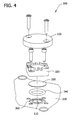
Figure 4 is a schematic illustration of the protective cap assembly shown inFigure 3 . - An electromechanical actuator system (EMA) includes a housing that maintains its aridity during a course of repeated flight cycles while reducing pressure differences that may be created between an internal pressure within the housing and an external pressure of the surrounding environment is desired. As described herein, maintaining the aridity of the housing facilitates increasing reliability of the actuator mechanism (actuator) encased within the housing, and reducing pressure differences facilitates reducing sealing requirements of the housing and increasing a useful seal life.
-
Figure 1 is a cross-sectional schematic illustration of an exemplary electromechanical actuator system, or EMA, 100 that may be used in an aircraft (not shown). In the exemplary embodiment, EMA 100 includes amoisture pump 110, aprotective cap 120, ahousing 130, anactuator 140, and acavity 150.Housing 130 includes amoisture pump 110, which is an opening oriented from an internal surface to an external surface ofhousing 130.Protective cap 120 is coupled tohousing 130 such that it substantially coversmoisture pump 110.Actuator 140 is positioned withincavity 150 defined by the internal surface ofhousing 130. - During a typical flight cycle of the aircraft, housing 130 experiences varying internal pressures and temperatures. For example, during the aircraft ascent, the internal pressure and temperature within
housing 130 decreases as the external pressure and temperature of the surrounding environment decrease until the aircraft is at cruising altitude. Conversely, during the aircraft descent, the internal pressure and temperature withinhousing 130 generally increases as the external pressure and temperature of the surrounding environment increases. - To balance the internal pressure and temperature within
housing 130 with the external pressure and temperature of the surrounding environment,moisture pump 110 facilitates venting of air into, and out of, housing 130. For example, during aircraft ascent,moisture pump 110 discharges air fromhousing 130 throughmoisture pump 110 as the external pressure and temperature of the surrounding environment decreases. During aircraft descent, air entershousing 130 throughmoisture pump 110 as the external pressure and temperature of the surrounding environment increases. - To protect
actuator 140 from water, moisture, and/or condensation,protective cap 120 provides interfacial sealing that inhibits water from enteringhousing 130 throughmoisture pump 110. More specifically,protective cap 120 facilitates protectingmoisture pump 110 andactuator 140 from incidental water ingress, water spray, surface water, and clogging. Moreover,protective cap 120 preventshousing 130 from ingesting more liquid throughmoisture pump 110 than can be expelled fromhousing 130 throughmoisture pump 110. In an alternative embodiment,protective cap 120 encaseshousing 130. In such an embodiment,protective cap 120 provides moisture ingress protection due to its relative geometry and orientation tomoisture pump 110. -
Figure 2 is a cross-sectional schematic illustration of EMA 100. In the exemplary embodiment,housing 130 includes a moisture trap 210 and/or a desiccant cartridge 220. Moisture trap 210 is a cavity that is defined betweenmoisture pump 110 andcavity 150. Desiccant cartridge 220 is a material positioned betweenmoisture pump 110 andcavity 150. - In the exemplary embodiment, moisture trap 210 is sized and oriented to trap incidental liquid water ingress in a location remote from
actuator 140. More specifically, water seeping throughmoisture pump 110 is retained in moisture trap 210 and is prevented from contactingactuator 140. Ultimately, any water residing in moisture trap 210 is expelled fromhousing 130 as air is channeled into and fromhousing 130 throughmoisture pump 110. - In the exemplary embodiment, desiccant cartridge 220 is fabricated from a material that enables it to absorb incidental liquid water ingress. More specifically, water seeping through
moisture pump 110 is absorbed by desiccant cartridge 220 and is prevented from contactingactuator 140. -
Figures 3 and4 are schematic illustrations of an exemplaryprotective cap assembly 300 that may be used with EMA 100 (shown inFigures 1 and2 ). In the exemplary embodiment,protective cap assembly 300 includesprotective cap 120, abase 320, aporous membrane 330, anelastomer ring 340, and adiffusion inhibition tube 350. Elastomerring 340 is also known as O-ring and is substantially circular. In alternative embodiments, eachfeature - In the exemplary embodiment,
protective cap assembly 300 is coupled tohousing 130 such that it substantially coversmoisture pump 110. More specifically,housing 130 is coupled tobase 320, such thatporous membrane 330 is retained againsthousing 130. Moreover,housing 130 includes agroove 360 that is sized and oriented to position O-ring 340 betweenhousing 130 andbase 320. More specifically, O-ring 340 is sized and shaped to fit securely in a mating relationship withingroove 360 formed underbase 320. - In the exemplary embodiment,
porous membrane 330 inhibits water from enteringhousing 130 throughmoisture pump 110 while still enabling water to leavehousing 130 throughmoisture pump 110 because of its composition.Porous membrane 330 can be fabricated from any material composition that facilitates this function. Some examples ofporous membrane 330 include, but are not limited to, a fabric water barrier such as Teflon (Teflon is a registered trademark of the DuPont Company for products made from fluoropolymers), a sintered metal water barrier, and a sintered ceramic water barrier. - In the exemplary embodiment, O-
ring 340 is fabricated from an elastomer and has a substantially circular cross-section shape. Moreover, O-ring 340 facilitates sealing betweenhousing 130 andbase 320. - In the exemplary embodiment,
diffusion inhibition tube 350 is a narrow tube that connectsmoisture pump 110 to cavity 150 (not shown inFigures 3 and4 ).Diffusion inhibition tube 350 slows water vapor ingress during steady state ground conditions. More specifically,diffusion inhibition tube 350 has a length that is sized relative to its diameter such that a length-to-diameter ratio ofdiffusion inhibition tube 350 facilitates reducing a rate of air exchange between the cavity ofhousing 130 and the surrounding environment. Thus,diffusion inhibition tube 350 facilitates reducing a rate of humidity exchange withinhousing 130. - Exemplary embodiments of a breather apparatus on electromechanical actuators for aircraft landing gear systems are described above in detail. The methods and systems are not limited to the specific embodiments described herein, but rather, components of systems and/or steps of the methods may be utilized independently and separately from other components and/or steps described herein. For example, the methods may also be used in combination with other systems and methods, and are not limited to practice with only the systems and methods as described herein. Rather, the exemplary embodiment can be implemented and utilized in connection with many other applications.
- Although specific features of various embodiments of the invention may be shown in some drawings and not in others, this is for convenience only. In accordance with the principles of the invention, any feature of a drawing may be referenced and/or claimed in combination with any feature of any other drawing.
- This written description uses examples to disclose the invention, including the best mode, and also to enable any person skilled in the art to practice the invention, including making and using any devices or systems and performing any incorporated methods. The patentable scope of the invention is defined by the claims, and may include other examples that occur to those skilled in the art. Such other examples are intended to be within the scope of the claims if they have structural elements that do not differ from the literal language of the claims, or if they include equivalent structural elements with insubstantial differences from the literal languages of the claims.
Claims (15)
- An actuator system (100) comprising:a housing (130) comprising a cavity (150) defined by said housing and an opening defined in a wall of said housing, said housing encasing an actuator within said cavity; anda cap (120) coupled to said housing to facilitate shielding said opening from a surrounding environment.
- An actuator system (100) in accordance with claim 1, wherein said cap (210) facilitates inhibiting moisture from entering said housing.
- An actuator system (100) in accordance with claim 1 or 2, further comprising a diffusion inhibition tube (350) that facilitates inhibiting moisture from entering said cavity (150).
- An actuator system (100) in accordance with any of the preceding claims, further comprising a moisture trap (210) that facilitates inhibiting fluids entering said housing (130) through said opening from contacting the actuator (140) encased within said housing.
- An actuator system (100) in accordance with any of the preceding claims, further comprising a porous membrane (330) that facilitates inhibiting fluids from entering said housing (130) through said opening.
- An actuator system (100) in accordance with any of the preceding claims, further comprising a porous membrane (330) that facilitates removing moisture from said housing (130).
- An actuator system (100) in accordance with any of the preceding claims, further comprising a porous membrane (330) fabricated from at least one of a fabric material, a sintered metal material, and a sintered ceramic material.
- An actuator system (100) in accordance with any of the preceding claims, further comprising a desiccant cartridge (220) that facilitates increasing an aridity within said cavity (150).
- An actuator system (100) in accordance with any of the preceding claims, wherein said cap (120) at least one of circumscribes said opening and encases said housing (130).
- An actuator system (100) in accordance with any of the preceding claims, wherein said cap (120) comprises a base (320), a porous membrane (330), and an elastomer ring (340).
- A method for assembling an actuator system, said method comprising:positioning a housing to encase an actuator within a cavity defined by the housing; andcoupling a cap to the housing to facilitate shielding an opening defined in a wall of the housing from a surrounding environment.
- A method in accordance with claim 11, wherein coupling a cap to the housing further comprises coupling the cap to the housing to facilitate inhibiting moisture from entering the housing.
- A method in accordance with claim 11 or 12, further comprising coupling a diffusion inhibition tube to the housing to facilitate inhibiting moisture from entering the cavity.
- A method in accordance with any of claims 11 to 13, further comprising coupling a moisture trap to the housing to facilitate inhibiting fluids entering the housing through the opening from contacting the actuator encased within the housing.
- A method in accordance with any of claims 11 to 14, further comprising coupling a porous membrane to the cap to facilitate inhibiting fluids from entering the housing through the opening.
Applications Claiming Priority (1)
| Application Number | Priority Date | Filing Date | Title |
|---|---|---|---|
| US12/240,536 US8328135B2 (en) | 2008-09-29 | 2008-09-29 | Breather apparatus on electromechanical actuators for aircraft landing gear systems |
Publications (2)
| Publication Number | Publication Date |
|---|---|
| EP2168870A2 true EP2168870A2 (en) | 2010-03-31 |
| EP2168870A3 EP2168870A3 (en) | 2015-12-02 |
Family
ID=41426249
Family Applications (1)
| Application Number | Title | Priority Date | Filing Date |
|---|---|---|---|
| EP09170537.6A Withdrawn EP2168870A3 (en) | 2008-09-29 | 2009-09-17 | Breather apparatus on electromechanical actuators for aircraft landing gear systems |
Country Status (6)
| Country | Link |
|---|---|
| US (2) | US8328135B2 (en) |
| EP (1) | EP2168870A3 (en) |
| JP (1) | JP5584856B2 (en) |
| CN (1) | CN101712376B (en) |
| BR (1) | BRPI0903552B1 (en) |
| CA (1) | CA2680635A1 (en) |
Families Citing this family (2)
| Publication number | Priority date | Publication date | Assignee | Title |
|---|---|---|---|---|
| JP2015133841A (en) * | 2014-01-14 | 2015-07-23 | 株式会社安川電機 | Motor and motor unit |
| US10639579B2 (en) | 2014-10-01 | 2020-05-05 | Donaldson Company, Inc. | Pleated tank vent |
Family Cites Families (27)
| Publication number | Priority date | Publication date | Assignee | Title |
|---|---|---|---|---|
| US22890A (en) * | 1859-02-08 | Carpet-sweeper | ||
| US1939845A (en) * | 1928-11-09 | 1933-12-19 | Westinghouse Air Brake Co | Brake cylinder protector |
| US2202207A (en) * | 1937-05-26 | 1940-05-28 | Lewis Eng Co | Electric switch |
| US2830671A (en) * | 1955-09-28 | 1958-04-15 | W L Maxson Corp | Desiccator |
| US2837926A (en) * | 1956-11-16 | 1958-06-10 | Haydon Switch Inc | Sealed drive mechanism |
| US4557177A (en) | 1983-04-26 | 1985-12-10 | C.T.M. Company, Inc. | Electromechanical actuator |
| JPH01149611U (en) * | 1988-04-06 | 1989-10-17 | ||
| US5209125A (en) * | 1989-12-22 | 1993-05-11 | The Foxboro Company | Piezoelectric pressure sensor |
| US5349894A (en) | 1993-10-01 | 1994-09-27 | Loud Engineering & Manufacturing | Locking hydraulic actuator |
| US5367417A (en) * | 1993-12-16 | 1994-11-22 | International Business Machines Corporation | Disk drive with flow-by chemical breather filter |
| JPH0861556A (en) * | 1994-08-12 | 1996-03-08 | Aichi Electric Co Ltd | Draining device of self-hold type solenoid |
| JPH09191597A (en) * | 1996-01-09 | 1997-07-22 | Matsushita Electric Ind Co Ltd | Motor casing device |
| JPH09261906A (en) * | 1996-03-21 | 1997-10-03 | Asmo Co Ltd | Waterproofing structure for motor |
| JPH10164872A (en) * | 1996-11-29 | 1998-06-19 | Canon Precision Inc | Vibration wave motor |
| JP4078697B2 (en) * | 1997-12-02 | 2008-04-23 | 株式会社デンソー | ABS actuator |
| US6058969A (en) * | 1998-12-29 | 2000-05-09 | Ford Global Technologies, Inc. | Vent system for an automatic transmission |
| JP3535765B2 (en) * | 1999-03-29 | 2004-06-07 | ダイワ精工株式会社 | Electric reel for fishing |
| US6266208B1 (en) * | 1999-06-11 | 2001-07-24 | Maxtor Corporation | Integrated filter for use in a disk drive |
| JP2000356601A (en) * | 1999-06-14 | 2000-12-26 | Meidensha Corp | Dew condensation preventive device in wave guide |
| US6515827B1 (en) * | 1999-07-08 | 2003-02-04 | Storage Technology Corporation | Dual chambered environmentally controlled cartridge and method for protecting data storage media |
| US6395073B1 (en) * | 1999-08-23 | 2002-05-28 | Gore Enterprise Holdings, Inc. | Multi-functional filter for removing contaminants from an enclosure |
| JP2002370636A (en) * | 2001-06-13 | 2002-12-24 | Unisia Jecs Corp | Hydraulic unit for vehicle brake system |
| US7098619B2 (en) | 2004-01-28 | 2006-08-29 | Stridsberg Innovation Ab | Actuator and movement linkage system |
| US7525404B2 (en) * | 2004-08-19 | 2009-04-28 | Remy Inc. | Moisture exhausting membrane in electrical solenoid |
| JP2006155973A (en) * | 2004-11-26 | 2006-06-15 | Nissan Motor Co Ltd | Hydrogen concentration detector for fuel cells |
| GB0618572D0 (en) * | 2006-09-21 | 2006-11-01 | Goodrich Actuation Systems Ltd | Actuator |
| US20080141803A1 (en) * | 2006-10-26 | 2008-06-19 | Honeywell International, Inc. | Electromechanical linear actuator including an environmental control and air management system |
-
2008
- 2008-09-29 US US12/240,536 patent/US8328135B2/en active Active
-
2009
- 2009-09-16 BR BRPI0903552-4A patent/BRPI0903552B1/en active IP Right Grant
- 2009-09-17 EP EP09170537.6A patent/EP2168870A3/en not_active Withdrawn
- 2009-09-24 CA CA 2680635 patent/CA2680635A1/en not_active Abandoned
- 2009-09-25 JP JP2009219866A patent/JP5584856B2/en active Active
- 2009-09-29 CN CN200910204712.4A patent/CN101712376B/en active Active
-
2012
- 2012-12-04 US US13/693,225 patent/US8590836B2/en active Active
Non-Patent Citations (1)
| Title |
|---|
| None * |
Also Published As
| Publication number | Publication date |
|---|---|
| CA2680635A1 (en) | 2010-03-29 |
| JP5584856B2 (en) | 2014-09-10 |
| JP2010083481A (en) | 2010-04-15 |
| CN101712376A (en) | 2010-05-26 |
| US8328135B2 (en) | 2012-12-11 |
| EP2168870A3 (en) | 2015-12-02 |
| BRPI0903552A2 (en) | 2010-06-01 |
| CN101712376B (en) | 2014-09-03 |
| BRPI0903552B1 (en) | 2019-06-25 |
| US8590836B2 (en) | 2013-11-26 |
| US20130118613A1 (en) | 2013-05-16 |
| US20100077744A1 (en) | 2010-04-01 |
Similar Documents
| Publication | Publication Date | Title |
|---|---|---|
| EP2964518B1 (en) | Aircraft drainage system | |
| US10017238B2 (en) | Drained fluid evacuation stub for a propulsion assembly | |
| JP5255901B2 (en) | Safety valve device | |
| US20140290383A1 (en) | Water resistant aircraft pitot device | |
| US8328135B2 (en) | Breather apparatus on electromechanical actuators for aircraft landing gear systems | |
| EP2897149B1 (en) | Pneumatic detector with integrated electrical contact | |
| US10247938B2 (en) | Passive reduction or elimination of frost and fog with expandable air container | |
| US20200324154A1 (en) | Fire-fighting system for an aircraft, having a double-chamber reservoir | |
| US11459955B2 (en) | Fire mitigation system for gas turbine engine | |
| US10077104B2 (en) | Proximity sensor for aircraft and having a hydraulic fuse | |
| US11466788B2 (en) | Pressure relief valve assembly | |
| US5578997A (en) | Fuel detector for a turbojet engine oil tank | |
| US7927402B1 (en) | Passive desiccant system | |
| US20200040982A1 (en) | Fluid supply over range of gravitational conditions | |
| CN101520063A (en) | Constant-pressure water evaporator suitable for aerospace craft | |
| US20200378861A1 (en) | Burst-duct detection system | |
| RU197364U1 (en) | Air intake device with resettable plug for an unmanned aerial vehicle with an air-jet engine | |
| CN220249036U (en) | Explosion-proof breather valve and equipment | |
| CN220884785U (en) | Aircraft brake hydraulic safety device with bypass valve | |
| KR102942045B1 (en) | Diagnostic Breeder Dryer | |
| CN118998382A (en) | Unidirectional liquid draining device and amphibious aircraft provided with unidirectional liquid draining device | |
| BR102019020963B1 (en) | HYDRAULIC ACTUATOR SYSTEM |
Legal Events
| Date | Code | Title | Description |
|---|---|---|---|
| PUAI | Public reference made under article 153(3) epc to a published international application that has entered the european phase |
Free format text: ORIGINAL CODE: 0009012 |
|
| AK | Designated contracting states |
Kind code of ref document: A2 Designated state(s): AT BE BG CH CY CZ DE DK EE ES FI FR GB GR HR HU IE IS IT LI LT LU LV MC MK MT NL NO PL PT RO SE SI SK SM TR |
|
| AX | Request for extension of the european patent |
Extension state: AL BA RS |
|
| RAP1 | Party data changed (applicant data changed or rights of an application transferred) |
Owner name: GE AVIATION SYSTEMS LLC |
|
| RAP1 | Party data changed (applicant data changed or rights of an application transferred) |
Owner name: WHIPPANY ACTUATION SYSTEMS, LLC |
|
| PUAL | Search report despatched |
Free format text: ORIGINAL CODE: 0009013 |
|
| AK | Designated contracting states |
Kind code of ref document: A3 Designated state(s): AT BE BG CH CY CZ DE DK EE ES FI FR GB GR HR HU IE IS IT LI LT LU LV MC MK MT NL NO PL PT RO SE SI SK SM TR |
|
| AX | Request for extension of the european patent |
Extension state: AL BA RS |
|
| RIC1 | Information provided on ipc code assigned before grant |
Ipc: B64C 25/24 20060101AFI20151028BHEP Ipc: F17D 1/00 20060101ALI20151028BHEP |
|
| 17P | Request for examination filed |
Effective date: 20160602 |
|
| RBV | Designated contracting states (corrected) |
Designated state(s): AT BE BG CH CY CZ DE DK EE ES FI FR GB GR HR HU IE IS IT LI LT LU LV MC MK MT NL NO PL PT RO SE SI SK SM TR |
|
| 17Q | First examination report despatched |
Effective date: 20171204 |
|
| GRAP | Despatch of communication of intention to grant a patent |
Free format text: ORIGINAL CODE: EPIDOSNIGR1 |
|
| INTG | Intention to grant announced |
Effective date: 20180801 |
|
| GRAS | Grant fee paid |
Free format text: ORIGINAL CODE: EPIDOSNIGR3 |
|
| STAA | Information on the status of an ep patent application or granted ep patent |
Free format text: STATUS: THE APPLICATION IS DEEMED TO BE WITHDRAWN |
|
| 18D | Application deemed to be withdrawn |
Effective date: 20181212 |