EP2167841B1 - Locking device - Google Patents
Locking device Download PDFInfo
- Publication number
- EP2167841B1 EP2167841B1 EP08766923.0A EP08766923A EP2167841B1 EP 2167841 B1 EP2167841 B1 EP 2167841B1 EP 08766923 A EP08766923 A EP 08766923A EP 2167841 B1 EP2167841 B1 EP 2167841B1
- Authority
- EP
- European Patent Office
- Prior art keywords
- clamps
- locking device
- chain
- clamp
- cable
- Prior art date
- Legal status (The legal status is an assumption and is not a legal conclusion. Google has not performed a legal analysis and makes no representation as to the accuracy of the status listed.)
- Not-in-force
Links
Images


Classifications
-
- F—MECHANICAL ENGINEERING; LIGHTING; HEATING; WEAPONS; BLASTING
- F16—ENGINEERING ELEMENTS AND UNITS; GENERAL MEASURES FOR PRODUCING AND MAINTAINING EFFECTIVE FUNCTIONING OF MACHINES OR INSTALLATIONS; THERMAL INSULATION IN GENERAL
- F16G—BELTS, CABLES, OR ROPES, PREDOMINANTLY USED FOR DRIVING PURPOSES; CHAINS; FITTINGS PREDOMINANTLY USED THEREFOR
- F16G15/00—Chain couplings, Shackles; Chain joints; Chain links; Chain bushes
-
- B—PERFORMING OPERATIONS; TRANSPORTING
- B63—SHIPS OR OTHER WATERBORNE VESSELS; RELATED EQUIPMENT
- B63B—SHIPS OR OTHER WATERBORNE VESSELS; EQUIPMENT FOR SHIPPING
- B63B21/00—Tying-up; Shifting, towing, or pushing equipment; Anchoring
- B63B21/18—Stoppers for anchor chains
-
- Y—GENERAL TAGGING OF NEW TECHNOLOGICAL DEVELOPMENTS; GENERAL TAGGING OF CROSS-SECTIONAL TECHNOLOGIES SPANNING OVER SEVERAL SECTIONS OF THE IPC; TECHNICAL SUBJECTS COVERED BY FORMER USPC CROSS-REFERENCE ART COLLECTIONS [XRACs] AND DIGESTS
- Y10—TECHNICAL SUBJECTS COVERED BY FORMER USPC
- Y10T—TECHNICAL SUBJECTS COVERED BY FORMER US CLASSIFICATION
- Y10T24/00—Buckles, buttons, clasps, etc.
- Y10T24/39—Cord and rope holders
- Y10T24/3902—Chain
Definitions
- the present invention relates to a method and device for temporarily securing or locking a chain or cable under tension during different operations. More specifically the present invention relates to an improved locking device, or a so-called “shark jaw", for a chain or a cable.
- US 6.446.568 relates to improvements to a locking device for locking and securing cables or chains.
- the device comprises a "fork" structure comprising two substantially parallel teeth defining an opening there between in which opening one link of a chain may rest, so that the next link rests against the teeth of the fork.
- the distance between the teeth has to correspond to the dimension of the chain.
- US 4.423.697 (corresponding to NO 146271 ) relates to a hydraulically operated locking device for a cable or chain, comprising a jaw means having a pair of locking jaws that are moved towards/from one another by rotation of the jaw means about horizontal and parallel axis to close / open the locking device.
- the jaw means are rotated between the closed and open position by extracting/withdrawing a piston rod from/into a jack cylinder, allowing the locking device to be remotely operated.
- the locking means is, however, designed for one dimension of chain / wire.
- NO 180776 relates to an alternative locking device for a wire or chain onboard a vessel, the locking device comprising two claw means that maybe rotated about vertical axis of rotation between an open and a locked position.
- the locking means are also integrated with two guide rods.
- notches are provided in the claws to give an aperture between the claw means adapted to allow one dimension of wire or chain to be locked without being damaged.
- US 6.446.568 is illustrative for the predominant locking devices for anchor handling vessels.
- an insert optionally substituting an existing insert, has to be installed on the locking device.
- the substitution and mounting of the inserts is manual work requiring crew at the aft deck. Of security reasons, it is however, a goal to avoid crew at the aft deck during anchor handling operation. In heavy weather, it may even be impossible to send personnel to the aft deck to exchange the inserts, a situation that may result in an expensive stop in a planned or otherwise necessary operation.
- One object of the present invention is therefore to provide locking means for a chain and/or a cable, that makes it possible to reduce or even avoid the necessity of having personnel at the aft deck of a vessel during lifting operations, such as anchor handling operations.
- Another object is to provide a locking means that reduces or avoids stops in planned or otherwise necessary operations, by providing a locking device that may be remotely controlled.
- a locking device for temporary locking and securing of a chain, cable or wire, suitable to be arranged at the aft deck of a supply vessel or a anchor handling vessel, having the features of claim 1.
- the clamps are arranged in a track in the main body of the locking device.
- the main body and the teeth of the main body may give the required support and strength to the device.
- the track may be defined by a recess in the main body, a cover covering the recess, and a support member.
- the locking device does according to one embodiment, include a substantially vertically displaceable clamp frame that is arranged in the groove and covered by the cover, the clamp frame comprising one or more slanting surface(s) that is/are arranged to interact on correspondingly slanting surface(s) on the clamps to displace the clamps substantially horizontally when the clamp frame is moved vertically.
- guide pins fastened to the clamp frame are arranged in corresponding slanting guide tracks arranged in the clamps.
- guide pins fastened to the clamp are arranged in corresponding slanting guide tracks arranged in the clamps frame.
- the clamp frame comprises two clamp frame parts, each supporting one clamp. Tests done by the applicant has shown that operation of the device is improved and the reliability improved if the clamp frame is divided in two, preferably independent, clamp frame parts each supporting one clamp.
- the clamp frame parts may be operated by separate actuators. When the clamp frame parts are operated by separate actuators, the control and fail safe properties of the device is further improved.
- the top part of the teeth are preferably slanting towards the gap to guide a chain, wire or cable towards the gap.
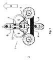
- Figure 1 is a bird eye's view of a first embodiment of the present locking device, or "shark jaw" 1, arranged at an aft deck 2 of a vessel together with a pair of tow line guide pins 3 provided with cross members 4.
- the orientation of the shark jaw and tow pins is indicated by an arrow B pointing in the length direction towards the bow of the vessel.
- a chain 8 is arranged in the shark jaw and between the tow pins 3 to illustrate the position of the chain 8 in active use of the shark jaw and tow pins.
- the tow line guide pins 3 and cross members 4 are of a well known type that may be lowered into the deck of the vessel, and where the tow pins 3 or a top part thereof, may be rotated to move the cross members from a first position as illustrated in the figure, to an open position where the cross members are running substantially parallel to the chain 8 to allow the chain to be lifted out over the tow pins. Even thought the tow pins and shark jaw are illustrated in their active position in figure 1 , the tow pins and shark jaw may be used independently of each other.
- the shark jaw comprises a fork shaped main body 5 having two teeth 6 defining an opening 10 between them.
- the distance between the two teeth 6, or the opening 10, is wider than the diameter of the maximum chain diameter (diameter of each chain link) to be used with the shark jaw.
- Adjustable clamps 7 are arranged on the teeth 6 as described in detail below, to allow for adjusting the distance between the claims according to the dimension of the chain 8.
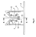
- FIG 2 illustrates a shark jaw 1 in its active, or upper, position seen from the deck towards the stem of the vessel.
- a cover 11 covers a recess at the front part of the main body 5 and parts of the teeth 6 of the shark jaw .
- the cover 11 is fastened to the main body by means of bolts 12, 13, 14.
- Figure 3 illustrates the shark jaw seen from abaft.
- Figure 4 is a illustrates the section A-A of figure 2 , and shows the adjustable clams 7 arranged in a recess in the main body 5 and teeth 6 supported by the cover 11 and resting on a support member 15 at the lower end of the adjustable clamp.
- the recess, cover and base member define a track for the movement of the clamps 7, to make a track in which the clamps are displaceable arranged.
- the adjustable inserts 7 are allowed to be displaced horizontally substantially perpendicular to the length axis of the vessel to adjust the gap between the inserts 7.
- a clamp frame 16 is also arranged in the recess in the main body, covered by the cover 11.
- the clamp frame is adapted to be moved substantially vertically by means of not shown actuators, in the recess in the main body 5 and teeth 6.
- the clamp frame 16 is operateably connected to the adjustable clamps in that slanting surfaces 20 of the clamp frame rests against correspondingly slanting surfaces 20' of the adjustable clamps. In the devices illustrated in figures 5 and 7 , and upwards movement of the clamp frame 16 will cause the adjustable clamps 7 to be moved against each other to reduce the distance between the clamps 7.
- the adjustable clamps 7 are moved away from each other by means of guide pins 18, 18' connected to the clamp frame 16 and are inserted into guide tracks 19, 19' in the adjustable clamps, resulting in the adjustable clamps being removed from each other, due to the guide tracks being inclined relative to a horizontal line.
- the guide track are inclined at the same angle as the slanting surface 20.
- the embodiment according to figure 5 has two slanting surfaces 20, 20' for each of the two adjustable clamps, whereas only one slanting surface for each of the adjustable clamps are present in the embodiment of figure 7 .
- Guide rods 22 that are arranged in vertical guide tracks 21, may also be provided to guide the clamp frame. Additionally, cutouts 17, 17' is preferably provided for the bolts 13, 13'.
- the adjustable clamps are remotely adjusted according to the diameter of the wire, cable or chain to allow them to be inserted between the adjustable clamps without being squeezed between the clamps.
- a wire clam or wire lock arranged on the wire or cable will be stopped by the adjustable clams and thus be locked to the shark jaw.
- the shark jaw or a chain the next chain link will be caused to rest against the adjustable clams if the shark jaw is correctly adjusted, to lock the chain to the shark jaw.
- the teeth 6 are preferably inclined towards the opening 10 to provide a self centring effect to lead a chain, cable or wire that is placed between the teeth towards the opening 10 and into engagement with the inserts.
- a support part 9 of the main body is provided aft of the opening 10 as a support for the first chain link aft of the opening 10.
- the present shark jaw is remotely adjustable so that the shark jaw may be used for several dimensions of chain, cable or wire.
- the distance between the inserts corresponds to the diameter of the chain, so that a vertically arranged chain link fits in between the inserts. A chain that is too large will not fit into the locking opening, resulting in no or inadequate locking. If the distance between the inserts is too wide, the result may again be poor or inadequate locking and even damages on the chain.
- Both the shark jaw 1 and the tow line guide pins 3 are preferably vertically displaceable so that they may be moved from stowed position where the top of the shark jaw and/or the tow pins are at the level with or below the deck 2, and to an active position where the active parts of the shark jaw and tow pins are above deck.
- cover(s) that may be handled manually or automatically, may be present to cover the shark jaw and / or the tow pins when they are in the lower or sowed position.
- the shark jaw and tow pins are arranged in recesses in the deck supported by not illustrated structures below deck and connected to actuators and controls for the operation of the shark jaw and tow pins as described below.
- the shark jaw and the guide pins may be lowered into and ejected from the deck 2 independently of each other.
- the guide pins in this embodiment are conventional guide pins, e.g. as known from US 4.503.649 , which is included in the present description as reference.
- Locking members 4 arranged at top of the guide pins may be rotated about the vertical axis of the guide pins from an open position where the locking members are parallel to each other and are substantially parallel with the length axis of the vessel, and a locked position where the locking members faces each other and prevents a chain, a line of wire positioned between the guide pins to be drawn up above the guide pins.
- the main body 5 of the shark jaw is according to one embodiment, connected to a substantially tubular base member 23 that is vertically displaceable between a position where the shark jaw is below deck, and a position where the top of the base member is substantially flush with the deck.
- the base member is arranged in a supporting structure to give the shark jaw the necessary support and strength.
- Figure 7 is a view A-A also including the base member 23, of an alternative embodiment, where the clamp frame 16 is split into two parts 16', 16", one part 16', 16" supporting one of the clamps 7. Each part is here controlled by an individual actuator 25.
- the actuators both in this embodiment and the other embodiments of the invention, may be hydraulic actuators or electrical actuators as illustrated in figure 7 .
- the electrical actuators 25 illustrated in figure 7 is connected to a treaded bar 26 having a treaded connection to either the actuator 25 or a treaded member of the clamp frame part 16', 16" so that a rotation in the actuators is converted into a vertical movement of the clamp frame part 16', 16".
- Figure 8 illustrates an alternative embodiment in views corresponding to the view of figure 2 , where only one slanting surface is present per clamp.
- the figure to the left illustrates the shark jaw having wide gap 10, whereas the view to the right illustrates a more narrow gap 10.
- the figure clearly illustrates that the upper position of the clamp frame corresponds to a narrow gap 10 and the lower position to a wide gap.
- Figure 9 is a bird's eye view of a shark jaw 5 according to the present invention combined with tow pins.
- the locking members 4 of the tow pins 3, are closed.
- the tow pins may be lowered into the deck into recesses 24 when not in use.
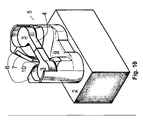
- Figure 10 is a perspective view of an embodiment of the present shark jaw where the tow pins 3 and shark jaw is combined into an integrated unit.
Landscapes
- Engineering & Computer Science (AREA)
- General Engineering & Computer Science (AREA)
- Mechanical Engineering (AREA)
- Chemical & Material Sciences (AREA)
- Combustion & Propulsion (AREA)
- Ocean & Marine Engineering (AREA)
- Clamps And Clips (AREA)
- Power-Operated Mechanisms For Wings (AREA)
- Catching Or Destruction (AREA)
Description
- The present invention relates to a method and device for temporarily securing or locking a chain or cable under tension during different operations. More specifically the present invention relates to an improved locking device, or a so-called "shark jaw", for a chain or a cable.
- During several operations at the aft deck of a supply vessel or more specifically an anchor handling vessel, it is necessary to temporarily secure or lock a cable or chain under tension to perform operations such as, without limitations, shackling, connecting one chain with another, and substitution of parts of a cable or chain with another. Cable locks or chain locks of different kinds are routinely used for this purpose.
-
US 6.446.568 relates to improvements to a locking device for locking and securing cables or chains. The device comprises a "fork" structure comprising two substantially parallel teeth defining an opening there between in which opening one link of a chain may rest, so that the next link rests against the teeth of the fork. To give an effective locking without damaging the locking device and/or the chain, the distance between the teeth has to correspond to the dimension of the chain. - The main drawback with a locking device according to
US 6.446.567 is that the opening defined between the teeth of the fork is constant, corresponding to the largest chain that may be used for that locking device. To adjust the device for a chain having smaller dimensions, inserts has to be installed. The inserts have to be manually mounted and secured by means of bolts, an operation which requires the presence of crew at the aft deck of the vessel. -
US 4.423.697 (corresponding toNO 146271 -
NO 180776 - During an offshore lifting operation, such as an anchor handling operation, the information about the dimension of chains and/or wires connected to equipment to be handled, is not always accurate. To handle such situations, the locking means have to be adjustable. Accordingly, the devices according to
US .423.697 andNO 180776 -
US 6.446.568 is illustrative for the predominant locking devices for anchor handling vessels. As mentioned above, to adjust the locking device according toUS 6.446.568 , an insert, optionally substituting an existing insert, has to be installed on the locking device. The substitution and mounting of the inserts is manual work requiring crew at the aft deck. Of security reasons, it is however, a goal to avoid crew at the aft deck during anchor handling operation. In heavy weather, it may even be impossible to send personnel to the aft deck to exchange the inserts, a situation that may result in an expensive stop in a planned or otherwise necessary operation. - One object of the present invention is therefore to provide locking means for a chain and/or a cable, that makes it possible to reduce or even avoid the necessity of having personnel at the aft deck of a vessel during lifting operations, such as anchor handling operations.
- Another object is to provide a locking means that reduces or avoids stops in planned or otherwise necessary operations, by providing a locking device that may be remotely controlled.
- The above mentioned and other objects have been met by means of a locking device for temporary locking and securing of a chain, cable or wire, suitable to be arranged at the aft deck of a supply vessel or a anchor handling vessel, having the features of claim 1.
- According to one embodiment, the clamps are arranged in a track in the main body of the locking device. By arranging the clamps in the main body of the locking device, the main body and the teeth of the main body may give the required support and strength to the device.
- The track may be defined by a recess in the main body, a cover covering the recess, and a support member.
- The locking device does according to one embodiment, include a substantially vertically displaceable clamp frame that is arranged in the groove and covered by the cover, the clamp frame comprising one or more slanting surface(s) that is/are arranged to interact on correspondingly slanting surface(s) on the clamps to displace the clamps substantially horizontally when the clamp frame is moved vertically.
- According to one embodiment, guide pins fastened to the clamp frame, are arranged in corresponding slanting guide tracks arranged in the clamps.
- According to another embodiment, guide pins fastened to the clamp, are arranged in corresponding slanting guide tracks arranged in the clamps frame.
- According to yet another embodiment, the clamp frame comprises two clamp frame parts, each supporting one clamp. Tests done by the applicant has shown that operation of the device is improved and the reliability improved if the clamp frame is divided in two, preferably independent, clamp frame parts each supporting one clamp.
- The clamp frame parts may be operated by separate actuators. When the clamp frame parts are operated by separate actuators, the control and fail safe properties of the device is further improved.
- The top part of the teeth are preferably slanting towards the gap to guide a chain, wire or cable towards the gap.
- The present invention will now be further explained by use of the enclosed figures, where
-
Fig. 1 is a bird's eye view of a shark jaw and to pins, -
Fig. 2 is a view of a shark jaw seen from the aft deck of a vessel towards aft of the vessel, -
Fig. 3 is view of a shark jaw seen from abaft, -
Fig. 4 is a cross section along A-A offigure 2 , -
Fig. 5 is a view corresponding tofig. 2 , where a cover is removed, -
Fig. 6 is a view corresponding tofig. 2 , where a cover and clamp frame are removed, -
Fig. 7 are sections corresponding tofigure 2 of a first alternative embodiment, -
Fig. 8 are sections corresponding tofigure 2 of a second alternative embodiment, -
Fig. 9 is a bird's eye view of an alternative embodiment of the shark jaw and tow pins, and -
Fig. 10 is a perspective view of an alternative embodiment having tow pins integrated with the shark jaw. -
Figure 1 is a bird eye's view of a first embodiment of the present locking device, or "shark jaw" 1, arranged at anaft deck 2 of a vessel together with a pair of towline guide pins 3 provided withcross members 4. - The orientation of the shark jaw and tow pins is indicated by an arrow B pointing in the length direction towards the bow of the vessel. A chain 8 is arranged in the shark jaw and between the
tow pins 3 to illustrate the position of the chain 8 in active use of the shark jaw and tow pins. The towline guide pins 3 andcross members 4 are of a well known type that may be lowered into the deck of the vessel, and where thetow pins 3 or a top part thereof, may be rotated to move the cross members from a first position as illustrated in the figure, to an open position where the cross members are running substantially parallel to the chain 8 to allow the chain to be lifted out over the tow pins. Even thought the tow pins and shark jaw are illustrated in their active position infigure 1 , the tow pins and shark jaw may be used independently of each other. - The shark jaw comprises a fork shaped
main body 5 having twoteeth 6 defining anopening 10 between them. The distance between the twoteeth 6, or theopening 10, is wider than the diameter of the maximum chain diameter (diameter of each chain link) to be used with the shark jaw.Adjustable clamps 7 are arranged on theteeth 6 as described in detail below, to allow for adjusting the distance between the claims according to the dimension of the chain 8. -
Figure 2 illustrates a shark jaw 1 in its active, or upper, position seen from the deck towards the stem of the vessel. Acover 11 covers a recess at the front part of themain body 5 and parts of theteeth 6 of the shark jaw . Thecover 11 is fastened to the main body by means ofbolts Figure 3 illustrates the shark jaw seen from abaft. -
Figure 4 is a illustrates the section A-A offigure 2 , and shows theadjustable clams 7 arranged in a recess in themain body 5 andteeth 6 supported by thecover 11 and resting on asupport member 15 at the lower end of the adjustable clamp. The recess, cover and base member define a track for the movement of theclamps 7, to make a track in which the clamps are displaceable arranged. Theadjustable inserts 7 are allowed to be displaced horizontally substantially perpendicular to the length axis of the vessel to adjust the gap between theinserts 7. - A
clamp frame 16 is also arranged in the recess in the main body, covered by thecover 11. The clamp frame is adapted to be moved substantially vertically by means of not shown actuators, in the recess in themain body 5 andteeth 6. - The
clamp frame 16 is operateably connected to the adjustable clamps in that slanting surfaces 20 of the clamp frame rests against correspondingly slanting surfaces 20' of the adjustable clamps. In the devices illustrated infigures 5 and7 , and upwards movement of theclamp frame 16 will cause theadjustable clamps 7 to be moved against each other to reduce the distance between theclamps 7. When the clamp frame is lowered, theadjustable clamps 7 are moved away from each other by means of guide pins 18, 18' connected to theclamp frame 16 and are inserted into guide tracks 19, 19' in the adjustable clamps, resulting in the adjustable clamps being removed from each other, due to the guide tracks being inclined relative to a horizontal line. Preferably, the guide track are inclined at the same angle as the slantingsurface 20. - The embodiment according to
figure 5 has two slantingsurfaces 20, 20' for each of the two adjustable clamps, whereas only one slanting surface for each of the adjustable clamps are present in the embodiment offigure 7 . -
Guide rods 22 that are arranged in vertical guide tracks 21, may also be provided to guide the clamp frame. Additionally,cutouts 17, 17' is preferably provided for thebolts 13, 13'. - In an offshore operation were the shark jaw is to be used for locking a wire, cable or chain, the adjustable clamps are remotely adjusted according to the diameter of the wire, cable or chain to allow them to be inserted between the adjustable clamps without being squeezed between the clamps. When used for a wire or a cable, a wire clam or wire lock arranged on the wire or cable will be stopped by the adjustable clams and thus be locked to the shark jaw. When using the shark jaw or a chain, the next chain link will be caused to rest against the adjustable clams if the shark jaw is correctly adjusted, to lock the chain to the shark jaw.
- The
teeth 6 are preferably inclined towards the opening 10 to provide a self centring effect to lead a chain, cable or wire that is placed between the teeth towards theopening 10 and into engagement with the inserts. - At the high tension side of the shark jaw, normally towards the aft end of the vessel, a
support part 9 of the main body is provided aft of theopening 10 as a support for the first chain link aft of theopening 10. - The present shark jaw is remotely adjustable so that the shark jaw may be used for several dimensions of chain, cable or wire. Preferably, the distance between the inserts corresponds to the diameter of the chain, so that a vertically arranged chain link fits in between the inserts. A chain that is too large will not fit into the locking opening, resulting in no or inadequate locking. If the distance between the inserts is too wide, the result may again be poor or inadequate locking and even damages on the chain.
- Both the shark jaw 1 and the tow line guide pins 3 are preferably vertically displaceable so that they may be moved from stowed position where the top of the shark jaw and/or the tow pins are at the level with or below the
deck 2, and to an active position where the active parts of the shark jaw and tow pins are above deck. Not shown cover(s) that may be handled manually or automatically, may be present to cover the shark jaw and / or the tow pins when they are in the lower or sowed position. The shark jaw and tow pins are arranged in recesses in the deck supported by not illustrated structures below deck and connected to actuators and controls for the operation of the shark jaw and tow pins as described below. It is preferred that the shark jaw and the guide pins may be lowered into and ejected from thedeck 2 independently of each other. The guide pins in this embodiment are conventional guide pins, e.g. as known fromUS 4.503.649 , which is included in the present description as reference. Lockingmembers 4 arranged at top of the guide pins may be rotated about the vertical axis of the guide pins from an open position where the locking members are parallel to each other and are substantially parallel with the length axis of the vessel, and a locked position where the locking members faces each other and prevents a chain, a line of wire positioned between the guide pins to be drawn up above the guide pins. - The
main body 5 of the shark jaw is according to one embodiment, connected to a substantiallytubular base member 23 that is vertically displaceable between a position where the shark jaw is below deck, and a position where the top of the base member is substantially flush with the deck. The base member is arranged in a supporting structure to give the shark jaw the necessary support and strength. -
Figure 7 is a view A-A also including thebase member 23, of an alternative embodiment, where theclamp frame 16 is split into twoparts 16', 16", onepart 16', 16" supporting one of theclamps 7. Each part is here controlled by anindividual actuator 25. The actuators, both in this embodiment and the other embodiments of the invention, may be hydraulic actuators or electrical actuators as illustrated infigure 7 . Theelectrical actuators 25 illustrated infigure 7 is connected to atreaded bar 26 having a treaded connection to either theactuator 25 or a treaded member of theclamp frame part 16', 16" so that a rotation in the actuators is converted into a vertical movement of theclamp frame part 16', 16". -
Figure 8 illustrates an alternative embodiment in views corresponding to the view offigure 2 , where only one slanting surface is present per clamp. The figure to the left illustrates the shark jaw havingwide gap 10, whereas the view to the right illustrates a morenarrow gap 10. The figure clearly illustrates that the upper position of the clamp frame corresponds to anarrow gap 10 and the lower position to a wide gap. -
Figure 9 is a bird's eye view of ashark jaw 5 according to the present invention combined with tow pins. The lockingmembers 4 of the tow pins 3, are closed. The tow pins may be lowered into the deck intorecesses 24 when not in use. -
Figure 10 is a perspective view of an embodiment of the present shark jaw where the tow pins 3 and shark jaw is combined into an integrated unit.
Claims (9)
- A locking device for temporary locking and securing of a chain, cable or wire clamp or lock, suitable to be arranged at the aft deck of a supply vessel or a anchor handling vessel, the device comprising a fork shaped main body (5) comprising two teeth (6) where clamps (7) extending from the teeth (6) towards each other, the clamps, in use, having substantially vertically arranged edges (7') facing each other and defining substantially vertical a gap (10) between the edges (7'), where the distance between the clamps being adapted to the diameter of a chain link or cable or a wire so that it may pass into the gap without being squeezed between the clamps, but where a next chain link of a chain or a clamp or lock on a cable or wire, is stopped against the clamps (7) to lock or secure the chain, cable or wire, characterised in that the locking clamps (7) are in use substantially linearly and horizontally displaceable, and substantially perpendicular to the length axis of the vessel for adjustment of the gap (10) between the clamps (7) according to the diameter of the cable or wire clamp or lock or chain link.
- The locking device according to claim 1, wherein the clamps (7) are arranged in a track in the main body (5) of the locking device.
- The locking device according to claim 2, wherein the track is defined by a recess in the main body (5), a cover (11) covering the recess, and a support member (15).
- The locking device according any of the preceding claims, wherein a substantially vertically displaceable clamp frame (16) is arranged in the groove and covered by the cover (11), the clamp frame (16) comprising one or more slanting surface(s) (20) that is/are arranged to interact on correspondingly slanting surface(s) (20') on the clamps (7) to displace the clamps (7) substantially horizontally when the clamp frame (16) is moved vertically.
- The locking device according to claim 4, wherein guide pins (18, 18') fastened to the clamp frame (16) are arranged in corresponding slanting guide tracks (19, 19') arranged in the clamps (7).
- The locking device according to claim 4, wherein guide pins (18, 18') fastened to the clamp (7) are arranged in corresponding slanting guide tracks (19, 19') arranged in the clamps frame (16).
- The locking device according to any of the preceding claims, wherein the clamp frame (16) comprises two clamp frame parts (16', 16"), each supporting one clamp (7).
- The locking device according to claim 7, wherein the clamp frame parts (16', 16") are operated by separate actuators (25).
- The locking device according to any of the preceding claims, wherein the top part of the teeth (6) are slanting towards the gap (10) to guide a chain, wire or cable towards the gap (10).
Applications Claiming Priority (2)
| Application Number | Priority Date | Filing Date | Title |
|---|---|---|---|
| NO20073010 | 2007-06-12 | ||
| PCT/NO2008/000210 WO2008153411A1 (en) | 2007-06-12 | 2008-06-12 | Locking device |
Publications (2)
| Publication Number | Publication Date |
|---|---|
| EP2167841A1 EP2167841A1 (en) | 2010-03-31 |
| EP2167841B1 true EP2167841B1 (en) | 2014-01-15 |
Family
ID=39816788
Family Applications (1)
| Application Number | Title | Priority Date | Filing Date |
|---|---|---|---|
| EP08766923.0A Not-in-force EP2167841B1 (en) | 2007-06-12 | 2008-06-12 | Locking device |
Country Status (6)
| Country | Link |
|---|---|
| US (1) | US20100154176A1 (en) |
| EP (1) | EP2167841B1 (en) |
| CN (1) | CN101711317B (en) |
| BR (1) | BRPI0812525B1 (en) |
| RU (1) | RU2469902C2 (en) |
| WO (1) | WO2008153411A1 (en) |
Families Citing this family (12)
| Publication number | Priority date | Publication date | Assignee | Title |
|---|---|---|---|---|
| NO330246B1 (en) | 2009-02-25 | 2011-03-14 | Odim Asa | Method and device for handling ropes |
| CN102451958A (en) * | 2010-10-21 | 2012-05-16 | 天津迎新船舶机械有限公司 | Small pipe fitting welding process of shark jaw device |
| SG11201406861VA (en) * | 2012-04-25 | 2014-11-27 | Delmar Systems Inc | In-line mechanical disconnect device |
| NO334333B1 (en) | 2012-05-04 | 2014-02-10 | Nat Oilwell Varco Norway As | Device for towing control and method for using the same |
| CN103224006B (en) * | 2013-04-27 | 2015-10-21 | 武汉船用机械有限责任公司 | A kind of shark pincer device |
| CN103231775B (en) * | 2013-04-27 | 2015-09-02 | 武汉船用机械有限责任公司 | A kind of V shape shark jaw |
| CN103538700B (en) * | 2013-10-30 | 2015-09-23 | 长江重庆航道局 | A kind of deep water navigation mark bidding bitt stopper and cast method |
| CN103803022B (en) * | 2014-03-18 | 2016-05-11 | 长江重庆航道局 | A kind of hawser apparatus |
| CN104802934B (en) * | 2015-04-01 | 2017-01-04 | 中国海洋石油总公司 | Anchor chain stops chain structure |
| FR3049925B1 (en) * | 2016-04-11 | 2018-05-04 | Dcns | GUIDE BOILER FOR AN ANCHORING ELEMENT OF AN OFFSHORE STRUCTURE |
| EP4114722A1 (en) * | 2020-03-06 | 2023-01-11 | Svitzer A/S | Line handling device and vessel comprising the line handling device |
| NO348614B1 (en) * | 2023-02-15 | 2025-03-31 | Kongsberg Maritime As | A tow pin device and a tow pin and shark jaw arrangement |
Family Cites Families (20)
| Publication number | Priority date | Publication date | Assignee | Title |
|---|---|---|---|---|
| US1728125A (en) * | 1929-09-10 | Clamp | ||
| FR343409A (en) | 1904-03-02 | 1904-10-06 | Richard Kuehnle | Device for retaining a stretching wire, particularly applicable to electrical conductors |
| US1478950A (en) * | 1923-03-24 | 1923-12-25 | Gilliam Eugene Carl | Wire-line clamp |
| US1504087A (en) * | 1924-01-05 | 1924-08-05 | Brady Judson Roy | Wire-line clamp |
| US1733010A (en) * | 1928-09-21 | 1929-10-22 | Green Ellis | Tubing spider |
| GB399305A (en) | 1932-08-24 | 1933-10-05 | George William Gentle | An improved clamp or fastening for ropes, cords, or similar bodies |
| US2071637A (en) * | 1935-06-17 | 1937-02-23 | W K M Company | Slip |
| US2066094A (en) * | 1935-08-17 | 1936-12-29 | James P Lloyd | Catline clamp |
| DE1573954B1 (en) * | 1966-12-06 | 1970-04-23 | Wafios Maschinen Wagner | Device for stretching and testing chain links |
| US3547066A (en) * | 1969-02-06 | 1970-12-15 | Boris Andreevich Bugaenko | Anchor chain arrester |
| US3758922A (en) | 1971-10-29 | 1973-09-18 | Sand R Ass Inc | Sliding wedge cleat |
| US3967572A (en) * | 1974-08-13 | 1976-07-06 | Santa Fe International Corporation | Anchoring system and chain stopper therefor |
| FR2346588A1 (en) * | 1975-10-20 | 1977-10-28 | Pradon Jacques | PLIERS OF TIGHTENING |
| SU785105A1 (en) * | 1978-12-11 | 1980-12-07 | Ленинградский Институт Водного Транспорта | Gripping device |
| NO146271C (en) * | 1980-06-12 | 1982-09-01 | Ulstein Trading | DEVICE FOR CHAIN LOCKING, WIRE, LINE OR LIKE A STATION CONSTRUCTION, SPECIAL BOAT TIRE |
| CA2095986C (en) * | 1993-05-11 | 1996-02-13 | Emeric Walter Johnson | Cable clamp |
| US5531297A (en) * | 1995-02-17 | 1996-07-02 | Harris-Johnson Industries, Inc. | Rope locking device |
| NO300675B1 (en) * | 1995-07-12 | 1997-07-07 | Karmoy Winch As | Stop and hold device for chain or wire |
| US6446568B1 (en) * | 1999-12-22 | 2002-09-10 | Karmoy Winch A/S | Stopping and retaining device for chain or wire |
| US6446567B2 (en) | 2000-02-08 | 2002-09-10 | Lora L. Hindsley | Portable hand-operated machine quilting clamp |
-
2008
- 2008-06-12 US US12/663,894 patent/US20100154176A1/en not_active Abandoned
- 2008-06-12 RU RU2009148138/11A patent/RU2469902C2/en active
- 2008-06-12 CN CN200880020217.1A patent/CN101711317B/en not_active Expired - Fee Related
- 2008-06-12 BR BRPI0812525-2A patent/BRPI0812525B1/en not_active IP Right Cessation
- 2008-06-12 EP EP08766923.0A patent/EP2167841B1/en not_active Not-in-force
- 2008-06-12 WO PCT/NO2008/000210 patent/WO2008153411A1/en not_active Ceased
Also Published As
| Publication number | Publication date |
|---|---|
| BRPI0812525A2 (en) | 2015-09-22 |
| CN101711317B (en) | 2015-05-06 |
| WO2008153411A1 (en) | 2008-12-18 |
| BRPI0812525B1 (en) | 2019-04-24 |
| EP2167841A1 (en) | 2010-03-31 |
| RU2009148138A (en) | 2011-07-20 |
| RU2469902C2 (en) | 2012-12-20 |
| US20100154176A1 (en) | 2010-06-24 |
| CN101711317A (en) | 2010-05-19 |
Similar Documents
| Publication | Publication Date | Title |
|---|---|---|
| US20100154176A1 (en) | Locking device | |
| US9381977B2 (en) | In-line mooring connector and tensioner | |
| CN101242989B (en) | System to guide a wire, chain, cable etc, onboard a vessel | |
| US9835268B2 (en) | Marine pipeline installation system and method | |
| FI64097B (en) | RELEASE FACTORY LIGHTING UPP EN PAO HAVSBOTTEN LIGGANDE ROERLEDNING MED TILLHJAELP AV ETT ROERNEDLAEGGNINGSFARTYG | |
| US8720059B2 (en) | Apparatus and method for aircraft engine core exchange | |
| EP2722571B1 (en) | Pipeline termination skid | |
| US8079627B2 (en) | Device for vertically holding pipes | |
| EP4007850B1 (en) | Clamp for wind turbine rotor blade | |
| US6554541B1 (en) | Method and device adapted for use in the placing of a suction anchor with an attached anchor chain or similar on the ocean bed | |
| WO2007117150A1 (en) | Device and method for a winch for pulling a riser up to a fixed or floating offshore installation | |
| EP3046832B1 (en) | Deflector grip adapter, deflector and system for launching and hauling of such a deflector | |
| US5249891A (en) | Guideline system for underwater observation camera systems | |
| WO2020005073A1 (en) | Locking mechanism for a rope on a vessel | |
| WO2021118366A1 (en) | A barrier device for assembly onto an eye-bolt and a method of assembling said barrier device | |
| US9951886B2 (en) | Arrangement system and method for retrieving a laydown head | |
| CN121734578A (en) | Deepwater FPSO multipoint mooring tensioning system | |
| WO2019009731A1 (en) | Apparatus and method for cutting a line extending from a floating vessel |
Legal Events
| Date | Code | Title | Description |
|---|---|---|---|
| PUAI | Public reference made under article 153(3) epc to a published international application that has entered the european phase |
Free format text: ORIGINAL CODE: 0009012 |
|
| 17P | Request for examination filed |
Effective date: 20100112 |
|
| AK | Designated contracting states |
Kind code of ref document: A1 Designated state(s): AT BE BG CH CY CZ DE DK EE ES FI FR GB GR HR HU IE IS IT LI LT LU LV MC MT NL NO PL PT RO SE SI SK TR |
|
| AX | Request for extension of the european patent |
Extension state: AL BA MK RS |
|
| 17Q | First examination report despatched |
Effective date: 20100330 |
|
| DAX | Request for extension of the european patent (deleted) | ||
| RAP1 | Party data changed (applicant data changed or rights of an application transferred) |
Owner name: ROLLS-ROYCE MARINE AS |
|
| GRAP | Despatch of communication of intention to grant a patent |
Free format text: ORIGINAL CODE: EPIDOSNIGR1 |
|
| INTG | Intention to grant announced |
Effective date: 20130910 |
|
| GRAS | Grant fee paid |
Free format text: ORIGINAL CODE: EPIDOSNIGR3 |
|
| GRAA | (expected) grant |
Free format text: ORIGINAL CODE: 0009210 |
|
| AK | Designated contracting states |
Kind code of ref document: B1 Designated state(s): AT BE BG CH CY CZ DE DK EE ES FI FR GB GR HR HU IE IS IT LI LT LU LV MC MT NL NO PL PT RO SE SI SK TR |
|
| REG | Reference to a national code |
Ref country code: GB Ref legal event code: FG4D Ref country code: CH Ref legal event code: EP |
|
| REG | Reference to a national code |
Ref country code: AT Ref legal event code: REF Ref document number: 649986 Country of ref document: AT Kind code of ref document: T Effective date: 20140215 |
|
| REG | Reference to a national code |
Ref country code: DE Ref legal event code: R096 Ref document number: 602008029950 Country of ref document: DE Effective date: 20140220 |
|
| REG | Reference to a national code |
Ref country code: IE Ref legal event code: FG4D |
|
| REG | Reference to a national code |
Ref country code: NL Ref legal event code: VDEP Effective date: 20140115 |
|
| REG | Reference to a national code |
Ref country code: AT Ref legal event code: MK05 Ref document number: 649986 Country of ref document: AT Kind code of ref document: T Effective date: 20140115 |
|
| REG | Reference to a national code |
Ref country code: LT Ref legal event code: MG4D |
|
| PG25 | Lapsed in a contracting state [announced via postgrant information from national office to epo] |
Ref country code: IS Free format text: LAPSE BECAUSE OF FAILURE TO SUBMIT A TRANSLATION OF THE DESCRIPTION OR TO PAY THE FEE WITHIN THE PRESCRIBED TIME-LIMIT Effective date: 20140515 Ref country code: NO Free format text: LAPSE BECAUSE OF FAILURE TO SUBMIT A TRANSLATION OF THE DESCRIPTION OR TO PAY THE FEE WITHIN THE PRESCRIBED TIME-LIMIT Effective date: 20140415 Ref country code: LT Free format text: LAPSE BECAUSE OF FAILURE TO SUBMIT A TRANSLATION OF THE DESCRIPTION OR TO PAY THE FEE WITHIN THE PRESCRIBED TIME-LIMIT Effective date: 20140115 |
|
| PG25 | Lapsed in a contracting state [announced via postgrant information from national office to epo] |
Ref country code: ES Free format text: LAPSE BECAUSE OF FAILURE TO SUBMIT A TRANSLATION OF THE DESCRIPTION OR TO PAY THE FEE WITHIN THE PRESCRIBED TIME-LIMIT Effective date: 20140115 Ref country code: SE Free format text: LAPSE BECAUSE OF FAILURE TO SUBMIT A TRANSLATION OF THE DESCRIPTION OR TO PAY THE FEE WITHIN THE PRESCRIBED TIME-LIMIT Effective date: 20140115 Ref country code: NL Free format text: LAPSE BECAUSE OF FAILURE TO SUBMIT A TRANSLATION OF THE DESCRIPTION OR TO PAY THE FEE WITHIN THE PRESCRIBED TIME-LIMIT Effective date: 20140115 Ref country code: CY Free format text: LAPSE BECAUSE OF FAILURE TO SUBMIT A TRANSLATION OF THE DESCRIPTION OR TO PAY THE FEE WITHIN THE PRESCRIBED TIME-LIMIT Effective date: 20140115 Ref country code: PT Free format text: LAPSE BECAUSE OF FAILURE TO SUBMIT A TRANSLATION OF THE DESCRIPTION OR TO PAY THE FEE WITHIN THE PRESCRIBED TIME-LIMIT Effective date: 20140515 Ref country code: FI Free format text: LAPSE BECAUSE OF FAILURE TO SUBMIT A TRANSLATION OF THE DESCRIPTION OR TO PAY THE FEE WITHIN THE PRESCRIBED TIME-LIMIT Effective date: 20140115 Ref country code: AT Free format text: LAPSE BECAUSE OF FAILURE TO SUBMIT A TRANSLATION OF THE DESCRIPTION OR TO PAY THE FEE WITHIN THE PRESCRIBED TIME-LIMIT Effective date: 20140115 |
|
| PG25 | Lapsed in a contracting state [announced via postgrant information from national office to epo] |
Ref country code: BE Free format text: LAPSE BECAUSE OF FAILURE TO SUBMIT A TRANSLATION OF THE DESCRIPTION OR TO PAY THE FEE WITHIN THE PRESCRIBED TIME-LIMIT Effective date: 20140115 Ref country code: HR Free format text: LAPSE BECAUSE OF FAILURE TO SUBMIT A TRANSLATION OF THE DESCRIPTION OR TO PAY THE FEE WITHIN THE PRESCRIBED TIME-LIMIT Effective date: 20140115 Ref country code: LV Free format text: LAPSE BECAUSE OF FAILURE TO SUBMIT A TRANSLATION OF THE DESCRIPTION OR TO PAY THE FEE WITHIN THE PRESCRIBED TIME-LIMIT Effective date: 20140115 |
|
| REG | Reference to a national code |
Ref country code: DE Ref legal event code: R097 Ref document number: 602008029950 Country of ref document: DE |
|
| PG25 | Lapsed in a contracting state [announced via postgrant information from national office to epo] |
Ref country code: CZ Free format text: LAPSE BECAUSE OF FAILURE TO SUBMIT A TRANSLATION OF THE DESCRIPTION OR TO PAY THE FEE WITHIN THE PRESCRIBED TIME-LIMIT Effective date: 20140115 Ref country code: DK Free format text: LAPSE BECAUSE OF FAILURE TO SUBMIT A TRANSLATION OF THE DESCRIPTION OR TO PAY THE FEE WITHIN THE PRESCRIBED TIME-LIMIT Effective date: 20140115 Ref country code: EE Free format text: LAPSE BECAUSE OF FAILURE TO SUBMIT A TRANSLATION OF THE DESCRIPTION OR TO PAY THE FEE WITHIN THE PRESCRIBED TIME-LIMIT Effective date: 20140115 Ref country code: RO Free format text: LAPSE BECAUSE OF FAILURE TO SUBMIT A TRANSLATION OF THE DESCRIPTION OR TO PAY THE FEE WITHIN THE PRESCRIBED TIME-LIMIT Effective date: 20140115 |
|
| PLBE | No opposition filed within time limit |
Free format text: ORIGINAL CODE: 0009261 |
|
| STAA | Information on the status of an ep patent application or granted ep patent |
Free format text: STATUS: NO OPPOSITION FILED WITHIN TIME LIMIT |
|
| PG25 | Lapsed in a contracting state [announced via postgrant information from national office to epo] |
Ref country code: PL Free format text: LAPSE BECAUSE OF FAILURE TO SUBMIT A TRANSLATION OF THE DESCRIPTION OR TO PAY THE FEE WITHIN THE PRESCRIBED TIME-LIMIT Effective date: 20140115 Ref country code: SK Free format text: LAPSE BECAUSE OF FAILURE TO SUBMIT A TRANSLATION OF THE DESCRIPTION OR TO PAY THE FEE WITHIN THE PRESCRIBED TIME-LIMIT Effective date: 20140115 |
|
| 26N | No opposition filed |
Effective date: 20141016 |
|
| REG | Reference to a national code |
Ref country code: DE Ref legal event code: R119 Ref document number: 602008029950 Country of ref document: DE |
|
| PG25 | Lapsed in a contracting state [announced via postgrant information from national office to epo] |
Ref country code: LU Free format text: LAPSE BECAUSE OF FAILURE TO SUBMIT A TRANSLATION OF THE DESCRIPTION OR TO PAY THE FEE WITHIN THE PRESCRIBED TIME-LIMIT Effective date: 20140612 Ref country code: MC Free format text: LAPSE BECAUSE OF FAILURE TO SUBMIT A TRANSLATION OF THE DESCRIPTION OR TO PAY THE FEE WITHIN THE PRESCRIBED TIME-LIMIT Effective date: 20140115 |
|
| REG | Reference to a national code |
Ref country code: CH Ref legal event code: PL |
|
| REG | Reference to a national code |
Ref country code: DE Ref legal event code: R097 Ref document number: 602008029950 Country of ref document: DE Effective date: 20141016 |
|
| REG | Reference to a national code |
Ref country code: IE Ref legal event code: MM4A |
|
| REG | Reference to a national code |
Ref country code: DE Ref legal event code: R119 Ref document number: 602008029950 Country of ref document: DE Effective date: 20150101 |
|
| REG | Reference to a national code |
Ref country code: FR Ref legal event code: ST Effective date: 20150227 |
|
| PG25 | Lapsed in a contracting state [announced via postgrant information from national office to epo] |
Ref country code: LI Free format text: LAPSE BECAUSE OF NON-PAYMENT OF DUE FEES Effective date: 20140630 Ref country code: IE Free format text: LAPSE BECAUSE OF NON-PAYMENT OF DUE FEES Effective date: 20140612 Ref country code: CH Free format text: LAPSE BECAUSE OF NON-PAYMENT OF DUE FEES Effective date: 20140630 Ref country code: DE Free format text: LAPSE BECAUSE OF NON-PAYMENT OF DUE FEES Effective date: 20150101 |
|
| PG25 | Lapsed in a contracting state [announced via postgrant information from national office to epo] |
Ref country code: SI Free format text: LAPSE BECAUSE OF FAILURE TO SUBMIT A TRANSLATION OF THE DESCRIPTION OR TO PAY THE FEE WITHIN THE PRESCRIBED TIME-LIMIT Effective date: 20140115 Ref country code: FR Free format text: LAPSE BECAUSE OF NON-PAYMENT OF DUE FEES Effective date: 20140630 |
|
| PG25 | Lapsed in a contracting state [announced via postgrant information from national office to epo] |
Ref country code: MT Free format text: LAPSE BECAUSE OF FAILURE TO SUBMIT A TRANSLATION OF THE DESCRIPTION OR TO PAY THE FEE WITHIN THE PRESCRIBED TIME-LIMIT Effective date: 20140115 |
|
| PG25 | Lapsed in a contracting state [announced via postgrant information from national office to epo] |
Ref country code: BG Free format text: LAPSE BECAUSE OF FAILURE TO SUBMIT A TRANSLATION OF THE DESCRIPTION OR TO PAY THE FEE WITHIN THE PRESCRIBED TIME-LIMIT Effective date: 20140115 |
|
| PG25 | Lapsed in a contracting state [announced via postgrant information from national office to epo] |
Ref country code: GR Free format text: LAPSE BECAUSE OF FAILURE TO SUBMIT A TRANSLATION OF THE DESCRIPTION OR TO PAY THE FEE WITHIN THE PRESCRIBED TIME-LIMIT Effective date: 20140416 Ref country code: IT Free format text: LAPSE BECAUSE OF FAILURE TO SUBMIT A TRANSLATION OF THE DESCRIPTION OR TO PAY THE FEE WITHIN THE PRESCRIBED TIME-LIMIT Effective date: 20140115 |
|
| PG25 | Lapsed in a contracting state [announced via postgrant information from national office to epo] |
Ref country code: TR Free format text: LAPSE BECAUSE OF FAILURE TO SUBMIT A TRANSLATION OF THE DESCRIPTION OR TO PAY THE FEE WITHIN THE PRESCRIBED TIME-LIMIT Effective date: 20140115 Ref country code: HU Free format text: LAPSE BECAUSE OF FAILURE TO SUBMIT A TRANSLATION OF THE DESCRIPTION OR TO PAY THE FEE WITHIN THE PRESCRIBED TIME-LIMIT; INVALID AB INITIO Effective date: 20080612 |
|
| PGFP | Annual fee paid to national office [announced via postgrant information from national office to epo] |
Ref country code: GB Payment date: 20200629 Year of fee payment: 13 |
|
| REG | Reference to a national code |
Ref country code: GB Ref legal event code: 732E Free format text: REGISTERED BETWEEN 20211111 AND 20211117 |
|
| GBPC | Gb: european patent ceased through non-payment of renewal fee |
Effective date: 20210612 |
|
| PG25 | Lapsed in a contracting state [announced via postgrant information from national office to epo] |
Ref country code: GB Free format text: LAPSE BECAUSE OF NON-PAYMENT OF DUE FEES Effective date: 20210612 |