EP2167750B1 - Steel plate structure and steel plate concrete wall - Google Patents
Steel plate structure and steel plate concrete wall Download PDFInfo
- Publication number
- EP2167750B1 EP2167750B1 EP08778388.2A EP08778388A EP2167750B1 EP 2167750 B1 EP2167750 B1 EP 2167750B1 EP 08778388 A EP08778388 A EP 08778388A EP 2167750 B1 EP2167750 B1 EP 2167750B1
- Authority
- EP
- European Patent Office
- Prior art keywords
- steel plate
- coupled
- steel
- concrete
- structural members
- Prior art date
- Legal status (The legal status is an assumption and is not a legal conclusion. Google has not performed a legal analysis and makes no representation as to the accuracy of the status listed.)
- Active
Links
Images





Classifications
-
- E—FIXED CONSTRUCTIONS
- E04—BUILDING
- E04B—GENERAL BUILDING CONSTRUCTIONS; WALLS, e.g. PARTITIONS; ROOFS; FLOORS; CEILINGS; INSULATION OR OTHER PROTECTION OF BUILDINGS
- E04B2/00—Walls, e.g. partitions, for buildings; Wall construction with regard to insulation; Connections specially adapted to walls
- E04B2/02—Walls, e.g. partitions, for buildings; Wall construction with regard to insulation; Connections specially adapted to walls built-up from layers of building elements
- E04B2/28—Walls having cavities between, but not in, the elements; Walls of elements each consisting of two or more parts kept in distance by means of spacers, all parts being solid
- E04B2/40—Walls having cavities between, but not in, the elements; Walls of elements each consisting of two or more parts kept in distance by means of spacers, all parts being solid the walls being characterised by fillings in all cavities in order to form a wall construction
-
- E—FIXED CONSTRUCTIONS
- E04—BUILDING
- E04B—GENERAL BUILDING CONSTRUCTIONS; WALLS, e.g. PARTITIONS; ROOFS; FLOORS; CEILINGS; INSULATION OR OTHER PROTECTION OF BUILDINGS
- E04B2/00—Walls, e.g. partitions, for buildings; Wall construction with regard to insulation; Connections specially adapted to walls
- E04B2/84—Walls made by casting, pouring, or tamping in situ
- E04B2/86—Walls made by casting, pouring, or tamping in situ made in permanent forms
- E04B2/8635—Walls made by casting, pouring, or tamping in situ made in permanent forms with ties attached to the inner faces of the forms
-
- E—FIXED CONSTRUCTIONS
- E04—BUILDING
- E04B—GENERAL BUILDING CONSTRUCTIONS; WALLS, e.g. PARTITIONS; ROOFS; FLOORS; CEILINGS; INSULATION OR OTHER PROTECTION OF BUILDINGS
- E04B2/00—Walls, e.g. partitions, for buildings; Wall construction with regard to insulation; Connections specially adapted to walls
- E04B2/84—Walls made by casting, pouring, or tamping in situ
- E04B2/86—Walls made by casting, pouring, or tamping in situ made in permanent forms
-
- E—FIXED CONSTRUCTIONS
- E04—BUILDING
- E04B—GENERAL BUILDING CONSTRUCTIONS; WALLS, e.g. PARTITIONS; ROOFS; FLOORS; CEILINGS; INSULATION OR OTHER PROTECTION OF BUILDINGS
- E04B2/00—Walls, e.g. partitions, for buildings; Wall construction with regard to insulation; Connections specially adapted to walls
-
- E—FIXED CONSTRUCTIONS
- E04—BUILDING
- E04B—GENERAL BUILDING CONSTRUCTIONS; WALLS, e.g. PARTITIONS; ROOFS; FLOORS; CEILINGS; INSULATION OR OTHER PROTECTION OF BUILDINGS
- E04B2/00—Walls, e.g. partitions, for buildings; Wall construction with regard to insulation; Connections specially adapted to walls
- E04B2/56—Load-bearing walls of framework or pillarwork; Walls incorporating load-bearing elongated members
- E04B2/562—Load-bearing walls of framework or pillarwork; Walls incorporating load-bearing elongated members with fillings between the load-bearing elongated members
-
- E—FIXED CONSTRUCTIONS
- E04—BUILDING
- E04B—GENERAL BUILDING CONSTRUCTIONS; WALLS, e.g. PARTITIONS; ROOFS; FLOORS; CEILINGS; INSULATION OR OTHER PROTECTION OF BUILDINGS
- E04B2/00—Walls, e.g. partitions, for buildings; Wall construction with regard to insulation; Connections specially adapted to walls
- E04B2/56—Load-bearing walls of framework or pillarwork; Walls incorporating load-bearing elongated members
- E04B2/58—Load-bearing walls of framework or pillarwork; Walls incorporating load-bearing elongated members with elongated members of metal
-
- E—FIXED CONSTRUCTIONS
- E04—BUILDING
- E04C—STRUCTURAL ELEMENTS; BUILDING MATERIALS
- E04C1/00—Building elements of block or other shape for the construction of parts of buildings
Definitions
- a fastening hole can be formed that penetrates the steel plate and the structural member.
- a bracket may further be included that is coupled to the other side of the steel plate through the fastening hole.
- Another aspect of the present invention provides a steel plate concrete wall according to claim 8.
- the structural member can be coupled to one side of the steel plate by welding.
- the structural members 14 may contribute to the integrating of the concrete with the steel plate 12. If beams having a large area of contact with the concrete, such as H-beams, I-beams, C-beams, etc., are used for the structural members 14, it may be possible to integrate the steel plates 12 and the concrete with just the structural members 14, and the coupling of the studs 14 may be omitted. Of course, it is possible to reduce material costs by coupling only the required number of studs 18, in consideration of the degree by which the structural members 14 contribute to the integration between the steel plates 12 and the concrete.
- beams having a large area of contact with the concrete such as H-beams, I-beams, C-beams, etc.
- the steel plate structure 10 In the case where the steel plate structure 10 is to be manufactured on site to form a wall, the steel plate structure 10 can be assembled over the foundation plate for forming the wall, after which concrete can be cast in between the steel plates 12 to form a steel plate concrete wall.
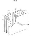
- Figure 5 is a perspective view of a steel plate structure having a bracket attached and Figure 6 is a side elevational view of a portion of a steel plate structure having a bracket attached .
- Figure 6 there are illustrated steel plates 12, structural members 14, struts 16, studs 18, a bracket 20, and bolts 22.
- fastening holes can be prepared, which penetrate the steel plates 12 and the structural members 14, so that the bracket 20 may be coupled to the steel plate 12 through the fastening holes using rivets or bolts 22, making it possible to support a heavy external device. That is, as illustrated in Figure 6 , fastening holes for securing the bracket 20 may be formed in portions of the steel plate 12 where a structural member 14 is rigidly joined, and the bracket 20 may be coupled through the fastening holes, to allow the steel plate 12 and the structural member 14 to support the external device together.
- This bracket 20 may be installed after the steel plate structure 10 is installed in the position for forming the wall but before casting the concrete, or may be installed after the concrete is cast and cured.
- bracket 20 it is also possible to install the bracket 20, to support a small external device, by forming fastening holes in portions of the steel plate 12 where a structural member 14 is not rigidly joined.
- a bracket may be installed utilizing the strengths of the steel plate and the structural member, so that heavy external devices, such as piping or electrical facilities, etc., may be supported effectively.
Landscapes
- Engineering & Computer Science (AREA)
- Architecture (AREA)
- Civil Engineering (AREA)
- Structural Engineering (AREA)
- Physics & Mathematics (AREA)
- Electromagnetism (AREA)
- Load-Bearing And Curtain Walls (AREA)
- Joining Of Building Structures In Genera (AREA)
- Panels For Use In Building Construction (AREA)
Description
- The present invention relates to a steel plate structure and a steel plate concrete wall. More particularly, the present invention relates to a steel plate structure and a steel plate concrete wall that include a load-bearing structural member, in addition to the steel plate and concrete, so as to reduce the thickness of the steel plate structure and steel plate concrete wall.
- As current structures are becoming taller and larger, it is becoming more important to provide higher strength and improved workability. For reinforced concrete structures, steel frame structures, and steel framed reinforced concrete structures, etc., which have been in common use until now, a structure may be constructed by assembling mold forms and steel rods or steel frames, etc., and casting the concrete directly at the construction site, so that the construction times may be increased and the quality may be made less reliable. As an alternate to such structures, the steel plate concrete structure (hereinafter referred to as "SC structure") is receiving attention, which is made by filling concrete inside steel plates so that the steel plates restrict the concrete, and which provides desirable properties in terms of strength, load-bearing, strain characteristics, and workability, etc.
- A prior art system is disclosed in the British patent application published as
GB2258669A - The SC structure is a system in which concrete is filled in between two steel plates, with studs and tie bars, etc., arranged such that the concrete and the steel materials move together, so that the steel materials and the concrete may move as an integrated body. In particular, the SC structure can be utilized in the construction of large structures such as nuclear power plants, etc., to reduce construction times by way of modularization.
Figure 1 illustrates a steel plate structure according to prior art, before the concrete is cast. Hereinafter, the steel structure made of steel plates, etc., before casting concrete in a SC structure wall will be referred to as a "steel plate structure." - The SC structure wall constructed using a steel plate structure according to prior art may be formed by vertically arranging
steel plates 102 at both surfaces of the wall that is to be formed, installing a number ofstuds 104 on the inner surfaces of thesteel plates 102 in order to facilitate the attachment between thesteel plates 102 and the concrete, connecting the twosteel plates 102 using rod-shaped struts 106 so as to secure the twosteel plates 102, and then casting concrete in the space between thesteel plates 102. When the inside of thesteel plates 102 is filled with concrete in the SC structure wall, even if a failure occurs in the concrete, thesteel plates 102 continue to restrict the concrete, to provide a greater level of load-bearing. Also, as the concrete is placed inside thesteel plates 102, the concrete can be prevented from being degraded by the external environment, so that the durability of the structure can be improved. - However, when using a steel plate structure according to prior art in forming a SC structure wall for a large structure, such as a skyscraper and a nuclear power plant, etc., the thickness of the wall having a SC structure may be increased, leading to spatial limitations. Also, due to the greater amount of loads that must be supported, the steel plates and concrete may have to be increased in thickness, where the greater thickness for the steel plates may lead to increased thermal deformations when welding the steel plates, as well as to a need for thermal post-treatment. In the case of a skyscraper or a nuclear power plant structure, in particular, the axial forces applied by the weight of the structure and the lateral forces caused by earthquakes must be resisted in an efficient manner, but as the concrete inside the steel materials has a low shear strength, the remaining shear strength has to be resisted by the steel plates. In order to bear the lateral forces caused by earthquakes, the thickness of the steel plates may have to be increased.
- Also, when modularizing the steel plate structure according to prior art and assembling the modules on site to form a wall, the steel plates of the unit modules may be welded together to attach the unit modules, or extra plates or couplers may be used in addition to the welding of the steel plates to enhance the adhesion strength between the unit modules. However, the extra plates or couplers may be exposed at the exterior surface to degrade the appearance, and the addition of secondary work may lead to longer construction periods. Furthermore, temporary reinforcement material may have to be additionally attached during the transporting of the unit modules to the construction site, in order to prevent deformations in the steel plate structure.
- When installing a bracket used for installing an external device, such as piping, etc., to the exterior of the SC structure wall, the bracket may be welded or coupled with bolts, but when a large external device having a heavy mass is installed to the bracket, local deformations may occur in the steel plate, and the load-bearing performance may be degraded, so that the external equipment may not be installed on the outside of the wall.
- Also, when casting concrete in the steel plate structure according to prior art, since the two steel plates are connected only by the rod-like struts, there is a risk that the steel plates may be deformed by the transverse pressure of the unhardened concrete.
- An aspect of the present invention is to provide a steel plate structure and a steel plate concrete wall that include load-bearing structural members, in addition to the steel plates and concrete, to reduce the thickness of the steel plate concrete wall and the thickness of the steel plates, while effectively resisting the axial forces or lateral forces acting on the wall.
- Another aspect of the present invention is to provide a steel plate structure and a steel plate concrete wall that allows easy attachment between the steel plate structure unit modules, in cases where the steel plate structure is manufactured as a unit module.
- Yet another aspect of the present invention is to provide a steel plate structure and a steel plate concrete wall that are capable of supporting a large external device having a heavy mass using the steel plates and structural members.
- An aspect of the present invention provides a steel plate structure according to claim 1.
- The structural member can be coupled to one side of the steel plate by welding.
- The structural member can include a pair of opposing structural members each coupled to one side of each of the pair of steel plates. In this case, the strut may be coupled between the pair of structural members. Here, the structural members and the strut may be H-beams.
- The structural member can be an H-beam, and the H-beam can be coupled such that a flange of the H-beam is coupled to one side of the steel plate.
- A fastening hole can be formed that penetrates the steel plate and the structural member. In this case, a bracket may further be included that is coupled to the other side of the steel plate through the fastening hole.
- Another aspect of the present invention provides a steel plate concrete wall according to claim 8.
- The steel plate concrete wall can further include studs protruding from one side of the steel plate.
- The structural member can be coupled to one side of the steel plate by welding.
- The structural member can include a pair of opposing structural members each coupled to one side of each of the pair of steel plates. In this case, the strut may be coupled between the pair of structural members. Here, the structural members and the strut may be H-beams.
- The structural member can be an H-beam, and the H-beam can be coupled such that a flange of the H-beam is coupled to one side of the steel plate.
- A fastening hole can be formed that penetrates the steel plate and the structural member. In this case, a bracket may further be included that is coupled to the other side of the steel plate through the fastening hole.
-
-
Figure 1 is a perspective view of a steel plate structure according to prior art, before casting concrete. -
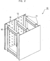
Figure 2 is a perspective view of a steel plate structure which does not form part of the present invention. -
Figure 3 is a side elevational view of a portion of a steel plate structure which does not form part of the present invention. -
Figure 4 is a plan view of a portion of a steel plate structure which does not form part of the present invention. -
Figure 5 is a perspective view of a steel plate structure having a bracket attached. -
Figure 6 is a side elevational view of a portion of a steel plate structure having a bracket attached. -
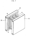
Figure 7 is a perspective view of a steel plate structure according to a disclosed embodiment of the present invention. -
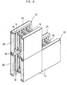
Figure 8 is a perspective view illustrating multiple steel plate structures coupled together according to the disclosed embodiment of the present invention. -
Figure 9 is a drawing illustrating the horizontal connectors of steel plate structures coupled together according to the disclosed embodiment of the present invention. -
Figure 10 is a drawing illustrating the vertical connectors of steel plate structures coupled together according to the disclosed embodiment of the present invention. -
Figure 11 is a drawing illustrating the construction of a steel plate concrete wall according to a disclosed embodiment of the present invention. - As the invention allows for various changes and numerous embodiments, particular embodiments will be illustrated in the drawings and described in detail in the written description. However, this is not intended to limit the present invention to particular modes of practice, and it is to be appreciated that all changes, equivalents, and substitutes that do not depart from the technical scope of the present invention are encompassed in the present invention. In the description of the present invention, certain detailed explanations of related art are omitted when it is deemed that they may unnecessarily obscure the essence of the invention.
- The terms used in the present specification are merely used to describe particular embodiments, and are not intended to limit the present invention. An expression used in the singular encompasses the expression of the plural, unless it has a clearly different meaning in the context. In the present specification, it is to be understood that the terms such as "including" or "having," etc., are intended to indicate the existence of the features, numbers, steps, actions, components, parts, or combinations thereof disclosed in the specification, and are not intended to preclude the possibility that one or more other features, numbers, steps, actions, components, parts, or combinations thereof may exist or may be added.
- The steel plate structure and steel plate concrete wall according to certain embodiments of the invention will be described below in more detail with reference to the accompanying drawings. Those components that are the same or are in correspondence are rendered the same reference numeral regardless of the figure number, and redundant explanations are omitted.
-
Figure 2 is a perspective view of a steel plate structure,Figure 3 is a side elevational view of a portion of a steel plate structure , andFigure 4 is a plan view of a portion of a steel plate structure. InFigure 2 through Figure 4 , there are illustrated asteel plate structure 10,steel plates 12,structural members 14, struts 16, andstuds 18. - The present embodiment can be composed of a pair of
steel plates 12 that are separated such that a predetermined space is provided,structural members 14 that are positioned in the space and are structurally rigidly joined to one side of asteel plate 12 in the direction of gravity, and struts 16 that maintain a separation distance between the pair ofsteel plates 12, so that the overall thickness of the steel plate concrete wall can be reduced, so as to allow efficient usage of space, and the thickness of the steel plates can be reduced, so as to reduce thermal deformations during welding attachments. Also, the axial forces or lateral forces acting on the wall can be effectively resisted. - The pair of steel plates may be installed with a distance from each other, to form a predetermined space between the
steel plates 12. The predetermined space can be where the concrete may later be cast, and the separation distance between thesteel plates 12 can be determined according to the load applied on the steel plate concrete wall. Thesteel plates 12 may be integrated with the concrete, after the forming of the steel plate concrete wall, to resist the load. Also, thesesteel plates 12 may restrict the concrete, so that even when the concrete inside undergoes failure, the concrete may be prevented from becoming detached, whereby the load-bearing capability of the steel plate concrete wall may be increased. - The
structural members 14 may exist within the predetermined space formed by the pair ofsteel plates 12, and may be structurally rigidly joined to one side of asteel plate 12 in the direction of gravity. Thestructural members 14 may resist the load applied on the steel plate concrete wall, together with thesteel plates 12 and concrete. Thestructural members 14 may be arranged in the direction of gravity, to resist the axial forces applied on the steel plate concrete wall, as well as the lateral forces caused by earthquakes, wind, etc. That is, thestructural members 14 may be coupled to one side of a steel plate in the longitudinal direction, to resist the load in the axial direction together with the concrete inside thesteel plate structure 10 and the steel plates, and as the steel plate concrete wall is rigidly joined to the foundation, to resist shear forces in the lateral directions caused by earthquakes, etc. Also, suchstructural members 14 may, together with thestuds 18 described later, contribute to the integrating of thesteel plates 12 and the concrete. Thus, thestructural members 14 may serve as structural materials together with the steel plates and the concrete to reduce the overall thickness of the steel plate concrete wall, and may thus be advantageous in forming the walls of a large structure, while thestructural members 14 may also reduce the thickness of the steel plates to reduce thermal deformations during welding attachments. - The
structural members 14 may be rigidly joined to thesteel plate 12, so that thestructural members 14 may move as an integrated body with thesteel plate 12. Examples of methods for rigidly joining asteel plate 12 with astructural member 14 include rigidly joining thesteel plate 12 and thestructural member 14 using high-tension bolts or rivets, and welding thestructural member 14 to thesteel plate 12, to allow integrated movement with thesteel plate 12. - According to the invention, H-beams are used for the
structural members 14, with the flanges of the H-beams coupled to one side of a steel plate to form a rigid joint. - The
structural members 14 can be structurally rigidly joined to thesteel plate 12, in order to prevent deformations in thesteel plate structure 10 due to eccentricity or contortion that may occur while transporting to the construction site after manufacture in a factory, and to prevent deformations in thesteel plate structure 10 due to transverse pressure applied by unhardened concrete when casting the concrete in thesteel plate structure 10. - The
structural members 14 can both be rigidly joined to just one of the twosteel plates 12 or can be rigidly joined to each of the twosteel plates 12. In the case where thestructural members 14 are rigidly joined to each of the twosteel plates 12, thestructural members 14 can be arranged opposite one another, as illustrated inFigure 2 . The number ofstructural members 14 coupled to one side of asteel plate 12 may be selected in correspondence to the load applied on the steel plate concrete wall. - As the
structural members 14 are structurally rigidly joined to thesteel plates 12, the combined effect of thesteel plates 12, concrete, andstructural members 14 may increase the strength against the load, so that a thick wall for a skyscraper structure or a power plant structure, etc., may be formed without increasing the thickness of thesteel plates 12. Therefore, as the strength against a large load may be increased without increasing the thickness of thesteel plates 12, the thickness of thesteel plates 12 can be minimized, to provide easier manufacture and installing of thesteel plate structure 10, and thesteel plate structure 10 can be modularized, allowing larger module sizes when performing the assembly on site. - The
struts 16 may maintain the separation distance between thesteel plates 12, whereby the pair ofsteel plates 12 may provide the predetermined space. Thestruts 16 can have both ends each coupled to each of the pair ofsteel plates 12, and in the case where thestructural members 14 are coupled to two steel plates in a zigzag configuration, it is possible to couple the ends of the struts to asteel plate 12 and astructural member 14, respectively. Also, in the case where thestructural members 14 are arranged opposite each other on twosteel plates 12, as illustrated inFigure 2 , thestruts 16 can be coupled to the opposingstructural members 14. - The
struts 16 may maintain the distance between thesteel plates 12 in consideration of the thickness of the wall, and may provide an adequate level of strength in consideration of transporting conditions, etc., of thesteel plate structure 10. In the case of a wall in a large structure, the increased thickness of the wall can entail a large separation distance between twosteel plates 12, and thus beams having a high strength may be used as the struts. In the present embodiment, thestructural members 14 and thestruts 16 are made from H-beams, where the factory manufacture of thesteel plate structure 10 can first include coupling thestruts 16 to thestructural members 14 to form a frame and then include attaching thesteel plates 12 to thestructural members 14, so that the manufacturing process may be shortened. - According to the size of the wall to be formed, the
steel plate structure 10 can be manufactured directly on site, or manufactured as a unit module at a factory, with the multiple unit modules assembled on site to form a wall. The case of forming thesteel plate structure 10 as a unit module will be described later in more detail with reference toFigure 7 . - The
studs 18 may be buried inside the concrete so as to allow thesteel plates 12 and the concrete to move in an integrated manner, in order that the combined effect of thesteel plates 12 and the concrete may resist external loads. Thestuds 18 may be buried uniformly over one side of asteel plate 12, so that the concrete and thesteel plate 12 may move as an integrated body over the entire surface. - As described above, in the case where the
structural members 14 are rigidly joined to one side of thesteel plate 12, thestructural members 14 may contribute to the integrating of the concrete with thesteel plate 12. If beams having a large area of contact with the concrete, such as H-beams, I-beams, C-beams, etc., are used for thestructural members 14, it may be possible to integrate thesteel plates 12 and the concrete with just thestructural members 14, and the coupling of thestuds 14 may be omitted. Of course, it is possible to reduce material costs by coupling only the required number ofstuds 18, in consideration of the degree by which thestructural members 14 contribute to the integration between thesteel plates 12 and the concrete. - In the case where the
steel plate structure 10 is to be manufactured on site to form a wall, thesteel plate structure 10 can be assembled over the foundation plate for forming the wall, after which concrete can be cast in between thesteel plates 12 to form a steel plate concrete wall. - Conversely, it is also possible to manufacture the
steel plate structure 10 according to the present embodiment as a unit module at a factory, transport the unit modules to the construction site, and attaching the unit modules on site to form a wall. In this case, since the correspondingstructural members 14 of the unit modules have to be connected in an integrated manner to transfer loads, the lower ends of thestructural members 14 of the unit modules arranged on top and the upper ends of thestructural members 14 of the unit modules arranged on the bottom may be given the same cross sections and afterwards rigidly joined, so that the forces in thestructural members 14 may be efficiently transferred to the ground. -
Figure 5 is a perspective view of a steel plate structure having a bracket attached andFigure 6 is a side elevational view of a portion of a steel plate structure having a bracket attached . InFigure 5 andFigure 6 , there are illustratedsteel plates 12,structural members 14, struts 16,studs 18, abracket 20, andbolts 22. - For a high-rise building, a factory building, a nuclear power plant structure, etc., there are many occasions when an external device, such as an electrical facility, communication facility, piping, etc., is installed on the wall, and in order to install an external device such as piping, etc., onto the outside of a steel plate concrete wall, a bracket for supporting the external device may be welded or coupled with
bolts 22 to asteel plate 12. However, when installing a large external device having a heavy mass onto thebracket 20, the mass of the external device may often cause local deformations in thesteel plate 12 and degrade the load-bearing performance. - Therefore, in the present embodiment, fastening holes can be prepared, which penetrate the
steel plates 12 and thestructural members 14, so that thebracket 20 may be coupled to thesteel plate 12 through the fastening holes using rivets orbolts 22, making it possible to support a heavy external device. That is, as illustrated inFigure 6 , fastening holes for securing thebracket 20 may be formed in portions of thesteel plate 12 where astructural member 14 is rigidly joined, and thebracket 20 may be coupled through the fastening holes, to allow thesteel plate 12 and thestructural member 14 to support the external device together. - This
bracket 20 may be installed after thesteel plate structure 10 is installed in the position for forming the wall but before casting the concrete, or may be installed after the concrete is cast and cured. - Of course, it is also possible to install the
bracket 20, to support a small external device, by forming fastening holes in portions of thesteel plate 12 where astructural member 14 is not rigidly joined. -
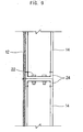
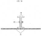
Figure 7 is a perspective view of a steel plate structure according to a disclosed embodiment of the present invention,Figure 8 is a perspective view illustrating multiple steel plate structures coupled together according to the disclosed embodiment of the present invention,Figure 9 is a drawing illustrating the horizontal connectors of steel plate structures coupled together according to the disclosed embodiment of the present invention, andFigure 10 is a drawing illustrating the vertical connectors of steel plate structures coupled together according to the disclosed embodiment of the present invention. InFigure 7 through Figure 10 , there are illustratedsteel plate structures 10,steel plates 12,structural members 14, struts 16,studs 18,horizontal connectors 24,vertical connectors 26, andbolts 22. - In the present embodiment, the
steel plate structures 10 may be manufactured at a factory as a unit module, after which the unit modules may be transported to the construction site, the unit modules for thesteel plate structures 10 may be assembled to manufacture bigger modules, the bigger modules may be hauled and installed in the final positions, and concrete may be cast, to complete a steel plate concrete wall. That is, as illustrated inFigure 8 , unit modules arranged up and down can be coupled usinghorizontal connectors 24, while unit modules arranged side by side can be coupled usingvertical connectors 26, and with a number of unit modules coupled together in accordance to the desired size of the wall, concrete can be cast in to form a steel plate concrete wall. - Multiple
structural members 14 can be coupled in thesteel plate structures 10 in predetermined intervals, andhorizontal connectors 24 are installed that interconnect the end portions of the multiplestructural members 14, to efficiently transfer the forces in thestructural members 14 and provide easier assembly between the unit modules of thesteel plate structures 10. - Also, for horizontal coupling between the
steel plate structures 10 implemented as unit modules,vertical connectors 26 are included that are each coupled in the direction of gravity to an end portion on one side of a steel plate. When attaching unit modules together, coupling thevertical connectors 26 to one another can increase the cross sectional area of the coupling surface, and when the attachment between unit modules is complete, thevertical connectors 26 may resist the loads applied on the steel plate concrete wall, together with thestructural members 14 described above. - The
horizontal connectors 24 can be for interconnecting unit modules that are arranged up and down, and thevertical connectors 26 can be for interconnecting unit modules that are arranged side by side, where the coupling betweenhorizontal connectors 24 and the coupling betweenvertical connectors 26 may form structurally rigid joints. - The
horizontal connectors 24 andvertical connectors 26 are attached to the end portions of the unit modules, and can perform a structural function of preventing deformations in the steel plates during the welding for attaching the steel plates of the unit modules together. - Examples of methods for coupling
horizontal connectors 24 to each other or couplingvertical connectors 26 to each other include rigid joining using high-tension bolts 22 or rivets, and rigid joining by welding. In the present embodiment, high-tension bolts 22 were used in coupling the unit modules together, as illustrated inFigure 9 andFigure 10 , to provide easier assembly on site. - C-beams are used for the
horizontal connectors 24 andvertical connectors 26. - As illustrated in
Figure 9 , in the present embodiment, H-beams are used for thestructural members 14, while C-beams are used for thehorizontal connectors 24, with the web of the end portion of the H-beam inserted in the channel portion of the C-beam such that the flanges of the C-beam face thestructural member 14, so that the attachment area between thestructural member 14 and thehorizontal connector 24 may be increased and the webs of the C-beams may be placed in surface contact with each other, in order that the forces in the members may readily be transferred. Fastening holes can be formed beforehand for coupling thehorizontal connectors 24 usingbolts 22 or rivets, when manufacturing thesteel plate structures 10 implemented as unit modules at the factory. - Also, as illustrated in
Figure 10 , C-beams are used for thevertical connectors 26, and the flanges of the C-beam may face thestructural member 14, so that the attachment area between the flange of the C-beam and the one side of the steel plate may be increased and the webs of the C-beams positioned side by side may be placed in surface contact with each other, in order that the forces in the members may readily be transferred. That is, when attaching the unit modules, coupling thevertical connectors 26 to one another can increase the cross sectional area of the coupling surface, to a form similar to an H-beam, and when the attachment between unit modules is complete, thevertical connectors 26 may resist the loads applied on the steel plate concrete wall, together with thestructural members 14 described above. - Fastening holes can be formed beforehand for coupling the
horizontal connectors 24 usingbolts 22 or rivets, when manufacturing thesteel plate structures 10, implemented as unit modules, at the factory. - As described above, fastening holes may be prepared, which penetrate the
steel plate 12 and thestructural member 14, so that a bracket may be coupled to thesteel plate 12 through the fastening holes using rivets or bolts, whereby thesteel plate 12 and thestructural member 14 rigidly joined to thesteel plate 12 may support an external device together, making it possible to support an external device having a heavy mass. -
Figure 11 is a drawing illustrating the construction of a steel plate concrete wall according to a disclosed embodiment of the present invention. InFigure 11 , there are illustratedsteel plate structures 10, concrete 30, and aconcrete supply part 28. - With the
steel plate structures 10 implemented as a unit module, several unit modules can be assembled to form a wall of a predetermined size. That is, thesteel plate structure 10 implemented as unit modules may be manufactured in a required number, after which the unit modules may be transported to the construction site, thesteel plate structures 10 as unit modules may be assembled into a bigger module, the bigger modules may be hauled and installed in the final positions, and concrete 30 may be cast by way of theconcrete supply part 28, to form a steel plate concrete wall. - Manufacturing the
steel plate structures 10 in a factory may allow easier quality management to provide high-qualitysteel plate structures 10, and as the work on site may be minimized, the construction time can be reduced. - While the invention has been described in detail with reference to particular embodiments, the embodiments are for illustrative purposes only and do not limit the invention. It is to be appreciated that those skilled in the art can change or modify the embodiments without departing from the scope of the invention.
- By utilizing load-bearing structural members together with the steel plates and concrete, the overall thickness of the steel plate concrete wall can be reduced, to allow a more efficient use of space.
- Also, the thickness of the steel plates can be reduced, allowing better welding properties and larger unit module sizes.
- Also, the axial forces or lateral forces applied on the steel plate concrete wall may be effectively resisted.
- Furthermore, in the case where the steel plate structure is implemented as a unit module, horizontal connectors or vertical connectors may be arranged at the end portions of the steel plates, to facilitate the attaching between unit modules and allow the forces in the structural members to be transferred directly between unit modules, whereby the strength of the wall may be increased.
- Also, a bracket may be installed utilizing the strengths of the steel plate and the structural member, so that heavy external devices, such as piping or electrical facilities, etc., may be supported effectively.
| 10: | steel plate structure | 12: | steel plate |
| 14: | structural member | 16: | strut |
| 18: | stud | 20: | bracket |
| 22: | bolt | 24: | horizontal connector |
| 26: | vertical connector | 28: | concrete supply part |
| 30: | concrete |
Claims (14)
- A steel plate structure (10) comprising:a pair of steel plates (12) separated such that a predetermined space is provided;a plurality of structural members (14), each being positioned in the predetermined space and structurally rigidly joined to one side of the steel plates in a direction of gravity; andStruts (16) coupled between the structural members (14), said struts and said structural members being H-beams and maintaining a separation distance between the pair of steel plates (12),
andfurther comprising a horizontal connector (24) interconnecting end portions of the plurality of structural members (14),wherein the horizontal connector (24) is a C-beam and coupled to end portions of one side of the steel plate, andthe C-beam is coupled such that a flange of the C-beam faces the structural member,further comprising:a vertical connector (26) coupled to end portions of one side of the steel plate in a direction of gravity,wherein the vertical connector (26) is a C-beam, andthe C-beam is coupled such that a flange of the C-beam faces the structural member. - The steel plate structure (10) according to claim 1, further comprising studs (18) protruding from one side of the steel plate (12).
- The steel plate structure (10) according to claim 1, wherein the structural member (14) is coupled to one side of the steel plate (12) by welding.
- The steel plate structure (10) according to claim 1, wherein the structural member (14) includes a pair of opposing structural members (14) each coupled to one side of each of the pair of steel plates (12).
- The steel plate structure (10) according to claim 1, wherein the structural member (14) is an H-beam, and
the H-beam is coupled such that a flange of the H-beam is coupled to one side of the steel plate (12). - The steel plate structure (10) according to claim 1, further comprising:a fastening hole penetrating the steel plate (12) and the structural member (14).
- The steel plate structure (10) according to claim 6, further comprising:a bracket (20) coupled to the other side of the steel plate (12) through the fastening hole.
- A steel plate (12) concrete wall comprising:a pair of steel plates (12) separated such that a predetermined space is provided;a plurality of structural members (14), each being positioned in the predetermined space and structurally rigidly joined to one side of each of the steel plates (12) in a direction of gravity;a strut (16) coupled between the structural members (14), said strut and structural members being H-beams and maintaining a separation distance between the pair of steel plates (12); andconcrete (30) interposed inside the predetermined space, andfurther comprising a horizontal connector (24) interconnecting end portions of the plurality of structural members,wherein the horizontal connector (24) is a C-beam and coupled to end portions of one side of the steel plate, andthe C-beam is coupled such that a flange of the C-beam faces the structural member (14),further comprising:a vertical connector (26) coupled to one side of the steel plate (12) in a direction of gravity,wherein the vertical connector (26) is a C-beam, andthe C-beam is coupled such that a flange of the C-beam faces the structural member (14).
- The steel plate (12) concrete wall according to claim 8, further comprising studs (18) protruding from one side of the steel plate (12).
- The steel plate (12) concrete wall according to claim 8, wherein the structural member (14) is coupled to one side of the steel plate (12) by welding.
- The steel plate (12) concrete wall according to claim 8, wherein the structural member (14) includes a pair of opposing structural members (14) each coupled to one side of each of the pair of steel plates (12).
- The steel plate (12) concrete wall according to claim 8, wherein the structural member (14) is an H-beam, and
the H-beam is coupled such that a flange of the H-beam is coupled to one side of the steel plate (12). - The steel plate (12) concrete wall according to claim 8, further comprising:a fastening hole penetrating the steel plate (12) and the structural member (14).
- The steel plate (12) concrete wall according to claim 13, wherein further comprising:a bracket (20) coupled to the other side of the steel plate (12) through the fastening hole.
Applications Claiming Priority (2)
| Application Number | Priority Date | Filing Date | Title |
|---|---|---|---|
| KR1020070063845A KR100849711B1 (en) | 2007-06-27 | 2007-06-27 | Steel plate structure and steel plate concrete wall |
| PCT/KR2008/003697 WO2009002112A2 (en) | 2007-06-27 | 2008-06-26 | Steel plate structure and steel plate concrete wall |
Publications (3)
| Publication Number | Publication Date |
|---|---|
| EP2167750A2 EP2167750A2 (en) | 2010-03-31 |
| EP2167750A4 EP2167750A4 (en) | 2013-11-13 |
| EP2167750B1 true EP2167750B1 (en) | 2016-06-15 |
Family
ID=39881016
Family Applications (1)
| Application Number | Title | Priority Date | Filing Date |
|---|---|---|---|
| EP08778388.2A Active EP2167750B1 (en) | 2007-06-27 | 2008-06-26 | Steel plate structure and steel plate concrete wall |
Country Status (7)
| Country | Link |
|---|---|
| US (2) | US20100132291A1 (en) |
| EP (1) | EP2167750B1 (en) |
| KR (1) | KR100849711B1 (en) |
| CN (1) | CN101688395B (en) |
| HU (1) | HUE030423T2 (en) |
| PL (1) | PL2167750T3 (en) |
| WO (1) | WO2009002112A2 (en) |
Families Citing this family (36)
| Publication number | Priority date | Publication date | Assignee | Title |
|---|---|---|---|---|
| KR101024262B1 (en) * | 2008-07-30 | 2011-03-29 | 한국전력기술 주식회사 | Steel plate structure |
| US9388561B2 (en) * | 2009-07-15 | 2016-07-12 | Frank Johnson | Modular construction mold apparatus and method for constructing concrete buildings and structures |
| EP2620563A4 (en) * | 2010-09-24 | 2014-07-16 | Mitsubishi Heavy Ind Ltd | Accessory attaching structure, design system and design method of steel plate reinforced concrete structure, construction method of steel plate reinforced concrete structure, and steel plate reinforced concrete structure |
| KR101367424B1 (en) * | 2011-12-30 | 2014-02-27 | 롯데건설 주식회사 | Conjunction Structure between box-shaped steel member and RC wall |
| CN104358333A (en) * | 2014-10-28 | 2015-02-18 | 四川华铁钢结构有限公司 | Steel structure composite wall with high stability |
| CN104358310B (en) * | 2014-10-28 | 2017-01-11 | 四川华铁钢结构有限公司 | High-strength house unit with H-shaped steel structure frame |
| CN104358462B (en) * | 2014-10-28 | 2016-11-30 | 四川华铁钢结构有限公司 | A kind of polyester vinyl wallboard fire-retardant composite house structure |
| JP6315277B2 (en) * | 2014-11-26 | 2018-04-25 | 清水建設株式会社 | Steel plate concrete structure |
| CN104594645B (en) * | 2015-01-15 | 2017-07-28 | 庄学阳 | The construction method of wall panel fixed mount |
| CN104775578A (en) * | 2015-02-10 | 2015-07-15 | 湖北弘毅建设有限公司 | Prefabricated metal finish concrete outer wall plate |
| CN105401693A (en) * | 2015-12-01 | 2016-03-16 | 苏州天地彩钢制造有限公司 | Symmetrical steel structure |
| CN105780969A (en) * | 2016-03-31 | 2016-07-20 | 初明进 | I-shaped steel member |
| CN106088412A (en) * | 2016-06-02 | 2016-11-09 | 初明进 | L-type steel beam column |
| CN105971165A (en) * | 2016-06-02 | 2016-09-28 | 初明进 | L-shaped steel member |
| FR3060622B1 (en) * | 2016-12-21 | 2020-10-02 | Electricite De France | PERMANENT CONCRETE FORMWORK AND PROCESS FOR MANUFACTURING A METAL-CONCRETE COMPOSITE STRUCTURE USING SUCH FORMWORK |
| CN107217737A (en) * | 2017-06-28 | 2017-09-29 | 浙江绿筑集成科技有限公司 | A kind of faced wall steel beam structure |
| US10538907B2 (en) * | 2017-08-01 | 2020-01-21 | SkyStone Group LLC | Modular assemblies and methods of construction thereof |
| CN107489212B (en) * | 2017-09-27 | 2023-01-03 | 杭州铁木辛柯建筑结构设计事务所有限公司 | Bearing-force-free shear-resistant buckling steel plate shear wall |
| CN108756020A (en) * | 2018-06-01 | 2018-11-06 | 湖南飞扬建设工程有限公司 | A kind of foamed concrete composite insulation wall |
| CN108620796B (en) * | 2018-07-13 | 2020-12-15 | 中国核工业二三建设有限公司 | Auxiliary tooling for longitudinal seam welding of SC structure of shielded workshop |
| KR102198165B1 (en) * | 2018-09-04 | 2021-01-04 | 백두산업 주식회사 | Aseismicity wall permanent form unit and Wall construction method using the same |
| US11352786B2 (en) * | 2019-08-19 | 2022-06-07 | WSP USA, Inc. | Constructing buildings with modular wall structure |
| CN111042385A (en) * | 2019-12-29 | 2020-04-21 | 北京工业大学 | An assembled double-layer steel plate composite shear wall |
| CN111636574B (en) * | 2020-06-10 | 2024-08-06 | 北京建谊投资发展(集团)有限公司 | Combined construction method of steel plate wall and steel frame beam |
| CN112064784A (en) * | 2020-09-26 | 2020-12-11 | 深圳千里马装饰集团有限公司 | Assembled light steel structure residential building system |
| CN112726880A (en) * | 2020-12-28 | 2021-04-30 | 同济大学 | Rectangular steel pipe-corrugated steel plate combined wall steel coupling beam coupled wall |
| FI130581B (en) * | 2021-02-01 | 2023-11-23 | Mika Rautiainen | Reactor for the production of biogas through anaerobic decomposition of bio-raw materials |
| CN113107108A (en) * | 2021-03-20 | 2021-07-13 | 北京工业大学 | Double-steel-plate concrete composite wall with T-shaped stiffening ribs and U-shaped pull rods |
| CN113107109A (en) * | 2021-03-20 | 2021-07-13 | 北京工业大学 | U-shaped pull rod staggered double-steel-plate concrete combined shear wall |
| CN113914504B (en) * | 2021-11-22 | 2022-05-17 | 广东思哲设计院有限公司 | Assembled wall body for old city reconstruction |
| CN114150795A (en) * | 2021-12-14 | 2022-03-08 | 秦长城新型建材(天津)有限公司 | Light cast-in-place high-strength formwork disassembly-free wall and construction method thereof |
| KR102749879B1 (en) * | 2022-10-11 | 2025-01-03 | 한국수력원자력 주식회사 | Steel plate concrete structure precision connection system and method for small modular reactor |
| KR102749873B1 (en) * | 2022-10-11 | 2025-01-03 | 한국수력원자력 주식회사 | Field connection system and method of steel-plate concrete module for small modular reactor |
| JP2025123974A (en) * | 2024-02-13 | 2025-08-25 | 鹿島建設株式会社 | Wall construction method and wall |
| JP2025125156A (en) * | 2024-02-15 | 2025-08-27 | 鹿島建設株式会社 | wall |
| CN118756851B (en) * | 2024-07-22 | 2025-12-02 | 华侨大学 | A lattice-type steel-concrete shear wall and its construction method |
Family Cites Families (20)
| Publication number | Priority date | Publication date | Assignee | Title |
|---|---|---|---|---|
| US4178729A (en) | 1978-05-15 | 1979-12-18 | Economy Forms Corporation | Wall structure for a nuclear reactor containment housing |
| JPS5770495A (en) * | 1980-10-21 | 1982-04-30 | Ishikawajima Harima Heavy Ind | Method of constructing atomic power plant building |
| JPS59116090A (en) | 1982-12-23 | 1984-07-04 | 清水建設株式会社 | Wall structure in reactor building and the like |
| JPS59233075A (en) * | 1983-06-15 | 1984-12-27 | 株式会社東芝 | Construction of shield wall body equipped with lining |
| TW299381B (en) * | 1991-08-13 | 1997-03-01 | Mitsubishi Heavy Ind Ltd | |
| US5741571A (en) | 1994-03-31 | 1998-04-21 | British Steel Plc | Double skin composite panels |
| JPH10160881A (en) * | 1996-11-29 | 1998-06-19 | Toshiba Corp | Nuclear power plant building structure and building construction method |
| US6041561A (en) * | 1997-08-22 | 2000-03-28 | Wayne Leblang | Self-contained molded pre-fabricated building panel and method of making the same |
| JP2000170285A (en) * | 1998-12-08 | 2000-06-20 | Kajima Corp | Joint method and joint structure of steel plate concrete structure wall |
| KR100379740B1 (en) * | 1999-11-13 | 2003-04-10 | 김태한 | Framework |
| CN1156633C (en) * | 2000-01-24 | 2004-07-07 | 许琦 | Steel skeleton building structure |
| KR20030052872A (en) * | 2001-12-21 | 2003-06-27 | 재단법인 포항산업과학연구원 | Steel mold for bridge scaffolding and steel housing using the steel mold |
| US6570950B1 (en) | 2002-03-11 | 2003-05-27 | Westinghouse Electric Company Llc | Nuclear plant containment with prefabricated component support structure |
| KR20030036380A (en) * | 2003-03-20 | 2003-05-09 | 김태한 | An iron plate frame work |
| US20040255535A1 (en) * | 2003-06-19 | 2004-12-23 | Herren Thomas R. | Multi-purpose construction assembly and method |
| JP4182425B2 (en) * | 2003-09-17 | 2008-11-19 | 東芝プラントシステム株式会社 | Embedded electric circuit for steel plate concrete structure |
| DK1644592T3 (en) * | 2003-11-03 | 2008-05-13 | Polyfinance Coffor Holding S A | Formwork with high resistance to concrete walls |
| US20070044392A1 (en) * | 2004-11-12 | 2007-03-01 | Leblang Dennis W | Modular building construction employing concrete mold assembly |
| KR100686468B1 (en) * | 2004-12-17 | 2007-02-27 | 이창남 | Steel concrete wall composed of expanded channel and y type side plate |
| JP2007063954A (en) * | 2005-09-02 | 2007-03-15 | Takenaka Komuten Co Ltd | Method of forming steel plate concrete |
-
2007
- 2007-06-27 KR KR1020070063845A patent/KR100849711B1/en active Active
-
2008
- 2008-06-26 WO PCT/KR2008/003697 patent/WO2009002112A2/en not_active Ceased
- 2008-06-26 US US12/452,300 patent/US20100132291A1/en not_active Abandoned
- 2008-06-26 EP EP08778388.2A patent/EP2167750B1/en active Active
- 2008-06-26 CN CN200880021644.1A patent/CN101688395B/en active Active
- 2008-06-26 PL PL08778388.2T patent/PL2167750T3/en unknown
- 2008-06-26 HU HUE08778388A patent/HUE030423T2/en unknown
-
2015
- 2015-02-12 US US14/621,213 patent/US9631363B2/en active Active
Also Published As
| Publication number | Publication date |
|---|---|
| KR100849711B1 (en) | 2008-08-01 |
| US20100132291A1 (en) | 2010-06-03 |
| WO2009002112A3 (en) | 2009-02-26 |
| WO2009002112A2 (en) | 2008-12-31 |
| CN101688395A (en) | 2010-03-31 |
| EP2167750A4 (en) | 2013-11-13 |
| US9631363B2 (en) | 2017-04-25 |
| US20150159372A1 (en) | 2015-06-11 |
| HUE030423T2 (en) | 2017-05-29 |
| PL2167750T3 (en) | 2016-12-30 |
| CN101688395B (en) | 2014-12-31 |
| EP2167750A2 (en) | 2010-03-31 |
Similar Documents
| Publication | Publication Date | Title |
|---|---|---|
| US9631363B2 (en) | Steel plate structure and steel plate concrete wall | |
| WO2010013858A1 (en) | Steel plate structure and steel plate concrete wall | |
| WO2010013857A1 (en) | Steel plate structure and steel plate concrete wall | |
| WO2009011516A2 (en) | Form with reinforcing bars, non-support form system and non-support construction method using the same | |
| KR100713692B1 (en) | Prestressed connection type pier using internally confined hollow concrete filling unit and construction method | |
| KR100946940B1 (en) | Shear reinforcement joint structure between steel pipe column and reinforced concrete flat slab | |
| KR101211691B1 (en) | Hybrd-structure beam using gusset connection plate | |
| KR101182084B1 (en) | Method making the prestressed precast girder of Rahmen structure induced a compressive stress by a support with hinge and method constructing Rahmen bridge thereof | |
| KR101031299B1 (en) | Bonding structure and unit method of unit unit module for integral behavior of modular buildings | |
| KR101632681B1 (en) | Joint structure of modular system using the plate, Construction method and Modular system thereby | |
| WO2011060360A1 (en) | Assembly module for composite wall and method of assembly | |
| KR100939970B1 (en) | A method of constructing a complex girder and its structure | |
| KR20220138722A (en) | Connection Structure Between Steel-Concrete Hybrid Columns Using Vetical Member | |
| KR101049963B1 (en) | Steel plate structure and construction method of wall-slab joint structure using same | |
| CN107023020B (en) | Horizontal internal support system of deep foundation pit assembled type combined steel structure and construction method thereof | |
| CN112302162B (en) | Fabricated chord-supported concrete transfer floor structure and construction method thereof | |
| WO2010013859A1 (en) | Steel plate structure | |
| KR101083062B1 (en) | Compound beam | |
| CN222909028U (en) | Steel connection boxes and prefabricated frame columns in beam-column joints | |
| KR20070020825A (en) | Prefabricated bridge using internally confined hollow concrete filling unit and construction method | |
| CN224092695U (en) | Beam column connection node structure of precast beam and hidden bracket precast column | |
| CN219931332U (en) | Assembled steel tube concrete damping wall structure and system | |
| CN120556779B (en) | Connection node of modular stacked building | |
| CN121519609B (en) | Gravity wall-barrel structure system and design method | |
| KR101528046B1 (en) | Outrigger connection box and connection structure of the same |
Legal Events
| Date | Code | Title | Description |
|---|---|---|---|
| PUAI | Public reference made under article 153(3) epc to a published international application that has entered the european phase |
Free format text: ORIGINAL CODE: 0009012 |
|
| 17P | Request for examination filed |
Effective date: 20091221 |
|
| AK | Designated contracting states |
Kind code of ref document: A2 Designated state(s): AT BE BG CH CY CZ DE DK EE ES FI FR GB GR HR HU IE IS IT LI LT LU LV MC MT NL NO PL PT RO SE SI SK TR |
|
| AX | Request for extension of the european patent |
Extension state: AL BA MK RS |
|
| DAX | Request for extension of the european patent (deleted) | ||
| TPAC | Observations filed by third parties |
Free format text: ORIGINAL CODE: EPIDOSNTIPA |
|
| A4 | Supplementary search report drawn up and despatched |
Effective date: 20131011 |
|
| RIC1 | Information provided on ipc code assigned before grant |
Ipc: E04B 2/86 20060101AFI20131007BHEP |
|
| 17Q | First examination report despatched |
Effective date: 20140903 |
|
| GRAP | Despatch of communication of intention to grant a patent |
Free format text: ORIGINAL CODE: EPIDOSNIGR1 |
|
| INTG | Intention to grant announced |
Effective date: 20160111 |
|
| GRAS | Grant fee paid |
Free format text: ORIGINAL CODE: EPIDOSNIGR3 |
|
| GRAA | (expected) grant |
Free format text: ORIGINAL CODE: 0009210 |
|
| AK | Designated contracting states |
Kind code of ref document: B1 Designated state(s): AT BE BG CH CY CZ DE DK EE ES FI FR GB GR HR HU IE IS IT LI LT LU LV MC MT NL NO PL PT RO SE SI SK TR |
|
| REG | Reference to a national code |
Ref country code: CH Ref legal event code: EP Ref country code: GB Ref legal event code: FG4D |
|
| REG | Reference to a national code |
Ref country code: FR Ref legal event code: PLFP Year of fee payment: 9 |
|
| REG | Reference to a national code |
Ref country code: IE Ref legal event code: FG4D |
|
| REG | Reference to a national code |
Ref country code: AT Ref legal event code: REF Ref document number: 806591 Country of ref document: AT Kind code of ref document: T Effective date: 20160715 |
|
| REG | Reference to a national code |
Ref country code: DE Ref legal event code: R096 Ref document number: 602008044721 Country of ref document: DE |
|
| REG | Reference to a national code |
Ref country code: RO Ref legal event code: EPE |
|
| REG | Reference to a national code |
Ref country code: SE Ref legal event code: TRGR |
|
| REG | Reference to a national code |
Ref country code: LT Ref legal event code: MG4D |
|
| REG | Reference to a national code |
Ref country code: NL Ref legal event code: MP Effective date: 20160615 |
|
| PG25 | Lapsed in a contracting state [announced via postgrant information from national office to epo] |
Ref country code: LT Free format text: LAPSE BECAUSE OF FAILURE TO SUBMIT A TRANSLATION OF THE DESCRIPTION OR TO PAY THE FEE WITHIN THE PRESCRIBED TIME-LIMIT Effective date: 20160615 Ref country code: NO Free format text: LAPSE BECAUSE OF FAILURE TO SUBMIT A TRANSLATION OF THE DESCRIPTION OR TO PAY THE FEE WITHIN THE PRESCRIBED TIME-LIMIT Effective date: 20160915 |
|
| REG | Reference to a national code |
Ref country code: AT Ref legal event code: MK05 Ref document number: 806591 Country of ref document: AT Kind code of ref document: T Effective date: 20160615 |
|
| PG25 | Lapsed in a contracting state [announced via postgrant information from national office to epo] |
Ref country code: NL Free format text: LAPSE BECAUSE OF FAILURE TO SUBMIT A TRANSLATION OF THE DESCRIPTION OR TO PAY THE FEE WITHIN THE PRESCRIBED TIME-LIMIT Effective date: 20160615 Ref country code: LV Free format text: LAPSE BECAUSE OF FAILURE TO SUBMIT A TRANSLATION OF THE DESCRIPTION OR TO PAY THE FEE WITHIN THE PRESCRIBED TIME-LIMIT Effective date: 20160615 Ref country code: GR Free format text: LAPSE BECAUSE OF FAILURE TO SUBMIT A TRANSLATION OF THE DESCRIPTION OR TO PAY THE FEE WITHIN THE PRESCRIBED TIME-LIMIT Effective date: 20160916 Ref country code: HR Free format text: LAPSE BECAUSE OF FAILURE TO SUBMIT A TRANSLATION OF THE DESCRIPTION OR TO PAY THE FEE WITHIN THE PRESCRIBED TIME-LIMIT Effective date: 20160615 |
|
| PG25 | Lapsed in a contracting state [announced via postgrant information from national office to epo] |
Ref country code: BE Free format text: LAPSE BECAUSE OF NON-PAYMENT OF DUE FEES Effective date: 20160630 |
|
| REG | Reference to a national code |
Ref country code: DE Ref legal event code: R119 Ref document number: 602008044721 Country of ref document: DE |
|
| PG25 | Lapsed in a contracting state [announced via postgrant information from national office to epo] |
Ref country code: EE Free format text: LAPSE BECAUSE OF FAILURE TO SUBMIT A TRANSLATION OF THE DESCRIPTION OR TO PAY THE FEE WITHIN THE PRESCRIBED TIME-LIMIT Effective date: 20160615 Ref country code: IS Free format text: LAPSE BECAUSE OF FAILURE TO SUBMIT A TRANSLATION OF THE DESCRIPTION OR TO PAY THE FEE WITHIN THE PRESCRIBED TIME-LIMIT Effective date: 20161015 Ref country code: IT Free format text: LAPSE BECAUSE OF FAILURE TO SUBMIT A TRANSLATION OF THE DESCRIPTION OR TO PAY THE FEE WITHIN THE PRESCRIBED TIME-LIMIT Effective date: 20160615 |
|
| REG | Reference to a national code |
Ref country code: CH Ref legal event code: PL |
|
| PG25 | Lapsed in a contracting state [announced via postgrant information from national office to epo] |
Ref country code: BE Free format text: LAPSE BECAUSE OF FAILURE TO SUBMIT A TRANSLATION OF THE DESCRIPTION OR TO PAY THE FEE WITHIN THE PRESCRIBED TIME-LIMIT Effective date: 20160615 Ref country code: AT Free format text: LAPSE BECAUSE OF FAILURE TO SUBMIT A TRANSLATION OF THE DESCRIPTION OR TO PAY THE FEE WITHIN THE PRESCRIBED TIME-LIMIT Effective date: 20160615 Ref country code: ES Free format text: LAPSE BECAUSE OF FAILURE TO SUBMIT A TRANSLATION OF THE DESCRIPTION OR TO PAY THE FEE WITHIN THE PRESCRIBED TIME-LIMIT Effective date: 20160615 Ref country code: PT Free format text: LAPSE BECAUSE OF FAILURE TO SUBMIT A TRANSLATION OF THE DESCRIPTION OR TO PAY THE FEE WITHIN THE PRESCRIBED TIME-LIMIT Effective date: 20161017 |
|
| REG | Reference to a national code |
Ref country code: IE Ref legal event code: MM4A |
|
| PG25 | Lapsed in a contracting state [announced via postgrant information from national office to epo] |
Ref country code: MC Free format text: LAPSE BECAUSE OF FAILURE TO SUBMIT A TRANSLATION OF THE DESCRIPTION OR TO PAY THE FEE WITHIN THE PRESCRIBED TIME-LIMIT Effective date: 20160615 |
|
| PLBE | No opposition filed within time limit |
Free format text: ORIGINAL CODE: 0009261 |
|
| STAA | Information on the status of an ep patent application or granted ep patent |
Free format text: STATUS: NO OPPOSITION FILED WITHIN TIME LIMIT |
|
| PG25 | Lapsed in a contracting state [announced via postgrant information from national office to epo] |
Ref country code: LI Free format text: LAPSE BECAUSE OF NON-PAYMENT OF DUE FEES Effective date: 20160630 Ref country code: DE Free format text: LAPSE BECAUSE OF NON-PAYMENT OF DUE FEES Effective date: 20170103 Ref country code: CH Free format text: LAPSE BECAUSE OF NON-PAYMENT OF DUE FEES Effective date: 20160630 |
|
| 26N | No opposition filed |
Effective date: 20170316 |
|
| REG | Reference to a national code |
Ref country code: HU Ref legal event code: AG4A Ref document number: E030423 Country of ref document: HU |
|
| PG25 | Lapsed in a contracting state [announced via postgrant information from national office to epo] |
Ref country code: IE Free format text: LAPSE BECAUSE OF NON-PAYMENT OF DUE FEES Effective date: 20160626 Ref country code: DK Free format text: LAPSE BECAUSE OF FAILURE TO SUBMIT A TRANSLATION OF THE DESCRIPTION OR TO PAY THE FEE WITHIN THE PRESCRIBED TIME-LIMIT Effective date: 20160615 |
|
| REG | Reference to a national code |
Ref country code: FR Ref legal event code: PLFP Year of fee payment: 10 |
|
| PG25 | Lapsed in a contracting state [announced via postgrant information from national office to epo] |
Ref country code: SI Free format text: LAPSE BECAUSE OF FAILURE TO SUBMIT A TRANSLATION OF THE DESCRIPTION OR TO PAY THE FEE WITHIN THE PRESCRIBED TIME-LIMIT Effective date: 20160615 |
|
| PG25 | Lapsed in a contracting state [announced via postgrant information from national office to epo] |
Ref country code: CY Free format text: LAPSE BECAUSE OF FAILURE TO SUBMIT A TRANSLATION OF THE DESCRIPTION OR TO PAY THE FEE WITHIN THE PRESCRIBED TIME-LIMIT Effective date: 20160615 |
|
| REG | Reference to a national code |
Ref country code: FR Ref legal event code: PLFP Year of fee payment: 11 |
|
| PG25 | Lapsed in a contracting state [announced via postgrant information from national office to epo] |
Ref country code: LU Free format text: LAPSE BECAUSE OF NON-PAYMENT OF DUE FEES Effective date: 20160626 Ref country code: MT Free format text: LAPSE BECAUSE OF NON-PAYMENT OF DUE FEES Effective date: 20160630 |
|
| PG25 | Lapsed in a contracting state [announced via postgrant information from national office to epo] |
Ref country code: BG Free format text: LAPSE BECAUSE OF FAILURE TO SUBMIT A TRANSLATION OF THE DESCRIPTION OR TO PAY THE FEE WITHIN THE PRESCRIBED TIME-LIMIT Effective date: 20160615 |
|
| PGFP | Annual fee paid to national office [announced via postgrant information from national office to epo] |
Ref country code: FI Payment date: 20250417 Year of fee payment: 18 |
|
| PGFP | Annual fee paid to national office [announced via postgrant information from national office to epo] |
Ref country code: PL Payment date: 20250417 Year of fee payment: 18 |
|
| PGFP | Annual fee paid to national office [announced via postgrant information from national office to epo] |
Ref country code: GB Payment date: 20250416 Year of fee payment: 18 |
|
| PGFP | Annual fee paid to national office [announced via postgrant information from national office to epo] |
Ref country code: HU Payment date: 20250520 Year of fee payment: 18 Ref country code: FR Payment date: 20250416 Year of fee payment: 18 |
|
| PGFP | Annual fee paid to national office [announced via postgrant information from national office to epo] |
Ref country code: RO Payment date: 20250616 Year of fee payment: 18 |
|
| PGFP | Annual fee paid to national office [announced via postgrant information from national office to epo] |
Ref country code: TR Payment date: 20250619 Year of fee payment: 18 Ref country code: SK Payment date: 20250417 Year of fee payment: 18 |
|
| PGFP | Annual fee paid to national office [announced via postgrant information from national office to epo] |
Ref country code: CZ Payment date: 20250612 Year of fee payment: 18 |
|
| PGFP | Annual fee paid to national office [announced via postgrant information from national office to epo] |
Ref country code: SE Payment date: 20250416 Year of fee payment: 18 |