EP2167226B1 - Wall system for catalytic beds of synthesis reactors and relative production process - Google Patents
Wall system for catalytic beds of synthesis reactors and relative production process Download PDFInfo
- Publication number
- EP2167226B1 EP2167226B1 EP20080773755 EP08773755A EP2167226B1 EP 2167226 B1 EP2167226 B1 EP 2167226B1 EP 20080773755 EP20080773755 EP 20080773755 EP 08773755 A EP08773755 A EP 08773755A EP 2167226 B1 EP2167226 B1 EP 2167226B1
- Authority
- EP
- European Patent Office
- Prior art keywords
- wall
- slits
- walls
- gases
- catalytic bed
- Prior art date
- Legal status (The legal status is an assumption and is not a legal conclusion. Google has not performed a legal analysis and makes no representation as to the accuracy of the status listed.)
- Active
Links
Images




Classifications
-
- B—PERFORMING OPERATIONS; TRANSPORTING
- B01—PHYSICAL OR CHEMICAL PROCESSES OR APPARATUS IN GENERAL
- B01J—CHEMICAL OR PHYSICAL PROCESSES, e.g. CATALYSIS OR COLLOID CHEMISTRY; THEIR RELEVANT APPARATUS
- B01J19/00—Chemical, physical or physico-chemical processes in general; Their relevant apparatus
- B01J19/0053—Details of the reactor
-
- B—PERFORMING OPERATIONS; TRANSPORTING
- B01—PHYSICAL OR CHEMICAL PROCESSES OR APPARATUS IN GENERAL
- B01J—CHEMICAL OR PHYSICAL PROCESSES, e.g. CATALYSIS OR COLLOID CHEMISTRY; THEIR RELEVANT APPARATUS
- B01J8/00—Chemical or physical processes in general, conducted in the presence of fluids and solid particles; Apparatus for such processes
- B01J8/02—Chemical or physical processes in general, conducted in the presence of fluids and solid particles; Apparatus for such processes with stationary particles, e.g. in fixed beds
- B01J8/0207—Chemical or physical processes in general, conducted in the presence of fluids and solid particles; Apparatus for such processes with stationary particles, e.g. in fixed beds the fluid flow within the bed being predominantly horizontal
- B01J8/0214—Chemical or physical processes in general, conducted in the presence of fluids and solid particles; Apparatus for such processes with stationary particles, e.g. in fixed beds the fluid flow within the bed being predominantly horizontal in a cylindrical annular shaped bed
-
- B—PERFORMING OPERATIONS; TRANSPORTING
- B01—PHYSICAL OR CHEMICAL PROCESSES OR APPARATUS IN GENERAL
- B01J—CHEMICAL OR PHYSICAL PROCESSES, e.g. CATALYSIS OR COLLOID CHEMISTRY; THEIR RELEVANT APPARATUS
- B01J8/00—Chemical or physical processes in general, conducted in the presence of fluids and solid particles; Apparatus for such processes
- B01J8/02—Chemical or physical processes in general, conducted in the presence of fluids and solid particles; Apparatus for such processes with stationary particles, e.g. in fixed beds
- B01J8/0278—Feeding reactive fluids
-
- B—PERFORMING OPERATIONS; TRANSPORTING
- B23—MACHINE TOOLS; METAL-WORKING NOT OTHERWISE PROVIDED FOR
- B23C—MILLING
- B23C3/00—Milling particular work; Special milling operations; Machines therefor
-
- B—PERFORMING OPERATIONS; TRANSPORTING
- B26—HAND CUTTING TOOLS; CUTTING; SEVERING
- B26D—CUTTING; DETAILS COMMON TO MACHINES FOR PERFORATING, PUNCHING, CUTTING-OUT, STAMPING-OUT OR SEVERING
- B26D3/00—Cutting work characterised by the nature of the cut made; Apparatus therefor
- B26D3/12—Slitting marginal portions of the work, i.e. forming cuts, without removal of material, at an angle, e.g. a right angle, to the edge of the work
-
- B—PERFORMING OPERATIONS; TRANSPORTING
- B01—PHYSICAL OR CHEMICAL PROCESSES OR APPARATUS IN GENERAL
- B01J—CHEMICAL OR PHYSICAL PROCESSES, e.g. CATALYSIS OR COLLOID CHEMISTRY; THEIR RELEVANT APPARATUS
- B01J2208/00—Processes carried out in the presence of solid particles; Reactors therefor
- B01J2208/00796—Details of the reactor or of the particulate material
- B01J2208/00823—Mixing elements
- B01J2208/00831—Stationary elements
- B01J2208/0084—Stationary elements inside the bed, e.g. baffles
-
- B—PERFORMING OPERATIONS; TRANSPORTING
- B01—PHYSICAL OR CHEMICAL PROCESSES OR APPARATUS IN GENERAL
- B01J—CHEMICAL OR PHYSICAL PROCESSES, e.g. CATALYSIS OR COLLOID CHEMISTRY; THEIR RELEVANT APPARATUS
- B01J2208/00—Processes carried out in the presence of solid particles; Reactors therefor
- B01J2208/00796—Details of the reactor or of the particulate material
- B01J2208/00884—Means for supporting the bed of particles, e.g. grids, bars, perforated plates
-
- Y—GENERAL TAGGING OF NEW TECHNOLOGICAL DEVELOPMENTS; GENERAL TAGGING OF CROSS-SECTIONAL TECHNOLOGIES SPANNING OVER SEVERAL SECTIONS OF THE IPC; TECHNICAL SUBJECTS COVERED BY FORMER USPC CROSS-REFERENCE ART COLLECTIONS [XRACs] AND DIGESTS
- Y10—TECHNICAL SUBJECTS COVERED BY FORMER USPC
- Y10T—TECHNICAL SUBJECTS COVERED BY FORMER US CLASSIFICATION
- Y10T409/00—Gear cutting, milling, or planing
- Y10T409/30—Milling
- Y10T409/303752—Process
-
- Y—GENERAL TAGGING OF NEW TECHNOLOGICAL DEVELOPMENTS; GENERAL TAGGING OF CROSS-SECTIONAL TECHNOLOGIES SPANNING OVER SEVERAL SECTIONS OF THE IPC; TECHNICAL SUBJECTS COVERED BY FORMER USPC CROSS-REFERENCE ART COLLECTIONS [XRACs] AND DIGESTS
- Y10—TECHNICAL SUBJECTS COVERED BY FORMER USPC
- Y10T—TECHNICAL SUBJECTS COVERED BY FORMER US CLASSIFICATION
- Y10T83/00—Cutting
- Y10T83/04—Processes
-
- Y—GENERAL TAGGING OF NEW TECHNOLOGICAL DEVELOPMENTS; GENERAL TAGGING OF CROSS-SECTIONAL TECHNOLOGIES SPANNING OVER SEVERAL SECTIONS OF THE IPC; TECHNICAL SUBJECTS COVERED BY FORMER USPC CROSS-REFERENCE ART COLLECTIONS [XRACs] AND DIGESTS
- Y10—TECHNICAL SUBJECTS COVERED BY FORMER USPC
- Y10T—TECHNICAL SUBJECTS COVERED BY FORMER US CLASSIFICATION
- Y10T83/00—Cutting
- Y10T83/04—Processes
- Y10T83/0591—Cutting by direct application of fluent pressure to work
Definitions
- Water cutting has several advantages: the heat generation is almost null, thus having no deformation; it does not form any fraze; it allows to make slits of very small size (even ⁇ 5mm); the process is not highly sensitive to possible material non-uniformity; it allows improved process control.
- the reactor according to the invention can be of the type with crossing of the gases in the catalytic bed or in the catalytic beds with radial, axial-radial or axial flow.
- Figure 5 shows a system of walls for catalytic beds of synthesis reactors according to a variant embodiment of the invention, said system being globally indicated with 50.
- the elements of the system of walls 50 that are structurally or functionally equivalent to corresponding elements of the systems of walls 8 and 9 described previously shall be attributed the same reference numerals.
- Figure 6 schematically shows an alternative form and arrangement of slits on the containment walls 14 of wall systems according to the invention.
- figure 6 shows a plurality of slits 60 arranged axially and each being substantially coil-shaped. Said coil-shaped form is obtainable with water cutting or electro-erosion. Such a coil-shaped arrangement of slits advantageously offers a larger surface available for the crossing of the gases for the same mechanical strength of said containment wall 14.
Landscapes
- Chemical & Material Sciences (AREA)
- Chemical Kinetics & Catalysis (AREA)
- Organic Chemistry (AREA)
- Mechanical Engineering (AREA)
- Engineering & Computer Science (AREA)
- Life Sciences & Earth Sciences (AREA)
- Forests & Forestry (AREA)
- Physics & Mathematics (AREA)
- Fluid Mechanics (AREA)
- Devices And Processes Conducted In The Presence Of Fluids And Solid Particles (AREA)
- Physical Or Chemical Processes And Apparatus (AREA)
- Organic Low-Molecular-Weight Compounds And Preparation Thereof (AREA)
- Catalysts (AREA)
Abstract
Description
- The present invention, in its most general aspect, concerns the field of heterogeneous catalytic synthesis of chemical compounds through reactors equipped with fixed catalytic beds crossed by a gaseous flow of synthesis gas particularly with radial, axial-radial or axial flow.
- In particular the present invention concerns a system of walls for the containment of the catalytic bed of a reactor of the type quoted above, and a reactor comprising said system of walls. The invention moreover regards a process for making said wall system.
- It is known that reactors with fixed catalytic beds, used for heterogeneous catalytic synthesis of chemical compounds like for example ammonia and methanol, comprises internal wall systems in particular for the distribution of the synthesis gases inside the catalytic bed. Such wall systems are designed and built so as to satisfy certain functional requirements necessary for the synthesis reactor to operate correctly, including:
- permeability to the gaseous flow of synthesis gases with a suitable head loss, such as to allow optimal distribution thereof on the entire catalytic bed,
- containment and mechanical support of the catalytic mass so as to balance the thrusts resulting from the mass of the catalyst (due to its weight and to the differences in thermal expansion between catalyst and containment walls) and the thrusts of the gases crossing the catalytic bed.
- More specifically, in order to satisfy the aforementioned requirements, it is known to use wall systems for catalytic beds consisting of a plurality of walls each carrying out one or more of the aforementioned functions.
-
FR 2615407 - Said system however has many drawbacks, including a certain structural and assembly difficulty and sensitivity to the phenomenon of nitriding in reactors for the synthesis of ammonia. To remedy the latter problem, it is necessary to use very expensive materials like Inconel® special steels (iron-nickel alloys) for low-thickness elements, in order to keep a satisfactory mechanical strength during the operation of the reactor; it is however necessary to make heterogeneous welds (i.e. between different materials) which are subject to cracks or breaks due to thermal stress caused by the different thermal expansion coefficients of the materials used.
- The technical problem underlying the present invention is that of providing a system of walls for catalytic beds of synthesis reactors capable of satisfying the above-listed requirements, in particular permeability to the synthesis gas and adequate support of the catalytic mass, as well as providing a structural process suitable for making said wall systems.
- This problem is solved by a system of walls for catalytic beds of chemical reactors characterised in that it comprises a wall of predetermined thickness in direct contact with a catalytic bed for containing it, said wall having the features as recited in attached claim 1 or claim 2
- Said wall substantially acts as a containment body of the catalyst, and at the same time permits the flow of gas through said permeable portions equipped with slits, so that the gas can come into contact with the catalyst itself.
- According to the invention, the containment wall has slits more extended, in the longitudinal direction, on a side intended to be in contact with the catalyst, obtained with a milling process wherein a milling disc is used (or a plurality of milling discs), of appropriate diameter, and the slits are made with the milling cutter which does not cross through the wall as far as its diameter, In such a way, the slits are more ample, in the longitudinal direction of the cut, on the milling cutter entrance side with respect to the milling cutter exit side. By arranging the wall inside the reactor such that the surface with longer slits (i.e, that of milling cutter entrance during the construction) faces the catalyst, a positive effect has been found in terms of process efficiency, since the greater length of the notches at least partly compensates for the passage section reduction caused by catalyst grains, which can block the notches.
- According to another aspect of the invention, the wall has slightly flared slits obtained with water cutting, the slits thus being arrower on one side of the same wall. It has been found that it is preferable to position the wall with the flaved slit side towards the catalyst, obtaining the effect of facilitating the expulsion of possible catalyst particles and reducing the possibility of slit obstruction.
- The above described processing techniques have shown to be particularly effective for making walls with slits for the passage of the gases according to the invention, with some advantages compared to techniques, e.g, laser cutting, which can also be used.
- An object of the invention is therefore also a process for making a containment wall of a catalytic bed, for chemical reactors, comprising the step of machining a flat metal sheet, intended to form said wall or a section thereof, as recited in attached
claim 10 orclaim 11 , obtaining a plurality of slits having dimensions such to permit the free passage of the gases through them, although avoiding the passage of the catalyst. - According to one aspect of the invention, it is provided to obtain said slits by milling and with control of the milling cutter (or plurality of milling cutters) so that the milling cutter does not cross through the wall as far as its diameter, thus obtaining more extended slits, in the longitudinal direction of the cut, on the milling cutter entrance side with respect to the milling cutter exit side. Preferably, multiple tools are used, essentially comprising a shaft bearing a certain number of milling discs.
- The milling processing further has the advantages of low heat generation (less for example than laser cutting); possibility to make slits of optimal width as a function of the synthesis process to which the reactor is intended (ammonia, methanol, etc.); good finishing level, which generally does not require further finishing, except for a brushing treatment to remove shavings.
- With reference to the water cutting, the invention preferably provides the use of a multi-head cutting machine, for example with 2, 4, 6 or 8 nozzles cutting in parallel. A single head machine, however, can also be employed.
- Water cutting has several advantages: the heat generation is almost null, thus having no deformation; it does not form any fraze; it allows to make slits of very small size (even < 5mm); the process is not highly sensitive to possible material non-uniformity; it allows improved process control.
- It should be noted that the progressive wear of the water cutting nozzle can be compensated by acting appropriately on the cutting parameters of the machine, and does not involve substantial risks. With traditional cutting tools, on the other hand, the tool wear cannot be easily compensated for, and may cause sudden breaking of the tool itself, even ruining (some times irreparably) the work piece.
- Water cutting, moreover, also permits obtaining with a single process the piercing, trimming etc. of the edges of the plates intended to form the aforesaid containment wall.
- The wall preferably has a modular structure, in particular for facilitating the insertion by means of manhole in a pre-existing reactor. The above described processing steps are hence equally applied to wall modules or sections.
- Further preferred aspects of the system of walls according to the invention are now described.
- Preferably, the aforesaid containment wall has a thickness in the range of 1 - 10 mm, preferably 3 - 6 mm. Preferably, the aforementioned containment wall also constitutes a mechanical support for said catalytic bed through said portions impermeable to the gases. Preferably the aforementioned containment wall consists of a plurality of modules fixed together in which each module comprises said portions permeable to the gases and/or said portions impermeable to the gases.
- The slits can be any shape, rectilinear or curvilinear and can be arranged in any way, for example they can have a longitudinal or transversal extension with reference to the axis of the reactor in any combination of slits - rectilinear, curvilinear or both.
- According to a preferred embodiment of the invention, the system of walls according to the invention further comprises a distribution wall equipped with gas-permeable portions arranged in spaced relationship with said containment wall so as to create an interspace with it
- Preferably, the gas-permeable portions of the distribution wall consist of a plurality of holes made in said wall. Preferably, said gas-permeable portions of the distribution wall are arranged side-by-side towards the portions impermeable to the gases of containment wall so as to avoid the direct impact of the synthesis gases that cross the gas-permeable portions with the catalyst. Differently, in the case of the systems of walls of the aforementioned prior art, it is not possible to protect the catalyst from the direct impact of the synthesis gases coming out from the distribution wall.
- The aforementioned distribution wall is per se conventional and can be equipped with spacing means, also of the conventional type, to stably maintain the containment wall of the catalyst and the distribution wall in the desired spaced relationship also in conditions of great mechanical or thermal stress to which said walls can be subjected inside the reactor in its normal operating conditions.
- The main advantage of the system of walls according to the invention lies in the simplicity in making it since the gas-permeable portions, in other words the aforementioned slits, are formed directly in the thickness of the modules of the containment wall of the catalyst therefore without having to carry out a plurality of welds as required to make the grids in the system of walls of the aforementioned prior art.
- Moreover, the presence of portions impermeable to the gases gives the aforementioned containment wall adequate mechanical strength that makes it in general suitable for withstanding the mechanical and thermal stresses in normal operating conditions of the reactor. Advantageously, such mechanical strength can also be suitable for the specific requirements of use in the reactor for which it is intended by suitably adjusting the thickness of the containment wall of the catalyst so as to satisfy such requirements.
- For example, the thickness of the containment wall can be such that such a wall is also able to act as a support of the catalyst through its portions impermeable to the gases. Alternatively, the catalyst support function can be partially or completely carried out by the distribution wall by suitably adjusting the thickness thereof so as to have a suitable mechanical strength.
- It should also be noted that in the system of walls according to the invention it is not necessary to use expensive materials either for the containment wall or for the distribution wall, which means a substantial saving in production costs.
- For example, in the case of use of the system of walls according to the invention in a reactor for ammonia synthesis, it is possible to use a relatively inexpensive material, like for example stainless steel, to make both the containment and distribution walls with this obtaining suitable mechanical strength and resistance to nitriding effects. In particular the negative effects on mechanical strength deriving from surface nitriding can be compensated by suitably adjusting the thickness of said walls or, in the case of the containment wall of the catalyst, the distribution and the number of portions permeable to the gases and of portions impermeable to the gases.
- Differently, in the case of wall systems of the prior art it is necessary to use very expensive materials that are highly resistant to nitriding like for example the special steels Inconel ® (iron-nickel alloys), for the low-thickness elements (for example the welded rods of the grid), in order to keep a satisfactory mechanical strength during the operation of the reactor.
- It should also be noted that, advantageously, the slits of the portions permeable to the gases can be arranged according to a predetermined order and number along the entire containment wall of the catalyst to satisfy contingent and specific requirements, without substantially compromising the mechanical strength of said wall by doing so.
- The present invention also concerns a reactor for the heterogeneous synthesis of chemical compounds comprising a shell closed at the opposite ends by respective base plates, an opening for the inlet of synthesis gases, an opening for the outlet of the reaction products, at least one catalytic bed and at least one system of walls for said at least one catalytic bed as described above.
- The reactor according to the invention can be of the type with crossing of the gases in the catalytic bed or in the catalytic beds with radial, axial-radial or axial flow.
- In particular, in the case of reactors with crossing of said at least one catalytic bed by the gases with radial or axial-radial flow, the system of walls according to the invention can be arranged on an inlet side of the gases in said at least one catalytic bed and/or on an outlet side of the gases from said at least one catalytic bed with the respective containment walls in contact with the catalyst.
- Advantageously, with the system of walls according to the invention, an optimal distribution of the synthesis gases is obtained, on the gas inlet side, inside the respective catalytic bed thanks to the fact that the gases crossing the holes of the distribution wall undergo a load loss in the interspace between the distribution wall and the containment wall, which allows the inlet speed of said gases into the catalytic bed to be reduced.
- However, it should be noted that other embodiments of the reactor are also possible in which the distribution wall of the system of walls according to the invention is left out on the gas inlet side in the respective catalytic bed or on the gas outlet side from the respective catalytic bed.
- In the reactor according to the invention, the systems of walls of the catalytic beds are supported in a conventional manner inside the reactor. In the case in which a cartridge for containing said catalytic beds permeable to the gases is envisaged inside the reactor, the systems of walls for gas inlet according to the invention are arranged at the inner wall of said cartridge with the respective containment walls in contact with the catalyst of the respective catalytic beds.
- In the case of reactors with crossing of said at least one catalytic bed by the gases with axial motion, the system of walls according to the invention can be applied onto the upper gas-inlet base plate and/or onto the lower gas-outlet base plate of the respective catalytic bed.
- Advantageously, on the upper gas-inlet base plate, the system of walls according to the invention can be used in place of the usual protective grids of the catalyst at the same time obtaining an optimal distribution of the synthesis gases in the catalytic bed.
- Further characteristics and advantages of the present invention shall also become clear from the following description of some preferred example embodiments thereof, given for indicating and not limiting purposes, with reference to the attached figures.
-
-
Figure 1 schematically shows a longitudinal section view of a reactor for the heterogeneous synthesis of chemical compounds incorporating a system of walls for the inlet of gas into a catalytic bed and a gas outlet system from said catalytic bed according to the invention, -
Figure 2 schematically shows a cross section view of the reactor offigure 1 , -
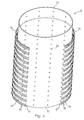
Figure 3 schematically shows a perspective view of a section of the system of walls for the inlet of gas and of the system of walls for the outlet of gas of the reactor offigure 1 , -
Figure 4 schematically shows a perspective view of a section of just the system of walls for the outlet of gas of the reactor offigure 1 , -
Figure 5 schematically shows a perspective view of a section of a system of walls for the outlet of gas from a catalytic bed according to a variant embodiment of the invention, and -
Figure 6 schematically shows a detail of a system of walls according to a further embodiment of the present invention. - With reference to the aforementioned figures, a reactor for the heterogeneous synthesis of chemical compounds is globally indicated with 1.
- The reactor 1 is particularly suited for the synthesis of ammonia from synthesis gases comprising hydrogen and nitrogen.
- The reactor 1 comprises a substantially
cylindrical shell 2 closed at the opposite ends by respective base plates, top 3 andbottom 4. The reactor 1 is also provided on thetop base plate 4 with anopening 5 for the inlet of a gaseous flow of reactant gases and on thebase plate 3 with anopening 6 for the outlet of a gaseous flow comprising the reaction products. - Inside the
shell 2 an annularcatalytic bed 7 is formed of the type with axial-radial crossing, defined at the side by respective systems of walls according to the invention, globally indicated with 8 and 9 respectively for the inlet and for the outlet of the gases from thecatalytic bed 7. The relevant characteristics of the systems ofwalls - The
catalytic bed 7 is not closed on top to allow it to be crossed axially by a portion of the flow of reactant gases and it is also delimited at the bottom by thebottom base plate 3 of the reactor 1. - In the reactor 1 shown in
figures 1 and2 , the system ofwalls 8 for the inlet of gas is arranged close to theshell 2 whereas the system ofwalls 9 for the outlet of gas is arranged centrally to the reactor 1. Between theshell 2 and the system ofwalls 8 for the inlet of gas anannular interspace 10 is therefore defined to allow thecatalytic bed 7 to be crossed radially by a portion of the gaseous flow of reactant gases. - The system of
walls 9, on the other hand, is closed on top by acover 11 not permeable to the gases, of known type. Achamber 12 is also provided, extending coaxially to thecatalytic bed 7, between the system ofwalls 9 and thecover 11, for sending the reaction products coming out from such a catalytic bed to theopening 6 for the outlet of them from the reactor 1. - The dashed
line 13 represented infigure 1 at the top end of the system ofwalls 8 for the inlet of gas, delimits the maximum level that can be reached by the catalyst inside thecatalytic bed 7, and defines, together with the systems ofwalls bottom base plate 3, the reaction volume available in the reactor 1. - In
figures 1 and2 the arrows indicate the various paths followed by the gases inside the reactor and in particular through thecatalytic bed 7. - In accordance with the present invention, the system of
walls 8 for the gas inlet as well as the system ofwalls 9 for the gas outlet, consists of two substantiallycylindrical walls annular interspace 16 between them. - More specifically (
figures 3 and4 ), thewall 14 of each of the systems ofwalls catalytic bed 7 for the lateral containment thereof and has a plurality of areas orportions 17 in the form of circumferential bands equipped with a plurality of axial slits 18 (i.e, extending parallel to the longitudinal axis of the shell 2) alternating with "full" areas orportions 19, in other words without slits, also in the form of circumferential bands. Theslits 18 are of a size such as to allow the free passage through them of the gases but not of the catalyst of thecatalytic bed 7. Regarding this, theslits 18 can have a width of between 0.3 and 2.5 mm, preferably between 0.5 and 1,1 mm. - The
slits 18, according to the invention, are obtained with a machining technique chosen from among milling and water cutting . - For example, the slits are obtained with the chosen technique on the metal sheet intended to form the wall 14 (or a section thereof); said sheet is then subjected to possible finishing processes and then rolled to form the
cylindrical wall 14 or part thereof. - The
containment wall 14 is advantageously formed with a suitable thickness and material such as to have good mechanical strength during the operation of the reactor also under the effect of nitriding or other corrosion. As an example, in the case of a reactor for ammonia synthesis, thecontainment wall 14 can be formed with a thickness of between I and 10 mm, preferably between 3 and 6 mm and the material of said wall can be any material having ordinary resistance to nitriding like for example stainless steel. Regarding this, it should be noted that a and wall made in this way, although subject to the surface nitriding effects typical of ammonia synthesis, said effects weakening it over time, maintains adequate mechanical strength during normal conditions of use of the reactor 1. It should also be noted that thecontainment wall 14 can be formed with a suitable thickness so as to act as well as for containment also as a mechanical support for thecatalytic bed 7 through the respective "full"portions 19, i.e. withoutslits 8. - The
distribution wall 15 of each of thewall systems holes 21 arranged, in the example shown here, in parallel axial groups in predetermined spaced apart relationship. More specifically, theholes 21 preferably face towards the areas or portions impermeable to the gases of thecontainment wall 14 so as to avoid the direct impact of the gases with the catalyst. In the example shown in the figures, such areas or portions impermeable to the gases consist of full areas orportions 19 between theslits 18 of thewall 14. - In the case of the system of
walls 8 for the inlet of gas, the function of thewall 15 is essentially to promote the uniform distribution of the gases going into thecatalytic bed 7 as shell be described more clearly hereafter. Thewall 15 is made from a conventional material, for example stainless steel, and obtained through conventional processes with a suitable thickness according to requirements. Preferably, thedistribution wall 15 is obtained with a suitable thickness to act as a mechanical support for thecatalytic bed 7. Thedistribution wall 15 can also be equipped with spacers (not shown) to stably maintain the spaced relationship with thecontainment wall 14 under the effect of mechanical or thermal stresses during the operation of the reactor 1. - Preferably, each of the
aforementioned walls walls - As mentioned previously, the reactor 1 comprises a system of
walls 8 for the inlet of the gases into thecatalytic bed 7 and a system ofwalls 9 for the outlet of the gases from said catalytic bed, thewalls walls 8 for the inlet of gas, thedistribution wall 15 is arranged outside (going from the axis of the reactor towards the shell) with respect to thecontainment wall 14 of saidsystem 8 of walls and forms with theshell 2 theinterspace 10. In this way, the gases that cross theannular interspace 10 pass through theholes 21 of thedistribution wall 15 and expand in theinterspace 16 between thewalls catalytic bed 7 after having crossed theslits 18 of thewall 14 in contact with the catalyst. - On the other hand, in the system of
walls 9 for the outlet of gas, thewall 15 is further in with respect to thecontainment wall 14. Therefore, the gases that radially cross saidcatalytic bed 7 come out from it by crossing theslits 18 of thewall 14 of thesystem 9 of walls and then, passing through theinterspace 16, theholes 21 of thewall 15, to be collected in thechamber 12 and from here conveyed towards theoutlet opening 6 of the reactor 1. -
Figure 5 shows a system of walls for catalytic beds of synthesis reactors according to a variant embodiment of the invention, said system being globally indicated with 50. The elements of the system ofwalls 50 that are structurally or functionally equivalent to corresponding elements of the systems ofwalls - The system of
walls 50 shown infigure 5 (preferably obtained by milling) comprises acontainment wall 14 and a substantiallycylindrical wall 15, coaxial and spaced apart so as to form anannular interspace 16 between them. In thecontainment wall 14 it is possible to distinguish a plurality ofslits 52 with a shorter arch, a plurality ofslits 53 with a longer arch andportions - The system of
walls 50 is suitable in particular for being applied onto the outlet side of a catalytic bed crossed by the gases with radial or axial-radial motion since thewall 15 is arranged inside thecontainment wall 14. Of course, by inverting the arrangement of thewalls walls 50 described above can also be applied to the gas inlet side into the catalytic bed. -
Figure 6 schematically shows an alternative form and arrangement of slits on thecontainment walls 14 of wall systems according to the invention. In particular,figure 6 shows a plurality ofslits 60 arranged axially and each being substantially coil-shaped. Said coil-shaped form is obtainable with water cutting or electro-erosion. Such a coil-shaped arrangement of slits advantageously offers a larger surface available for the crossing of the gases for the same mechanical strength of saidcontainment wall 14. - Advantageously, the
containment wall 14 has slightly flared and/or longer slits on one side as a result of the milling or water cutting processing procedure. In this case, thewall 14 is arranged with the surface having the longer and/or flared slits in direct contact with thecatalytic bed 7. This further expedient reduces the obstruction of the slits themselves, facilitating the expulsion of possible catalyst grains or parts. - Of course, a man skilled in the art can bring numerous modifications and variants to the system of walls and to the reactor described above, all of which are covered by the scope of protection of the following claims.
Claims (11)
- System of walls (8; 9; 50) for catalytic beds of chemical reactors (1) characterised in that it comprises at least one containment wall (14) of a catalytic bed (7), intended for direct contact with the same, said wall (14) having a plurality of gas-permeable portions (17) and a plurality of gas-impermeable portions (19; 54; 55), each of said gas-permeable portions (17) being equipped with a plurality of slits (18; 52, 53; 60; 70) having a size such as to allow the free passage of the synthesis gases but avoid the passage of the catalyst through them, wherein said containment wall (14) is equipped with slits (18; 52, 53; 60; 70) being more ample, in the longitudinal direction, on a side intended for direct contact with the catalyst with respect to the amplitude of the slits on an opposite side of the containment wall, said slits being obtainable with a milling process wherein a milling disc is used, in such a way that the side of the containment wall in which the slits have greater length corresponds to the milling cutter entrance side while the opposite side of the containment wall corresponds to the milling cutter exit side.
- System of walls (8; 9; 50) for catalytic beds of chemical reactors (1) characterised in that it comprises at least one containment wall (14) of a catalytic bed (7), intended for direct contact with the same, said wall (14) having a plurality of gas-permeable portions (17) and a plurality of gas-impermeable portions (19; 54; 55), each of said gas-permeable portions (17) being equipped with a plurality of slits (18; 52, 53; 60; 70) having a size such as to allow the free passage of the synthesis gases but avoid the passage of the catalyst through them, wherein said containment wall (14) is equipped with slits (18; 52, 53; 60; 70) which are flared in the width direction and obtainable with a water cutting process.
- System (8; 9; 50) of walls according to any one of the previous claims, characterised in that said containment wall (14) consists of a plurality of modules in which each module comprises said portions (17) permeable to the gases and/or said portions (19; 54, 55) impermeable to the gases.
- System (8; 9; 50) of walls according to any one of the previous claims, characterised in that it comprises furthermore a distribution wall (15) equipped with gas-permeable portions (21) arranged in spaced relationship with said containment wall (14) so as to create an interspace (16) with it.
- System (8; 9; 50) of walls according to claim 4, characterised in that said gas-permeable portions of the distribution wall (15) consist of a plurality of holes (21) made in said wall (15) and facing towards said portions (19; 54, 55) impermeable to the gases of the containment wall (14) of said catalytic bed (7).
- System (8; 9; 50) of walls according to any one of the previous claims, characterised in that said slits (60, 70) are S-shaped.
- System (8; 9; 50) of walls according to any one of the previous claims, characterised in that said slits (18) have a width of between 0.3 and 2.5 mm, preferably between 0.5 and 1.1 mm.
- Reactor (1) for the heterogeneous synthesis of chemical compounds comprising a shell (2) closed at the opposite ends by respective base plates (3, 4), an opening (5) for the inlet of synthesis gas, an opening (6) for the outlet of the reaction products, at least one catalytic bed (7) and at least one system (8, 9, 50) of walls according to any one of the previous claims for the containment of said at least one catalytic bed (7).
- Reactor (1) according to claim 8 and comprising a system of walls (8; 9; 50) according to claim 1 or 2, characterised in that said containment wall (14) of the catalytic bed is arranged so that the side with flared or longer slits is in contact with the catalytic bed.
- Process for making a containment wall (14) of a catalytic bed (7) for a chemical reactor according to claim 1, comprising the step of machining a flat metal sheet intended to form said wall (14) or a section thereof, and comprising a milling working method, thus obtaining of a plurality of slits on said sheet, said slits having a size such as to allow free passage of the gases but avoid passage of the catalyst through them, wherein the milling is carried out with control of the milling cutter or plurality of cutters, with obtainment of slits being more extended, in the longitudinal direction of the cut, on the milling cutter entrance side with respect to the milling cutter exit side.
- Process for making a containment wall (14) of a catalytic bed (7) for a chemical reactor according to claim 2, comprising the step of machining a flat metal sheet intended to form said wall (14) or a section thereof, , wherein said sheet is subjected to water cutting processing with obtainment of flared slits, said slits having a size such as to allow free passage of the gases but avoid passage of the catalyst through them.
Priority Applications (1)
| Application Number | Priority Date | Filing Date | Title |
|---|---|---|---|
| EP20080773755 EP2167226B1 (en) | 2007-07-04 | 2008-06-30 | Wall system for catalytic beds of synthesis reactors and relative production process |
Applications Claiming Priority (3)
| Application Number | Priority Date | Filing Date | Title |
|---|---|---|---|
| EP20070013091 EP2014356A1 (en) | 2007-07-04 | 2007-07-04 | Wall system for catalytic beds of synthesis reactors and relative manufacturing process |
| PCT/EP2008/005312 WO2009003663A1 (en) | 2007-07-04 | 2008-06-30 | Wall system for catalytic beds of synthesis reactors and relative production process |
| EP20080773755 EP2167226B1 (en) | 2007-07-04 | 2008-06-30 | Wall system for catalytic beds of synthesis reactors and relative production process |
Publications (2)
| Publication Number | Publication Date |
|---|---|
| EP2167226A1 EP2167226A1 (en) | 2010-03-31 |
| EP2167226B1 true EP2167226B1 (en) | 2011-03-16 |
Family
ID=38738944
Family Applications (2)
| Application Number | Title | Priority Date | Filing Date |
|---|---|---|---|
| EP20070013091 Withdrawn EP2014356A1 (en) | 2007-07-04 | 2007-07-04 | Wall system for catalytic beds of synthesis reactors and relative manufacturing process |
| EP20080773755 Active EP2167226B1 (en) | 2007-07-04 | 2008-06-30 | Wall system for catalytic beds of synthesis reactors and relative production process |
Family Applications Before (1)
| Application Number | Title | Priority Date | Filing Date |
|---|---|---|---|
| EP20070013091 Withdrawn EP2014356A1 (en) | 2007-07-04 | 2007-07-04 | Wall system for catalytic beds of synthesis reactors and relative manufacturing process |
Country Status (16)
| Country | Link |
|---|---|
| US (2) | US8435458B2 (en) |
| EP (2) | EP2014356A1 (en) |
| CN (1) | CN101730581B (en) |
| AR (1) | AR067418A1 (en) |
| AT (1) | ATE501785T1 (en) |
| AU (1) | AU2008271605B2 (en) |
| BR (1) | BRPI0812901B1 (en) |
| CA (1) | CA2691435C (en) |
| CL (1) | CL2008001947A1 (en) |
| DE (1) | DE602008005588D1 (en) |
| DK (1) | DK2167226T3 (en) |
| EG (1) | EG26977A (en) |
| MY (1) | MY146812A (en) |
| RU (1) | RU2462299C2 (en) |
| UA (1) | UA96645C2 (en) |
| WO (1) | WO2009003663A1 (en) |
Cited By (2)
| Publication number | Priority date | Publication date | Assignee | Title |
|---|---|---|---|---|
| US10329159B2 (en) | 2016-06-21 | 2019-06-25 | Haldor Topsoe A/S | Axial-radial flow converter |
| WO2019121951A1 (en) | 2017-12-20 | 2019-06-27 | Haldor Topsøe A/S | Adiabatic axial flow converter |
Families Citing this family (14)
| Publication number | Priority date | Publication date | Assignee | Title |
|---|---|---|---|---|
| EP2374757A1 (en) * | 2010-04-09 | 2011-10-12 | Ammonia Casale S.A. | Method for modifying a hot wall ammonia reactor with vessel having a partial opening |
| FR2993201B1 (en) * | 2012-07-10 | 2014-08-08 | Total Raffinage Marketing | METHOD OF MAKING AN EROSION COATING ON AN INTERNAL WALL OF AN FCC UNIT ENCLOSURE AND ANCHORING STRUCTURE FOR CARRYING OUT THIS COATING. |
| EP2745901A1 (en) | 2012-12-19 | 2014-06-25 | Urea Casale SA | Method for transforming a prilling tower, in particular in a plant for the synthesis of urea |
| EP2759338A1 (en) | 2013-01-29 | 2014-07-30 | Ammonia Casale S.A. | Adiabatic multi-bed catalytic converter with inter-bed cooling |
| FR3015910B1 (en) * | 2013-12-26 | 2016-12-09 | Abdol Hossein Naderi | CATALYTIC REACTOR WITH RADIAL FLUX HAVING AN INTERNAL COLLECTOR SYSTEM |
| EP2957339A1 (en) | 2014-06-17 | 2015-12-23 | Casale SA | Radial flow horizontal catalytic reactor |
| US10076739B1 (en) | 2014-07-22 | 2018-09-18 | Precision Combustion, Inc. | Chemical reactor for use with overly reactive chemicals |
| EP3219384A1 (en) | 2016-03-16 | 2017-09-20 | Casale SA | Walls for catalytic beds of radial- or axial-flow reactors |
| BR112019005684A2 (en) | 2016-09-23 | 2019-06-11 | Casale S A | catalytic axial-radial flow chemical reactor with two catalyst layers |
| CA3061684A1 (en) | 2017-06-02 | 2018-12-06 | Casale Sa | Reactor with a catalytic bed |
| EP3646945A1 (en) | 2018-10-29 | 2020-05-06 | Casale Sa | Radial or axial-radial chemical reactor with a fine catalyst |
| CN110193326A (en) * | 2019-05-20 | 2019-09-03 | 陕西金泰氯碱化工有限公司 | A kind of gas permeable member catalyzing and synthesizing vinyl chloride optimization reaction controlling for mercury-free |
| MA59494B1 (en) * | 2020-08-13 | 2024-04-30 | Casale Sa | WALL ASSEMBLY FOR CATALYTIC BEDS OF SYNTHESIS REACTORS |
| MA63295B1 (en) | 2021-02-10 | 2025-01-31 | Casale Sa | CATALYTIC SYNTHESIS REACTOR |
Family Cites Families (11)
| Publication number | Priority date | Publication date | Assignee | Title |
|---|---|---|---|---|
| AT299981B (en) * | 1970-04-21 | 1972-07-10 | Chemie Linz Ag | Device for achieving uniform gas distribution in catalytic converter layers with radial flow in reactors for catalytic, exothermic high-pressure syntheses, preferably ammonia synthesis |
| BE792236A (en) * | 1971-12-17 | 1973-06-01 | Inst Francais Du Petrole | APPARATUS FOR THE CONVERSION OF HYDROCARBONS |
| CH670400A5 (en) * | 1986-03-13 | 1989-06-15 | Ammonia Casale Sa | |
| DE3919750A1 (en) * | 1989-06-16 | 1990-12-20 | Linde Ag | REACTOR |
| US5209908A (en) * | 1989-09-25 | 1993-05-11 | Uop | Radial flow reactor with double perforated scallops |
| FI89521C (en) * | 1991-10-04 | 1993-10-11 | Cae Investments Bv | FOERFARANDE FOER FRAMSTAELLNING AV EN SILPRODUKT OCH GENOM FOERFARANDET FRAMSTAELLD SILPRODUKT |
| AU689553B2 (en) * | 1994-03-01 | 1998-04-02 | Methanol Casale S.A. | Mixing assembly for gaseous flows at different temperatures,in particular for heterogeneous exothermic synthesis reactors |
| RU2136359C1 (en) * | 1997-07-14 | 1999-09-10 | Институт катализа им.Г.К.Борескова СО РАН | Reactor for heterogeneous exothermic synthesis |
| US20080107575A1 (en) * | 2004-12-08 | 2008-05-08 | Vetter Michael J | Apparatus and process for reacting fluid over catalyst bed |
| JP4359701B2 (en) * | 2005-08-22 | 2009-11-04 | 飛島建設株式会社 | Steel pipe pile part removal method of earth retaining wall |
| EP1818094A1 (en) * | 2006-02-13 | 2007-08-15 | Ammonia Casale S.A. | Wall system for catalytic beds of synthesis reactors |
-
2007
- 2007-07-04 EP EP20070013091 patent/EP2014356A1/en not_active Withdrawn
-
2008
- 2008-06-30 UA UAA201001085A patent/UA96645C2/en unknown
- 2008-06-30 CA CA2691435A patent/CA2691435C/en active Active
- 2008-06-30 US US12/667,315 patent/US8435458B2/en active Active
- 2008-06-30 AT AT08773755T patent/ATE501785T1/en not_active IP Right Cessation
- 2008-06-30 DK DK08773755T patent/DK2167226T3/en active
- 2008-06-30 DE DE200860005588 patent/DE602008005588D1/en active Active
- 2008-06-30 AU AU2008271605A patent/AU2008271605B2/en active Active
- 2008-06-30 WO PCT/EP2008/005312 patent/WO2009003663A1/en not_active Ceased
- 2008-06-30 BR BRPI0812901-0A patent/BRPI0812901B1/en active IP Right Grant
- 2008-06-30 RU RU2010103323/02A patent/RU2462299C2/en active
- 2008-06-30 EP EP20080773755 patent/EP2167226B1/en active Active
- 2008-06-30 CN CN2008800233127A patent/CN101730581B/en active Active
- 2008-07-01 CL CL2008001947A patent/CL2008001947A1/en unknown
- 2008-07-02 MY MYPI20082441A patent/MY146812A/en unknown
- 2008-07-03 AR ARP080102892 patent/AR067418A1/en active IP Right Grant
-
2010
- 2010-01-03 EG EG2010010005A patent/EG26977A/en active
-
2013
- 2013-05-01 US US13/874,972 patent/US9138712B2/en active Active
Cited By (3)
| Publication number | Priority date | Publication date | Assignee | Title |
|---|---|---|---|---|
| US10329159B2 (en) | 2016-06-21 | 2019-06-25 | Haldor Topsoe A/S | Axial-radial flow converter |
| EP4520429A2 (en) | 2016-06-21 | 2025-03-12 | Topsoe A/S | Axial/radial flow converter |
| WO2019121951A1 (en) | 2017-12-20 | 2019-06-27 | Haldor Topsøe A/S | Adiabatic axial flow converter |
Also Published As
| Publication number | Publication date |
|---|---|
| BRPI0812901B1 (en) | 2017-07-18 |
| US9138712B2 (en) | 2015-09-22 |
| DE602008005588D1 (en) | 2011-04-28 |
| US20130233138A1 (en) | 2013-09-12 |
| US8435458B2 (en) | 2013-05-07 |
| CL2008001947A1 (en) | 2009-01-09 |
| EP2014356A1 (en) | 2009-01-14 |
| AU2008271605A1 (en) | 2009-01-08 |
| DK2167226T3 (en) | 2011-06-14 |
| EP2167226A1 (en) | 2010-03-31 |
| CA2691435C (en) | 2016-03-22 |
| AR067418A1 (en) | 2009-10-07 |
| BRPI0812901A2 (en) | 2014-12-09 |
| UA96645C2 (en) | 2011-11-25 |
| RU2462299C2 (en) | 2012-09-27 |
| US20100278701A1 (en) | 2010-11-04 |
| CA2691435A1 (en) | 2009-01-08 |
| AU2008271605B2 (en) | 2011-07-28 |
| RU2010103323A (en) | 2011-08-10 |
| ATE501785T1 (en) | 2011-04-15 |
| EG26977A (en) | 2015-03-01 |
| MY146812A (en) | 2012-09-28 |
| CN101730581A (en) | 2010-06-09 |
| CN101730581B (en) | 2013-11-13 |
| WO2009003663A1 (en) | 2009-01-08 |
Similar Documents
| Publication | Publication Date | Title |
|---|---|---|
| EP2167226B1 (en) | Wall system for catalytic beds of synthesis reactors and relative production process | |
| EP1993718B1 (en) | Wall system for catalytic beds of synthesis reactors | |
| EP0073150B1 (en) | Catalyst devices | |
| WO2016133984A1 (en) | Catalyst support grid | |
| US7459132B2 (en) | Apparatus for dehydrogenation of ethylbenzene to styrene and method of retrofitting the apparatus | |
| US7109382B2 (en) | Method for the production of formaldehyde | |
| EP4532095B1 (en) | Catalyst support system for ammonia oxidation burners | |
| EP0846653B1 (en) | High efficiency catalytic carbon monoxide conversion process | |
| EP4291325B1 (en) | Catalytic synthesis reactor | |
| MX2008009845A (en) | Wall system for catalytic beds of synthesis reactors |
Legal Events
| Date | Code | Title | Description |
|---|---|---|---|
| PUAI | Public reference made under article 153(3) epc to a published international application that has entered the european phase |
Free format text: ORIGINAL CODE: 0009012 |
|
| 17P | Request for examination filed |
Effective date: 20091217 |
|
| AK | Designated contracting states |
Kind code of ref document: A1 Designated state(s): AT BE BG CH CY CZ DE DK EE ES FI FR GB GR HR HU IE IS IT LI LT LU LV MC MT NL NO PL PT RO SE SI SK TR |
|
| AX | Request for extension of the european patent |
Extension state: AL BA MK RS |
|
| 17Q | First examination report despatched |
Effective date: 20100518 |
|
| GRAP | Despatch of communication of intention to grant a patent |
Free format text: ORIGINAL CODE: EPIDOSNIGR1 |
|
| DAX | Request for extension of the european patent (deleted) | ||
| GRAS | Grant fee paid |
Free format text: ORIGINAL CODE: EPIDOSNIGR3 |
|
| GRAA | (expected) grant |
Free format text: ORIGINAL CODE: 0009210 |
|
| AK | Designated contracting states |
Kind code of ref document: B1 Designated state(s): AT BE BG CH CY CZ DE DK EE ES FI FR GB GR HR HU IE IS IT LI LT LU LV MC MT NL NO PL PT RO SE SI SK TR |
|
| REG | Reference to a national code |
Ref country code: GB Ref legal event code: FG4D |
|
| REG | Reference to a national code |
Ref country code: CH Ref legal event code: EP |
|
| REG | Reference to a national code |
Ref country code: IE Ref legal event code: FG4D |
|
| REF | Corresponds to: |
Ref document number: 602008005588 Country of ref document: DE Date of ref document: 20110428 Kind code of ref document: P |
|
| REG | Reference to a national code |
Ref country code: DE Ref legal event code: R096 Ref document number: 602008005588 Country of ref document: DE Effective date: 20110428 |
|
| REG | Reference to a national code |
Ref country code: DK Ref legal event code: T3 Ref country code: RO Ref legal event code: EPE |
|
| REG | Reference to a national code |
Ref country code: NL Ref legal event code: VDEP Effective date: 20110316 |
|
| PG25 | Lapsed in a contracting state [announced via postgrant information from national office to epo] |
Ref country code: SE Free format text: LAPSE BECAUSE OF FAILURE TO SUBMIT A TRANSLATION OF THE DESCRIPTION OR TO PAY THE FEE WITHIN THE PRESCRIBED TIME-LIMIT Effective date: 20110316 Ref country code: LV Free format text: LAPSE BECAUSE OF FAILURE TO SUBMIT A TRANSLATION OF THE DESCRIPTION OR TO PAY THE FEE WITHIN THE PRESCRIBED TIME-LIMIT Effective date: 20110316 Ref country code: NO Free format text: LAPSE BECAUSE OF FAILURE TO SUBMIT A TRANSLATION OF THE DESCRIPTION OR TO PAY THE FEE WITHIN THE PRESCRIBED TIME-LIMIT Effective date: 20110616 Ref country code: LT Free format text: LAPSE BECAUSE OF FAILURE TO SUBMIT A TRANSLATION OF THE DESCRIPTION OR TO PAY THE FEE WITHIN THE PRESCRIBED TIME-LIMIT Effective date: 20110316 Ref country code: ES Free format text: LAPSE BECAUSE OF FAILURE TO SUBMIT A TRANSLATION OF THE DESCRIPTION OR TO PAY THE FEE WITHIN THE PRESCRIBED TIME-LIMIT Effective date: 20110627 Ref country code: GR Free format text: LAPSE BECAUSE OF FAILURE TO SUBMIT A TRANSLATION OF THE DESCRIPTION OR TO PAY THE FEE WITHIN THE PRESCRIBED TIME-LIMIT Effective date: 20110617 Ref country code: HR Free format text: LAPSE BECAUSE OF FAILURE TO SUBMIT A TRANSLATION OF THE DESCRIPTION OR TO PAY THE FEE WITHIN THE PRESCRIBED TIME-LIMIT Effective date: 20110316 |
|
| LTIE | Lt: invalidation of european patent or patent extension |
Effective date: 20110316 |
|
| PG25 | Lapsed in a contracting state [announced via postgrant information from national office to epo] |
Ref country code: FI Free format text: LAPSE BECAUSE OF FAILURE TO SUBMIT A TRANSLATION OF THE DESCRIPTION OR TO PAY THE FEE WITHIN THE PRESCRIBED TIME-LIMIT Effective date: 20110316 Ref country code: SI Free format text: LAPSE BECAUSE OF FAILURE TO SUBMIT A TRANSLATION OF THE DESCRIPTION OR TO PAY THE FEE WITHIN THE PRESCRIBED TIME-LIMIT Effective date: 20110316 Ref country code: CY Free format text: LAPSE BECAUSE OF FAILURE TO SUBMIT A TRANSLATION OF THE DESCRIPTION OR TO PAY THE FEE WITHIN THE PRESCRIBED TIME-LIMIT Effective date: 20110316 Ref country code: BG Free format text: LAPSE BECAUSE OF FAILURE TO SUBMIT A TRANSLATION OF THE DESCRIPTION OR TO PAY THE FEE WITHIN THE PRESCRIBED TIME-LIMIT Effective date: 20110616 Ref country code: AT Free format text: LAPSE BECAUSE OF FAILURE TO SUBMIT A TRANSLATION OF THE DESCRIPTION OR TO PAY THE FEE WITHIN THE PRESCRIBED TIME-LIMIT Effective date: 20110316 |
|
| PG25 | Lapsed in a contracting state [announced via postgrant information from national office to epo] |
Ref country code: BE Free format text: LAPSE BECAUSE OF FAILURE TO SUBMIT A TRANSLATION OF THE DESCRIPTION OR TO PAY THE FEE WITHIN THE PRESCRIBED TIME-LIMIT Effective date: 20110316 |
|
| PG25 | Lapsed in a contracting state [announced via postgrant information from national office to epo] |
Ref country code: PT Free format text: LAPSE BECAUSE OF FAILURE TO SUBMIT A TRANSLATION OF THE DESCRIPTION OR TO PAY THE FEE WITHIN THE PRESCRIBED TIME-LIMIT Effective date: 20110718 Ref country code: EE Free format text: LAPSE BECAUSE OF FAILURE TO SUBMIT A TRANSLATION OF THE DESCRIPTION OR TO PAY THE FEE WITHIN THE PRESCRIBED TIME-LIMIT Effective date: 20110316 |
|
| PG25 | Lapsed in a contracting state [announced via postgrant information from national office to epo] |
Ref country code: IS Free format text: LAPSE BECAUSE OF FAILURE TO SUBMIT A TRANSLATION OF THE DESCRIPTION OR TO PAY THE FEE WITHIN THE PRESCRIBED TIME-LIMIT Effective date: 20110716 Ref country code: SK Free format text: LAPSE BECAUSE OF FAILURE TO SUBMIT A TRANSLATION OF THE DESCRIPTION OR TO PAY THE FEE WITHIN THE PRESCRIBED TIME-LIMIT Effective date: 20110316 Ref country code: CZ Free format text: LAPSE BECAUSE OF FAILURE TO SUBMIT A TRANSLATION OF THE DESCRIPTION OR TO PAY THE FEE WITHIN THE PRESCRIBED TIME-LIMIT Effective date: 20110316 |
|
| PG25 | Lapsed in a contracting state [announced via postgrant information from national office to epo] |
Ref country code: NL Free format text: LAPSE BECAUSE OF FAILURE TO SUBMIT A TRANSLATION OF THE DESCRIPTION OR TO PAY THE FEE WITHIN THE PRESCRIBED TIME-LIMIT Effective date: 20110316 Ref country code: MT Free format text: LAPSE BECAUSE OF FAILURE TO SUBMIT A TRANSLATION OF THE DESCRIPTION OR TO PAY THE FEE WITHIN THE PRESCRIBED TIME-LIMIT Effective date: 20110316 |
|
| PLBE | No opposition filed within time limit |
Free format text: ORIGINAL CODE: 0009261 |
|
| STAA | Information on the status of an ep patent application or granted ep patent |
Free format text: STATUS: NO OPPOSITION FILED WITHIN TIME LIMIT |
|
| 26N | No opposition filed |
Effective date: 20111219 |
|
| PG25 | Lapsed in a contracting state [announced via postgrant information from national office to epo] |
Ref country code: PL Free format text: LAPSE BECAUSE OF FAILURE TO SUBMIT A TRANSLATION OF THE DESCRIPTION OR TO PAY THE FEE WITHIN THE PRESCRIBED TIME-LIMIT Effective date: 20110316 |
|
| REG | Reference to a national code |
Ref country code: IE Ref legal event code: MM4A |
|
| REG | Reference to a national code |
Ref country code: DE Ref legal event code: R097 Ref document number: 602008005588 Country of ref document: DE Effective date: 20111219 |
|
| PG25 | Lapsed in a contracting state [announced via postgrant information from national office to epo] |
Ref country code: IE Free format text: LAPSE BECAUSE OF NON-PAYMENT OF DUE FEES Effective date: 20110630 |
|
| REG | Reference to a national code |
Ref country code: CH Ref legal event code: PL |
|
| REG | Reference to a national code |
Ref country code: CH Ref legal event code: PL |
|
| PG25 | Lapsed in a contracting state [announced via postgrant information from national office to epo] |
Ref country code: MC Free format text: LAPSE BECAUSE OF NON-PAYMENT OF DUE FEES Effective date: 20110630 Ref country code: CH Free format text: LAPSE BECAUSE OF NON-PAYMENT OF DUE FEES Effective date: 20120630 Ref country code: LI Free format text: LAPSE BECAUSE OF NON-PAYMENT OF DUE FEES Effective date: 20120630 |
|
| PG25 | Lapsed in a contracting state [announced via postgrant information from national office to epo] |
Ref country code: LU Free format text: LAPSE BECAUSE OF NON-PAYMENT OF DUE FEES Effective date: 20110630 |
|
| PG25 | Lapsed in a contracting state [announced via postgrant information from national office to epo] |
Ref country code: TR Free format text: LAPSE BECAUSE OF FAILURE TO SUBMIT A TRANSLATION OF THE DESCRIPTION OR TO PAY THE FEE WITHIN THE PRESCRIBED TIME-LIMIT Effective date: 20110316 |
|
| PG25 | Lapsed in a contracting state [announced via postgrant information from national office to epo] |
Ref country code: HU Free format text: LAPSE BECAUSE OF FAILURE TO SUBMIT A TRANSLATION OF THE DESCRIPTION OR TO PAY THE FEE WITHIN THE PRESCRIBED TIME-LIMIT Effective date: 20110316 |
|
| REG | Reference to a national code |
Ref country code: FR Ref legal event code: PLFP Year of fee payment: 9 |
|
| REG | Reference to a national code |
Ref country code: FR Ref legal event code: PLFP Year of fee payment: 10 |
|
| REG | Reference to a national code |
Ref country code: FR Ref legal event code: PLFP Year of fee payment: 11 |
|
| P01 | Opt-out of the competence of the unified patent court (upc) registered |
Effective date: 20230527 |
|
| PGFP | Annual fee paid to national office [announced via postgrant information from national office to epo] |
Ref country code: DE Payment date: 20250520 Year of fee payment: 18 |
|
| PGFP | Annual fee paid to national office [announced via postgrant information from national office to epo] |
Ref country code: GB Payment date: 20250520 Year of fee payment: 18 Ref country code: DK Payment date: 20250520 Year of fee payment: 18 |
|
| PGFP | Annual fee paid to national office [announced via postgrant information from national office to epo] |
Ref country code: IT Payment date: 20250520 Year of fee payment: 18 |
|
| PGFP | Annual fee paid to national office [announced via postgrant information from national office to epo] |
Ref country code: FR Payment date: 20250520 Year of fee payment: 18 |
|
| PGFP | Annual fee paid to national office [announced via postgrant information from national office to epo] |
Ref country code: RO Payment date: 20250616 Year of fee payment: 18 |