EP2166458A2 - Termination resistor scheme - Google Patents
Termination resistor scheme Download PDFInfo
- Publication number
- EP2166458A2 EP2166458A2 EP09169706A EP09169706A EP2166458A2 EP 2166458 A2 EP2166458 A2 EP 2166458A2 EP 09169706 A EP09169706 A EP 09169706A EP 09169706 A EP09169706 A EP 09169706A EP 2166458 A2 EP2166458 A2 EP 2166458A2
- Authority
- EP
- European Patent Office
- Prior art keywords
- bus
- circuit connectivity
- termination
- transceiver
- terminating
- Prior art date
- Legal status (The legal status is an assumption and is not a legal conclusion. Google has not performed a legal analysis and makes no representation as to the accuracy of the status listed.)
- Granted
Links
Images




Classifications
-
- G—PHYSICS
- G06—COMPUTING OR CALCULATING; COUNTING
- G06F—ELECTRIC DIGITAL DATA PROCESSING
- G06F13/00—Interconnection of, or transfer of information or other signals between, memories, input/output devices or central processing units
- G06F13/38—Information transfer, e.g. on bus
- G06F13/40—Bus structure
- G06F13/4063—Device-to-bus coupling
- G06F13/4068—Electrical coupling
- G06F13/4086—Bus impedance matching, e.g. termination
Definitions
- a communication bus such as the NMEA 2000 bus specified by the National Marine Electronics Association includes a backbone with terminating resistors at each end. Under this configuration, when it is necessary to place an instrument at a distance from other instruments on the bus, a node drop with a terminating resistor needs to be placed at a distant location or the bus needs to be run up and back from the remote location.
- a method and corresponding apparatus that terminates circuit connectivity in a bus by coupling a terminating resistance to an instrument placed at an end of the bus.
- a method and corresponding apparatus that terminates circuit connectivity in a bus by determining location of an instrument in the bus, and terminating circuit connectivity in the bus based on the location of the instrument and as a function of coupling a terminating resistance to the instrument.
- a method and corresponding apparatus that connects a transceiver to a terminating resistance and determines a state of termination of circuit connectivity in a bus as a function of sensing receive activity in the transceiver.
- an apparatus that includes a terminating resistance coupled with an instrument placed at the end of a bus, and at least one male-to-male connector arranged to establish a connection between the terminating resistance and the bus to terminate circuit connectivity in the bus.
- system may be interpreted as a system, a subsystem, apparatus, method or any combination thereof.
- the system may terminate circuit connectivity as a function of establishing a connection between the bus and the terminating resistance.
- the system may establish the connection between the bus and the terminating resistance using pin connectors.
- the connection between the bus and the terminating resistance may be established as a function of including at least one male-to-male pin between female receptacles of two otherwise mating connectors.
- the system may couple a terminating resistance to the instrument in an event the instrument is located at an end of the bus.
- the system may connect a receive output of the transceiver to an interrupt pin of a microprocessor, generate an interrupt as a function of sensing receive activity in the receive output, and determine the termination of circuit connectivity in the bus as a function of the generated interrupt.
- the system may monitor the interrupt pin to determine the state of termination of circuit connectivity in the bus.
- the system may disable the interrupt pin in an event termination of circuit connectivity in the bus is determined.
- NMEA 2000 is a combined electrical and data specification for a marine data network for communication between marine electronic devices such as depth finders, sensors and other instruments.
- Another example embodiment of the present invention relates to determining whether or not the terminating resistor has been coupled to the bus.
- Fig. 1 illustrates a perspective view of a sail vessel 100 (illustrated in U.S. Patent Application Publication 2006/0236910 , the teachings of which are incorporated by reference in its entirety).
- the sail vessel 100 may include a hull 110, a mast 120, a centerboard or keel 160, and a rudder 170.
- the hull 110, the mast 120, and the keel 160 are designed to ensure the static and dynamic stability of the sailing vessel 100.
- the sail vessel 100 may also include a control system.
- the control system may include an interface unit 144, and a control center 146, and an instrumentation center 142.
- the interface unit 144 and the control center 146 may be located on board of the sail vessel 100 and provide a means for communicating with the instrumentation center 142.
- the instrumentation center 142 is located atop the mast 120 and provides a means for mounting a plurality of masthead devices 130.
- the instrumentation center 142 may include masthead devices such as an antenna, a running light, an anchor light, or a weather device such as an Airmar WeatherStation instrument.
- a bus cable 150 such as a coaxial cable, running up the mast 120, may connect the instrumentation center 142 to the interface center 144.
- the bus cable 150 may include a bus interface for terminating circuit connectivity according to an example embodiment of the present invention.
- the bus cable 150 may run up the mast 120, in which case a backbone exists at the top of the mast for connecting the masthead devices.
- instruments such as radar may communicate with the masthead devices via ethernet and may include features for terminating circuit connectivity according to an example embodiment of the present invention.
- an Airmar WeatherStation instrument may be connected via a backbone to the radar, and instruments placed at each end of the backbone may include features for terminating circuit connectivity according to an example embodiment of the present invention.
- Fig. 2 is an example illustration of a management unit 200 that may be used with the techniques described herein.
- the components of the management unit 200 may be fully or partially placed in the instrumentation center 142, on top the mast 120, as a part of the plurality of mast head devices 130, in the control center 146, or in the interface unit 144.
- the management unit 200 may include a memory unit 215 along with a processor 205 that may be connected to various interfaces via an input/output (I/O) device interface 255.
- the memory unit 215 may be a computer-readable memory and include combinations of non-volatile memory devices.
- the memory unit 215 is configured to hold various computer-executable instructions and data structures including computer-executable instructions and data structures that implement aspects of the techniques described herein.
- the memory unit 215 may include a unit for procedures involved in determining state of circuit connectivity termination 201 according to an example embodiment of the present invention (illustrated in detail in Fig. 4 ).
- the memory unit 215 may also include an operating system 205 and be arranged to implement various conventional operating system functions including task and process scheduling, memory management, and controlled access to various devices, such as a database storage unit 235.
- the processes may include computer-executable instructions and data that are configured to implement various aspects of the techniques described herein.
- the management unit 200 may also include a network interface 245 to connect the system to a network.
- the processor 205 may include a conventional central processing unit (CPU) comprising processing circuitry that is configured to execute various instructions and manipulate data structures from the memory unit 215.
- CPU central processing unit
- the I/O device interfaces 255 may include logic to interface with various input and/or output devices, such as a keypad or mouse and with the processor 225.
- the I/O device interfaces 255 may be configured to allow signals to be transferred between the management unit 200 and other components of the system.
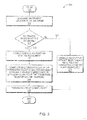
- Fig. 3 is a flow diagram of a process 300 for an example embodiment for terminating circuit connectivity in a bus.
- the process 300 starts 305 with determining the location of an instrument in the bus at 315.
- the process determines if the instrument is placed at the end of the bus at 325. If it is determined that the instrument is placed at the end of the bus at 329, a terminating resistor is coupled with the instrument at 335.
- the example embodiment connects female receptacles of the terminating resistor and the bus using at least one male-to-male connector at 345.
- the circuit connectivity is terminated at 355. If the instrument is not placed at the end of the bus at 327, the instrument is connected without a male-to-male pin 370 so that the terminator resistor is not connected and circuit connectivity is terminated 355.
- Fig. 4 is a flow diagram of a process 400 for an example embodiment for determining state of termination of circuit connectivity in a bus.
- the process 400 starts by connecting a transceiver to a terminating resistor at 415.
- the process 400 also connects a receive pin of the transceiver to an interrupt pin of a microprocessor at 425.
- the process 400 checks to determine if the receive pin of the transceiver senses receive activity at 435. Upon checking for detection of receive activity at 445, if receive activity is not detected at 447, the process continues to check to see if the receive pin of the transceiver senses receive activity 435. If receive activity is detected at 449 the process 400 generates an interrupt at 455.
- the example embodiment determines termination of circuit connectivity at 465. If termination of circuit connectivity is not determined at 477, the process 400 continues to determine termination of circuit connectivity at 465. If termination of circuit connectivity is determined at 479, the process 400 disables the interrupt pin of the microprocessor at 485, indicating that termination of circuit connectivity has been achieved.
- Fig. 5 is an example embodiment 500 of a configuration that terminates circuit connectivity.
- the bus 510 may be a part of a normal configuration of a National Marine Electronics Association (NMEA) configuration such as the NMEA 2000.
- NMEA National Marine Electronics Association
- the normal Configuration of the NMEA 2000 Bus includes a backbone that is designed to have terminating resistors at each end. Under the normal configuration, all the devices on the bus are connected to drops between the two ends of the bus 510.
- the devices on the network 520, 521, 522 may include elements such as an application layer 540, data link layer 541, network management 542, and a transceiver 543.
- an example embodiment of the present invention is arranged to attach the device 520 to the end of the bus 510 and couple the terminating resistor 530 to the device 520.
- the example embodiment 500 avoids the need for placing a node drop with terminating resistor at the distant location, or, worse yet, running the bus up and back from the remote location.
- Another example embodiment 500 may include a short bus, with an instrument on each end, each with a built in terminating resistor.
- the example embodiment 500 determines if the device 520 is located at the end of the bus 510. If the device 520 is located at the end of the bus 510, the example embodiment 500 couples a terminating resistor to the device 520.
- the example embodiment connects female receptacles of the terminating resistor and the bus interface for the terminating resistor using at least one male-to-male connector 550. Once the terminating resistor 530 and the bus interface 535 for the terminating resistor are coupled, the circuit connectivity is terminated.
- Another example embodiment 500 may use switch such as a mechanical switch or a electric(al) switch as a substitute for male-to-male connector 550 in order to couple a terminating resistor to the device 520.
- switch such as a mechanical switch or a electric(al) switch as a substitute for male-to-male connector 550 in order to couple a terminating resistor to the device 520.
- the example embodiment 500 determines if the device 520 is located at the end of the bus 510. If the device 520 is located at the end of the bus 510, the example embodiment 500 couples a terminating resistor to the device 520.
- the example embodiment connects the terminating resistor and the bus interface using at least switch. Once the terminating resistor 530 and the bus interface 535 for the terminating resistor are coupled, the circuit connectivity is terminated.
- Another example embodiment 500 may use display lamp such as an lightemitting diode in order to visually indicate a state of the termination of the devises.
- the example embodiment 500 determines if the device 520 is located at the end of the bus 510. If the device 520 is located at the end of the bus 510, the example embodiment 500 couples a terminating resistor to the device 520.
- the example embodiment indicates the state using at least display lamp such as the lightemitting diode.
- Fig. 6 is an example illustration 600 of a connection established between a bus and a terminating resistance.
- the example embodiment 600 of the present invention may accomplish the coupling of the terminating resistor 635 and the bus interface 630 using a nine pin connector 610.
- the instrument has male pins
- the bus connector 630 has female receptacles.
- the ninth pin 619A, 619B has female receptacles in both connectors. Thus, normally, there would be no connection between the two connectors. This would disconnect one end of the terminating resistor 635.
- a male-to-male pin 620 is inserted in between the two connectors 619A, 619B, such that when they are mated, pin 5 of the instrument is connected to pin 5 615A, 615B of the bus connector 630. Pin 5 of the bus connector 630 is shorted to the other side of the bus, thus connecting the terminating resistor 635 across the bus.
- the example embodiment 600 may connect a Controller Area Network (CAN) transceiver 650 across the terminating resistor 635.
- CAN Controller Area Network
- the receive pin 651 of the CAN transceiver 650 only receives activity if the resistor 635 and the bus connector 630 are coupled.
- the input of the transceiver 650 is connected to a voltage that can put the device in a very low power receive only mode, thereby saving power.
- the receive output 651 of the transceiver 650 is connected to an interrupt pin 660 on the microprocessor. Interrupts are only generated if the terminating resistor 635 is connected.
- the example embodiment 600 monitors this pin 660 initially, and disables interrupts once it has been determined whether the terminating resistor 635 is coupled to the bus 630 or not.
- the example embodiment 600 determines termination of circuit connectivity. If termination of circuit connectivity is not determined, the example embodiment 600 continues to determine termination of circuit connectivity. If termination of circuit connectivity is determined, the example embodiment 600 disables the interrupt pin 660 of the microprocessor , indicating that termination of circuit connectivity has been achieved.
- Figs. 7 illustrates the procedures involved in determining state of circuit connectivity termination according to an example embodiment of the present invention 700.
- Rsense Interrupt 1).
- the example embodiment indicates that the presence of a terminator resistor has not yet been detected.
- the value of RsenseOccurred is set to one and the indicator flag is set to zero, the example embodiment indicates that the presence of a terminator resistor has been detected.
- the example embodiment 700 increments the value of RsenseOccurred by one 740 and disables interrupt by disabling Rsence Interrupt 750.
Landscapes
- Engineering & Computer Science (AREA)
- General Engineering & Computer Science (AREA)
- Theoretical Computer Science (AREA)
- Computer Hardware Design (AREA)
- Physics & Mathematics (AREA)
- General Physics & Mathematics (AREA)
- Dc Digital Transmission (AREA)
Abstract
Description
- A communication bus such as the NMEA 2000 bus specified by the National Marine Electronics Association includes a backbone with terminating resistors at each end. Under this configuration, when it is necessary to place an instrument at a distance from other instruments on the bus, a node drop with a terminating resistor needs to be placed at a distant location or the bus needs to be run up and back from the remote location.
- It is desirable to choose to include a terminating resistor depending on the location of an instrument and select whether the terminating resistor is connected.
- According to an aspect of the present invention there is provided a method and corresponding apparatus that terminates circuit connectivity in a bus by coupling a terminating resistance to an instrument placed at an end of the bus.
- According to another aspect of the present invention there is provided a method and corresponding apparatus that terminates circuit connectivity in a bus by determining location of an instrument in the bus, and terminating circuit connectivity in the bus based on the location of the instrument and as a function of coupling a terminating resistance to the instrument.
- According to yet another aspect of the present invention there is provided a method and corresponding apparatus that connects a transceiver to a terminating resistance and determines a state of termination of circuit connectivity in a bus as a function of sensing receive activity in the transceiver.
- According to yet another aspect of the present invention there is provided an apparatus that includes a terminating resistance coupled with an instrument placed at the end of a bus, and at least one male-to-male connector arranged to establish a connection between the terminating resistance and the bus to terminate circuit connectivity in the bus.
- In the view of the foregoing, the following description illustrates example embodiments and features that may be incorporated into a system for terminating circuit connectivity in a bus and determining the state of circuit connectivity in the bus, where the term "system" may be interpreted as a system, a subsystem, apparatus, method or any combination thereof.
- The system may terminate circuit connectivity as a function of establishing a connection between the bus and the terminating resistance. The system may establish the connection between the bus and the terminating resistance using pin connectors. The connection between the bus and the terminating resistance may be established as a function of including at least one male-to-male pin between female receptacles of two otherwise mating connectors.
- The system may couple a terminating resistance to the instrument in an event the instrument is located at an end of the bus.
- The system may connect a receive output of the transceiver to an interrupt pin of a microprocessor, generate an interrupt as a function of sensing receive activity in the receive output, and determine the termination of circuit connectivity in the bus as a function of the generated interrupt. The system may monitor the interrupt pin to determine the state of termination of circuit connectivity in the bus. The system may disable the interrupt pin in an event termination of circuit connectivity in the bus is determined.
- The foregoing will be apparent from the following more particular description of example embodiments of the invention, as illustrated in the accompanying drawings in which like reference characters refer to the same parts throughout the different views. The drawings are not necessarily to scale, emphasis instead being placed upon illustrating embodiments of the present invention.
-
Fig. 1 is an illustration of a perspective view of a sailboat. -
Fig. 2 is an example illustration of a management unit that may be used with the techniques described herein. -
Fig. 3 is a flow diagram of procedures for an example embodiment for terminating circuit connectivity in a bus. -
Fig. 4 is a flow diagram of procedures for an example embodiment for determining state of termination of circuit connectivity in a bus. -
Fig. 5 is an example illustration of a bus that terminates circuit connectivity. -
Fig. 6 is an example illustration of a connection established between a bus and a terminating resistance. -
Fig. 7 is an example embodiment of the procedures involved in determining state of circuit connectivity termination. - One example embodiment of the present invention relates to coupling a terminating resistor to a bus when an instrument is located at an end of a bus such as a National Marine Electronics Association (NMEA) 2000 Controller Area Network (CAN) Bus. NMEA 2000 is a combined electrical and data specification for a marine data network for communication between marine electronic devices such as depth finders, sensors and other instruments.
- Another example embodiment of the present invention relates to determining whether or not the terminating resistor has been coupled to the bus.
-
Fig. 1 illustrates a perspective view of a sail vessel 100 (illustrated inU.S. Patent Application Publication 2006/0236910 , the teachings of which are incorporated by reference in its entirety). The sail vessel 100 may include ahull 110, amast 120, a centerboard orkeel 160, and arudder 170. Typically, thehull 110, themast 120, and thekeel 160 are designed to ensure the static and dynamic stability of the sailing vessel 100. The sail vessel 100 may also include a control system. The control system may include aninterface unit 144, and acontrol center 146, and an instrumentation center 142. Theinterface unit 144 and thecontrol center 146 may be located on board of the sail vessel 100 and provide a means for communicating with the instrumentation center 142. The instrumentation center 142 is located atop themast 120 and provides a means for mounting a plurality ofmasthead devices 130. - The instrumentation center 142 may include masthead devices such as an antenna, a running light, an anchor light, or a weather device such as an Airmar WeatherStation instrument. A bus cable 150, such as a coaxial cable, running up the
mast 120, may connect the instrumentation center 142 to theinterface center 144. The bus cable 150 may include a bus interface for terminating circuit connectivity according to an example embodiment of the present invention. - In one example embodiment, the bus cable 150 may run up the
mast 120, in which case a backbone exists at the top of the mast for connecting the masthead devices. In another example embodiment, instruments such as radar may communicate with the masthead devices via ethernet and may include features for terminating circuit connectivity according to an example embodiment of the present invention. In yet another embodiment, an Airmar WeatherStation instrument may be connected via a backbone to the radar, and instruments placed at each end of the backbone may include features for terminating circuit connectivity according to an example embodiment of the present invention. -
Fig. 2 is an example illustration of amanagement unit 200 that may be used with the techniques described herein. The components of themanagement unit 200 may be fully or partially placed in the instrumentation center 142, on top themast 120, as a part of the plurality ofmast head devices 130, in thecontrol center 146, or in theinterface unit 144. - The
management unit 200 may include amemory unit 215 along with aprocessor 205 that may be connected to various interfaces via an input/output (I/O)device interface 255. Thememory unit 215 may be a computer-readable memory and include combinations of non-volatile memory devices. Thememory unit 215 is configured to hold various computer-executable instructions and data structures including computer-executable instructions and data structures that implement aspects of the techniques described herein. - The
memory unit 215 may include a unit for procedures involved in determining state ofcircuit connectivity termination 201 according to an example embodiment of the present invention (illustrated in detail inFig. 4 ). - The
memory unit 215 may also include anoperating system 205 and be arranged to implement various conventional operating system functions including task and process scheduling, memory management, and controlled access to various devices, such as adatabase storage unit 235. The processes may include computer-executable instructions and data that are configured to implement various aspects of the techniques described herein. - The
management unit 200 may also include anetwork interface 245 to connect the system to a network. Theprocessor 205 may include a conventional central processing unit (CPU) comprising processing circuitry that is configured to execute various instructions and manipulate data structures from thememory unit 215. - The I/
O device interfaces 255 may include logic to interface with various input and/or output devices, such as a keypad or mouse and with theprocessor 225. The I/O device interfaces 255 may be configured to allow signals to be transferred between themanagement unit 200 and other components of the system. -
Fig. 3 is a flow diagram of aprocess 300 for an example embodiment for terminating circuit connectivity in a bus. Theprocess 300 starts 305 with determining the location of an instrument in the bus at 315. The process determines if the instrument is placed at the end of the bus at 325. If it is determined that the instrument is placed at the end of the bus at 329, a terminating resistor is coupled with the instrument at 335. In order to couple the terminating resistor with the instrument, the example embodiment connects female receptacles of the terminating resistor and the bus using at least one male-to-male connector at 345. Once the instrument and the bus are coupled, with or without the terminating resistor, the circuit connectivity is terminated at 355. If the instrument is not placed at the end of the bus at 327, the instrument is connected without a male-to-male pin 370 so that the terminator resistor is not connected and circuit connectivity is terminated 355. -
Fig. 4 is a flow diagram of aprocess 400 for an example embodiment for determining state of termination of circuit connectivity in a bus. Theprocess 400 starts by connecting a transceiver to a terminating resistor at 415. Theprocess 400 also connects a receive pin of the transceiver to an interrupt pin of a microprocessor at 425. Theprocess 400 checks to determine if the receive pin of the transceiver senses receive activity at 435. Upon checking for detection of receive activity at 445, if receive activity is not detected at 447, the process continues to check to see if the receive pin of the transceiver senses receiveactivity 435. If receive activity is detected at 449 theprocess 400 generates an interrupt at 455. Based on the generated interrupt, the example embodiment determines termination of circuit connectivity at 465. If termination of circuit connectivity is not determined at 477, theprocess 400 continues to determine termination of circuit connectivity at 465. If termination of circuit connectivity is determined at 479, theprocess 400 disables the interrupt pin of the microprocessor at 485, indicating that termination of circuit connectivity has been achieved. -
Fig. 5 is an example embodiment 500 of a configuration that terminates circuit connectivity. Thebus 510 may be a part of a normal configuration of a National Marine Electronics Association (NMEA) configuration such as the NMEA 2000. The normal Configuration of the NMEA 2000 Bus includes a backbone that is designed to have terminating resistors at each end. Under the normal configuration, all the devices on the bus are connected to drops between the two ends of thebus 510. The devices on thenetwork application layer 540,data link layer 541,network management 542, and atransceiver 543. However, when adevice 520 on the network needs to be located at a distance from other devices on the network, an example embodiment of the present invention is arranged to attach thedevice 520 to the end of thebus 510 and couple the terminatingresistor 530 to thedevice 520. By coupling the terminatingresistor 530 with thedevice 520, the example embodiment 500 avoids the need for placing a node drop with terminating resistor at the distant location, or, worse yet, running the bus up and back from the remote location. - Another example embodiment 500 may include a short bus, with an instrument on each end, each with a built in terminating resistor.
- The example embodiment 500 determines if the
device 520 is located at the end of thebus 510. If thedevice 520 is located at the end of thebus 510, the example embodiment 500 couples a terminating resistor to thedevice 520. - In order to couple the terminating resistor with the instrument, the example embodiment connects female receptacles of the terminating resistor and the bus interface for the terminating resistor using at least one male-to-
male connector 550. Once the terminatingresistor 530 and the bus interface 535 for the terminating resistor are coupled, the circuit connectivity is terminated. - Another example embodiment 500 may use switch such as a mechanical switch or a electric(al) switch as a substitute for male-to-
male connector 550 in order to couple a terminating resistor to thedevice 520. - The example embodiment 500 determines if the
device 520 is located at the end of thebus 510. If thedevice 520 is located at the end of thebus 510, the example embodiment 500 couples a terminating resistor to thedevice 520. - In order to couple the terminating resistor with the instrument, the example embodiment connects the terminating resistor and the bus interface using at least switch. Once the terminating
resistor 530 and the bus interface 535 for the terminating resistor are coupled, the circuit connectivity is terminated. - Another example embodiment 500 may use display lamp such as an lightemitting diode in order to visually indicate a state of the termination of the devises.
- The example embodiment 500 determines if the
device 520 is located at the end of thebus 510. If thedevice 520 is located at the end of thebus 510, the example embodiment 500 couples a terminating resistor to thedevice 520. - In order to visually indicate the state of the termination of the devises, the example embodiment indicates the state using at least display lamp such as the lightemitting diode. Once the terminating
resistor 530 and the bus interface 535 for the terminating resistor are coupled, the circuit connectivity is terminated and the display lamp lights up. -
Fig. 6 is anexample illustration 600 of a connection established between a bus and a terminating resistance. Theexample embodiment 600 of the present invention may accomplish the coupling of the terminatingresistor 635 and thebus interface 630 using a ninepin connector 610. In one example embodiment, for eight of the pins, the instrument has male pins, and thebus connector 630 has female receptacles. Theninth pin resistor 635. To connect the terminating resistor, a male-to-male pin 620 is inserted in between the twoconnectors bus connector 630. Pin 5 of thebus connector 630 is shorted to the other side of the bus, thus connecting the terminatingresistor 635 across the bus. - In order to determine state of circuit connectivity termination, the
example embodiment 600 may connect a Controller Area Network (CAN)transceiver 650 across the terminatingresistor 635. The receivepin 651 of theCAN transceiver 650 only receives activity if theresistor 635 and thebus connector 630 are coupled. - The input of the
transceiver 650 is connected to a voltage that can put the device in a very low power receive only mode, thereby saving power. The receiveoutput 651 of thetransceiver 650 is connected to an interruptpin 660 on the microprocessor. Interrupts are only generated if the terminatingresistor 635 is connected. Theexample embodiment 600 monitors thispin 660 initially, and disables interrupts once it has been determined whether the terminatingresistor 635 is coupled to thebus 630 or not. - If an interrupt is generated, based on the generated interrupt, the
example embodiment 600 determines termination of circuit connectivity. If termination of circuit connectivity is not determined, theexample embodiment 600 continues to determine termination of circuit connectivity. If termination of circuit connectivity is determined, theexample embodiment 600 disables the interruptpin 660 of the microprocessor , indicating that termination of circuit connectivity has been achieved. -
Figs. 7 illustrates the procedures involved in determining state of circuit connectivity termination according to an example embodiment of thepresent invention 700. Theexample embodiment 700 starts 701 by initializing a variable RsenseOccurred to zero 702 and setting an indicator flag on (i.e., Flag = 1) as well as a interrupt indicator variable Rsense Interrupt (Rsense Interrupt = 1). By setting the variable RsenseOccurred to zero and turning on the indicator flag, the example embodiment indicates that the presence of a terminator resistor has not yet been detected. Similarly, when the value of RsenseOccurred is set to one and the indicator flag is set to zero, the example embodiment indicates that the presence of a terminator resistor has been detected. - The
example embodiment 700 is arranged to verify 706 the status of the variable RsenseOccurred on a one secondlong interval basis 704. If the value of RsenseOccurred is zero 709, the indicator flag remains on 715 (i.e., Flag = 1), indicating that a terminating resistor has not been detected. If the value of RsenseOccurred is greater than zero 708, the example embodiment resets the value of the indicator flag to zero 720 (i.e., turns the indicator flag off) and re-enables Rsense Interrupt 730. - When an interrupt occurs 730, the
example embodiment 700 increments the value of RsenseOccurred by one 740 and disables interrupt by disabling Rsence Interrupt 750. - While this invention has been particularly shown and described with references to example embodiments thereof, it will be understood by those skilled in the art that various changes in form and details may be made therein without departing from the scope of the invention encompassed by the appended claims.
Claims (15)
- An apparatus comprising:a terminating resistance coupled with an instrument placed at the end of a bus; andconnection means arranged to establish a connection between the terminating resistance and the bus to terminate circuit connectivity in the bus.
- The apparatus of claim 1 wherein the connection means includes at least one of a male-to-male connector, a mechanical switch and an electrical switch
- The apparatus of claim 1 or claim 2 further comprising a transceiver connected to the terminating resistance, the transceiver arranged to sense receive activity to determine a state of termination of circuit connectivity.
- The apparatus of claim 3 wherein a receive output of the transceiver is arranged to connect to an interrupt pin of a microprocessor, the interrupt pin being arranged to generate an interrupt to indicate termination of circuit connectivity in the bus in an event receive activity is sensed in the transceiver.
- The apparatus of claim 4 further including a monitoring module to monitor the interrupt pin to determine the state of termination of circuit connectivity in the bus.
- The apparatus of claim 4 further including a module arranged to disable the interrupt pin in an event termination of circuit connectivity in the bus is determined.
- The apparatus of claim 4 further comprising visual indication means for indicating the state of termination of circuit connectivity in the bus.
- A method comprising terminating circuit connectivity in a bus by coupling a terminating resistance to an instrument placed at an end of the bus.
- The method of claim 8 further comprising terminating circuit connectivity by establishing a connection between the bus and the terminating resistance.
- The method of claim 8 or claim 9 further comprising establishing the connection between the bus and the terminating resistance using connection means such as a mechanical switch, an electrical switch, or pin connectors.
- The method of any of claims 8 to 10 further comprising establishing the connection between the bus and the terminating resistance by including at least one male-to-male pin between female receptacles of two otherwise mating connectors.
- The method of any of claims 8 to 11 further comprising:connecting a transceiver to the terminating resistance; and determining a state of termination of circuit connectivity in the bus by sensing receive activity in the transceiver.
- The method of claim 12 including connecting a receive output of the transceiver to an interrupt pin of a microprocessor, generating an interrupt as a function of sensing receive activity in the receive output, and determining the termination of circuit connectivity in the bus as a function of the generated interrupt.
- The method of claim 13 further including monitoring the interrupt pin to determine the state of termination of circuit connectivity in the bus.
- The method of claim 13 further including disabling the interrupt pin in an event termination of circuit connectivity in the bus is determined.
Applications Claiming Priority (1)
| Application Number | Priority Date | Filing Date | Title |
|---|---|---|---|
| US12/206,982 US8390316B2 (en) | 2008-09-09 | 2008-09-09 | Termination resistor scheme |
Publications (3)
| Publication Number | Publication Date |
|---|---|
| EP2166458A2 true EP2166458A2 (en) | 2010-03-24 |
| EP2166458A3 EP2166458A3 (en) | 2010-04-07 |
| EP2166458B1 EP2166458B1 (en) | 2013-04-03 |
Family
ID=41323499
Family Applications (1)
| Application Number | Title | Priority Date | Filing Date |
|---|---|---|---|
| EP09169706A Not-in-force EP2166458B1 (en) | 2008-09-09 | 2009-09-08 | Termination resistor scheme |
Country Status (2)
| Country | Link |
|---|---|
| US (1) | US8390316B2 (en) |
| EP (1) | EP2166458B1 (en) |
Cited By (1)
| Publication number | Priority date | Publication date | Assignee | Title |
|---|---|---|---|---|
| WO2021249997A1 (en) | 2020-06-08 | 2021-12-16 | Webasto SE | Control system for a bus system having at least two transmission lines |
Families Citing this family (2)
| Publication number | Priority date | Publication date | Assignee | Title |
|---|---|---|---|---|
| US8597054B2 (en) * | 2011-03-07 | 2013-12-03 | Schneider Electric It Corporation | CAN bus automatic line termination |
| US11068433B2 (en) * | 2018-10-18 | 2021-07-20 | Texas Instruments Incorporated | Serial bus repeater with low power state detection |
Citations (1)
| Publication number | Priority date | Publication date | Assignee | Title |
|---|---|---|---|---|
| US20060236910A1 (en) | 2005-04-20 | 2006-10-26 | Aimar Technology Corporation | Masthead control system |
Family Cites Families (22)
| Publication number | Priority date | Publication date | Assignee | Title |
|---|---|---|---|---|
| US5199906A (en) | 1991-02-11 | 1993-04-06 | Trusty Industrial Co., Ltd. | Electrical connector |
| JP3399630B2 (en) * | 1993-09-27 | 2003-04-21 | 株式会社日立製作所 | Bus system |
| JP2882266B2 (en) * | 1993-12-28 | 1999-04-12 | 株式会社日立製作所 | Signal transmission device and circuit block |
| IT1274537B (en) * | 1994-05-20 | 1997-07-17 | Fujitsu Ltd | Electronic circuit apparatus for transmitting signals via a bus and semiconductor device for generating a predetermined stable voltage |
| JP3407469B2 (en) * | 1995-04-17 | 2003-05-19 | 株式会社日立製作所 | Information processing device |
| US6744352B2 (en) * | 1995-11-09 | 2004-06-01 | Vehicle Enhancement Systems, Inc. | System, apparatus and methods for data communication between vehicle and remote data communication terminal, between portions of vehicle and other portions of vehicle, between two or more vehicles, and between vehicle and communications network |
| US6026456A (en) * | 1995-12-15 | 2000-02-15 | Intel Corporation | System utilizing distributed on-chip termination |
| US6291770B1 (en) * | 1999-05-14 | 2001-09-18 | Leoni Wiring Systems, Inc. | Wiring system and method therefor |
| US6308232B1 (en) * | 1999-09-01 | 2001-10-23 | Rambus Inc. | Electronically moveable terminator and method for using same in a memory system |
| US6249142B1 (en) * | 1999-12-20 | 2001-06-19 | Intel Corporation | Dynamically terminated bus |
| US6441595B1 (en) | 2000-10-20 | 2002-08-27 | Sun Microsystems, Inc. | Universal compact PCI pull-up/termination IC |
| US6587765B1 (en) * | 2001-06-04 | 2003-07-01 | Teleflex Incorporated | Electronic control system for marine vessels |
| JP3821678B2 (en) * | 2001-09-06 | 2006-09-13 | エルピーダメモリ株式会社 | Memory device |
| US6754132B2 (en) * | 2001-10-19 | 2004-06-22 | Samsung Electronics Co., Ltd. | Devices and methods for controlling active termination resistors in a memory system |
| KR100471162B1 (en) * | 2002-02-27 | 2005-03-08 | 삼성전자주식회사 | High speed memory system |
| DE10261386A1 (en) | 2002-12-30 | 2004-07-08 | Robert Bosch Gmbh | Device for terminating two-wire lines |
| US7029312B2 (en) | 2003-04-18 | 2006-04-18 | Oops-Oops, Inc. | Double male two-prong electrical connector apparatus |
| US7068064B1 (en) | 2003-05-12 | 2006-06-27 | Pericom Semiconductor Corp. | Memory module with dynamic termination using bus switches timed by memory clock and chip select |
| US7336098B2 (en) * | 2004-06-30 | 2008-02-26 | Intel Corporation | High speed memory modules utilizing on-pin capacitors |
| KR100691583B1 (en) * | 2004-12-31 | 2007-03-09 | 학교법인 포항공과대학교 | Multi-drop bus structure memory system with multiple termination resistors |
| DE102005025573A1 (en) * | 2005-06-03 | 2006-12-07 | Ellenberger & Poensgen Gmbh | Multiplexing system for boats or caravans |
| US20070103835A1 (en) * | 2005-10-17 | 2007-05-10 | Sorenson Richard W | Remote power management and monitoring system with remote circuit breaker control |
-
2008
- 2008-09-09 US US12/206,982 patent/US8390316B2/en not_active Expired - Fee Related
-
2009
- 2009-09-08 EP EP09169706A patent/EP2166458B1/en not_active Not-in-force
Patent Citations (1)
| Publication number | Priority date | Publication date | Assignee | Title |
|---|---|---|---|---|
| US20060236910A1 (en) | 2005-04-20 | 2006-10-26 | Aimar Technology Corporation | Masthead control system |
Cited By (2)
| Publication number | Priority date | Publication date | Assignee | Title |
|---|---|---|---|---|
| WO2021249997A1 (en) | 2020-06-08 | 2021-12-16 | Webasto SE | Control system for a bus system having at least two transmission lines |
| EP4147422A1 (en) | 2020-06-08 | 2023-03-15 | Webasto SE | Control system for a bus system having at least two transmission lines |
Also Published As
| Publication number | Publication date |
|---|---|
| US8390316B2 (en) | 2013-03-05 |
| US20100060314A1 (en) | 2010-03-11 |
| EP2166458A3 (en) | 2010-04-07 |
| EP2166458B1 (en) | 2013-04-03 |
Similar Documents
| Publication | Publication Date | Title |
|---|---|---|
| US8281048B2 (en) | Information processing apparatus and method for detecting a type of apparatus connected to a connector thereof | |
| US7558975B2 (en) | Method and apparatus for remote device control using control signals superimposed over ethernet | |
| US9099816B2 (en) | Connection device for detecting connection status, electrical connection assembly, and electronic apparatus | |
| EP2166458B1 (en) | Termination resistor scheme | |
| US20130049767A1 (en) | High speed data bus tester | |
| EP3133701B1 (en) | Integrated input/output connector | |
| US20100064066A1 (en) | KVM switch system and interface adapter for detecting interface of computer | |
| EP3598596A1 (en) | Temperature sensor for a cable head for a ring main unit | |
| CN101086508B (en) | Detection equipment, connector thereof and detection method thereof | |
| US20240329701A1 (en) | Communication system for display card and power supply | |
| CN212364542U (en) | Automatic detection circuit and automatic detection device of unmanned ship | |
| CN105449402A (en) | Connector, method for using same and electronic device equipped with same | |
| CN212874987U (en) | Multimode multi-frequency comprehensive communication cable | |
| EP3849029B1 (en) | Electrical mating systems | |
| US9152192B2 (en) | Power supply and power cord for max power setting | |
| CN211627787U (en) | FPC circuit open/short circuit detection circuit, device and system | |
| CN210573761U (en) | Interface conversion circuit and signal detection device | |
| US20240204464A1 (en) | Monitoring the position of an electrical connector | |
| KR20210120770A (en) | Digital welding machine for recognizing automatically type of feeder | |
| JP3144176U (en) | System power management card and computer motherboard incorporating the card | |
| CN220829559U (en) | Test device | |
| CN222996604U (en) | Type C and DP ultra-clear audio/video bidirectional converter | |
| CN221718757U (en) | Electric water wing plate | |
| CN113938225B (en) | Multi-channel antenna comprehensive index test system | |
| KR101016896B1 (en) | Connector of hall sensor module with parameter setting port of integrated circuit device |
Legal Events
| Date | Code | Title | Description |
|---|---|---|---|
| PUAI | Public reference made under article 153(3) epc to a published international application that has entered the european phase |
Free format text: ORIGINAL CODE: 0009012 |
|
| PUAL | Search report despatched |
Free format text: ORIGINAL CODE: 0009013 |
|
| AK | Designated contracting states |
Kind code of ref document: A2 Designated state(s): AT BE BG CH CY CZ DE DK EE ES FI FR GB GR HR HU IE IS IT LI LT LU LV MC MK MT NL NO PL PT RO SE SI SK SM TR |
|
| AX | Request for extension of the european patent |
Extension state: AL BA RS |
|
| AK | Designated contracting states |
Kind code of ref document: A3 Designated state(s): AT BE BG CH CY CZ DE DK EE ES FI FR GB GR HR HU IE IS IT LI LT LU LV MC MK MT NL NO PL PT RO SE SI SK SM TR |
|
| AX | Request for extension of the european patent |
Extension state: AL BA RS |
|
| 17P | Request for examination filed |
Effective date: 20100908 |
|
| 17Q | First examination report despatched |
Effective date: 20101006 |
|
| GRAP | Despatch of communication of intention to grant a patent |
Free format text: ORIGINAL CODE: EPIDOSNIGR1 |
|
| GRAS | Grant fee paid |
Free format text: ORIGINAL CODE: EPIDOSNIGR3 |
|
| GRAA | (expected) grant |
Free format text: ORIGINAL CODE: 0009210 |
|
| AK | Designated contracting states |
Kind code of ref document: B1 Designated state(s): AT BE BG CH CY CZ DE DK EE ES FI FR GB GR HR HU IE IS IT LI LT LU LV MC MK MT NL NO PL PT RO SE SI SK SM TR |
|
| RAP1 | Party data changed (applicant data changed or rights of an application transferred) |
Owner name: FURUNO ELECTRIC COMPANY, LIMITED |
|
| REG | Reference to a national code |
Ref country code: GB Ref legal event code: FG4D |
|
| REG | Reference to a national code |
Ref country code: CH Ref legal event code: EP Ref country code: AT Ref legal event code: REF Ref document number: 605105 Country of ref document: AT Kind code of ref document: T Effective date: 20130415 |
|
| REG | Reference to a national code |
Ref country code: IE Ref legal event code: FG4D |
|
| REG | Reference to a national code |
Ref country code: DE Ref legal event code: R096 Ref document number: 602009014594 Country of ref document: DE Effective date: 20130529 |
|
| REG | Reference to a national code |
Ref country code: DE Ref legal event code: R082 Ref document number: 602009014594 Country of ref document: DE Representative=s name: WAECHTERSHAEUSER & HARTZ PATENTANWALTSPARTNERS, DE |
|
| REG | Reference to a national code |
Ref country code: DE Ref legal event code: R082 Ref document number: 602009014594 Country of ref document: DE Representative=s name: WAECHTERSHAEUSER & HARTZ PATENTANWALTSPARTNERS, DE |
|
| REG | Reference to a national code |
Ref country code: AT Ref legal event code: MK05 Ref document number: 605105 Country of ref document: AT Kind code of ref document: T Effective date: 20130403 |
|
| PG25 | Lapsed in a contracting state [announced via postgrant information from national office to epo] |
Ref country code: SI Free format text: LAPSE BECAUSE OF FAILURE TO SUBMIT A TRANSLATION OF THE DESCRIPTION OR TO PAY THE FEE WITHIN THE PRESCRIBED TIME-LIMIT Effective date: 20130403 |
|
| REG | Reference to a national code |
Ref country code: NL Ref legal event code: VDEP Effective date: 20130403 |
|
| REG | Reference to a national code |
Ref country code: LT Ref legal event code: MG4D |
|
| PG25 | Lapsed in a contracting state [announced via postgrant information from national office to epo] |
Ref country code: PT Free format text: LAPSE BECAUSE OF FAILURE TO SUBMIT A TRANSLATION OF THE DESCRIPTION OR TO PAY THE FEE WITHIN THE PRESCRIBED TIME-LIMIT Effective date: 20130805 Ref country code: SE Free format text: LAPSE BECAUSE OF FAILURE TO SUBMIT A TRANSLATION OF THE DESCRIPTION OR TO PAY THE FEE WITHIN THE PRESCRIBED TIME-LIMIT Effective date: 20130403 Ref country code: ES Free format text: LAPSE BECAUSE OF FAILURE TO SUBMIT A TRANSLATION OF THE DESCRIPTION OR TO PAY THE FEE WITHIN THE PRESCRIBED TIME-LIMIT Effective date: 20130714 Ref country code: NO Free format text: LAPSE BECAUSE OF FAILURE TO SUBMIT A TRANSLATION OF THE DESCRIPTION OR TO PAY THE FEE WITHIN THE PRESCRIBED TIME-LIMIT Effective date: 20130703 Ref country code: BE Free format text: LAPSE BECAUSE OF FAILURE TO SUBMIT A TRANSLATION OF THE DESCRIPTION OR TO PAY THE FEE WITHIN THE PRESCRIBED TIME-LIMIT Effective date: 20130403 Ref country code: FI Free format text: LAPSE BECAUSE OF FAILURE TO SUBMIT A TRANSLATION OF THE DESCRIPTION OR TO PAY THE FEE WITHIN THE PRESCRIBED TIME-LIMIT Effective date: 20130403 Ref country code: LT Free format text: LAPSE BECAUSE OF FAILURE TO SUBMIT A TRANSLATION OF THE DESCRIPTION OR TO PAY THE FEE WITHIN THE PRESCRIBED TIME-LIMIT Effective date: 20130403 Ref country code: AT Free format text: LAPSE BECAUSE OF FAILURE TO SUBMIT A TRANSLATION OF THE DESCRIPTION OR TO PAY THE FEE WITHIN THE PRESCRIBED TIME-LIMIT Effective date: 20130403 Ref country code: NL Free format text: LAPSE BECAUSE OF FAILURE TO SUBMIT A TRANSLATION OF THE DESCRIPTION OR TO PAY THE FEE WITHIN THE PRESCRIBED TIME-LIMIT Effective date: 20130403 Ref country code: GR Free format text: LAPSE BECAUSE OF FAILURE TO SUBMIT A TRANSLATION OF THE DESCRIPTION OR TO PAY THE FEE WITHIN THE PRESCRIBED TIME-LIMIT Effective date: 20130704 Ref country code: IS Free format text: LAPSE BECAUSE OF FAILURE TO SUBMIT A TRANSLATION OF THE DESCRIPTION OR TO PAY THE FEE WITHIN THE PRESCRIBED TIME-LIMIT Effective date: 20130803 |
|
| PG25 | Lapsed in a contracting state [announced via postgrant information from national office to epo] |
Ref country code: BG Free format text: LAPSE BECAUSE OF FAILURE TO SUBMIT A TRANSLATION OF THE DESCRIPTION OR TO PAY THE FEE WITHIN THE PRESCRIBED TIME-LIMIT Effective date: 20130703 Ref country code: CY Free format text: LAPSE BECAUSE OF FAILURE TO SUBMIT A TRANSLATION OF THE DESCRIPTION OR TO PAY THE FEE WITHIN THE PRESCRIBED TIME-LIMIT Effective date: 20130403 Ref country code: HR Free format text: LAPSE BECAUSE OF FAILURE TO SUBMIT A TRANSLATION OF THE DESCRIPTION OR TO PAY THE FEE WITHIN THE PRESCRIBED TIME-LIMIT Effective date: 20130403 Ref country code: PL Free format text: LAPSE BECAUSE OF FAILURE TO SUBMIT A TRANSLATION OF THE DESCRIPTION OR TO PAY THE FEE WITHIN THE PRESCRIBED TIME-LIMIT Effective date: 20130403 Ref country code: LV Free format text: LAPSE BECAUSE OF FAILURE TO SUBMIT A TRANSLATION OF THE DESCRIPTION OR TO PAY THE FEE WITHIN THE PRESCRIBED TIME-LIMIT Effective date: 20130403 |
|
| PG25 | Lapsed in a contracting state [announced via postgrant information from national office to epo] |
Ref country code: CZ Free format text: LAPSE BECAUSE OF FAILURE TO SUBMIT A TRANSLATION OF THE DESCRIPTION OR TO PAY THE FEE WITHIN THE PRESCRIBED TIME-LIMIT Effective date: 20130403 Ref country code: EE Free format text: LAPSE BECAUSE OF FAILURE TO SUBMIT A TRANSLATION OF THE DESCRIPTION OR TO PAY THE FEE WITHIN THE PRESCRIBED TIME-LIMIT Effective date: 20130403 Ref country code: DK Free format text: LAPSE BECAUSE OF FAILURE TO SUBMIT A TRANSLATION OF THE DESCRIPTION OR TO PAY THE FEE WITHIN THE PRESCRIBED TIME-LIMIT Effective date: 20130403 Ref country code: SK Free format text: LAPSE BECAUSE OF FAILURE TO SUBMIT A TRANSLATION OF THE DESCRIPTION OR TO PAY THE FEE WITHIN THE PRESCRIBED TIME-LIMIT Effective date: 20130403 |
|
| PLBE | No opposition filed within time limit |
Free format text: ORIGINAL CODE: 0009261 |
|
| STAA | Information on the status of an ep patent application or granted ep patent |
Free format text: STATUS: NO OPPOSITION FILED WITHIN TIME LIMIT |
|
| PG25 | Lapsed in a contracting state [announced via postgrant information from national office to epo] |
Ref country code: RO Free format text: LAPSE BECAUSE OF FAILURE TO SUBMIT A TRANSLATION OF THE DESCRIPTION OR TO PAY THE FEE WITHIN THE PRESCRIBED TIME-LIMIT Effective date: 20130403 Ref country code: IT Free format text: LAPSE BECAUSE OF FAILURE TO SUBMIT A TRANSLATION OF THE DESCRIPTION OR TO PAY THE FEE WITHIN THE PRESCRIBED TIME-LIMIT Effective date: 20130403 |
|
| 26N | No opposition filed |
Effective date: 20140106 |
|
| REG | Reference to a national code |
Ref country code: DE Ref legal event code: R097 Ref document number: 602009014594 Country of ref document: DE Effective date: 20140106 |
|
| PG25 | Lapsed in a contracting state [announced via postgrant information from national office to epo] |
Ref country code: MC Free format text: LAPSE BECAUSE OF FAILURE TO SUBMIT A TRANSLATION OF THE DESCRIPTION OR TO PAY THE FEE WITHIN THE PRESCRIBED TIME-LIMIT Effective date: 20130403 |
|
| REG | Reference to a national code |
Ref country code: CH Ref legal event code: PL |
|
| GBPC | Gb: european patent ceased through non-payment of renewal fee |
Effective date: 20130908 |
|
| REG | Reference to a national code |
Ref country code: IE Ref legal event code: MM4A |
|
| PG25 | Lapsed in a contracting state [announced via postgrant information from national office to epo] |
Ref country code: IE Free format text: LAPSE BECAUSE OF NON-PAYMENT OF DUE FEES Effective date: 20130908 Ref country code: CH Free format text: LAPSE BECAUSE OF NON-PAYMENT OF DUE FEES Effective date: 20130930 Ref country code: LI Free format text: LAPSE BECAUSE OF NON-PAYMENT OF DUE FEES Effective date: 20130930 Ref country code: GB Free format text: LAPSE BECAUSE OF NON-PAYMENT OF DUE FEES Effective date: 20130908 |
|
| PG25 | Lapsed in a contracting state [announced via postgrant information from national office to epo] |
Ref country code: SM Free format text: LAPSE BECAUSE OF FAILURE TO SUBMIT A TRANSLATION OF THE DESCRIPTION OR TO PAY THE FEE WITHIN THE PRESCRIBED TIME-LIMIT Effective date: 20130403 |
|
| PG25 | Lapsed in a contracting state [announced via postgrant information from national office to epo] |
Ref country code: TR Free format text: LAPSE BECAUSE OF FAILURE TO SUBMIT A TRANSLATION OF THE DESCRIPTION OR TO PAY THE FEE WITHIN THE PRESCRIBED TIME-LIMIT Effective date: 20130403 Ref country code: MT Free format text: LAPSE BECAUSE OF FAILURE TO SUBMIT A TRANSLATION OF THE DESCRIPTION OR TO PAY THE FEE WITHIN THE PRESCRIBED TIME-LIMIT Effective date: 20130403 |
|
| PG25 | Lapsed in a contracting state [announced via postgrant information from national office to epo] |
Ref country code: MK Free format text: LAPSE BECAUSE OF FAILURE TO SUBMIT A TRANSLATION OF THE DESCRIPTION OR TO PAY THE FEE WITHIN THE PRESCRIBED TIME-LIMIT Effective date: 20130403 Ref country code: HU Free format text: LAPSE BECAUSE OF FAILURE TO SUBMIT A TRANSLATION OF THE DESCRIPTION OR TO PAY THE FEE WITHIN THE PRESCRIBED TIME-LIMIT; INVALID AB INITIO Effective date: 20090908 Ref country code: LU Free format text: LAPSE BECAUSE OF NON-PAYMENT OF DUE FEES Effective date: 20130908 |
|
| REG | Reference to a national code |
Ref country code: FR Ref legal event code: PLFP Year of fee payment: 8 |
|
| REG | Reference to a national code |
Ref country code: FR Ref legal event code: PLFP Year of fee payment: 9 |
|
| PGFP | Annual fee paid to national office [announced via postgrant information from national office to epo] |
Ref country code: DE Payment date: 20170905 Year of fee payment: 9 Ref country code: FR Payment date: 20170810 Year of fee payment: 9 |
|
| REG | Reference to a national code |
Ref country code: DE Ref legal event code: R119 Ref document number: 602009014594 Country of ref document: DE |
|
| PG25 | Lapsed in a contracting state [announced via postgrant information from national office to epo] |
Ref country code: DE Free format text: LAPSE BECAUSE OF NON-PAYMENT OF DUE FEES Effective date: 20190402 |
|
| PG25 | Lapsed in a contracting state [announced via postgrant information from national office to epo] |
Ref country code: FR Free format text: LAPSE BECAUSE OF NON-PAYMENT OF DUE FEES Effective date: 20180930 |